JP2004173049A - Folding mobile phone - Google Patents
Folding mobile phone Download PDFInfo
- Publication number
- JP2004173049A JP2004173049A JP2002337798A JP2002337798A JP2004173049A JP 2004173049 A JP2004173049 A JP 2004173049A JP 2002337798 A JP2002337798 A JP 2002337798A JP 2002337798 A JP2002337798 A JP 2002337798A JP 2004173049 A JP2004173049 A JP 2004173049A
- Authority
- JP
- Japan
- Prior art keywords
- main body
- volume
- ring tone
- incoming call
- mobile phone
- Prior art date
- Legal status (The legal status is an assumption and is not a legal conclusion. Google has not performed a legal analysis and makes no representation as to the accuracy of the status listed.)
- Pending
Links
Images


Landscapes
- Telephone Function (AREA)
Abstract
Description
【0001】
【発明の属する技術分野】
本発明は、本体が開いた状態で通話および各動作を行う折り畳み式携帯電話機に関するものである。
【0002】
【従来の技術】
従来の折り畳み式携帯電話機においては、折畳み可能な本体が開かれたことを検出する開閉検出手段を備え、本体が開かれたことが検出されたときに、着信音を停止させあるいは該音量を低下させる構成にしている。(例えば、特許文献1参照)。
【0003】
【特許文献1】
特開平8−307488号公報(第1頁)
【0004】
【発明が解決しようとする課題】
携帯電話機では、着信があれば使用者に着信があったことを知らすために着信音を発生させる。携帯電話機未使用(待ち受け)時、携帯電話機は通常使用者の服のポケットやバッグの中に入れられている場合が多く、着信音の音量は、上記の場合も想定して使用者に確実に着信を知らせることができるのに十分な大きさに設定されている。さらに、折り畳み式携帯電話機において、着信音の発生手段が本体を閉じた状態で本体内側に配置されるような場合は、より大きな音量で着信音を発生させる必要がある。いずれにしても本体が開けられた状態で鳴動する着信音の音量が大きすぎて、使用者または周辺の人に過度の不快感を与える可能性があった。
【0005】
そこで、従来の折り畳み式携帯電話機では、着信後に本体が開かれたことが検出されたときは、着信音を停止させあるいは該音量を低下させるようにしたが、本体が開けられた状態で着信があった場合については考慮されておらず、この場合は使用者が何らかの動作を行っていることが想定されるにも関わらず、突然大きな音量の着信音が鳴動することになり、使用者または周辺の人に過度の不快感を与えてしまうことになり得るという問題点があった。
【0006】
この発明は、上述のような課題を解決するためになされたもので、本体が開けられた状態で着信があった場合に、突然大きな音量の着信音が鳴動することがない折り畳み式携帯電話機を得るものである。
【0007】
【課題を解決するための手段】
この発明に係る折り畳み式携帯電話機においては、折り畳み可能な本体と、この本体の開閉を検出する開閉検出手段と、着信を報知するための着信音を発生させるスピーカと、前記本体が閉じている状態で着信した時は、前記着信音を第1の音量で鳴動させ、前記本体が開いている状態で着信した時は、前記着信音を前記第1の音量よりも小さくした第2の音量で鳴動させる制御回路とを備えるようにしたものである。
【0008】
【発明の実施の形態】
実施の形態1.
この発明の実施の形態1における折り畳み式携帯電話機を図1〜図4に基づいて説明する。図1はブロック図で、図1において、携帯電話機本体の開閉状態は開閉検出回路1で検出され、この開閉検出回路1からの信号により本体の開閉状態を判定および携帯電話機内の各動作の制御、時間情報を制御回路2で管理する。着信音等の各種音は音源回路3に保有され、この音源回路3から出力される音源の音量は、制御回路2により制御されるゲイン調整回路4で調整する。ゲイン調整回路4から出力された音の電気信号は増幅回路5を介してスピーカ6で音に変換される。
【0009】
図2は携帯電話機本体を開いた状態を示し、図3は携帯電話機本体を閉じた状態を示している。図2及び図3において、第1の本体ケース11の表面上部には、磁気センサ素子13とスピーカ6が設けられている。また、第2の本体ケース12の表面上部には、磁気センサ素子13に対応する磁石14が設けられている。携帯電話機本体を閉じた状態では、磁石14からの磁力を合い重なる位置に設けられた磁気センサ素子13が認識してスイッチングすることで開閉検出を行うことができる。従って、磁気センサ素子13と磁石14とで本体の開閉を検出する開閉検出回路1を構成する。
【0010】
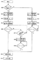
図4は着信から通話状態になるまでの動作を示すフローチャート図である。待受状態の携帯電話機に着信があれば(ステップS21)、まず始めに制御回路2は開閉検出回路1からの信号で携帯電話機本体の開閉状態を判定する(ステップS22)。
【0011】
ステップS22で本体が閉じていると判定された場合は、制御回路2からゲイン調整回路4を制御して、使用者に確実に着信を知らすことができる着信音の音量(第1の音量)となるように制御する(ステップ32)。次いで音源回路3をスタートさせ(ステップ33)、増幅回路5を介してスピーカ6より上記第1の音量で着信音の鳴動を開始する(ステップ34)。その後、オフフックを判定し(ステップS35)、オフフックならば着信音を停止させ(ステップS30)、通話状態へ移行する(ステップS31)。なお、オフフックは例えば携帯電話機の通話ボタンが押されたかどうかで判定される。また、上記第1の音量は、着信音を発生するスピーカ6が本体内側に配置される場合は、本体外側に配置される場合に比べ、より大きな音量に設定される。
【0012】
ステップS22で本体が開いていると判定された場合は、制御回路2からゲイン調整回路4を制御して、着信音の音量が上記第1の音量よりも小さい所定の音量(第2の音量)となるように制御する(ステップ23)。次いで音源回路3をスタートさせ(ステップ24)、増幅回路5を介してスピーカ6より上記第2の音量で着信音の鳴動を開始する(ステップ25)。その後、オフフックを判定し(ステップS26)、オフフックならば着信音を停止させ(ステップS30)、通話状態へ移行する(ステップS31)。
【0013】
ステップ26にてオフフックでない場合は、制御回路2にて着信音の鳴動時間を判定し(ステップS27)、一定時間を経過した場合は、制御回路2からゲイン調整回路4を制御して、鳴動中の着信音の音量を上記第2の音量から上記第1の音量となるように制御し(ステップS28)、その後、オフフックを判定し(ステップS29)、オフフックならば着信音を停止させ(ステップS30)、通話状態へ移行する(ステップS31)。また、ステップ27にて一定時間を経過していない場合は、再びステップ26へ移行する。
【0014】
上記のように、スピーカとリンガーを兼用した折り畳み式携帯電話機において、待受状態で着信があった時点における本体の開閉状態を判定し、本体が開けられた状態で着信があった場合は、本体が閉じた状態で着信があった場合に比べて着信音の音量を小さくすることで、使用者が本体を開けて何らかの動作を行っているときに突然大きな音量の着信音が鳴動することがないようにすることができる。
【0015】
実施の形態2.
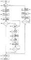
図5は実施の形態2の折り畳み式携帯電話機における着信から通話状態になるまでの動作を示すフローチャート図である。なお、ブロック図及び本体構成は、実施の形態1の図1および図2と同様である。待受状態の携帯電話機に着信があれば(ステップS41)、まず始めに制御回路2は開閉検出回路1からの信号で携帯電話機本体の開閉状態を判定する(ステップS42)。
【0016】
ステップS42で本体が閉じていると判定された場合は、上記実施の形態1と同様の動作で、制御回路2からゲイン調整回路4を制御して、使用者に確実に着信を知らすことができる着信音の音量(第1の音量)となるように制御する(ステップS54)。次いで音源回路3をスタートさせ(ステップS55)、増幅回路5を介してスピーカ6より上記第1の音量で着信音の鳴動を開始する(ステップS56)。その後、オフフックを判定し(ステップS57)、オフフックならば着信音を停止させ(ステップS52)、通話状態へ移行する(ステップS53)。
【0017】
ステップS42で本体が開いていると判定された場合は、制御回路2からゲイン調整回路4を制御して、着信音の音量が最小ゲインとなるように制御する(ステップS43)。次いで音源回路3をスタートさせ(ステップS44)、増幅回路5を介してスピーカ6より最小ゲイン音量で着信音の鳴動を開始する(ステップS45)。その後、オフフックを判定し(ステップS46)、オフフックならば最小ゲインのまま着信音を停止させ(ステップS52)、通話状態へ移行する(ステップS53)。
【0018】
ステップS46にてオフフックでない場合、制御回路2にて音量を徐々に(段階的に)大きくする単位時間の経過を判定し(ステップS47)、音量を大きくする単位時間が経過した場合は、制御回路2からゲイン調整回路4を制御して、音量を時間の経過に対応した分だけ大きくし(ステップS48)、音量を大きくする時間に達していない場合は、音量は現状のままとして次ぎのステップS49へ移行する。例えば音量を大きくする単位時間を5秒間とした場合、着信音の鳴動開始から5秒間は最小ゲインの音量で鳴動、次ぎの5秒間は最小ゲインから1段階大きくした音量で鳴動、さらに次ぎの5秒間は最小ゲインから2段階大きくした音量で鳴動させるというように、ステップS46でオフフックがなければ、5秒間経過する毎に、段階的に着信音の音量を大きくする。
【0019】
また、制御回路2は着信音の鳴動開始からのトータルの鳴動時間も判定し(ステップS49)、一定時間を経過した場合は制御回路2からゲイン調整回路4を制御して、ステップS42で本体が閉じていた場合と同じ第1の音量となるように制御する(ステップS50)。その後、オフフックを判定し(ステップS51)、オフフックならば着信音を停止させ(ステップS52)、通話状態へ移行する(ステップS53)。なお、ステップS49にて一定時間を経過していない場合は、再びステップS46へ移行するが、ステップS48にて音量を大きくする制御を実施した場合は、再びステップ46へ移行した際にオフフックであった場合は、最小ゲインでなく、大きくなった分の音量のまま着信音を停止させ(ステップS52)、通話状態へ移行する(ステップS53)。
【0020】
上記のように、スピーカとリンガーを兼用した折り畳み式携帯電話機において、待受状態で着信があった時点における本体の開閉状態を判定し、本体が開けられた状態で着信があった場合は、最小ゲインから着信音の鳴動を開始し、時間の経過と共に着信音の音量を徐々に大きくしていくことで、使用者が本体を開けて何らかの動作を行っているときに突然大きな音量の着信音が鳴動することを防止できるとともに、使用者に確実に着信を知らすことができる。
【0021】
発明の実施形態3.
図6は実施の形態3の折り畳み式携帯電話機における着信から通話状態になるまでの動作を示すフローチャート図である。なお、ブロック図及び本体構成は、実施の形態1の図1および図2と同様である。待受状態の携帯電話機に着信があれば(ステップS61)、まず始めに制御回路2は開閉検出回路1からの信号で携帯電話機本体の開閉状態を判定する(ステップS62)。
【0022】
ステップS62で本体が閉じていると判定された場合は、制御回路2からゲイン調整回路4を制御して、使用者に確実に着信を知らすことができる着信音の音量(第1の音量)となるように制御する(ステップS75)。次いで音源回路3に所定の着信音の音(第1種音)を設定してスタートさせる(ステップS76)。通常この第1種音は使用者に着信音としてよく聞こえるように音圧レベルが高いものに設定される。次いで増幅回路5を介してスピーカ6より上記第1の音量及び第1種音で着信音の鳴動を開始する(ステップS77)。その後、オフフックを判定し(ステップS78)、オフフックならば着信音を停止させ(ステップS73)、通話状態へ移行する(ステップS74)。
【0023】
ステップS62で本体が開いていると判定された場合は、制御回路2からゲイン調整回路4を制御して、着信音の音量が上記第1の音量よりも小さい所定の音量(第2の音量)となるように制御する(ステップS63)。次いで音源回路3には着信音として上記第1種音より音圧レベルが低い上記第1種音とは異なる音もしくは音声(第2種音)を設定してスタートさせ(ステップS64)、増幅回路5を介してスピーカ6より上記第2の音量及び第2種音で着信音の鳴動を開始する(ステップS65)。その後、オフフックを判定し(ステップS66)、オフフックならば着信音を停止させ(ステップS73)、通話状態へ移行する(ステップS74)。
【0024】
ステップS66にてオフフックでない場合は、制御回路2にて着信音の鳴動時間を判定し(ステップS67)、一定時間を経過した場合は、音源回路3にて設定されていた上記第2種音の設定をストップする(ステップS68)。次いで制御回路2からゲイン調整回路4を制御して、鳴動中の着信音の音量を上記第2の音量から上記第1の音量となるように制御し(ステップS69)、音源回路3には上記第1種音を設定してスタートさせる(ステップS70)。次いで増幅回路5を介してスピーカ6より上記第1の音量及び第1種音で着信音の鳴動を開始する(ステップS71)。その後、オフフックを判定し(ステップS72)、オフフックならば着信音を停止させ(ステップS73)、通話状態へ移行する(ステップS74)。また、ステップS67にて一定時間を経過していない場合は、再びステップ66へ移行する。
【0025】
上記のように、スピーカとリンガーを兼用した折り畳み式携帯電話機において、待受状態で着信があった時点における本体の開閉状態を判定し、本体が開けられた状態で着信があった場合は、本体が閉じた状態で着信があった場合に比べて着信音の音量を小さくするとともに、音質を変える(音圧レベルを低くする)ことで、使用者が本体を開けて何らかの動作を行っているときに突然大きな音量および音圧レベルの高い着信音が鳴動することがないようにすることができる。
【0026】
実施の形態4.
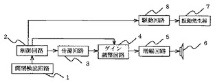
図7、図8はこの発明の実施の形態4における折り畳み式携帯電話機のブロック図およびフローチャート図である。上記実施の形態1〜実施の形態3では、着信時における本体の開閉状態の判定結果に応じて、着信音の音量または音質を制御するようにしたが、この実施の形態4では、携帯電話機本体の振動または着信音の鳴動により着信を使用者に知らせるようにしたものである。図7において、携帯電話機本体の開閉状態は開閉検出回路1で検出され、この開閉検出回路1からの信号により本体の開閉状態を判定および携帯電話機内の各動作の制御、時間情報を制御回路2で管理する。着信音等の各種音は音源回路3に保有され、この音源回路3から出力される音源の音量は、制御回路2により制御されるゲイン調整回路4で調整する。ゲイン調整回路4から出力された音の電気信号は増幅回路5を介してスピーカ6で音に変換される。また、着信を携帯電話機本体の振動で使用者に知らせる振動発生器7は駆動回路8を介して制御回路2により制御され、着信を携帯電話機本体の振動で使用者に知らせることができる。
【0027】
図8は着信から通話状態になるまでの動作を示すフローチャート図である。待受状態の携帯電話機に着信があれば(ステップS91)、まず始めに制御回路2は開閉検出回路1からの信号で携帯電話機本体の開閉状態を判定する(ステップS92)。
【0028】
ステップS92で本体が閉じていると判定された場合は、制御回路2からゲイン調整回路4を制御して、使用者に確実に着信を知らすことができる着信音の音量を設定する(ステップS104)。次いで音源回路3をスタートさせ(ステップ105)、増幅回路5を介してスピーカ6より着信音の鳴動を開始する(ステップ106)。その後、オフフックを判定し(ステップS107)、オフフックならば着信音を停止させ(ステップS102)、通話状態へ移行する(ステップS103)。
【0029】
ステップS92で本体が開いていると判定された場合は、制御回路2から駆動回路8を制御して振動発生器7の駆動を開始する(ステップS93)。その後、オフフックを判定し(ステップS94)、オフフックならば振動発生器7の駆動を停止させ(ステップS101)、通話状態へ移行する(ステップS103)。
【0030】
ステップ94にてオフフックでない場合は、制御回路2にて振動発生器7の駆動時間を判定し(ステップS95)、一定時間を経過した場合は、振動発生器7の駆動を停止させ(ステップS96)、制御回路2からゲイン調整回路4を制御して、着信音の音量を設定する(ステップS97)。次いで音源回路3をスタートさせ(ステップS98)、増幅回路5を介してスピーカ6より着信音の鳴動を開始する(ステップS99)。その後、オフフックを判定し(ステップS100)、オフフックならば着信音を停止させ(ステップS102)、通話状態へ移行する(ステップS103)。
【0031】
上記のように、折り畳み式携帯電話機において、待受状態で着信があった時点における本体の開閉状態を判定し、本体が開けられた状態で着信があった場合は、振動発生器を駆動させることで、着信を使用者に通知するようにしたので、使用者が本体を開けて何らかの動作を行っているときに突然大きな音量の着信音が鳴動することがないようにすることができる。
【0032】
【発明の効果】
以上のように、この発明によれば、折り畳み可能な本体と、この本体の開閉を検出する開閉検出手段と、着信を報知するための着信音を発生させるスピーカと、前記本体が閉じている状態で着信した時は、前記着信音を第1の音量で鳴動させ、前記本体が開いている状態で着信した時は、前記着信音を前記第1の音量よりも小さくした第2の音量で鳴動させる制御回路を備えたことにより、本体が開けられた状態で着信があった場合に、突然大きな音量の着信音が鳴動することがなく、使用者の使用状況を考慮した着信音による着信の通知を可能とした折り畳み式携帯電話機を得ることができる。
【図面の簡単な説明】
【図1】本発明の実施の形態1における折り畳み式携帯電話機のブロック図である。
【図2】本発明の実施の形態1における折り畳み式携帯電話機の本体を開いた状態を示す斜視図である。
【図3】本発明の実施の形態1における折り畳み式携帯電話機の本体を閉じた状態を示す一部断面側面図である。
【図4】本発明の実施の形態1における着信から通話状態になるまでの動作を示すフローチャート図である。
【図5】本発明の実施の形態2における着信から通話状態になるまでの動作を示すフローチャート図である。
【図6】本発明の実施の形態3における着信から通話状態になるまでの動作を示すフローチャート図である。
【図7】本発明の実施の形態4における折り畳み式携帯電話機のブロック図である。
【図8】本発明の実施の形態4における着信から通話状態になるまでの動作を示すフローチャート図である。
【符号の説明】
1 開閉検出回路
2 制御回路
3 音源回路
4 ゲイン調整回路
5 増幅回路
6 スピーカ
7 振動発生器
8 駆動回路[0001]
TECHNICAL FIELD OF THE INVENTION
The present invention relates to a foldable mobile phone that performs a call and various operations while a main body is open.
[0002]
[Prior art]
Conventional foldable mobile phones are provided with open / close detection means for detecting that the foldable main body has been opened, and when it is detected that the main body has been opened, the ringtone is stopped or the volume is reduced. Configuration. (For example, see Patent Document 1).
[0003]
[Patent Document 1]
JP-A-8-307488 (page 1)
[0004]
[Problems to be solved by the invention]
In a mobile phone, if there is an incoming call, a ring tone is generated to notify the user of the incoming call. When the mobile phone is not in use (standby), the mobile phone is usually put in the pocket or bag of the user's clothes, and the volume of the ringtone should be assured to the user, assuming the above case. It is set large enough to be able to notify you of an incoming call. Further, in a foldable mobile phone, when the ring tone generating means is disposed inside the main body with the main body closed, it is necessary to generate a ring tone at a higher volume. In any case, the volume of the ring tone that sounds when the main body is opened is too large, and there is a possibility that the user or a nearby person may be excessively uncomfortable.
[0005]
Therefore, in the conventional foldable mobile phone, when it is detected that the main body is opened after an incoming call, the ring tone is stopped or the volume is reduced, but the incoming call is received with the main body opened. Is not taken into account, and in this case a large volume ringtone will suddenly sound, despite the assumption that the user is performing some operation, There is a problem that this may cause excessive discomfort to the person.
[0006]
SUMMARY OF THE INVENTION The present invention has been made to solve the above-described problem, and a foldable mobile phone that does not suddenly emit a large volume ringtone when an incoming call is received with the main body opened. What you get.
[0007]
[Means for Solving the Problems]
In the foldable mobile phone according to the present invention, a foldable main body, open / close detection means for detecting opening / closing of the main body, a speaker for generating a ring tone for notifying an incoming call, and a state in which the main body is closed When an incoming call is received, the ring tone sounds at a first volume, and when an incoming call arrives with the main body open, the ring tone sounds at a second volume lower than the first volume. And a control circuit for performing the control.
[0008]
BEST MODE FOR CARRYING OUT THE INVENTION
A foldable mobile phone according to a first embodiment of the present invention will be described with reference to FIGS. FIG. 1 is a block diagram. In FIG. 1, the open / close state of the main body of the mobile phone is detected by an open /
[0009]
FIG. 2 shows a state where the mobile phone body is opened, and FIG. 3 shows a state where the mobile phone body is closed. In FIGS. 2 and 3, a
[0010]
FIG. 4 is a flowchart showing the operation from the incoming call to the call state. If there is an incoming call to the mobile phone in the standby state (step S21), first, the control circuit 2 determines the open / closed state of the mobile phone body based on the signal from the open / close detection circuit 1 (step S22).
[0011]
If it is determined in step S22 that the main body is closed, the control circuit 2 controls the
[0012]
If it is determined in step S22 that the main body is open, the control circuit 2 controls the
[0013]
If it is not off-hook in
[0014]
As described above, in the foldable mobile phone that also functions as the speaker and the ringer, the open / close state of the main body when the incoming call is received in the standby state is determined. By lowering the volume of the ring tone compared to when there is an incoming call with the phone closed, the ring tone does not suddenly sound loud when the user opens the main unit and performs any operation. You can do so.
[0015]
Embodiment 2 FIG.
FIG. 5 is a flowchart showing the operation of the foldable mobile phone according to the second embodiment from the incoming call to the call state. Note that the block diagram and the main body configuration are the same as those in FIGS. 1 and 2 of the first embodiment. If there is an incoming call to the mobile phone in the standby state (step S41), first, the control circuit 2 determines the open / close state of the main body of the mobile phone based on a signal from the open / close detection circuit 1 (step S42).
[0016]
If it is determined in step S42 that the main body is closed, the control circuit 2 controls the
[0017]
If it is determined in step S42 that the main body is open, the control circuit 2 controls the
[0018]
If it is not off-hook in step S46, the control circuit 2 determines the elapse of a unit time for increasing the volume gradually (stepwise) (step S47), and if the unit time for increasing the volume has elapsed, the control circuit 2 2 to control the
[0019]
Further, the control circuit 2 also determines the total ringing time from the start of ringing of the ringtone (step S49), and when a certain time has elapsed, the control circuit 2 controls the
[0020]
As described above, in a foldable mobile phone that also functions as a speaker and a ringer, the open / close state of the main body when a call is received in a standby state is determined. By starting the ring tone from the gain and gradually increasing the volume of the ring tone over time, the ring tone suddenly becomes loud when the user opens the main unit and performs some operation. Ringing can be prevented, and the user can be reliably notified of the incoming call.
[0021]
FIG. 6 is a flowchart showing an operation of the foldable mobile phone according to the third embodiment from an incoming call to a call. Note that the block diagram and the main body configuration are the same as those in FIGS. 1 and 2 of the first embodiment. If there is an incoming call to the mobile phone in the standby state (step S61), first, the control circuit 2 determines the open / closed state of the mobile phone body based on a signal from the open / close detection circuit 1 (step S62).
[0022]
If it is determined in step S62 that the main body is closed, the control circuit 2 controls the
[0023]
If it is determined in step S62 that the main body is open, the control circuit 2 controls the
[0024]
If it is not off-hook in step S66, the ringing time of the ring tone is determined by the control circuit 2 (step S67). If a predetermined time has elapsed, the second seed tone set in the
[0025]
As described above, in the foldable mobile phone that also functions as the speaker and the ringer, the open / close state of the main body when the incoming call is received in the standby state is determined. When the user opens the main unit and performs some operation by lowering the volume of the ringtone and changing the sound quality (lowering the sound pressure level) compared to when there is an incoming call with the closed It is possible to prevent sudden ringing of a large volume and a high sound pressure level.
[0026]
7 and 8 are a block diagram and a flowchart of a foldable mobile phone according to
[0027]
FIG. 8 is a flowchart showing the operation from the incoming call to the call state. If there is an incoming call to the mobile phone in the standby state (step S91), first, the control circuit 2 determines the open / closed state of the mobile phone body based on the signal from the open / close detection circuit 1 (step S92).
[0028]
If it is determined in step S92 that the main body is closed, the control circuit 2 controls the
[0029]
If it is determined in step S92 that the main body is open, the control circuit 2 controls the
[0030]
If it is not off-hook in step 94, the drive time of the
[0031]
As described above, in the foldable mobile phone, the open / close state of the main body at the time of an incoming call in the standby state is determined, and when there is an incoming call with the main body opened, the vibration generator is driven. Thus, since the user is notified of the incoming call, it is possible to prevent the ring tone of a large volume from suddenly sounding when the user opens the main body and performs some operation.
[0032]
【The invention's effect】
As described above, according to the present invention, a foldable main body, open / close detection means for detecting the opening / closing of the main body, a speaker for generating a ring tone for notifying an incoming call, and a state where the main body is closed When an incoming call is received, the ring tone sounds at a first volume, and when an incoming call arrives with the main body open, the ring tone sounds at a second volume lower than the first volume. When a call is received while the main body is open, a large volume ring tone does not suddenly ring, and a notification of the incoming call with a ring tone considering the usage situation of the user Can be obtained.
[Brief description of the drawings]
FIG. 1 is a block diagram of a foldable mobile phone according to
FIG. 2 is a perspective view showing a state where the main body of the foldable mobile phone according to
FIG. 3 is a partial cross-sectional side view showing a state where a main body of the foldable mobile phone according to
FIG. 4 is a flowchart showing an operation from the incoming call to the call state in the first embodiment of the present invention.
FIG. 5 is a flowchart showing an operation from the incoming call to the call state in the second embodiment of the present invention.
FIG. 6 is a flowchart showing an operation from a call reception to a call state in
FIG. 7 is a block diagram of a foldable mobile phone according to a fourth embodiment of the present invention.
FIG. 8 is a flowchart showing an operation from an incoming call to a call state according to the fourth embodiment of the present invention.
[Explanation of symbols]
REFERENCE SIGNS
Claims (5)
この本体の開閉を検出する開閉検出手段と、
着信を報知するための着信音を発生させるスピーカと、
前記本体が閉じている状態で着信した時は、前記着信音を第1の音量で鳴動させ、前記本体が開いている状態で着信した時は、前記着信音を前記第1の音量よりも小さくした第2の音量で鳴動させる制御回路とを備えたことを特徴とする折り畳み式携帯電話機。A foldable body,
Opening and closing detecting means for detecting opening and closing of the main body,
A speaker for generating a ring tone for notifying an incoming call;
When an incoming call is received with the main body closed, the ring tone sounds at a first volume, and when an incoming call is received with the main body open, the ring tone is lower than the first volume. And a control circuit for generating a sound at a second volume.
この本体の開閉を検出する開閉検出手段と、
着信を報知するための着信音を発生させるスピーカと、
前記本体が閉じている状態で着信した時は、第1の着信音を鳴動させ、前記本体が開いている状態で着信した時は、前記着信音を前記第1の着信音と異なる音もしくは音声による第2の着信音を鳴動させる制御回路とを備えたことを特徴とする折り畳み式携帯電話機。A foldable body,
Opening and closing detecting means for detecting opening and closing of the main body,
A speaker for generating a ring tone for notifying an incoming call;
When an incoming call is received with the main body closed, a first ring tone is sounded, and when the incoming call is received with the main body open, the ring tone is different from the first ring tone or voice. And a control circuit for sounding a second ringtone according to claim 1.
この本体の開閉を検出する開閉検出手段と、
着信を報知するための着信音を発生させるスピーカと、
着信時に着信を報知するための振動を発生する振動発生器と、
前記本体が閉じている状態で着信した時は、着信音を鳴動させ、前記本体が開いている状態で着信した時は、前記振動発生器を動作させる制御回路とを備えたことを特徴とする折り畳み式携帯電話機。A foldable body,
Opening and closing detecting means for detecting opening and closing of the main body,
A speaker for generating a ring tone for notifying an incoming call;
A vibration generator that generates vibrations to notify the user of an incoming call;
And a control circuit for operating the vibration generator when an incoming call is received while the main body is closed, when a call is received while the main body is closed. Foldable mobile phone.
Priority Applications (1)
| Application Number | Priority Date | Filing Date | Title |
|---|---|---|---|
| JP2002337798A JP2004173049A (en) | 2002-11-21 | 2002-11-21 | Folding mobile phone |
Applications Claiming Priority (1)
| Application Number | Priority Date | Filing Date | Title |
|---|---|---|---|
| JP2002337798A JP2004173049A (en) | 2002-11-21 | 2002-11-21 | Folding mobile phone |
Publications (2)
| Publication Number | Publication Date |
|---|---|
| JP2004173049A true JP2004173049A (en) | 2004-06-17 |
| JP2004173049A5 JP2004173049A5 (en) | 2005-09-29 |
Family
ID=32701204
Family Applications (1)
| Application Number | Title | Priority Date | Filing Date |
|---|---|---|---|
| JP2002337798A Pending JP2004173049A (en) | 2002-11-21 | 2002-11-21 | Folding mobile phone |
Country Status (1)
| Country | Link |
|---|---|
| JP (1) | JP2004173049A (en) |
Cited By (6)
| Publication number | Priority date | Publication date | Assignee | Title |
|---|---|---|---|---|
| JP2006284904A (en) * | 2005-03-31 | 2006-10-19 | Omron Entertainment Kk | Terminal device, totalizing system, method and program for controlling terminal device, and computer-readable recording medium |
| JP2007006377A (en) * | 2005-06-27 | 2007-01-11 | Toshiba Corp | Mobile radio terminal equipment |
| WO2008065844A1 (en) * | 2006-11-27 | 2008-06-05 | Nec Corporation | Mobile terminal, mobile terminal receipt notifying method and program |
| US7634299B2 (en) | 2004-09-02 | 2009-12-15 | Pioneer Corporation | Communication terminal apparatus, method of changing function and/or setting of communication terminal apparatus, and program |
| JP2009296294A (en) * | 2008-06-05 | 2009-12-17 | Toshiba Corp | Communication terminal apparatus |
| JP2011205715A (en) * | 2011-07-19 | 2011-10-13 | Fujitsu Toshiba Mobile Communications Ltd | Mobile radio terminal device |
-
2002
- 2002-11-21 JP JP2002337798A patent/JP2004173049A/en active Pending
Cited By (8)
| Publication number | Priority date | Publication date | Assignee | Title |
|---|---|---|---|---|
| US7634299B2 (en) | 2004-09-02 | 2009-12-15 | Pioneer Corporation | Communication terminal apparatus, method of changing function and/or setting of communication terminal apparatus, and program |
| JP2006284904A (en) * | 2005-03-31 | 2006-10-19 | Omron Entertainment Kk | Terminal device, totalizing system, method and program for controlling terminal device, and computer-readable recording medium |
| JP2007006377A (en) * | 2005-06-27 | 2007-01-11 | Toshiba Corp | Mobile radio terminal equipment |
| WO2008065844A1 (en) * | 2006-11-27 | 2008-06-05 | Nec Corporation | Mobile terminal, mobile terminal receipt notifying method and program |
| US8670367B2 (en) | 2006-11-27 | 2014-03-11 | Nec Corporation | Mobile terminal, method and program of notifying incoming call for mobile terminal |
| JP5663138B2 (en) * | 2006-11-27 | 2015-02-04 | レノボ・イノベーションズ・リミテッド(香港) | Mobile terminal, incoming notification method and program for mobile terminal |
| JP2009296294A (en) * | 2008-06-05 | 2009-12-17 | Toshiba Corp | Communication terminal apparatus |
| JP2011205715A (en) * | 2011-07-19 | 2011-10-13 | Fujitsu Toshiba Mobile Communications Ltd | Mobile radio terminal device |
Similar Documents
| Publication | Publication Date | Title |
|---|---|---|
| CN1166157C (en) | Telephone set | |
| JP5578313B2 (en) | Audio output device | |
| JP3138666B2 (en) | Mobile phone | |
| JP2004173049A (en) | Folding mobile phone | |
| JP2000244618A (en) | Foldable portable telephone set | |
| JP2001268187A (en) | Call tone ringing system and method for flip type mobile phone | |
| JP2005236385A (en) | Mobile communication terminal | |
| JP2010063158A (en) | Portable telephone set and control method thereof | |
| JP4972886B2 (en) | Mobile radio terminal device | |
| JP4534753B2 (en) | Portable terminal, its state notification method, and computer program for portable terminal | |
| JP3957609B2 (en) | Mobile phone, control method thereof, and computer program | |
| JP4073096B2 (en) | Ring tone control apparatus and ring tone control method for mobile communication terminal | |
| JP2004015681A (en) | Communication device and incoming call notifying method thereof | |
| JP2004242050A (en) | Radio terminal and method for adjusting sound volume of received call thereof | |
| KR20010008937A (en) | Calling tone output level automatical control and calling mode automatical control method | |
| JP2004056651A (en) | Portable information terminal | |
| JPH0888674A (en) | Call signal generating circuit | |
| JP4672519B2 (en) | Communication terminal and mobile phone | |
| JPH114281A (en) | Telephone set | |
| JP2005341329A (en) | Portable telephone terminal and portable telephone system | |
| KR100400560B1 (en) | Method for notifying incoming call in portable terminal | |
| JP2004080616A (en) | System and method for controlling ringer sound volume by detecting vibration of portable telephone | |
| JP2000232500A (en) | Telephone device | |
| JP2000216862A (en) | Portable telephone set | |
| JP4918884B2 (en) | Mobile device |
Legal Events
| Date | Code | Title | Description |
|---|---|---|---|
| RD01 | Notification of change of attorney |
Free format text: JAPANESE INTERMEDIATE CODE: A7421 Effective date: 20040712 |
|
| A521 | Request for written amendment filed |
Free format text: JAPANESE INTERMEDIATE CODE: A523 Effective date: 20050421 |
|
| A621 | Written request for application examination |
Free format text: JAPANESE INTERMEDIATE CODE: A621 Effective date: 20050421 |
|
| A131 | Notification of reasons for refusal |
Free format text: JAPANESE INTERMEDIATE CODE: A131 Effective date: 20061121 |
|
| A02 | Decision of refusal |
Free format text: JAPANESE INTERMEDIATE CODE: A02 Effective date: 20070320 |