JP2004172845A - Imaging device - Google Patents
Imaging device Download PDFInfo
- Publication number
- JP2004172845A JP2004172845A JP2002335096A JP2002335096A JP2004172845A JP 2004172845 A JP2004172845 A JP 2004172845A JP 2002335096 A JP2002335096 A JP 2002335096A JP 2002335096 A JP2002335096 A JP 2002335096A JP 2004172845 A JP2004172845 A JP 2004172845A
- Authority
- JP
- Japan
- Prior art keywords
- pixels
- image
- image sensor
- electronic zoom
- signal
- Prior art date
- Legal status (The legal status is an assumption and is not a legal conclusion. Google has not performed a legal analysis and makes no representation as to the accuracy of the status listed.)
- Withdrawn
Links
Images


Abstract
Description
【0001】
【発明の属する技術分野】
本発明は、多画素の撮像素子を使用した撮像装置で、静止画撮影と動画撮影の両方に供せる物の動作に関するものである。
【0002】
【従来の技術】
半導体の微細化によって、撮像素子も微細化微細画素化されている。そのために動画像撮影用の撮像装置でも、動画記録画素以上の画素数の撮像素子を使用し、その多画素を利用して動画の撮影とともに静止画の撮影にも共用して使用できる装置が増加している。
【0003】
図4で説明するが、この例及び以下の実施例も含む各例では図5の様に撮像素子に水平2160画素、垂直1440ラインの物を使用するものとして説明する。
【0004】
図4において400は撮像するためのレンズ、401はレンズ400を通過する光の量を制御する絞り装置、402は結像された光学像を電気信号に変換するCCD撮像素子、403は増幅率を適時変更可能なゲインコントロールアンプ、404はアナログ信号をデジタル信号に変換するA/Dコンバータ、405は撮像信号を記録するためのデータに変換するための信号処理回路、407は各部に動作タイミング信号を供給するためのタイミングジェネレータ、408は前記夫々を制御するためのコントローラ、409は入力された画像信号の画像サイズを変換するための縮小処理回路である。
【0005】
レンズ400、絞り401を通過した光学像はCCD撮像素子402で電気信号に変換される。CCD撮像素子402から得られた撮像信号は、ゲインコントロールアンプ403でアナログ的に前処理され、A/Dコンバータ404によってサンプリング、信号処理回路405によって記録画像信号に処理され、その後動画撮影時には記録フォーマットに則った画素数になるように縮小処理回路409を経て記録媒体に記録され、一方静止画記録時にはそのままの画素数で記録媒体に送られる。各部の制御はコントローラ408からの制御信号でなされ、それに基づきタイミングジェネレータ407が各部に適切なタイミング信号を供給するものである。
【0006】
この時、動画像を記録するためにはフレームレート(NTSCでは約1/60秒)で必要な画素からの信号を読み出さねばならず、そうした場合に多画素の撮像素子全てより信号を読み出すように駆動してやると、非常に高速の読み出し動作クロックになってしまい、撮像素子の電荷の転送効率の低下を引き起こす等の不具合を生じさせる。
【0007】
本例の水平2160画素、垂直1440ラインの撮像素子を60フレームで読み出した場合、2160×1440×60=187MHzと言う読み出し速度になってしまい、撮像素子の電荷の転送の効率が著しく低下してしまう。なお、静止画撮影時にはフレームレートに拘束されないので、読み出し速度を十分な速度まで落とすことが出来る。
【0008】
ただし、記録される画素数は元々多画素の素子全ての画素よりは少ないので、通常の多画素素子利用の撮像装置では多画素の撮像素子のなかから、動画像に必要なだけの画素信号だけを切り出し、選択的に読み出すように駆動することで、通常の画素数の撮像素子を駆動するのと同じ速度で動作、読み出しが可能にする事が多い。
【0009】
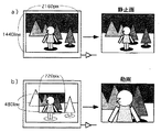
これは図6の様に、静止画撮影時は図6a)の様に全画素を読み出すように撮像素子を駆動する。この時フレームレートには拘束されないので十分読み出し可能な速度での駆動を行う。一方動画撮影時には図6b)の様に撮像素子の中心部分から記録フォーマットに必要なだけのラインの読み出しを行うことで、転送効率の低下しない程度での読み出しが十分可能になるものである。
【0010】
しかしこの方式では、図6からも判るように、同一焦点距離のレンズを通して撮影された画像の画角が静止画と動画で大きく異なるものとなってしまう。
【0011】
そこで、動画撮影時においては垂直に複数の画素を加算して読み出すことにより、前記の問題点を解決する方法が知られている。
【0012】
これを図7で説明するが、垂直1440ラインの撮像素子の場合、垂直転送CCDの3ライン分を垂直転送CCD上で加算し、垂直に3ラインの加算信号として読み出すことで、垂直の読み出しライン数は相対的に480ラインとなり、垂直の転送速度は1/3で済むようになるために、フルフレームでの読み出しを行ったとしても転送効率は低下することなく、電荷の転送が可能となるものである。
【0013】
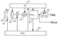
この時の回路構成は図8のようになる。各番号の機能は図4と同じである。
【0014】
さらにこの方式を利用し、図9の回路の様に信号処理回路905から得られた信号の拡大縮小を行う電子ズーム回路906を付加することで、図10の様に3ラインの加算を行い全画面分から読み出す方式と、2ラインの加算を行いさらに記録ライン数の倍のライン分(480×2=960ライン)から切り出して読み出しを行う方式と、ライン加算を行わず記録ライン数の分だけ(480ライン)を切り出して読み出す方式とを切り替えて、これに前記電子ズーム回路906を組み合わせることで、画像の劣化の少ない高倍率の電子ズームを可能とするシステムが考案されている。
【0015】
この時の電子ズーム回路の設定をするコントローラの動作は図11のようになる。通常撮影時では電子ズーム倍率の設定は1倍であり、その時の垂直ラインの加算は3ライン加算、電子ズーム回路906の倍率は1倍となる。そして電子ズームを動作させていく場合、電子ズーム倍率設定が1倍から1.5倍までの間は3ライン加算の信号を用い後段の電子ズーム回路906の倍率に順次電子ズーム倍率設定を代入して拡大していく。
【0016】
さらに拡大を続け電子ズーム倍率設定が1.5倍に達した時点で、今度は垂直ラインの加算を2ライン加算とし、電子ズーム回路906の倍率設定を電子ズーム倍率設定を1.5で除算したものを代入していく様にする。
【0017】
さらに拡大を続け、電子ズーム倍率設定が3倍に達した時点で、今度は垂直ラインの加算止め1ライン読み出しとし、電子ズーム回路906の倍率設定を電子ズーム倍率設定を3で除算したものを代入していく様にする。
【0018】
【発明が解決しようとする課題】
しかしながら、前記電子ズーム動作では、3ラインの加算を行う場合と、2ラインの加算を行う場合と、加算を行わず1ライン分だけの場合とでは、当然ながら「3画素分の電荷相当」「2画素分の電荷相当」「1画素分の電荷相当」と、それぞれ撮像素子から出てくる1画素当たりの信号電荷量に大きな差が出てしまうこととなる。
【0019】
その為に、電子ズームを行っていく途中、加算ライン数の切り替えの時点に於て、画面の明るさの変化が生じ、不自然な画面となってしまう。また、これを防ぐために露出制御用の絞り900を変化させたとしても、絞りの追従速度はあまり高速には出来ないためにどうしても或る期間は画面の明るさが不連続なものとなる。
【0020】
【課題を解決するための手段】
本発明では、上記問題点に鑑み、加算ライン数の切り替えタイミングに応じて、電子シャッターを制御することで、読み出される画素当たりの電荷量を一定に保ち様にするものである。
【0021】
【発明の実施の形態】
本発明の実施例を図1で示す。
【0022】
図1において100は撮像するためのレンズ、101はレンズ400を通過する光の量を制御する絞り装置、102は結像された光学像を電気信号に変換するCCD撮像素子、103は増幅率を適時変更可能なゲインコントロールアンプ、104はアナログ信号をデジタル信号に変換するA/Dコンバータ、105は撮像信号を記録するためのデータに変換するための信号処理回路、106は信号処理回路105から得られた信号の拡大縮小を行う電子ズーム回路、107は各部に動作タイミング信号を供給するためのタイミングジェネレータ、108は前記夫々を制御するためのコントローラである。
【0023】
レンズ100、絞り101を通過した光学像はCCD撮像素子102で電気信号に変換される。CCD撮像素子102から得られた撮像信号は、ゲインコントロールアンプ103でアナログ的に前処理され、A/Dコンバータ104によってサンプリング、信号処理回路105によって記録画像信号に処理され、その後動画撮影時には電子ズーム回路106にて適時拡大縮小処理を施された後記録媒体に記録され、一方静止画記録時にはそのままの画素数で記録媒体に送られる。各部の制御はコントローラ108からの制御信号でなされ、それに基づきタイミングジェネレータ107が各部に適切なタイミング信号を供給するものである。
【0024】
本発明の実施例におけるコントローラ108の動作を示したのが図2である。通常撮影時では電子ズーム倍率の設定は1倍であり、その時のCCD撮像素子102の垂直ラインの加算は3ライン加算、電子シャッター速度は1/180となり、電子ズーム回路106の倍率は1倍となる。
【0025】
そして電子ズームを動作させていく場合、電子ズーム倍率設定が1倍から1.5倍までの間は同様に3ライン加算の信号を用い後段の電子ズーム回路106の倍率に順次電子ズーム倍率設定を代入して拡大していく。
【0026】
さらに拡大を続け電子ズーム倍率設定が1.5倍に達した時点で、今度はCCD撮像素子102の垂直ラインの加算を2ライン加算、電子シャッター速度は1/120とし、電子ズーム回路の倍率設定を電子ズーム倍率設定を1.5で除算したものを代入していく様にする。
【0027】
さらに拡大を続け、電子ズーム倍率設定が3倍に達した時点で、今度はCCD撮像素子102の垂直ラインの加算を止め非加算読み出し、電子シャッター速度は1/60とし、電子ズーム回路の倍率設定を電子ズーム倍率設定を3で除算したものを代入していく様にする。
【0028】
[他の実施例]
本発明の第二の実施例を示す。本発明は前述第一の実施例及び従来の例の図1と構成は同じであるが、電子ズーム回路106の設定をするコントローラ108の動作は図3のようになる。
【0029】
通常撮影時では電子ズーム倍率の設定は1倍であり、その時のCCD撮像素子102の垂直ラインの加算は3ライン加算、電子シャッター速度は1/90、ゲインコントロールアンプ103の増幅率は1倍、電子ズーム回路106の倍率は1倍となる。
【0030】
そして電子ズームを動作させていく場合、電子ズーム倍率設定が1倍から1.5倍までの間は同様に3ライン加算の信号を用い後段の電子ズーム回路106の倍率に順次電子ズーム倍率設定を代入して拡大していく。
【0031】
さらに拡大を続け電子ズーム倍率設定が1.5倍に達した時点で、今度はCCD撮像素子102の垂直ラインの加算を2ライン加算、電子シャッター速度は1/60、ゲインコントロールアンプ103の増幅率は1倍とし、電子ズーム回路106の倍率設定を電子ズーム倍率設定を1.5で除算したものを代入していく様にする。
【0032】
さらに拡大を続け、電子ズーム倍率設定が3倍に達した時点で、今度はCCD撮像素子102の垂直ラインの加算を止め非加算読み出し、電子シャッター速度は1/60、ゲインコントロールアンプ103の増幅率は2倍とし、電子ズーム回路106の倍率設定を電子ズーム倍率設定を3で除算したものを代入していく様にする。
【0033】
【発明の効果】
本発明によれば、垂直ライン画素加算を行い全画面の画素からの信号を読み出して動画像を記録する装置に於て、垂直ライン画素加算の加算数の切り替えと電子ズームの併用で高画質の電子ズームを得るような構成の時に、加算数の切り替えの時点での読み出し電荷量が一定になり、得られる画面の明るさに不連続を生じなくすることが出来るようになるものである。
【図面の簡単な説明】
【図1】本発明の実施例の構成である。
【図2】本発明図1の第一の実施例のコントローラの動作を示したものである。
【図3】本発明図1の第二の実施例のコントローラの動作を示したものである。
【図4】従来の例の構成図である。
【図5】本発明及び従来の発明の各例で使われる撮像素子の例である。
【図6】従来の例図4での撮像の様子を示したものである。
【図7】従来の例での撮像素子における画素加算の例を示したものである。
【図8】従来の例の構成図である。
【図9】従来の例の構成図である。
【図10】従来の例の電子ズームの動作を示したものである。
【図11】従来の例図9のコントローラの動作を示したものである。
【符号の説明】
100 レンズ
101 絞り装置
102 CCD撮像素子
103 ゲインコントロールアンプ
104 A/Dコンバータ
105 信号処理回路
106 電子ズーム回路
107 タイミングジェネレータ
108 コントローラ
400 レンズ
401 絞り装置
402 CCD撮像素子
403 ゲインコントロールアンプ
404 A/Dコンバータ
405 信号処理回路
407 タイミングジェネレータ
408 コントローラ
409 縮小処理回路
800 レンズ
801 絞り装置
802 CCD撮像素子
803 ゲインコントロールアンプ
804 A/Dコンバータ
805 信号処理回路
807 タイミングジェネレータ
808 コントローラ
900 レンズ
901 絞り装置
902 CCD撮像素子
903 ゲインコントロールアンプ
904 A/Dコンバータ
905 信号処理回路
906 電子ズーム回路
907 タイミングジェネレータ
908 コントローラ[0001]
TECHNICAL FIELD OF THE INVENTION
The present invention relates to an operation of an image pickup apparatus using a multi-pixel image pickup device, which is used for both still image shooting and moving image shooting.
[0002]
[Prior art]
With the miniaturization of semiconductors, image sensors have been miniaturized to fine pixels. For this reason, the number of imaging devices for capturing moving images that use an image sensor with a number of pixels equal to or greater than the number of pixels for recording moving images and that can be used for both still image shooting as well as video shooting using the multiple pixels is increasing. are doing.
[0003]
As will be described with reference to FIG. 4, in each of the examples including this example and the following embodiments, it is assumed that an image sensor having 2160 pixels horizontally and 1440 lines vertically is used as shown in FIG.
[0004]
In FIG. 4,
[0005]
The optical image that has passed through the
[0006]
At this time, in order to record a moving image, signals from necessary pixels must be read at a frame rate (about 1/60 second in NTSC). In such a case, signals are read from all of the multi-pixel image sensors. If driven, a very high-speed read operation clock is generated, which causes problems such as a reduction in the charge transfer efficiency of the image sensor.
[0007]
When the image sensor having 2160 pixels in the horizontal direction and 1440 lines in the vertical direction in the present example is read out in 60 frames, the readout speed becomes 2160 × 1440 × 60 = 187 MHz, and the transfer efficiency of the charge of the image sensor is significantly reduced. I will. Since the frame rate is not restricted when capturing a still image, the reading speed can be reduced to a sufficient speed.
[0008]
However, since the number of pixels to be recorded is originally smaller than all the pixels of a multi-pixel element, in an ordinary imaging device using a multi-pixel element, only pixel signals necessary for a moving image are selected from among the multi-pixel imaging elements. In many cases, the operation and readout can be performed at the same speed as that for driving an image pickup device having a normal number of pixels by cutting out and selectively reading out.
[0009]
In this case, as shown in FIG. 6, at the time of photographing a still image, the image sensor is driven so as to read out all pixels as shown in FIG. 6A). At this time, the driving is performed at a sufficiently readable speed since the frame rate is not restricted. On the other hand, at the time of capturing a moving image, by reading out only the lines necessary for the recording format from the central portion of the image sensor as shown in FIG. 6B), the reading can be sufficiently performed without reducing the transfer efficiency.
[0010]
However, in this method, as can be seen from FIG. 6, the angle of view of an image shot through a lens having the same focal length differs greatly between a still image and a moving image.
[0011]
Therefore, there is known a method for solving the above-mentioned problem by adding a plurality of pixels vertically and reading the same when capturing a moving image.
[0012]
This will be described with reference to FIG. 7. In the case of an image pickup device having 1440 vertical lines, three lines of the vertical transfer CCD are added on the vertical transfer CCD, and are read vertically as an addition signal of three lines. Since the number is relatively 480 lines and the vertical transfer speed is only required to be 1/3, the transfer of charges can be performed without lowering the transfer efficiency even when reading in full frame. Things.
[0013]
The circuit configuration at this time is as shown in FIG. The function of each number is the same as in FIG.
[0014]
Further, by using this method and adding an
[0015]
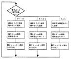
The operation of the controller for setting the electronic zoom circuit at this time is as shown in FIG. At the time of normal photographing, the setting of the electronic zoom magnification is 1, the addition of vertical lines at that time is 3 lines, and the magnification of the
[0016]
Further enlargement was continued, and when the electronic zoom magnification setting reached 1.5 times, the addition of vertical lines was set to two-line addition, and the electronic zoom magnification setting of the
[0017]
Further enlargement is continued, and when the electronic zoom magnification setting reaches three times, the addition of vertical lines is stopped and one line is read, and the value obtained by dividing the electronic zoom magnification setting by 3 into the magnification setting of the
[0018]
[Problems to be solved by the invention]
However, in the electronic zoom operation, the case of adding three lines, the case of adding two lines, and the case of performing only one line without adding, naturally, “corresponding to the charge of three pixels” “ There is a large difference between the signal charge amount for two pixels and the signal charge amount for one pixel, which is equivalent to the charge for one pixel.
[0019]
Therefore, during the electronic zoom, the brightness of the screen changes at the time of switching the number of added lines, resulting in an unnatural screen. Even if the
[0020]
[Means for Solving the Problems]
In the present invention, in view of the above problem, an electronic shutter is controlled in accordance with the switching timing of the number of addition lines, so that the amount of charge per pixel read out is kept constant.
[0021]
BEST MODE FOR CARRYING OUT THE INVENTION
An embodiment of the present invention is shown in FIG.
[0022]
In FIG. 1,
[0023]
The optical image that has passed through the
[0024]
FIG. 2 shows the operation of the
[0025]
When the electronic zoom is operated, the electronic zoom magnification is sequentially set to the magnification of the subsequent
[0026]
Further enlargement is continued, and when the electronic zoom magnification setting reaches 1.5 times, two vertical lines of the
[0027]
Further enlargement is continued, and when the electronic zoom magnification setting reaches three times, the addition of vertical lines of the
[0028]
[Other Examples]
7 shows a second embodiment of the present invention. The present invention has the same configuration as FIG. 1 of the first embodiment and the conventional example, but the operation of the
[0029]
At the time of normal photographing, the setting of the electronic zoom magnification is 1, the addition of vertical lines of the
[0030]
When the electronic zoom is operated, the electronic zoom magnification is sequentially set to the magnification of the subsequent
[0031]
Further enlargement is continued, and when the electronic zoom magnification setting reaches 1.5 times, two vertical lines of the
[0032]
When the electronic zoom magnification setting reaches three times, addition of vertical lines of the
[0033]
【The invention's effect】
According to the present invention, in a device that performs vertical line pixel addition, reads a signal from a pixel of the entire screen, and records a moving image, switching of the number of vertical line pixel additions and electronic zoom together provide high image quality. In a configuration in which the electronic zoom is obtained, the amount of charge read out at the time of switching the number of additions becomes constant, so that discontinuity does not occur in the brightness of the obtained screen.
[Brief description of the drawings]
FIG. 1 is a configuration of an embodiment of the present invention.
FIG. 2 shows the operation of the controller according to the first embodiment of the present invention shown in FIG. 1;
FIG. 3 shows the operation of the controller according to the second embodiment of FIG. 1 of the present invention.
FIG. 4 is a configuration diagram of a conventional example.
FIG. 5 is an example of an image sensor used in each example of the present invention and the conventional invention.
FIG. 6 shows an example of imaging in FIG. 4 of a conventional example.
FIG. 7 shows an example of pixel addition in an image sensor in a conventional example.
FIG. 8 is a configuration diagram of a conventional example.
FIG. 9 is a configuration diagram of a conventional example.
FIG. 10 shows the operation of a conventional example of electronic zoom.
11 shows the operation of the controller of FIG. 9 in a conventional example.
[Explanation of symbols]
Claims (2)
Priority Applications (2)
| Application Number | Priority Date | Filing Date | Title |
|---|---|---|---|
| JP2002335096A JP2004172845A (en) | 2002-11-19 | 2002-11-19 | Imaging device |
| US10/633,166 US7773129B2 (en) | 2002-08-02 | 2003-08-01 | Image pickup device, imaging apparatus containing the same, and control method thereof |
Applications Claiming Priority (1)
| Application Number | Priority Date | Filing Date | Title |
|---|---|---|---|
| JP2002335096A JP2004172845A (en) | 2002-11-19 | 2002-11-19 | Imaging device |
Publications (2)
| Publication Number | Publication Date |
|---|---|
| JP2004172845A true JP2004172845A (en) | 2004-06-17 |
| JP2004172845A5 JP2004172845A5 (en) | 2005-07-21 |
Family
ID=32699317
Family Applications (1)
| Application Number | Title | Priority Date | Filing Date |
|---|---|---|---|
| JP2002335096A Withdrawn JP2004172845A (en) | 2002-08-02 | 2002-11-19 | Imaging device |
Country Status (1)
| Country | Link |
|---|---|
| JP (1) | JP2004172845A (en) |
Cited By (10)
| Publication number | Priority date | Publication date | Assignee | Title |
|---|---|---|---|---|
| JP2007060131A (en) * | 2005-08-23 | 2007-03-08 | Olympus Imaging Corp | Camera with live view display function |
| JP2007067708A (en) * | 2005-08-30 | 2007-03-15 | Kyocera Corp | Imaging apparatus and method of forming image by it |
| JP2007142908A (en) * | 2005-11-21 | 2007-06-07 | Casio Comput Co Ltd | Imaging device and method |
| JP2007228433A (en) * | 2006-02-24 | 2007-09-06 | Canon Inc | Imaging apparatus and control method of imaging apparatus |
| JP2007295129A (en) * | 2006-04-21 | 2007-11-08 | Casio Comput Co Ltd | Imaging apparatus and electronic zoom method, and program |
| JP2008017090A (en) * | 2006-07-05 | 2008-01-24 | Casio Comput Co Ltd | Imaging apparatus and electronic zoom method |
| JP2009218725A (en) * | 2008-03-07 | 2009-09-24 | Fujifilm Corp | Imaging apparatus |
| US8363120B2 (en) | 2009-11-30 | 2013-01-29 | Sanyo Electric Co., Ltd. | Image pick-up apparatus and image pick-up method for switching a zoom range |
| WO2013039061A1 (en) * | 2011-09-13 | 2013-03-21 | Necカシオモバイルコミュニケーションズ株式会社 | Imaging device, imaging method and recording medium |
| EP2579579A1 (en) | 2011-09-26 | 2013-04-10 | Fujifilm Corporation | Imaging apparatus, imaging program and imaging method |
-
2002
- 2002-11-19 JP JP2002335096A patent/JP2004172845A/en not_active Withdrawn
Cited By (15)
| Publication number | Priority date | Publication date | Assignee | Title |
|---|---|---|---|---|
| JP2007060131A (en) * | 2005-08-23 | 2007-03-08 | Olympus Imaging Corp | Camera with live view display function |
| JP2007067708A (en) * | 2005-08-30 | 2007-03-15 | Kyocera Corp | Imaging apparatus and method of forming image by it |
| JP2007142908A (en) * | 2005-11-21 | 2007-06-07 | Casio Comput Co Ltd | Imaging device and method |
| JP2007228433A (en) * | 2006-02-24 | 2007-09-06 | Canon Inc | Imaging apparatus and control method of imaging apparatus |
| JP4655991B2 (en) * | 2006-04-21 | 2011-03-23 | カシオ計算機株式会社 | Imaging apparatus, electronic zoom method, and program |
| JP2007295129A (en) * | 2006-04-21 | 2007-11-08 | Casio Comput Co Ltd | Imaging apparatus and electronic zoom method, and program |
| US7733389B2 (en) | 2006-04-21 | 2010-06-08 | Casio Computer Co., Ltd. | Image capturing apparatus having electronic zoom function |
| JP2008017090A (en) * | 2006-07-05 | 2008-01-24 | Casio Comput Co Ltd | Imaging apparatus and electronic zoom method |
| JP2009218725A (en) * | 2008-03-07 | 2009-09-24 | Fujifilm Corp | Imaging apparatus |
| US8363120B2 (en) | 2009-11-30 | 2013-01-29 | Sanyo Electric Co., Ltd. | Image pick-up apparatus and image pick-up method for switching a zoom range |
| WO2013039061A1 (en) * | 2011-09-13 | 2013-03-21 | Necカシオモバイルコミュニケーションズ株式会社 | Imaging device, imaging method and recording medium |
| JPWO2013039061A1 (en) * | 2011-09-13 | 2015-03-26 | Necカシオモバイルコミュニケーションズ株式会社 | Imaging apparatus, imaging method, and program |
| US9215378B2 (en) | 2011-09-13 | 2015-12-15 | Nec Corporation | Device, method, and recording medium for setting a readout method based on a zoom setting and identified threshold value |
| EP2579579A1 (en) | 2011-09-26 | 2013-04-10 | Fujifilm Corporation | Imaging apparatus, imaging program and imaging method |
| JP2013074310A (en) * | 2011-09-26 | 2013-04-22 | Fujifilm Corp | Imaging apparatus, imaging program, and imaging method |
Similar Documents
| Publication | Publication Date | Title |
|---|---|---|
| US7324136B2 (en) | Electronic camera, and image display method and image recording method therefor | |
| JP4943721B2 (en) | Color noise removal method for image data and imaging apparatus using the method | |
| JP2008252461A (en) | Imaging apparatus | |
| US6876386B1 (en) | Digital camera with downsampling and zoom processing and method of controlling operation of same | |
| JP2007274669A (en) | Imaging apparatus | |
| JP2004282648A (en) | Digital still camera | |
| JPH07135592A (en) | Image pickup device | |
| JP2004064710A (en) | Image pickup device and distortion correction method | |
| JP2004172845A (en) | Imaging device | |
| JPH11239291A (en) | Image pickup controller and image pickup control method | |
| JP2001275028A (en) | Digital camera | |
| JP2006033123A (en) | Image pickup device | |
| JP6118118B2 (en) | Imaging apparatus and control method thereof | |
| JP2007124542A (en) | Imaging apparatus, and control method, program and recording medium thereof | |
| JP2005012423A (en) | Image pickup device, and signal processing apparatus | |
| JP2007104408A (en) | Imaging apparatus and imaging method | |
| JP2011029879A (en) | Imaging apparatus and imaging method | |
| JP2005217955A (en) | Imaging device, its control method, program, and storage medium | |
| JP4199381B2 (en) | Solid-state imaging device and solid-state imaging device driving method | |
| JP2009038627A (en) | Imaging apparatus | |
| JP2004015236A (en) | Imaging apparatus | |
| JP2000299810A (en) | Image pickup device | |
| JP2007124174A (en) | Solid-state imaging apparatus and drive control method of solid-state imaging element | |
| JP2003158684A (en) | Digital camera | |
| JP3937795B2 (en) | Imaging apparatus, image interpolation method, recording medium, and program |
Legal Events
| Date | Code | Title | Description |
|---|---|---|---|
| A521 | Request for written amendment filed |
Free format text: JAPANESE INTERMEDIATE CODE: A523 Effective date: 20041126 |
|
| A621 | Written request for application examination |
Free format text: JAPANESE INTERMEDIATE CODE: A621 Effective date: 20041126 |
|
| A131 | Notification of reasons for refusal |
Free format text: JAPANESE INTERMEDIATE CODE: A131 Effective date: 20060725 |
|
| A761 | Written withdrawal of application |
Free format text: JAPANESE INTERMEDIATE CODE: A761 Effective date: 20060921 |