JP2004170372A - Manufacturing method of biomolecule detecting apparatus - Google Patents
Manufacturing method of biomolecule detecting apparatus Download PDFInfo
- Publication number
- JP2004170372A JP2004170372A JP2002339641A JP2002339641A JP2004170372A JP 2004170372 A JP2004170372 A JP 2004170372A JP 2002339641 A JP2002339641 A JP 2002339641A JP 2002339641 A JP2002339641 A JP 2002339641A JP 2004170372 A JP2004170372 A JP 2004170372A
- Authority
- JP
- Japan
- Prior art keywords
- probe
- biomolecules
- predetermined
- location
- biomolecule
- Prior art date
- Legal status (The legal status is an assumption and is not a legal conclusion. Google has not performed a legal analysis and makes no representation as to the accuracy of the status listed.)
- Pending
Links
Images


Abstract
Description
【0001】
【発明の属する技術分野】
本発明は、化学分析や病気の診断や医薬品開発に使用される物質、とりわけ生体分子の配置方法およびこの物質配置方法を利用して被検試料に含まれる物質、とりわけ生体分子を検出する物質検出装置を製造する方法に関する。さらに具体的には、バイオチップにおける検出用物質であるプローブの配置方法およびこのプローブ配置方法を利用するバイオチップの製造方法に関する。
【0002】
【従来の技術】
1990年代に入って進められてきたヒトゲノム計画は、各国が分担してヒトの遺伝暗号をすべて解読しようとする試みであり、2000年夏にドラフト版が完成したことが公表された。今後、機能ゲノム科学や構造ゲノム科学の進展によって、解読されたヒトゲノム配列情報の各々の箇所がどのような機能に係わっているかが明らかにされていくものと予想される。
【0003】
このヒトゲノム計画は、ライフサイエンスに係わりを持つ科学技術並びに産業に対して、大きなパラダイムの変化をもたらした。たとえば糖尿病は、血糖値が高くなるという病状に基づいて分類が行われ、発症の原因としては患者の体内でインシュリン産成能がどの程度あるかに基づいてI型、II型のような分類が行われてきた。
【0004】
一方、ヒトゲノム計画によれば、血糖とインシュリンとの検出、合成、分解などの調節に係わっている酵素やレセプターなどの蛋白質のアミノ酸配列構造、ならびにそのような蛋白質の存在量の制御に係わっている遺伝子のDNA配列の情報がすべて我々に提示される。
【0005】
このような情報を使うと、血糖値の調節が正常に行われないという現象としての糖尿病は、検出、合成、分解などの一連の処理に係わるそれぞれの蛋白質のどれが不調なのかによって、サブタイプに分類でき、それによって適切な診断と治療とを行うことが可能になるはずである。
【0006】
特に、ヒトゲノム配列に基づいて特定の蛋白質に対するゲノム創薬薬剤の開発が製薬業界では今後のビジネスチャンスとして精力的に進められており、一連の機能的に関わり合いのある蛋白質の状態を把握してゲノム創薬薬剤を投与し、症状の緩和や治癒を行う時代が来るものと予想される。
【0007】
しかしながら、このような一連の機能的に関わり合いのある蛋白質の存在量を簡便に測定できる技術は、プロテオーム解析技術としてなお発展途上にある。
【0008】
現在確立された方法として、二次元電気泳動と質量分析機との組み合わせで測定が行われているが、これには比較的大がかりな装置が必要となり、臨床の現場、たとえば病院の検査室やベッドサイドで患者の症状を把握するためには、より簡便なあらたな技術の開発が必要とされている。
【0009】
こうした中、micro−Total Analysis System(μ−TAS)やLab−on−a−chipと呼ばれる研究に関心が集ってきている。これは、数センチメートル角のガラスやシリコンの基板にマイクロメートルサイズの溝(マイクロチャネル)を加工して微細な装置となし、その中で化学分析や反応を行うものである。液体や気体のサンプルを微細な流路(数百μm〜数μm幅)の中に流すため、試料・廃棄物量の低減、高速処理などの利点をもたらし、更に化学プラントさえも小型化できる可能性があり、この技術のバイオ分野への応用が期待される。なお、μ−TASは、「集積化化学分析システム」、「マイクロ化学・生化学分析システム」等と訳され、センサ、分析装置などを小型化した化学分析システムであり、分析化学実験室で使用される機器の機能をチップ上に集約させたものである。
【0010】
中でも、DNAチップ(またはDNAマイクロアレイ)に代表されるバイオチップの技術は、遺伝子解析に有効な手段として注目されている。バイオチップとは、ガラス、シリコン、プラスチックなどからなる基板の表面上に、DNA、蛋白質などの生体高分子からなる多数の異なったプローブを高密度に整列化してスポットしたもので、臨床診断や薬物治療などの分野で、核酸やタンパク質の試験を簡素化できるのが特徴である(たとえば特許文献1、非特許文献1参照)。
【0011】
プローブとしては、たとえばDNAや、ヌクレオチドなどが用いられる。このようなバイオチップに未知のDNAの断片を流した場合に、DNAがそれと相補的関係にあるDNAと結合する性質を利用して、プローブとハイブリダイゼーションさせることにより、ターゲットであるDNAを捕獲する。未知のDNAに蛍光標識を予め付加しておけば、捕獲されたターゲットは、バイオチップ上の各スポットからの蛍光シグナルとして検出され、これをコンピュータでデータ解析することにより、ターゲット中の数千から数万のDNAあるいはRNAの状況を一挙に観測することが可能となる。
【0012】
【特許文献1】
特開2001−235468号公報(段落番号0002〜0009)
【0013】
【非特許文献1】
「ジャーナルオブアメリカンケミカルソサエティ(Journal of American Chemical Sciety)」,1997年,第119巻,p.8916−8920
【0014】
【発明が解決しようとする課題】
上記のようなバイオチップは、次のような問題を有していた。第一に、特定の生体分子に対しては、多数の異なったプローブを高密度に整列化してスポットする必要があり、対象とする生体分子毎に反応させるための器を並べる必要があった。しかも、この器の1つ1つが目で見えるサイズであるため、小型化への障害になっていた。
【0015】
第二に、フォトリソグラフィーを利用して基板に微細な流路パターンを形成した後、エッチング等の方法で溝を形成し、蓋をして流路を形成するのが、μ−TASのような複雑なバイオチップの作製時に一般的に行われている方法であるが、密閉した後にDNAプローブを取り付ける手段がなかった。このためプローブを高密度に整列化してスポットする作業は、バイオチップの作製過程中に行う必要があり、その後のバイオチップの作製プロセス中に加わるDNAへの影響が問題であった。
【0016】
本発明のさらに他の目的および利点は、以下の説明から明らかになるであろう。
【0017】
【課題を解決するための手段】
本発明の一態様によれば、プラスまたはマイナスに帯電し得る2以上の種類の生体分子をそれぞれ所定の配置場所に配置し、これらの生体分子との反応を利用して被検試料に含まれる生体分子を検出する生体分子検出装置の製造方法において、それぞれ所定の配置場所に、プラスまたはマイナスに帯電し得る2以上の種類の生体分子を配置するに際し、当該所定の配置場所に他の配置場所とは異なる電位を与え、当該所定の配置場所に所定生体分子を電気的に付着せしめる、生体分子検出装置の製造方法が提供される。
【0018】
プラスまたはマイナスに帯電し得る2以上の種類の生体分子が、タンパク質、DNAまたはヌクレオチド体を含むことおよび配置場所に蓋を取り付けた後に所定の配置場所に所定生体分子を電気的に付着せしめることが好ましい。
【0019】
上記方法により、2以上の種類の生体分子を配置して被検試料に含まれる生体分子を検出する生体分子検出装置の製造方法において、その時間の短縮、工程の簡素化、対象物質の取扱いの容易化を実現できる。また、所定の面積当たりに配することのできる配置場所の数を増大させることができ、生体分子検出装置を小型化できる。
【0020】
【発明の実施の形態】
以下に、本発明の実施の形態を図、実施例等を使用して説明する。なお、これらの図、実施例等および説明は本発明を例示するものであり、本発明の範囲を制限するものではない。本発明の趣旨に合致する限り他の実施の形態も本発明の範疇に属し得ることは言うまでもない。
【0021】
本発明は、DNA等の生体分子がマイナスに帯電していることに着目した検討の結果、完成された。本発明の一態様によれば、マイナスに帯電し得る2以上の種類のプローブをバイオチップのそれぞれ所定のプローブ配置場所に配置する場合に、当該所定のプローブ配置場所に他のプローブ配置場所とは異なる電位を与え、当該所定のプローブ配置場所に所定のプローブを電気的に付着せしめる。
【0022】
図1はバイオチップの概略平面図、図2はその概略側断面図を表している。図1,2のバイオチップを使用して試料を検出(定性または定量分析)する場合、試料は試料導入口4を通って、基板1上に設けられた、多数のプローブ配置場所2からなるセンサーアレイ部3に導かれ、そこで、プローブとハイブリダイゼーションさせることにより、ターゲットであるDNA等を捕獲し、蛍光標識を利用して蛍光シグナルを検出するのが一般的である。
【0023】
このようなプローブをバイオチップの所定のプローブ配置場所に設置する方法としては、従来、一つ一つのプローブ配置場所にマニュアルでプローブを設置していた。
【0024】
これに対し、本発明によれば、プローブ溶液とプローブ配置場所との間に電位差を与えた場合のクーロン力の差異を利用してプローブをバイオチップの所定のプローブ配置場所に設置するため、複数のプローブ配置場所のある基板上にプローブ溶液を流し込むだけで、所定のプローブ配置場所に付着設置せしめ、その他のプローブ配置場所には設置しないようにすることができ、人手を排除できる。ここでプローブ溶液とはプローブそのものが液状である場合の他、プローブを液状媒体で希釈したものも含まれる。液状媒体で希釈すれば、所定のプローブ配置場所に設置するプローブの所定面積当たりの濃度を調整しやすくなるので好ましい。
【0025】
複数のプローブをそれぞれ別々のプローブ配置場所に設置するには、含有されるプローブの種類の異なるプローブ溶液を使用するたびに、プローブ溶液とプローブ配置場所との間に電位差を与える際に、目的とするプローブ配置場所に他のプローブ配置場所とは異なる電位を与え、当該所定のプローブ配置場所に所定プローブを電気的に付着せしめるようにすればよい。
【0026】
本発明に係る配置方法によれば、バイオチップの構造を簡略化でき、フォトリソグラフィーなどによる複雑な形状作製ステップを廃することができる。更にバイオチップの小型化が図れる。
【0027】
また、プローブ配置場所への蓋の取り付けの後等では従来のプローブ配置方法は実行不可能であるため、プローブ配置場所への蓋の取り付け前にプローブ配置を実施せざるを得ず、プローブ配置後のバイオチップ製造ステップがプローブを変質させる恐れがあったが、本発明のプローブ配置方法を採用すると、プローブ溶液を流し込むだけでよいため、プローブを変質させる恐れのある製造ステップの後任意の段階でプローブを付着配置することが可能となり、プローブ変質の問題を解消できる。バイオチップを完成した後にプローブを配置することも可能となる。また、本発明に係るプローブ配置方法を採用すれば、所定の面積当たりに配することのできるプローブ配置場所の数を増大させることができ、バイオチップの小型化が可能となる。
【0028】
プローブに使用する上記生体分子としては、タンパク質、DNAまたはヌクレオチド体を挙げることができる。ここで、本発明において「ヌクレオチド体」とは、オリゴヌクレオチドおよびポリヌクレオチドよりなる群のいずれか一つまたはその混合物を意味する。このような物質は、マイナスに帯電していることが多く、プローブとハイブリダイゼーションさせることにより、ターゲットである物質を捕獲し、蛍光標識を利用して蛍光シグナルを検出する技術が利用でき、上記の本発明の効果を有効に発現できるからである。なお、タンパク質、DNA、ヌクレオチド体が混在していてもよい。また、生体分子には、生体に由来するものの他、生体に由来するものを加工したもの、合成された分子も含まれる。
【0029】
プローブをバイオチップの所定のプローブ配置場所に設置した場合、試料の導入時にプローブが流出しないようにプローブを固定することが必要となる場合もある。この固定方法は、本発明の趣旨に反しない限り、任意に選択することができる。
【0030】
たとえば、タンパク質、DNAまたはヌクレオチド体では、ジスルフィド基やチオール基を導入したプローブを合成し、ポリッシュした電極表面と接触させる方法等、公知の方法を採用することができる。ジスルフィド基やチオール基とヌクレオチド結合との間にたとえば−(CH2)n−の構造を有するリンカーと呼ばれる結合を挿入してもよい。プローブ配置場所に固定できる感応部の数はこのリンカーの種類や結合の長さによって影響を受けることが多い。一般的にはCH2単位の数が減ると電極上に固定できる感応部の数は減少する傾向にあり、多すぎる場合は効果が無くなるためむやみに増やす必要はない。n=2〜15が好ましい。
【0031】
プローブ配置場所の材質は目的に応じて任意に定めることができるが、Auが特に好ましい。生体分子をプローブとして使用する場合に、プローブ配置場所への固定が容易に行えるからである。
【0032】
バイオチップの製造方法では、このように、2以上の種類のプローブをそれぞれ所定のプローブ配置場所に配置するに際し、当該所定のプローブ配置場所に他のプローブ配置場所とは異なる電位を与え、当該所定のプローブ配置場所に所定プローブを電気的に付着せしめる配置方法を利用することができる。
【0033】
これにより、人手を排除でき、バイオチップの構造を簡略化でき、フォトリソグラフィーなどによる複雑な形状作製ステップを廃することができる。更にバイオチップの小型化が図れる。また、プローブを変質させる恐れのある製造ステップの後であれば、任意の段階でプローブを配置することが可能となり、プローブ変質の問題を解消できる。バイオチップを完成した後にプローブを配置することも可能となる。所定の面積当たりに配することのできるプローブ配置場所の数を増大させることができ、バイオチップを小型化することが可能となる。
【0034】
なお、上記はバイオチップにおけるプローブの配置方法とバイオチップの製造方法について説明したが、本発明はこれらに限定されることなく、さらに広い適用範囲を有する。即ち、いわゆるプローブや生体分子の概念にとどまることなく、一般的に、プラスまたはマイナスに帯電し得る2以上の種類の物質をそれぞれ所定の配置場所に付着配置する物質配置方法やプラスまたはマイナスに帯電し得る2以上の種類の物質をそれぞれ所定の配置場所に配置し、これらの物質との反応を利用して被検試料に含まれる物質を検出する物質検出装置の製造方法に適用することが可能と考えられる。即ち、下記付記に示した範囲も本発明の範疇に含まれるものである。
【0035】
なお、上記の説明において、「2以上の種類の物質」とは、たとえば、「種類の異なるDNA」と言うように本発明によって検出して区別したい物質が2以上あることを意味する。利用される反応は、使用目的に応じて自由に定めることができる。被検試料に含まれる物質は、定性分析することも定量分析することも、使用目的に応じて可能である。すなわち、本発明に係る物質検出とは、特定物質の存在を検出することや被検試料中に特定物質がどの程度含まれているかを分析することを包含する。
【0036】
そして、この物質配置や物質検出装置の製造方法を採用すれば、所定の配置場所に配置する手作業を廃することができ、製造時間の短縮、工程の簡素化、対象物質の取扱いの容易化が実現できる。
【0037】
さらに、手作業の場合のように、所定の配置場所に蓋を取り付けた後には目的物質を配置できないというような制限はなくなるため、目的物質を変質させるような製造ステップの後にいつでも、所定の配置場所に目的物質を付着配置できる。物質検出装置が完成した後にでも所定の配置場所への付着配置を行うことができる。
【0038】
また、微小領域や物理的にアクセス困難な複雑な形状の領域にもプローブを配置することが容易にできるため、物質検出装置の設計の自由度が増す。このことにより、所定の面積当たりに配することのできるプローブ配置場所の数を増大させることができ、物質検出装置を従来より小型化できる。
【0039】
本発明によって実現される物質検出装置は、たとえば糖尿病において肝細胞がインシュリンの受容状態に応じて細胞内グリコーゲン代謝を切り換える場合などに、インシュリン受容体からグリコーゲン分解酵素に至る一連の蛋白質相互作用ネットワークの一部が低下または昂進していることを捉える蛋白質検出デバイスとして使用できる。
【0040】
このような、蛋白質検出デバイスを利用することによって、リン酸化や糖鎖付加などのいわゆる翻訳後修飾も含めて、蛋白質のポピュレーションを捉えることが可能になる。また、従来のように症状として現れた現象を大括りにして糖尿病と捉えるのではなく、たとえば、相互作用ネットワークに係わるある特定の蛋白質の機能低下が糖代謝の不全を起こしていることを把握できるようになり、機能不全の原因に対応した、適切な診断と治療ならびに治療結果の検証が可能になる。同様の手法は、糖尿病に限らず、高血圧症、高脂血症、癌(細胞増殖制御不全)その他の多因子性疾患全般に対しても適用が可能である。
【0041】
【実施例】
次に本発明の実施例を詳述する。
【0042】
[実施例1]
図1,2に示すようなセンサアレイ部3を有するバイオチップを作製した。図1,2中、プローブ配置場所2はAuからなる。
【0043】
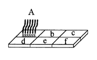
図3〜7はこの内、複数のプローブ配置場所の集合であるセンサアレイ部3を拡大した模式図である。図3はプローブ設置前の様子、図4,6はプローブ配置場所aにプローブAを設置中の様子、図5,7はプローブ配置場所a〜fにプローブA〜Fを設置した後の様子、を示す。
【0044】
図3のセンサアレイ部3の個々のプローブ配置場所a〜fにプローブを設置する。配置場所a〜fは互いに電気的に独立でき、それぞれ電極から電位が与えられるように配線されている。プローブ配置場所a〜fの順にプローブA〜Fをこの順に配置する場合、操作は次のようにして行う。
【0045】
(1)バイオチップ完成後、図1,2の試料導入口4からプローブ溶液を注入する。このとき、b〜fの電位を、aの電位よりマイナス側にしてプローブ溶液と各プローブ配置場所の間に電圧を印加する。この状態でプローブAを含むプローブ溶液をセンサアレイ部に流す。この操作により、図4,6のようにaにAが付着設置される。
【0046】
(2)ついで、a,c〜fの電位を、bの電位よりマイナス側にしてプローブ溶液と各プローブ配置場所の間に電圧を印加する。この状態でプローブBを含むプローブ溶液をセンサアレイ部に流す。この操作により、bにBが付着設置される。この際、aに設置されたAが若干流出する場合があるが、必要量のAを残存させることは容易である。
【0047】
(3)同様にして、c〜fまでの各プローブ配置場所にプローブを配置する。このようにして、図5,7のように、プローブ配置場所a〜fにプローブA〜Fが付着配置される。
【0048】
(4)採用する印加電圧やプローブ配置場所における電位は、実験等により最適値を適宜定めることができる。
【0049】
図4,5と図6,7とは、プローブA〜FがDNAであるときの、固定の様子の相違を推定したものである。
【0050】
図4,5は、帯電されたDNAの分子全体を利用して、プローブがプローブ設置場所に固定されているモデル図である。このような場合には、たとえば、上記(1)において、プローブ溶液とプローブ設置場所との間に、aの電位が0(ゼロ)V、b〜fがマイナス数百Vの電位となるように、電圧を印加する場合を例示できる。
【0051】
図6,7は、下記式
RSH+Au→AuSR+H++e−
(ここで、RはDNAのヌクレオチド構造、SHはチオール基を意味する。)を利用してプローブがプローブ設置場所に固定された場合を例示するモデル図である。たとえば、上記(1)において、プローブ溶液とプローブ設置場所との間に、aがプラスの電位、b〜fがマイナス電位になるように電圧に印加する場合を例示できる。
【0052】
このようにしてバイオチップを作成した結果、手作業によるプローブの配置作業を廃することができ、製造時間の短縮、工程の簡素化、対象物質の取扱いの容易化が実現できた。また、微小領域や物理的にアクセス困難な複雑な形状の領域にもプローブを配置することができ、所定の面積当たりに配することのできるプローブ配置場所の数を増大させることができ、物質検出装置を従来より小型化できた。
【0053】
なお、上記に開示した内容から、下記の付記に示した発明が導き出せる。
【0054】
(付記1) プラスまたはマイナスに帯電し得る2以上の種類の物質をそれぞれ所定の配置場所に配置する物質配置方法において、
当該所定の配置場所に他の配置場所とは異なる電位を与え、当該所定の配置場所に所定物質を電気的に付着せしめる、
物質配置方法。
【0055】
(付記2) プラスまたはマイナスに帯電し得る2以上の種類の物質が生体分子を含む、付記1に記載の物質配置方法。
【0056】
(付記3) プラスまたはマイナスに帯電し得る2以上の種類の物質が、タンパク質、DNAまたはヌクレオチド体を含む、付記1に記載の物質配置方法。
【0057】
(付記4) 前記タンパク質、DNAまたはヌクレオチド体が、ジスルフィド基またはチオール基を有し、ジスルフィド基やチオール基とヌクレオチド結合との間に−(CH2)n−結合(n=2〜15)を有する、付記3に記載の物質配置方法。
【0058】
(付記5) 配置場所がAuからなる、付記1〜4のいずれかに記載の物質配置方法。
【0059】
(付記6) プラスまたはマイナスに帯電し得る2以上の種類の物質をそれぞれ所定の配置場所に配置し、これらの物質との反応を利用して被検試料に含まれる物質を検出する物質検出装置の製造方法において、
それぞれ所定の配置場所に、プラスまたはマイナスに帯電し得る2以上の種類の物質を配置するに際し、当該所定の配置場所に他の配置場所とは異なる電位を与え、当該所定の配置場所に所定物質を電気的に付着せしめる、
物質検出装置の製造方法。
【0060】
(付記7) 前記プラスまたはマイナスに帯電し得る2以上の種類の物質を変質させる恐れのあるステップの後に所定の配置場所に所定物質を電気的に付着せしめる、付記6に記載の物質検出装置の製造方法。
【0061】
(付記8) 配置場所に蓋を取り付けた後に所定の配置場所に所定物質を電気的に付着せしめる、付記6に記載の物質検出装置の製造方法。
【0062】
(付記9) 前記物質検出装置がバイオチップである、付記6〜8のいずれかに記載の物質検出装置の製造方法。
【0063】
(付記10) プラスまたはマイナスに帯電し得る2以上の種類の物質が生体分子を含むものである、付記6〜9のいずれかに記載の物質検出装置の製造方法。
【0064】
(付記11) プラスまたはマイナスに帯電し得る2以上の種類の物質がタンパク質、DNAまたはヌクレオチド体を含むものである、付記6〜9のいずれかに記載の物質検出装置の製造方法。
【0065】
(付記12) 前記タンパク質、DNAまたはヌクレオチド体が、ジスルフィド基またはチオール基を有し、ジスルフィド基やチオール基とヌクレオチド結合との間に−(CH2)n−結合(n=2〜15)を有するものである、付記11に記載の物質検出装置の製造方法。
【0066】
(付記13) 配置場所がAuからなるものである、付記6〜12のいずれかに記載の物質検出装置の製造方法。
【0067】
【発明の効果】
本発明により、2以上の種類の物質、とりわけ生体分子を配置する物質配置方法および被検試料に含まれる物質、とりわけ生体分子を検出する物質検出装置の製造方法において、その時間の短縮、工程の簡素化、対象物質の取扱いの容易化を実現できる。また、所定の面積当たりに配することのできる配置場所の数を増大させることができ、物質検出装置を小型化できる。
【図面の簡単な説明】
【図1】バイオチップのセンサアレイ部分の概略平面図である。
【図2】図1のセンサアレイ部分の概略側断面図である。
【図3】センサアレイ部の拡大概略図である。
【図4】プローブをプローブ配置場に設置する様子を示すモデル図である。
【図5】プローブをプローブ設置場所に設置した様子を例示するモデル図である。
【図6】プローブをプローブ配置場に設置する様子を示す他のモデル図である。
【図7】プローブをプローブ設置場所に設置した様子を例示する他のモデル図である。
【符号の説明】
1 基板
2 プローブ配置場所
3 センサアレイ部
4 試料導入口[0001]
TECHNICAL FIELD OF THE INVENTION
The present invention relates to a method for arranging a substance, particularly a biomolecule, used for chemical analysis, diagnosing a disease, and drug development, and a substance contained in a test sample, particularly, a biomolecule for detecting a substance contained in a test sample by using the substance arranging method. The present invention relates to a method for manufacturing a device. More specifically, the present invention relates to a method for arranging a probe as a substance for detection on a biochip and a method for producing a biochip using the probe arranging method.
[0002]
[Prior art]
The Human Genome Project, which has been underway since the 1990s, is an attempt by each country to share all the human genetic code, and it was announced that a draft version was completed in the summer of 2000. In the future, it is expected that the progress of functional genomics and structural genomics will clarify the function of each part of the decoded human genome sequence information.
[0003]
The Human Genome Project has brought a major paradigm shift to science and technology and industry involved in life sciences. For example, diabetes is classified based on the condition that the blood sugar level is high, and the causes of the onset are classified as types I and II based on the degree of insulin production in the patient's body. Has been done.
[0004]
On the other hand, according to the Human Genome Project, it is involved in the control of the amino acid sequence structure of proteins such as enzymes and receptors involved in the regulation of the detection, synthesis and degradation of blood sugar and insulin, and the control of the abundance of such proteins All information on the DNA sequence of the gene is presented to us.
[0005]
Using such information, diabetes, a phenomenon in which blood sugar levels are not regulated properly, depends on which of the proteins involved in a series of processes such as detection, synthesis, degradation, etc. Should be able to make the appropriate diagnosis and treatment.
[0006]
In particular, the development of genomic drug discovery drugs for specific proteins based on the human genome sequence is being vigorously pursued in the pharmaceutical industry as a future business opportunity, and it is necessary to understand the state of a series of functionally related proteins. It is expected that the time will come when genomic drug discovery drugs will be administered to alleviate or cure symptoms.
[0007]
However, a technique for easily measuring the abundance of such a series of functionally related proteins is still being developed as a proteome analysis technique.
[0008]
Currently established methods use a combination of two-dimensional electrophoresis and mass spectrometry, which requires relatively large equipment and is used in clinical settings, such as hospital laboratories and beds. In order to grasp the patient's symptoms from the side, it is necessary to develop a simpler new technique.
[0009]
Under these circumstances, interest has been gathered in researches called micro-total analysis system (μ-TAS) and Lab-on-a-chip. In this method, a micrometer-sized groove (microchannel) is formed in a glass or silicon substrate of several centimeters square to form a fine device, in which chemical analysis and reaction are performed. Flowing liquid and gas samples through microscopic channels (several hundred μm to several μm wide) offers advantages such as reduced sample and waste volume, high-speed processing, and the possibility of miniaturizing even chemical plants. Therefore, application of this technology to the biotechnology field is expected. Μ-TAS is translated as “integrated chemical analysis system”, “microchemical / biochemical analysis system”, etc., and is a chemical analysis system with downsized sensors and analyzers, and is used in analytical chemistry laboratories. It integrates the functions of devices to be implemented on a chip.
[0010]
Above all, a biochip technology represented by a DNA chip (or DNA microarray) has attracted attention as an effective means for gene analysis. A biochip is a high-density array of many different probes consisting of biopolymers such as DNA and proteins, spotted on the surface of a substrate made of glass, silicon, plastic, etc. It is characterized in that testing of nucleic acids and proteins can be simplified in the field of therapy and the like (for example, see
[0011]
As the probe, for example, DNA or nucleotide is used. When an unknown DNA fragment is flown into such a biochip, the target DNA is captured by hybridization with a probe by utilizing the property of the DNA binding to the DNA complementary thereto. . If a fluorescent label is added to the unknown DNA in advance, the captured target is detected as a fluorescent signal from each spot on the biochip. It is possible to observe the status of tens of thousands of DNAs or RNAs at once.
[0012]
[Patent Document 1]
JP 2001-235468 A (paragraph numbers 0002 to 0009)
[0013]
[Non-patent document 1]
"Journal of American Chemical Society", 1997, Vol. 119, p. 8916-8920
[0014]
[Problems to be solved by the invention]
The biochip as described above has the following problems. First, for a specific biomolecule, it is necessary to align and spot a large number of different probes at a high density, and it is necessary to arrange a device for reacting each biomolecule of interest. In addition, since each of these containers has a size that can be seen with the naked eye, it has been an obstacle to miniaturization.
[0015]
Second, after forming a fine flow path pattern on the substrate using photolithography, a groove is formed by a method such as etching, and a lid is formed to form a flow path, such as μ-TAS. This method is generally used when producing a complicated biochip, but there is no means for attaching a DNA probe after sealing. For this reason, it is necessary to perform the operation of arranging the probes at a high density and spotting them during the process of producing the biochip, and there is a problem of affecting the DNA added during the process of producing the biochip.
[0016]
Still other objects and advantages of the present invention will become apparent from the following description.
[0017]
[Means for Solving the Problems]
According to one embodiment of the present invention, two or more types of biomolecules that can be positively or negatively charged are respectively arranged at predetermined locations, and are included in a test sample by utilizing a reaction with these biomolecules. In the method of manufacturing a biomolecule detecting device for detecting a biomolecule, when arranging two or more types of biomolecules that can be positively or negatively charged at a predetermined location, another location is placed at the predetermined location. And a method for manufacturing a biomolecule detecting device, which applies a potential different from the above and electrically attaches a predetermined biomolecule to the predetermined location.
[0018]
Two or more types of biomolecules that can be positively or negatively charged include proteins, DNAs, or nucleotides, and after attaching a lid to the location, electrically attaching the predetermined biomolecule to a predetermined location. preferable.
[0019]
According to the above method, in a method for manufacturing a biomolecule detecting device that detects biomolecules contained in a test sample by arranging two or more types of biomolecules, the time is shortened, the process is simplified, and the handling of the target substance is reduced. It can be made easier. Further, the number of arrangement locations that can be arranged per predetermined area can be increased, and the biomolecule detection device can be downsized.
[0020]
BEST MODE FOR CARRYING OUT THE INVENTION
Hereinafter, embodiments of the present invention will be described with reference to the drawings, examples, and the like. It should be noted that these drawings, examples, etc., and the description are merely examples of the present invention, and do not limit the scope of the present invention. It goes without saying that other embodiments can also belong to the category of the present invention as long as they conform to the gist of the present invention.
[0021]
The present invention has been completed as a result of a study focusing on the fact that biomolecules such as DNA are negatively charged. According to one aspect of the present invention, when two or more types of probes that can be negatively charged are arranged at predetermined probe locations on a biochip, the predetermined probe location is different from other probe locations. By applying different potentials, a predetermined probe is electrically attached to the predetermined probe location.
[0022]
FIG. 1 is a schematic plan view of a biochip, and FIG. 2 is a schematic side sectional view thereof. When a sample is detected (qualitative or quantitative analysis) using the biochip of FIGS. 1 and 2, the sample passes through the
[0023]
Conventionally, as a method of installing such a probe at a predetermined probe location on a biochip, a probe is manually installed at each probe location.
[0024]
On the other hand, according to the present invention, a probe is provided at a predetermined probe location on a biochip by utilizing a difference in Coulomb force when a potential difference is applied between the probe solution and the probe location. By merely pouring the probe solution onto the substrate where the probe is located, the probe can be attached to a predetermined probe location and not placed at other probe locations, and labor can be eliminated. Here, the probe solution includes not only a case where the probe itself is in a liquid state but also a solution in which the probe is diluted with a liquid medium. Dilution with a liquid medium is preferable because the concentration of a probe installed at a predetermined probe location at a predetermined area can be easily adjusted.
[0025]
In order to place a plurality of probes at different probe locations, it is necessary to provide a potential difference between the probe solution and the probe location each time a probe solution containing a different type of probe is used. A potential different from that of the other probe placement locations may be applied to the probe placement location to be used, and the predetermined probe may be electrically attached to the predetermined probe placement location.
[0026]
ADVANTAGE OF THE INVENTION According to the arrangement method concerning this invention, the structure of a biochip can be simplified and the complicated shape preparation step by photolithography etc. can be eliminated. Further, the size of the biochip can be reduced.
[0027]
In addition, since the conventional probe placement method cannot be performed after the lid is attached to the probe placement location, the probe placement must be performed before the lid is placed at the probe placement location. There was a risk that the biochip manufacturing step would alter the probe, but if the probe placement method of the present invention was employed, it would be sufficient to just pour the probe solution, and at any stage after the manufacturing step that might alter the probe. The probe can be attached and arranged, and the problem of probe deterioration can be solved. After the biochip is completed, the probe can be arranged. Further, by employing the probe arrangement method according to the present invention, the number of probe arrangement locations that can be arranged per predetermined area can be increased, and the size of the biochip can be reduced.
[0028]
Examples of the biomolecules used for the probe include proteins, DNAs, and nucleotides. Here, in the present invention, "nucleotide" means any one of the group consisting of oligonucleotides and polynucleotides or a mixture thereof. Such a substance is often negatively charged, and by hybridizing with a probe, a target substance is captured, and a technique of detecting a fluorescent signal using a fluorescent label can be used. This is because the effects of the present invention can be effectively exhibited. In addition, proteins, DNAs and nucleotides may be mixed. In addition, biomolecules include those derived from living organisms, processed ones, and synthesized molecules in addition to those derived from living organisms.
[0029]
When a probe is placed at a predetermined probe placement location on a biochip, it may be necessary to fix the probe so that the probe does not flow out when a sample is introduced. This fixing method can be arbitrarily selected without departing from the spirit of the present invention.
[0030]
For example, in the case of a protein, DNA or nucleotide, a known method such as a method of synthesizing a probe into which a disulfide group or a thiol group is introduced and bringing the probe into contact with a polished electrode surface can be employed. For example between the nucleotide binding and disulfide group and a thiol group - (CH 2) n - structure may be inserted a coupling called linker having the. The number of sensitive parts that can be immobilized at the probe location is often influenced by the type of the linker and the length of the bond. In general, when the number of CH 2 units decreases, the number of sensitive parts that can be fixed on the electrode tends to decrease. When the number is too large, the effect is lost and it is not necessary to increase the number unnecessarily. n = 2 to 15 is preferred.
[0031]
The material of the probe placement place can be arbitrarily determined according to the purpose, but Au is particularly preferable. This is because, when a biomolecule is used as a probe, it can be easily fixed to a probe placement location.
[0032]
In the biochip manufacturing method, when arranging two or more types of probes at respective predetermined probe placement locations, a different potential from the other probe placement locations is given to the predetermined probe placement location, and the predetermined An arrangement method of electrically attaching a predetermined probe to the probe arrangement location can be used.
[0033]
Accordingly, manual labor can be eliminated, the structure of the biochip can be simplified, and a complicated shape forming step by photolithography or the like can be eliminated. Further, the size of the biochip can be reduced. Further, after the manufacturing step that may deteriorate the probe, the probe can be arranged at an arbitrary stage, and the problem of the deterioration of the probe can be solved. After the biochip is completed, the probe can be arranged. The number of probe arrangement locations that can be arranged per predetermined area can be increased, and the size of the biochip can be reduced.
[0034]
In the above, the method of arranging probes and the method of manufacturing a biochip in the biochip have been described, but the present invention is not limited to these, and has a wider application range. In other words, without being limited to the concept of a probe or a biomolecule, generally, two or more types of substances that can be positively or negatively charged are respectively attached to predetermined locations, and a substance placement method or a positively or negatively charged substance is used. The present invention can be applied to a method of manufacturing a substance detection device that arranges two or more types of substances that can be used at predetermined locations and detects a substance contained in a test sample by using a reaction with these substances. it is conceivable that. That is, the ranges shown in the following supplementary notes are also included in the scope of the present invention.
[0035]
In the above description, "two or more types of substances" means that there are two or more substances to be detected and distinguished by the present invention, for example, "different types of DNA". The reaction used can be freely determined according to the purpose of use. The substance contained in the test sample can be analyzed qualitatively or quantitatively according to the purpose of use. That is, the substance detection according to the present invention includes detecting the presence of the specific substance and analyzing how much the specific substance is contained in the test sample.
[0036]
By adopting the method of manufacturing the substance arrangement and the substance detection device, it is possible to eliminate the manual work of arranging the substance at a predetermined location, thereby shortening the production time, simplifying the process, and facilitating the handling of the target substance. Can be realized.
[0037]
Further, since there is no restriction that the target substance cannot be placed after the lid is attached to the predetermined placement place as in the case of manual work, the predetermined placement can be performed at any time after the manufacturing step of altering the target substance. The target substance can be attached to the place. Even after the completion of the substance detection device, it is possible to perform the attachment and placement on the predetermined placement place.
[0038]
Further, since the probe can be easily arranged in a minute area or an area having a complicated shape which is physically difficult to access, the degree of freedom in designing the substance detecting device is increased. This makes it possible to increase the number of probe arrangement locations that can be arranged per predetermined area, and to reduce the size of the substance detection device as compared with the related art.
[0039]
The substance detection device realized by the present invention is, for example, in the case where hepatocytes switch intracellular glycogen metabolism in response to insulin receiving state in diabetes, for example, a series of protein interaction networks from insulin receptors to glycogenases. It can be used as a protein detection device that detects that a part is decreasing or increasing.
[0040]
By utilizing such a protein detection device, it becomes possible to capture the population of proteins, including post-translational modifications such as phosphorylation and sugar chain addition. Also, instead of diagnosing the phenomenon that appeared as a symptom as in the past as diabetes, for example, it is possible to grasp that a decrease in the function of a specific protein involved in the interaction network is causing the dysfunction of glucose metabolism. As a result, appropriate diagnosis and treatment corresponding to the cause of the dysfunction and verification of the treatment result can be performed. The same technique can be applied not only to diabetes but also to hypertension, hyperlipidemia, cancer (cell growth dysregulation) and other multifactorial diseases in general.
[0041]
【Example】
Next, embodiments of the present invention will be described in detail.
[0042]
[Example 1]
A biochip having the sensor array unit 3 as shown in FIGS. In FIGS. 1 and 2, the
[0043]
3 to 7 are schematic diagrams in which the sensor array unit 3 which is a set of a plurality of probe arrangement locations is enlarged. FIG. 3 shows a state before installing the probe, FIGS. 4 and 6 show a state where the probe A is installed at the probe arrangement location a, FIGS. 5 and 7 show a state after installing the probes A to F at the probe arrangement places a to f, Is shown.
[0044]
Probes are installed at individual probe arrangement locations a to f of the sensor array unit 3 in FIG. The arrangement places a to f can be electrically independent from each other, and are wired so that a potential is given from each electrode. When the probes A to F are arranged in the order of the probe arrangement locations a to f, the operation is performed as follows.
[0045]
(1) After completion of the biochip, a probe solution is injected from the
[0046]
(2) Next, the potentials of a, c to f are set to be more negative than the potential of b, and a voltage is applied between the probe solution and each probe arrangement location. In this state, the probe solution containing the probe B is caused to flow through the sensor array. By this operation, B is attached to b. At this time, A set in a may flow out a little, but it is easy to leave a necessary amount of A.
[0047]
(3) Similarly, a probe is arranged at each of the probe arrangement locations c to f. In this way, as shown in FIGS. 5 and 7, the probes A to F are attached to the probe placement locations a to f.
[0048]
(4) The optimum values of the applied voltage and the potential at the probe arrangement location can be appropriately determined by experiments and the like.
[0049]
FIGS. 4 and 5 and FIGS. 6 and 7 are obtained by estimating the difference in the state of immobilization when the probes A to F are DNA.
[0050]
FIGS. 4 and 5 are model diagrams in which a probe is fixed to a probe installation location by using the entire charged DNA molecule. In such a case, for example, in the above (1), the potential of a is set to 0 (zero) V and the potential of b to f is set to minus several hundred volts between the probe solution and the probe installation location. , A voltage is applied.
[0051]
6 and 7, the following formula RSH + Au → AuSR + H + + e -
(Here, R means the nucleotide structure of DNA and SH means a thiol group.) FIG. 7 is a model diagram illustrating a case where a probe is fixed to a probe installation location using a probe. For example, in the above (1), a case where a voltage is applied between the probe solution and the probe installation location such that a becomes a positive potential and b to f become negative potentials can be exemplified.
[0052]
As a result of preparing the biochip in this way, the manual probe placement operation can be eliminated, and the manufacturing time can be reduced, the process can be simplified, and the handling of the target substance can be facilitated. In addition, the probe can be arranged in a minute area or an area having a complicated shape that is physically difficult to access, and the number of probe arrangement places that can be arranged per a predetermined area can be increased. The device can be made smaller than before.
[0053]
From the contents disclosed above, the inventions shown in the following supplementary notes can be derived.
[0054]
(Supplementary Note 1) In a substance arranging method of arranging two or more types of substances that can be positively or negatively charged at respective predetermined locations,
Applying a different potential to the predetermined location to another location to electrically attach a predetermined substance to the predetermined location,
Material placement method.
[0055]
(Supplementary Note 2) The substance disposing method according to
[0056]
(Supplementary note 3) The substance arrangement method according to
[0057]
(Supplementary Note 4) The protein, DNA, or nucleotide body has a disulfide or thiol group, between the nucleotide binding and disulfide group and a thiol group - a bond (n = 2~15) - (CH 2)
[0058]
(Supplementary note 5) The substance disposing method according to any one of
[0059]
(Supplementary Note 6) A substance detection device that arranges two or more types of substances that can be positively or negatively charged at predetermined locations, and detects a substance contained in a test sample by using a reaction with these substances. In the manufacturing method of
When arranging two or more types of substances that can be positively or negatively charged at the respective predetermined locations, a different potential is applied to the predetermined location from the other locations, and the predetermined substance is applied to the predetermined location. To electrically attach the
A method for manufacturing a substance detection device.
[0060]
(Supplementary Note 7) The substance detection device according to Supplementary Note 6, wherein a predetermined substance is electrically attached to a predetermined location after the step of possibly altering two or more types of substances that can be positively or negatively charged. Production method.
[0061]
(Supplementary Note 8) The method for manufacturing a substance detection device according to Supplementary Note 6, wherein a predetermined substance is electrically attached to a predetermined location after the lid is attached to the location.
[0062]
(Supplementary note 9) The method for manufacturing a substance detection device according to any one of supplementary notes 6 to 8, wherein the substance detection device is a biochip.
[0063]
(Supplementary note 10) The method for manufacturing a substance detection device according to any one of Supplementary notes 6 to 9, wherein the two or more types of substances that can be positively or negatively charged include biomolecules.
[0064]
(Supplementary Note 11) The method for producing a substance detection device according to any one of Supplementary Notes 6 to 9, wherein the two or more types of substances that can be positively or negatively charged include proteins, DNAs, or nucleotides.
[0065]
(Supplementary Note 12) The protein, DNA, or nucleotide body has a disulfide or thiol group, between the nucleotide binding and disulfide group and a thiol group - a bond (n = 2~15) - (CH 2) n 12. The method for producing a substance detection device according to supplementary note 11, wherein the method comprises:
[0066]
(Supplementary Note 13) The method for manufacturing a substance detection device according to any one of Supplementary Notes 6 to 12, wherein the arrangement place is made of Au.
[0067]
【The invention's effect】
According to the present invention, in a method for arranging two or more types of substances, particularly a substance for arranging a biomolecule, and a method for manufacturing a substance detection apparatus for detecting a substance contained in a test sample, particularly, a biomolecule, the time can be reduced and the number of steps can be reduced. Simplification and easy handling of the target substance can be realized. Further, the number of arrangement places that can be arranged per predetermined area can be increased, and the substance detection device can be downsized.
[Brief description of the drawings]
FIG. 1 is a schematic plan view of a sensor array portion of a biochip.
FIG. 2 is a schematic side sectional view of a sensor array part of FIG. 1;
FIG. 3 is an enlarged schematic view of a sensor array unit.
FIG. 4 is a model diagram showing how a probe is installed in a probe placement field.
FIG. 5 is a model diagram illustrating a state where a probe is installed at a probe installation location.
FIG. 6 is another model diagram showing how a probe is installed in a probe placement field.
FIG. 7 is another model diagram illustrating a state where a probe is installed at a probe installation location.
[Explanation of symbols]
1
Claims (3)
それぞれ所定の配置場所に、プラスまたはマイナスに帯電し得る2以上の種類の生体分子を配置するに際し、当該所定の配置場所に他の配置場所とは異なる電位を与え、当該所定の配置場所に所定生体分子を電気的に付着せしめる、
生体分子検出装置の製造方法。A biomolecule detection device that arranges two or more types of biomolecules that can be positively or negatively charged at predetermined locations, and detects biomolecules contained in a test sample by utilizing a reaction with these biomolecules. In the manufacturing method of
When arranging two or more types of biomolecules that can be positively or negatively charged at each predetermined location, a different potential from the other location is applied to the predetermined location, and a predetermined potential is applied to the predetermined location. Electrically attach biomolecules,
A method for manufacturing a biomolecule detection device.
Priority Applications (1)
| Application Number | Priority Date | Filing Date | Title |
|---|---|---|---|
| JP2002339641A JP2004170372A (en) | 2002-11-22 | 2002-11-22 | Manufacturing method of biomolecule detecting apparatus |
Applications Claiming Priority (1)
| Application Number | Priority Date | Filing Date | Title |
|---|---|---|---|
| JP2002339641A JP2004170372A (en) | 2002-11-22 | 2002-11-22 | Manufacturing method of biomolecule detecting apparatus |
Publications (1)
| Publication Number | Publication Date |
|---|---|
| JP2004170372A true JP2004170372A (en) | 2004-06-17 |
Family
ID=32702548
Family Applications (1)
| Application Number | Title | Priority Date | Filing Date |
|---|---|---|---|
| JP2002339641A Pending JP2004170372A (en) | 2002-11-22 | 2002-11-22 | Manufacturing method of biomolecule detecting apparatus |
Country Status (1)
| Country | Link |
|---|---|
| JP (1) | JP2004170372A (en) |
Cited By (2)
| Publication number | Priority date | Publication date | Assignee | Title |
|---|---|---|---|---|
| JP2008151761A (en) * | 2006-03-31 | 2008-07-03 | Canon Inc | Target substance detecting method and target substance detecting kit |
| JP2010008096A (en) * | 2008-06-24 | 2010-01-14 | Kyoto Institute Of Technology | Substrate for microarray and its manufacturing method |
-
2002
- 2002-11-22 JP JP2002339641A patent/JP2004170372A/en active Pending
Cited By (2)
| Publication number | Priority date | Publication date | Assignee | Title |
|---|---|---|---|---|
| JP2008151761A (en) * | 2006-03-31 | 2008-07-03 | Canon Inc | Target substance detecting method and target substance detecting kit |
| JP2010008096A (en) * | 2008-06-24 | 2010-01-14 | Kyoto Institute Of Technology | Substrate for microarray and its manufacturing method |
Similar Documents
| Publication | Publication Date | Title |
|---|---|---|
| AU749884B2 (en) | Support for a method for determining an analyte and a method for producing the support | |
| JP5185335B2 (en) | Biochips for archiving biological samples and clinical analysis | |
| US8097421B2 (en) | Method for performing a multiplex immunoassay using label disassociation and an integrated substrate | |
| US20080020453A1 (en) | Analytical system based on porous material for highly parallel single cell detection | |
| AU2008208342A1 (en) | Analysis chip and analysis method | |
| Choudhuri | Microarrays in biology and medicine | |
| US20210016283A1 (en) | Ultrahigh throughput protein discovery | |
| EP1718411B1 (en) | A device for analysing an interaction between target and probe molecules | |
| US20030044320A1 (en) | High throughput screening micro array platform | |
| US8007744B2 (en) | Sample container for analyses | |
| JP2003232791A (en) | Probe solid-phase reaction array | |
| Schumacher et al. | Platform technologies for molecular diagnostics near the patient’s bedside | |
| WO2008003100A2 (en) | Make and use of surface molecules of varied densities | |
| CN108291251A (en) | System and method for foranalysis of nucleic acids | |
| US20070141576A1 (en) | Biological chip and use thereof | |
| JP2004170372A (en) | Manufacturing method of biomolecule detecting apparatus | |
| JP4130391B2 (en) | SUBJECT EVALUATION DEVICE, SUBJECT EVALUATION METHOD, AND SUBJECT EVALUATION DEVICE MANUFACTURING METHOD | |
| KR20040044151A (en) | Validated design for microarrays | |
| KR100813266B1 (en) | Method for removing air bubbles from hybridization solution of a microarray-cover slip assembly and a microarray kit for the same | |
| JP2004198140A (en) | Biomolecule detection method and device | |
| US7341865B1 (en) | Liquid delivery devices and methods | |
| Jain | Lab-on-a-chip and microarrays: discovery and development | |
| JP2004333255A (en) | Probe solid phase reaction array | |
| KR20100049881A (en) | Microarray with water repellent matreial pattern and manufacturing method of the same | |
| JP2009288160A (en) | Biosample analysis system, biosample analysis method, biosample pretreatment device, and biosample pretreatment method |
Legal Events
| Date | Code | Title | Description |
|---|---|---|---|
| A621 | Written request for application examination |
Free format text: JAPANESE INTERMEDIATE CODE: A621 Effective date: 20050708 |
|
| A977 | Report on retrieval |
Free format text: JAPANESE INTERMEDIATE CODE: A971007 Effective date: 20070522 |
|
| A131 | Notification of reasons for refusal |
Free format text: JAPANESE INTERMEDIATE CODE: A131 Effective date: 20070529 |
|
| A521 | Written amendment |
Free format text: JAPANESE INTERMEDIATE CODE: A523 Effective date: 20070723 |
|
| A02 | Decision of refusal |
Free format text: JAPANESE INTERMEDIATE CODE: A02 Effective date: 20080304 |
|
| A521 | Written amendment |
Free format text: JAPANESE INTERMEDIATE CODE: A523 Effective date: 20080418 |
|
| A911 | Transfer of reconsideration by examiner before appeal (zenchi) |
Free format text: JAPANESE INTERMEDIATE CODE: A911 Effective date: 20080514 |
|
| A912 | Removal of reconsideration by examiner before appeal (zenchi) |
Free format text: JAPANESE INTERMEDIATE CODE: A912 Effective date: 20080801 |