JP2004166436A - Electric fluid pump arrangement - Google Patents
Electric fluid pump arrangement Download PDFInfo
- Publication number
- JP2004166436A JP2004166436A JP2002331480A JP2002331480A JP2004166436A JP 2004166436 A JP2004166436 A JP 2004166436A JP 2002331480 A JP2002331480 A JP 2002331480A JP 2002331480 A JP2002331480 A JP 2002331480A JP 2004166436 A JP2004166436 A JP 2004166436A
- Authority
- JP
- Japan
- Prior art keywords
- motor
- rotation speed
- current
- control
- value
- Prior art date
- Legal status (The legal status is an assumption and is not a legal conclusion. Google has not performed a legal analysis and makes no representation as to the accuracy of the status listed.)
- Granted
Links
Images


Abstract
Description
【0001】
【発明の属する技術分野】
本発明は、ブラシレスDCモータを用いた電動流体ポンプ装置に関し、特に、センサレス駆動回路を用いて駆動する電動流体ポンプ装置に関する。
【0002】
【従来の技術】
ブラシレスDCモータをセンサレス駆動回路を用いて駆動する技術(特許文献1参照)がある。ここでは、モータへ流れる相電流を電流検出回路を用いて測定し、電流測定値のピーク値をサンプルホールドした後、このサンプルホールド値と設定値を比較して、サンプルホールド値が設定値以上でモータの脱調と判断してステップ駆動に入る技術が開示されている。
【0003】
また、電動流体ポンプにおいては、温度変化により、粘性が大きく変化する流体で任意の設定圧力を得る必要がある。これに対応するため、一般的には電流フィードバック(F/B)で電流をコントロールする方法が有る。
【0004】
【特許文献1】
特開平11−75389号公報(図1)
【0005】
【発明が解決しようとする課題】
上記技術においては、相電流毎のサンプルホールドをする為、脱調検出の応答性はよくなるが、電流検出部のノイズ(SWノイズ、EMI等)等で系がクリチカルとなり、ステップ駆動へ入る確率が増え、スムーズなモータ回転が得難い欠点がある。
【0006】
電流F/Bで電流をコントロールする場合、電流を設定値で一定に制御している状況で、負荷変動(異物、器差等)等が生じた時には、電流をF/Bしている為(PWM値が小さく)にモータ端子電圧が下がり、回転数が低下し、これにより誘起電圧が減少し、モータの特性に応じた回転数で脱調するという欠点をもっている。
【0007】
そこで、本発明は、センサレス駆動回路を用いて駆動するブラシレスDCモータを用いた電動流体ポンプ装置において、モータの脱調を防止することを課題とする。
【0008】
【課題を解決するための手段】
上記の課題を解決するため、本発明は、請求項1に記載したように、電流フィードバック制御によりブラシレスDCモータを駆動すると共に、モータの回転数が所定の回転数以下になった時、電流フィードバック制御から、回転数制御に切り替える制御装置を備えるようにした。
【0009】
これによれば、モータの回転数が所定の回転数より大きい場合には、電流フィードバック制御によりモータが制御される。また、異物の影響などで負荷変動が生じたとき、電流フィードバック制御の影響でモータ電圧が下がり回転数が下がるような場合、モータの制御が回転数制御に切り替わる。
【0010】
また、請求項2に記載したように、請求項1において、前記ブラシレスDCモータを3相モータとし、制御装置は、モータの通電を、電流フィードバック制御を行っているときは120度通電に、回転数制御を行っているときは、例えば180度通電などのラップ通電に、切り替えるようにした。
【0011】
これによれば、電流フィードバック制御の場合は120度通電となり、各相のモータ巻線のいずれか1相のみ通電が行われる。また、回転数制御を行っているときはラップ通電となり、複数の相に同時に通電される。
【0012】
また、請求項3に記載したように、請求項1において、所定の回転数は、脱調限界値の回転数もしくは脱調限界値の回転数に所定のマージンを加えた値とするようにした。
【0013】
これによれば、電流フィードバック制御から回転数制御に移行するタイミングがモータの脱調限界位置に近い値となる。
【0014】
また、請求項4に記載したように、請求項1において、電流フィードバック制御は、モータ電流値と指令値との偏差をなくすよう制御するものであり、回転数制御は現在のモータの回転数と設定回転数との偏差をなくすよう制御するものであるようにした。
【0015】
これによれば、電流フィードバック制御時には、モータに流れる電流値が指令値と等しくなるよう、モータが制御される。また、回転数制御時には、モータの回転数が設定回転数に等しくなるようにモータが制御される。
【0016】
また、請求項5に記載したように、請求項1において、電流フィードバック制御は、モータ電流値と指令値との偏差をなくすような出力デューティを演算しモータを制御するものであり、回転数制御はモータ電流値と指令値との偏差をなくすような出力デューティを演算し、この出力デューティに所定の設定値を加えた値にてモータを制御するものであるようにした。
【0017】
これによれば、電流フィードバック制御時には、モータに流れる電流値が指令値と等しくなるような出力デューティが演算され、この値にてモータが制御される。また、回転数制御時には、モータに流れる電流値が指令値と等しくなるような出力デューティが演算され、この値に所定の設定値を加えた値にてモータが制御される。このため、電流フィードバック制御時の時に対して、出力デューティが増加し、回転数が増加する方向で調整される。
【0018】
また、請求項6に記載したように、請求項4又は5において、電流フィードバック制御から回転数制御への移行時のモータ回転数より、現在のモータ回転数が大きくなった場合、電流フィードバック制御に戻すようにした。
【0019】
これによれば、モータ回転数の落ち込みが回復した段階で速やかに電流フィードバック制御に戻される。
【0020】
【発明の実施の形態】
以下、本発明の実施の形態を図面を参照して説明する。
【0021】
図1に、本発明を車載用の電動オイルポンプに適用したシステムの制御ブロック図を示す。オイルポンプ1は直流ブラシレスモータであるモータ2により駆動される。モータ2は制御装置3内のセンサレス駆動回路5の信号を電力増幅回路6により増幅した電力で駆動される。センサレス駆動回路5はマイクロプロセッシングユニット(MPU)4により演算されたパルス幅変調(PWM)デューティ出力を受け、モータ2を駆動する。このとき、センサレス駆動回路5はモータが停止中又は始動中は低レベル出力となり、モータが正常動作中はモータ電気周期で変化する回転信号出力OUT−FGを出力する。
【0022】
MPU4は回転信号出力OUT−FGを受け、内部の演算部13にてモータの起動時間、起動回数、及びモータの回転数を演算する。また、演算部13は、モータの回転数と予め設定してある設定回転数との偏差を演算し、セレクタ15にモータ回転数と回転数偏差ゼロにするように求めた目標値をPWM信号に変換した信号(モータ回転数制御信号)を出力する。
【0023】
また、MPU4は、目標電流変換部7、モータ電源電流/Duty演算部8、PWMDuty出力演算部10、演算部9を備える。目標電流変換部7には、外部から目標電流指令値SIが与えられる。この目標電流指令値SIは、目標電流値を示すものであり、外部のシステムから与えられ、通信により受け取るためにパルス波形で送られて受信している。目標電流変換部7はこのパルスを目標電流値に変換する。モータ電源電流/Duty演算部8には、モータ2に流れる電流値が与えられる。モータ電源電流/Duty演算部8は、この電流値をデューティ比で割って、デューティ比あたりのモータに流れる電流値を算出する。演算部9は、目標電流値とデューティ比あたりのモータに流れる電流値を受け、デューティ比あたりのモータに流れる電流値をエラー信号として、このエラー信号が少なくなるように目標電流値を修正し、PWMDuty出力演算部10に送る。PWMDuty出力演算部10は受け取った目標電流値をPWM信号に変換し、モータ電流制御信号として、センサレス駆動回路5に向けて送る。
【0024】
MPU4は、更に、電源電圧補正手段11、セレクタ12,15を備える。電源電圧補正手段11は、モータ2に与える電源電圧+Bを測定し、電源電圧に応じた起動デューティ比を計算する。セレクタ12は、モータ2の起動時のみ、電源電圧に応じた起動デューティ比になるよう、PWMDuty出力演算部10からセンサレス駆動回路5に送られる信号を切り替える。即ち、起動時は起動デューティ比の信号、その他のときはモータ電流制御信号が送られる。また、セレクタ15は、セレクタ12からの信号と、演算部13からの信号を切り替える。具体的には、セレクタ15は、モータ電流制御信号が送られているとき(モータ電流制御時)には、現在のモータの回転数が、予め定められた最小回転数以下となったときにモータ回転数制御信号を送るよう切り替え、モータ回転数制御信号が送られているとき(モータ回転数制御時)には、回転数制御に移行した時の指令値(回転数)が現在の指令値(回転数)以下となったときにモータ電流制御信号を送るよう切り替える。
【0025】
尚、MPU4は、演算部13で演算した起動時間が規格外か正常かを演算部14で演算して、外部に状態信号として出力している。もし、起動時間が規格外であれば、モータに異常が発生していることが外部から判断できる。
【0026】
図2に本発明を実施する場合の具体的な回路図を示す。
【0027】
メインのバッテリPbは車載用の電源で、イグニッションスイッチIG−SWを介してECU22、リレーRLY1を介して制御装置3の+B端子にそれぞれ接続されている。ECU22はリレーRLY1を制御すると共に、モータ2の目標電流指令値SIを演算し、制御装置3へ送信する機能を持っている。また、ECU22は制御装置3からの状態信号STを受けて、故障診断を行う。ECU22がリレーRLY1をオンとすると、制御装置3の+B端子に電力が供給され、定電圧電源5V Reg.が電圧Vccを供給する。MPU4とセンサレス駆動回路5は、電圧Vccを受けて動作を開始する。
【0028】
センサレス駆動回路5は、株式会社東芝製のICで、3相全波ブラシレスDCモータセンサレスコントローラTB9060FNを使用している。このICは、PWM制御信号と、モータの回転位置信号WAVEを受けて、3相の全波ブラシレスDCモータを駆動できるものである。また、過電流保護機能を有し、回転信号出力OUT−FGを出力できるものである。回転信号出力OUT−FGからは、停止中及び始動中はロー出力で、正常動作中はモータの電気周期で変化する信号が出力される。
【0029】
このセンサレス駆動回路5の3相出力(上側:UP、VP、WP,下側:UN、VN、WN)は、プリドライバである電力増幅回路6を介して、トランジスタTR1〜6を制御する。トランジスタTR1、TR2、TR3はそれぞれモータ2のU相、V層、W相の上側の切り替えを担当し、抵抗Rを介して+B端子に接続されている。トランジスタTR4、TR5、TR6はそれぞれモータ2のU相、V層、W相の下側の切り替えを担当し、グランドGNDに接地されている。センサレス駆動回路5の3相出力を切り替えることで、モータ2の各相の巻線への通電が順次切り替えられるので、モータが回転する。
【0030】
抵抗Rはモータ2に流れる電流を検出する。増幅器18は抵抗Rの両端に電圧を増幅し、この値をMPU4のIR端子に与える。過電流検出回路OCは増幅器18の出力を受け、モータ2に通常流れうる電流値を越えて電流が流れていることを検出し、MPU4の過電流検出端子OCへの出力を切り替える。異常電流検出回路SCは増幅器18の出力を受け、モータ2がショートしている場合に流れる電流値に達していることを検出し、MPU4の異常電流検出端子SCへの出力を切り替える。図示しないが、MPU4は、過電流が流れたとき、モータの電源電流の演算を調整したり、電流の積算値の応じて加熱保護を行ったりする。また、MPU4は異常電流が流れたとき、センサレス駆動回路5への制御信号を電流が流れないように切り替えたりしている。ダイオードD1は過電流検出回路OC及び異常電流検出回路SCと、センサレス駆動回路5に接続され、過電流もしくは異常電流が流れたとき、センサレス駆動回路5の過電流保護用の端子OCの電圧を切り替え、センサレス駆動回路5の過電流保護が働くように設置されている。
【0031】
MPU4は入力インターフェースを介して目標電流指令値SIをECU22から受け取る。また、出力インターフェースを介して状態信号STをECU22に出力する。MPU4は図3以降のフローチャートに沿って動作する。
【0032】
図3はMPU4のメインルーチンのフローチャートである。まず、MPU4が起動すると、ステップ30にて、ECU22からの目標電流指令値SIを受け取る。次に、モータ電源電流認識ルーチン(ステップ31)、電源電圧認識ルーチン(ステップ32)、脱調判定ルーチン(ステップ33)、制御モータ判定ルーチン(ステップ34)、及び出力PWM Duty決定処理ルーチン(ステップ35)を順に実行し、ステップ30に戻る。以後、ステップ30から35を繰り返し実行する。
【0033】
モータ電源電流認識ルーチンは、MPU4のIR端子の信号を読み、モータ2に流れるモータ電源電流IRを測定する。
【0034】
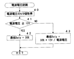
電源電圧認識ルーチンは、図4に示すように、ステップ40にて電源電圧+Bの値をA/D変換により取得する。次に、読み取った電源電圧値が12V以上かどうかをステップ41にて判定し、12V以上であればステップ42にて最低デューティの値を30%に設定する。この最低デューティの値は後述の出力PWMDuty決定処理ルーチン内で使用する。一方、電源電圧値が12V未満であればステップ43にて最低デューティの値を30%×12V/電源電圧に設定する。この処理により、図5に示すように、電源電圧の値が高い時には、最低デューティが30%となり、電源電圧の値が低い時には、最低デューティをより高めに設定し、電圧の低下による脱調を起きにくくしている。
【0035】
脱調判定ルーチンは、図6に示すように、ステップ50により脱調モードに応じて処理を分けて実行している。
【0036】
初期状態では、脱調モードは「停止」モードとなっている。脱調モードが「停止」モードもしくは「再起動」モードにあるときはステップ51以下が実行される。したがって、初回はステップ51以下が実行される。ここでは、ステップ51にて、起動開始から回転信号出力OUT−FGが立ち上がるまでの時間を監視し、測定する。通常、モータが正常な場合は、起動開始から回転信号出力OUT−FGが立ち上がるまでの時間はある範囲内となるはずである。この時間が正常な範囲にあるかどうかをステップ52にて判断し、正常であればステップ53にて脱調モードを「定常状態」モードに変更する。一方、ステップ52にて起動開始から回転信号出力OUT−FGが立ち上がるまでの時間が異常であった場合には、ステップ55にて脱調モードを「脱調確定状態」モードに変更し、ステップ56にてタイマーを停止し、モータが回転しないようにする。
【0037】
脱調モードが「定常状態」モードに変更された場合、次回にこの脱調判定ルーチンが処理される場合は、ステップ57以降が実行される。ステップ57ではモータの回転数の範囲が規定の上限値を上回るか、もしくは規定の下限値を下回るかで異常を監視する。モータの回転数は回転信号出力OUT−FGから測定できる。モータの回転数が下限値から上限値の範囲内であればステップ58にて正常であると判定しルーチンを抜ける。モータの回転数が下限値以下または上限値以上であればステップ59にて脱調モードを「脱調確定状態」モードに変更する。
【0038】
脱調判定ルーチンが実行されるとき、脱調モードが「脱調確定状態」モードであった場合、ステップ60にて再起動回数が設定値未満がどうかを判断する。再起動回数は、MPU4が動作を開始してから、モータを再起動した回数をカウントしているものである。この再起動回数が所定値(例えば3回)未満であれば、ステップ61にて一定の時間だけ待機し、その後、ステップ62にて、脱調モータを「再起動」に変更し、モータ状態フラグを「モータ起動状態」に設定する。このモータ状態フラグは後述の出力PWM Duty決定処理ルーチン内で使用される。これにより、次回、脱調判定ルーチンが実行されるときには、前述のステップ51以降が実行され、再度起動時の処理が行われる。再起動回数が所定値に達すると、ステップ64にて脱調モードを「脱調不良状態」に変更し、ルーチンを抜ける。脱調判定ルーチンが実行されるとき、脱調モードが「脱調不良状態」であれば、何も処理を行わない。
【0039】
出力PWM Duty決定処理ルーチンは、図7に示すように、モータ状態フラグに応じて処理を切り替えている。モータ状態フラグとしては、「モータ停止状態」、「モータ起動状態」、「モータ定常状態」があり、それぞれ、ステップ71の停止状態処理、ステップ72の起動状態処理ルーチン、ステップ73の定常状態処理ルーチンが実行される。モータ状態フラグは初期値として「モータ起動状態」が設定される。したがって、初回にこのルーチンが実行されるときは、ステップ72の起動状態処理ルーチンが実行される。
【0040】
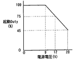
起動状態処理ルーチンは、図8に示すように、まずステップ80にて、電源電圧に応じて処理を分ける。電源電圧が9V以下であれば、ステップ81にて、起動デューティを100%に設定する。電源電圧が9Vを超えていれば、起動デューティを100%×9V/電源電圧とし、電源電圧があがるにつれ起動デューティを下げるように起動デューティを設定する。起動デューティは図9に示すようになる。この後で、ステップ83にて、出力デューティレジスタ設定を行い、ステップ84にてタイマーをスタートさせる。このタイマーが終了したとき、モータ状態を「モータ定常状態」に切り替える。この処理により、起動状態においては、起動デューティに応じてモータが回転する。
【0041】
定常状態処理ルーチンは、図10に示すように、ステップ90にて制御モードに応じて処理を切り替える。制御モードには、「モータ電流制御」と「モータ回転数制御」がある。
【0042】
モータ電流制御モードでは、ステップ91にて現在のモータの回転数が所定の最小回転数以下かどうかを判断し、所定の最小回転数以下であれば、ステップ92にて制御モードを「モータ回転数制御」に変更し、ステップ93にてモータへの通電の仕方を120度通電から180度通電に切り替える。この後、ステップ94にて現在の指令値を保存する。モータの通電の仕方が180度通電となると、モータの各相の通電信号の切り替わり時に相と相で重なる部分が作られ(ラップ通電)、モータが安定して回転するようになる。尚、このラップ通電は、180度通電以外でもよい。
【0043】
モータ回転数制御モードでは、回転数制御移行時の指令値が現在の指令値以下であるか否かをステップ96にて判断し、現在の指令値以下であれば、ステップ97にて制御モードを「モータ電流制御」に変更し、ステップ98にてモータへの通電の仕方を180度通電から120度通電に切り替える。
【0044】
モータ電流制御モードの場合も、モータ回転数制御モードの場合も最後にステップ95のPWM Duty演算&設定ルーチンを実行する。
【0045】
PWM Duty演算&設定ルーチンは図11に示すように、ステップ100により、制御モードに応じて処理を切り替えている。モータ電流制御モードでは、ステップ101にて、モータ電流値と指令値との偏差から出力デューティを演算する。したがって、電流フィードバック制御となり、温度変化により流体の粘性が大きく変化する場合でも任意の設定圧力を得ることができる。モータ回転数制御モードでは、ステップ102にて、現在の回転数と設定回転数との偏差から出力デューティを演算する。したがって、モータ回転数の落ち込みを防止でき、脱調しにくくなる。次に、前述の電源電圧認識ルーチンで設定した最低デューティを用い、ステップ103にて出力デューティが最低デューティ以下であるかどうかを判断し、出力デューティが最低デューティ以下であれば、ステップ104にて出力デューティを最低デューティに置き換えて、出力デューティが最低デューティを下回らないように補正する。次にステップ105にて出力デューティのレジスタ設定を行う。
【0046】
このように、モータの回転数が所定の回転数より大きい場合には、電流フィードバック制御によりモータが制御されるので、温度変化により流体の粘性が大きく変化する場合でも任意の設定圧力を得ることができる。また、異物の影響などで負荷変動が生じたとき、電流フィードバック制御の影響でモータ電圧が下がり回転数が下がるような場合でも、モータの制御が回転数制御に切り替わるため、モータの回転数が落ち込むことがなく、モータの脱調が防止できる。
【0047】
図12はPWM Duty演算&設定ルーチンの別の実施例である。ここでは、図11のステップ100から102の部分が異なっている。図12において、ステップ106にて、モータ電流値と指令値との偏差から出力デューティを演算する。次に、制御モードが「モータ回転数制御」の場合は、出力デューティに所定の設定値だけ上乗せする。よって、制御モードが「モータ回転数制御」の場合、出力デューティがモータ電流制御の場合よりも大きくなり、モータの回転数を上げる方向に傾く。
【0048】
【発明の効果】
以上説明したように、請求項1に記載した発明によれば、モータの回転数が所定の回転数より大きい場合には、電流フィードバック制御によりモータが制御されるので、温度変化により流体の粘性が大きく変化する場合でも任意の設定圧力を得ることができる。また、異物の影響などで負荷変動が生じたとき、電流フィードバック制御の影響でモータ電圧が下がり回転数が下がるような場合でも、モータの制御が回転数制御に切り替わるため、モータの回転数が落ち込むことがなく、モータの脱調が防止できる。
【0049】
また、請求項2に記載した発明によれば、電流フィードバック制御の場合は120度通電となり、各相のモータ巻線のいずれか1相のみ通電が行われるため、応答性が良くなる。また、回転数制御を行っているときはラップ通電となり、複数の相に同時に通電されるため、脱調しにくくなる。
【0050】
また、請求項3に記載した発明によれば、電流フィードバック制御から回転数制御に移行するタイミングがモータの脱調限界位置に近い値となり、効率的にモータを回転させうる。
【0051】
また、請求項4に記載した発明によれば、電流フィードバック制御時には、モータに流れる電流値が指令値と等しくなるよう、モータが制御され、温度変化により流体の粘性が大きく変化する場合でも任意の設定圧力を得ることができる。また、回転数制御時には、モータの回転数が設定回転数に等しくなるようにモータが制御され、モータの回転数が落ち込むことがなく、モータの脱調が防止できる。
【0052】
また、請求項5に記載した発明によれば、電流フィードバック制御時には、モータに流れる電流値が指令値と等しくなるような出力デューティが演算され、この値にてモータが制御される。また、回転数制御時には、モータに流れる電流値が指令値と等しくなるような出力デューティが演算され、この値に所定の設定値を加えた値にてモータが制御される。このため、電流フィードバック制御時の時に対して、出力デューティが増加し、回転数が増加する方向で調整される。よって、モータの脱調が発生しにくくなる。
【0053】
また、請求項6に記載した発明によれば、モータ回転数の落ち込みが回復した段階で速やかに電流フィードバック制御に戻されるので、効率よくモータを制御できる。
【図面の簡単な説明】
【図1】本発明の一実施形態における車載用の電動オイルポンプに適用したシステムの制御ブロック図である。
【図2】本発明の一実施形態における車載用の電動オイルポンプに適用したシステムの回路図である。
【図3】図2におけるMPU4のメインルーチンのフローチャートである。
【図4】電源電圧認識ルーチンのフローチャートである。
【図5】最低デューティの設定方法を示すグラフである。
【図6】脱調判定ルーチンのフローチャートである。
【図7】出力PWM Duty決定処理ルーチンのフローチャートである。
【図8】起動状態処理のフローチャートである。
【図9】起動デューティの設定方法を示すグラフである。
【図10】定常状態処理ルーチンのフローチャートである。
【図11】PWM Duty演算&設定ルーチンのフローチャートである。
【図12】PWM Duty演算&設定ルーチンの別の実施例のフローチャートである。
【符号の説明】
1 オイルポンプ
2 モータ(直流ブラシレスモータ)
3 制御装置
4 マイクロプロセッシングユニット(MPU)
5 センサレス駆動回路
6 電力増幅回路(プリドライバ)
7 目標電流変換部
8 モータ電源電流/Duty演算部
9,13 演算部
10 PWMDuty出力演算部
11 電源電圧補正手段
12,15 セレクタ
18 増幅器
22 ECU
IG−SW イグニッションスイッチ
OC 過電流検出回路
OUT−FG 回転信号出力
SC 異常電流検出端子
SI 目標電流指令値
ST 状態信号
TR1〜6 トランジスタ
WAVE モータの回転位置信号[0001]
TECHNICAL FIELD OF THE INVENTION
The present invention relates to an electric fluid pump device using a brushless DC motor, and particularly to an electric fluid pump device driven using a sensorless drive circuit.
[0002]
[Prior art]
There is a technique for driving a brushless DC motor using a sensorless drive circuit (see Patent Document 1). Here, the phase current flowing to the motor is measured using a current detection circuit, the peak value of the measured current value is sampled and held, and the sample hold value is compared with the set value. There is disclosed a technique for determining that the motor is out of synchronization and entering step driving.
[0003]
Further, in the electric fluid pump, it is necessary to obtain an arbitrary set pressure with a fluid whose viscosity changes greatly due to a temperature change. In order to cope with this, there is generally a method of controlling current by current feedback (F / B).
[0004]
[Patent Document 1]
JP-A-11-75389 (FIG. 1)
[0005]
[Problems to be solved by the invention]
In the above technique, since the sample and hold is performed for each phase current, the responsiveness of step-out detection is improved, but the system becomes critical due to noise (SW noise, EMI, etc.) of the current detection unit and the likelihood of entering step drive. The disadvantage is that it is difficult to obtain smooth motor rotation.
[0006]
In the case where the current is controlled by the current F / B, the current is controlled by the F / B when a load change (foreign matter, instrument difference, etc.) occurs in a situation where the current is controlled to be constant at a set value ( The motor terminal voltage decreases (the PWM value is small), the rotational speed decreases, and the induced voltage decreases. As a result, the motor loses synchronism at the rotational speed according to the characteristics of the motor.
[0007]
Therefore, an object of the present invention is to prevent motor step-out in an electric fluid pump device using a brushless DC motor driven using a sensorless drive circuit.
[0008]
[Means for Solving the Problems]
In order to solve the above-mentioned problem, the present invention drives a brushless DC motor by current feedback control, and performs current feedback when the number of rotations of the motor becomes equal to or lower than a predetermined number of rotations. A control device for switching from control to rotation speed control is provided.
[0009]
According to this, when the rotation speed of the motor is higher than the predetermined rotation speed, the motor is controlled by the current feedback control. In addition, when a load fluctuation occurs due to the influence of a foreign object or the like, and the motor voltage decreases due to the influence of the current feedback control and the rotational speed decreases, the control of the motor is switched to the rotational speed control.
[0010]
Also, as described in
[0011]
According to this, in the case of the current feedback control, 120-degree energization is performed, and only one of the motor windings of each phase is energized. In addition, when the rotation speed control is being performed, the lap is energized, and the plurality of phases are energized simultaneously.
[0012]
Further, as described in
[0013]
According to this, the timing of shifting from the current feedback control to the rotation speed control becomes a value close to the step-out limit position of the motor.
[0014]
Further, as described in
[0015]
According to this, at the time of the current feedback control, the motor is controlled such that the current value flowing through the motor becomes equal to the command value. At the time of rotation speed control, the motor is controlled such that the rotation speed of the motor is equal to the set rotation speed.
[0016]
According to a fifth aspect of the present invention, in the first aspect, the current feedback control is for controlling the motor by calculating an output duty to eliminate a deviation between the motor current value and the command value. Calculates the output duty to eliminate the deviation between the motor current value and the command value, and controls the motor with a value obtained by adding a predetermined set value to the output duty.
[0017]
According to this, at the time of the current feedback control, an output duty is calculated such that a current value flowing through the motor becomes equal to the command value, and the motor is controlled with this value. Further, at the time of rotation speed control, an output duty is calculated such that a current value flowing through the motor becomes equal to a command value, and the motor is controlled by a value obtained by adding a predetermined set value to this value. For this reason, the output duty is increased and the rotation speed is adjusted in a direction to increase as compared with the case of the current feedback control.
[0018]
In addition, as described in
[0019]
According to this, when the fall of the motor speed is recovered, the control is immediately returned to the current feedback control.
[0020]
BEST MODE FOR CARRYING OUT THE INVENTION
Hereinafter, embodiments of the present invention will be described with reference to the drawings.
[0021]
FIG. 1 shows a control block diagram of a system in which the present invention is applied to a vehicle-mounted electric oil pump. The
[0022]
The
[0023]
Further, the
[0024]
The
[0025]
In addition, the
[0026]
FIG. 2 shows a specific circuit diagram for implementing the present invention.
[0027]
The main battery Pb is a vehicle-mounted power supply, and is connected to the
[0028]
The
[0029]
The three-phase outputs (upper side: UP, VP, WP, lower side: UN, VN, WN) of the
[0030]
The resistor R detects a current flowing through the
[0031]
The
[0032]
FIG. 3 is a flowchart of the main routine of the
[0033]
In the motor power supply current recognition routine, the signal of the IR terminal of the
[0034]
In the power supply voltage recognition routine, as shown in FIG. 4, in
[0035]
In the step-out determination routine, as shown in FIG. 6, the processing is separately executed in
[0036]
In an initial state, the step-out mode is a “stop” mode. When the step-out mode is in the "stop" mode or the "restart" mode, steps 51 and subsequent steps are executed. Therefore, step 51 and subsequent steps are executed for the first time. Here, in step 51, the time from the start of activation until the rotation signal output OUT-FG rises is monitored and measured. Normally, when the motor is normal, the time from the start of startup to the rise of the rotation signal output OUT-FG should be within a certain range. At
[0037]
When the step-out mode is changed to the “steady state” mode, when the step-out determination routine is processed next time, the steps after
[0038]
When the out-of-step determination routine is executed, if the out-of-step mode is the “out-of-step confirmation state” mode, it is determined in
[0039]
As shown in FIG. 7, the output PWM duty determination processing routine switches processing according to the motor state flag. The motor state flags include a "motor stopped state", a "motor started state", and a "motor steady state". The stopped state processing in
[0040]
In the activation state processing routine, as shown in FIG. 8, first, in
[0041]
In the steady state processing routine, as shown in FIG. 10, the processing is switched in
[0042]
In the motor current control mode, it is determined whether or not the current motor rotation speed is equal to or less than a predetermined minimum rotation speed in step 91, and if not, the control mode is changed to "motor rotation speed" in step 92. Control ”, and in step 93, the method of energizing the motor is switched from 120-degree energization to 180-degree energization. Thereafter, in
[0043]
In the motor speed control mode, it is determined in
[0044]
In both the motor current control mode and the motor speed control mode, the PWM duty calculation & setting routine of
[0045]
As shown in FIG. 11, the processing of the PWM duty calculation & setting routine is switched in
[0046]
As described above, when the rotation speed of the motor is higher than the predetermined rotation speed, the motor is controlled by the current feedback control. Therefore, even when the viscosity of the fluid greatly changes due to a temperature change, an arbitrary set pressure can be obtained. it can. In addition, when the load fluctuates due to the influence of foreign matter or the like, even if the motor voltage is reduced due to the influence of the current feedback control and the rotational speed is reduced, the motor control is switched to the rotational speed control. And motor step-out can be prevented.
[0047]
FIG. 12 shows another embodiment of the PWM duty calculation & setting routine. Here, steps 100 to 102 in FIG. 11 are different. In FIG. 12, in step 106, the output duty is calculated from the deviation between the motor current value and the command value. Next, when the control mode is “motor rotation speed control”, a predetermined set value is added to the output duty. Therefore, when the control mode is “motor rotation speed control”, the output duty becomes larger than in the case of motor current control, and the output duty is inclined in a direction to increase the rotation speed of the motor.
[0048]
【The invention's effect】
As described above, according to the first aspect of the invention, when the rotation speed of the motor is higher than the predetermined rotation speed, the motor is controlled by the current feedback control. An arbitrary set pressure can be obtained even in the case of a large change. In addition, when the load fluctuates due to the influence of foreign matter or the like, even if the motor voltage is reduced due to the influence of the current feedback control and the rotational speed is reduced, the motor control is switched to the rotational speed control. And motor step-out can be prevented.
[0049]
According to the second aspect of the present invention, in the case of the current feedback control, the current is applied at 120 degrees, and only one of the motor windings of each phase is energized, so that the responsiveness is improved. In addition, when the rotation speed is controlled, the lap is energized, and the current is simultaneously applied to a plurality of phases.
[0050]
Further, according to the third aspect of the invention, the timing of shifting from the current feedback control to the rotation speed control becomes a value close to the step-out limit position of the motor, and the motor can be rotated efficiently.
[0051]
Further, according to the invention described in
[0052]
According to the fifth aspect of the invention, at the time of current feedback control, an output duty is calculated such that a current value flowing through the motor becomes equal to the command value, and the motor is controlled by this value. Further, at the time of rotation speed control, an output duty is calculated such that a current value flowing through the motor becomes equal to a command value, and the motor is controlled by a value obtained by adding a predetermined set value to this value. For this reason, the output duty is increased and the rotation speed is adjusted in a direction to increase as compared with the case of the current feedback control. Therefore, the step-out of the motor hardly occurs.
[0053]
Further, according to the invention described in
[Brief description of the drawings]
FIG. 1 is a control block diagram of a system applied to an on-vehicle electric oil pump according to an embodiment of the present invention.
FIG. 2 is a circuit diagram of a system applied to an on-vehicle electric oil pump according to an embodiment of the present invention.
FIG. 3 is a flowchart of a main routine of an
FIG. 4 is a flowchart of a power supply voltage recognition routine.
FIG. 5 is a graph showing a method of setting a minimum duty.
FIG. 6 is a flowchart of a step-out determination routine.
FIG. 7 is a flowchart of an output PWM duty determination processing routine.
FIG. 8 is a flowchart of a startup state process.
FIG. 9 is a graph showing a setting method of a start duty.
FIG. 10 is a flowchart of a steady state processing routine.
FIG. 11 is a flowchart of a PWM duty calculation & setting routine.
FIG. 12 is a flowchart of another embodiment of a PWM duty calculation & setting routine.
[Explanation of symbols]
1
3
5
7 Target
IG-SW Ignition switch OC Overcurrent detection circuit OUT-FG Rotation signal output SC Abnormal current detection terminal SI Target current command value ST State signal TR1-6 Transistor WAVE Motor rotation position signal
Claims (6)
Priority Applications (1)
| Application Number | Priority Date | Filing Date | Title |
|---|---|---|---|
| JP2002331480A JP4218317B2 (en) | 2002-11-15 | 2002-11-15 | Electric fluid pump device |
Applications Claiming Priority (1)
| Application Number | Priority Date | Filing Date | Title |
|---|---|---|---|
| JP2002331480A JP4218317B2 (en) | 2002-11-15 | 2002-11-15 | Electric fluid pump device |
Publications (2)
| Publication Number | Publication Date |
|---|---|
| JP2004166436A true JP2004166436A (en) | 2004-06-10 |
| JP4218317B2 JP4218317B2 (en) | 2009-02-04 |
Family
ID=32808829
Family Applications (1)
| Application Number | Title | Priority Date | Filing Date |
|---|---|---|---|
| JP2002331480A Expired - Fee Related JP4218317B2 (en) | 2002-11-15 | 2002-11-15 | Electric fluid pump device |
Country Status (1)
| Country | Link |
|---|---|
| JP (1) | JP4218317B2 (en) |
Cited By (12)
| Publication number | Priority date | Publication date | Assignee | Title |
|---|---|---|---|---|
| JP2010089772A (en) * | 2008-09-11 | 2010-04-22 | Jtekt Corp | Power steering device |
| EP2234267A2 (en) | 2009-03-26 | 2010-09-29 | Hitachi Car Engineering Co., Ltd. | Sensorless-brushless motor control device and electric fluid pump using the same |
| JP2012060782A (en) * | 2010-09-09 | 2012-03-22 | Hitachi Car Eng Co Ltd | Brushless motor control device |
| EP2541756A1 (en) * | 2011-06-29 | 2013-01-02 | Jtekt Corporation | Sensorless control unit for brushless DC motor |
| EP2538545A3 (en) * | 2011-06-23 | 2014-09-10 | Jtekt Corporation | Sensorless control unit for brushless DC motor |
| DE102015003195A1 (en) | 2014-03-14 | 2015-09-17 | Aisin Seiki Kabushiki Kaisha | electric pump |
| WO2019044756A1 (en) | 2017-08-28 | 2019-03-07 | アイシン・エィ・ダブリュ株式会社 | Control device |
| JP2020022245A (en) * | 2018-07-31 | 2020-02-06 | アイシン精機株式会社 | Driving device for electric motor and electric pump device |
| EP3675349A1 (en) | 2018-12-25 | 2020-07-01 | Aisin Seiki Kabushiki Kaisha | Electric pump |
| CN112879274A (en) * | 2021-01-12 | 2021-06-01 | 京能十堰热电有限公司 | Intelligent switching method for EH oil pump equipment of power plant |
| JP7287218B2 (en) | 2019-09-26 | 2023-06-06 | ニデックパワートレインシステムズ株式会社 | electric oil pump controller, electric oil pump |
| WO2023100580A1 (en) * | 2021-12-01 | 2023-06-08 | ミネベアミツミ株式会社 | Motor driving control device, motor unit, and motor driving control method |
Citations (4)
| Publication number | Priority date | Publication date | Assignee | Title |
|---|---|---|---|---|
| JPH04183292A (en) * | 1990-11-13 | 1992-06-30 | Matsushita Electric Ind Co Ltd | Controlling method for ac motor |
| JPH07336808A (en) * | 1994-06-06 | 1995-12-22 | Toyota Motor Corp | Drive control apparatus for electric car |
| JP2002027776A (en) * | 2000-07-07 | 2002-01-25 | Koyo Seiko Co Ltd | Apparatus and method for controlling synchronous motor, motor-operated pump for controlling working fluid of driving system |
| JP2002233183A (en) * | 2001-01-31 | 2002-08-16 | Matsushita Electric Ind Co Ltd | Driving apparatus and method for brushless motor |
-
2002
- 2002-11-15 JP JP2002331480A patent/JP4218317B2/en not_active Expired - Fee Related
Patent Citations (4)
| Publication number | Priority date | Publication date | Assignee | Title |
|---|---|---|---|---|
| JPH04183292A (en) * | 1990-11-13 | 1992-06-30 | Matsushita Electric Ind Co Ltd | Controlling method for ac motor |
| JPH07336808A (en) * | 1994-06-06 | 1995-12-22 | Toyota Motor Corp | Drive control apparatus for electric car |
| JP2002027776A (en) * | 2000-07-07 | 2002-01-25 | Koyo Seiko Co Ltd | Apparatus and method for controlling synchronous motor, motor-operated pump for controlling working fluid of driving system |
| JP2002233183A (en) * | 2001-01-31 | 2002-08-16 | Matsushita Electric Ind Co Ltd | Driving apparatus and method for brushless motor |
Cited By (20)
| Publication number | Priority date | Publication date | Assignee | Title |
|---|---|---|---|---|
| JP2010089772A (en) * | 2008-09-11 | 2010-04-22 | Jtekt Corp | Power steering device |
| EP2234267A2 (en) | 2009-03-26 | 2010-09-29 | Hitachi Car Engineering Co., Ltd. | Sensorless-brushless motor control device and electric fluid pump using the same |
| JP2010233301A (en) * | 2009-03-26 | 2010-10-14 | Hitachi Car Eng Co Ltd | Sensorless brushless motor control device and electric fluid pump using the same |
| JP2012060782A (en) * | 2010-09-09 | 2012-03-22 | Hitachi Car Eng Co Ltd | Brushless motor control device |
| EP2538545A3 (en) * | 2011-06-23 | 2014-09-10 | Jtekt Corporation | Sensorless control unit for brushless DC motor |
| US8890451B2 (en) | 2011-06-23 | 2014-11-18 | Jtekt Corporation | Sensorless control unit for brushless DC motor |
| EP2541756A1 (en) * | 2011-06-29 | 2013-01-02 | Jtekt Corporation | Sensorless control unit for brushless DC motor |
| US8729840B2 (en) | 2011-06-29 | 2014-05-20 | Jtekt Corporation | Sensorless control unit for brushless DC motor |
| DE102015003195B4 (en) | 2014-03-14 | 2018-11-22 | Aisin Seiki Kabushiki Kaisha | electric pump |
| US9401670B2 (en) | 2014-03-14 | 2016-07-26 | Aisin Seiki Kabushiki Kaisha | Electric pump |
| DE102015003195A1 (en) | 2014-03-14 | 2015-09-17 | Aisin Seiki Kabushiki Kaisha | electric pump |
| WO2019044756A1 (en) | 2017-08-28 | 2019-03-07 | アイシン・エィ・ダブリュ株式会社 | Control device |
| US10955046B2 (en) | 2017-08-28 | 2021-03-23 | Aisin Aw Co., Ltd. | Control device |
| JP2020022245A (en) * | 2018-07-31 | 2020-02-06 | アイシン精機株式会社 | Driving device for electric motor and electric pump device |
| JP7206679B2 (en) | 2018-07-31 | 2023-01-18 | 株式会社アイシン | Drives for electric motors and electric pump devices |
| EP3675349A1 (en) | 2018-12-25 | 2020-07-01 | Aisin Seiki Kabushiki Kaisha | Electric pump |
| US11499542B2 (en) | 2018-12-25 | 2022-11-15 | Aisin Corporation | Electric pump |
| JP7287218B2 (en) | 2019-09-26 | 2023-06-06 | ニデックパワートレインシステムズ株式会社 | electric oil pump controller, electric oil pump |
| CN112879274A (en) * | 2021-01-12 | 2021-06-01 | 京能十堰热电有限公司 | Intelligent switching method for EH oil pump equipment of power plant |
| WO2023100580A1 (en) * | 2021-12-01 | 2023-06-08 | ミネベアミツミ株式会社 | Motor driving control device, motor unit, and motor driving control method |
Also Published As
| Publication number | Publication date |
|---|---|
| JP4218317B2 (en) | 2009-02-04 |
Similar Documents
| Publication | Publication Date | Title |
|---|---|---|
| JP5410690B2 (en) | Brushless motor control device and brushless motor | |
| US8159162B2 (en) | Motor control apparatus, vehicle fan drive apparatus, and motor control method | |
| JP4735681B2 (en) | MOTOR CONTROL CIRCUIT, VEHICLE FAN DRIVE DEVICE, AND MOTOR CONTROL METHOD | |
| JP4513914B2 (en) | MOTOR CONTROL CIRCUIT, VEHICLE FAN DRIVE DEVICE, AND MOTOR CONTROL METHOD | |
| US20120200244A1 (en) | Driving apparatus of sensorless brushless motor | |
| US8890451B2 (en) | Sensorless control unit for brushless DC motor | |
| JP2011199968A (en) | Apparatus and method for control of brushless motor | |
| EP2670046A1 (en) | Electric pump device | |
| JP4218317B2 (en) | Electric fluid pump device | |
| JP2010233301A (en) | Sensorless brushless motor control device and electric fluid pump using the same | |
| US20200259444A1 (en) | Motor driving control device and motor driving control method | |
| JP2007267576A (en) | Brushless dc motor controller | |
| JP6560185B2 (en) | Motor drive control device and control method of motor drive control device | |
| US8729840B2 (en) | Sensorless control unit for brushless DC motor | |
| JP5534862B2 (en) | Sensorless synchronous motor drive device | |
| JP2003111469A (en) | Control method and controller of motor | |
| JP2002354874A (en) | Detecting method and protecting method for abnormal condition in brushless dc motor | |
| JP4415552B2 (en) | Motor driving apparatus and driving method | |
| JP7290434B2 (en) | MOTOR DRIVE CONTROL DEVICE AND MOTOR DRIVE CONTROL METHOD | |
| WO2016047081A1 (en) | Motor control device and motor control method | |
| JP2009284682A (en) | Controller of electric motor | |
| JP2006136064A (en) | Synchronous motor controller | |
| JP2009124801A (en) | Driving method for brushless dc motor | |
| JP7012507B2 (en) | DC motor drive circuit, drive method and electronic equipment using it | |
| JP2006325346A (en) | Method and apparatus for controlling brushless motor and brushless motor device |
Legal Events
| Date | Code | Title | Description |
|---|---|---|---|
| A621 | Written request for application examination |
Free format text: JAPANESE INTERMEDIATE CODE: A621 Effective date: 20051014 |
|
| A977 | Report on retrieval |
Free format text: JAPANESE INTERMEDIATE CODE: A971007 Effective date: 20080526 |
|
| A131 | Notification of reasons for refusal |
Free format text: JAPANESE INTERMEDIATE CODE: A131 Effective date: 20080603 |
|
| A521 | Written amendment |
Free format text: JAPANESE INTERMEDIATE CODE: A523 Effective date: 20080804 |
|
| TRDD | Decision of grant or rejection written | ||
| A01 | Written decision to grant a patent or to grant a registration (utility model) |
Free format text: JAPANESE INTERMEDIATE CODE: A01 Effective date: 20081021 |
|
| A01 | Written decision to grant a patent or to grant a registration (utility model) |
Free format text: JAPANESE INTERMEDIATE CODE: A01 |
|
| A61 | First payment of annual fees (during grant procedure) |
Free format text: JAPANESE INTERMEDIATE CODE: A61 Effective date: 20081103 |
|
| FPAY | Renewal fee payment (event date is renewal date of database) |
Free format text: PAYMENT UNTIL: 20111121 Year of fee payment: 3 |
|
| FPAY | Renewal fee payment (event date is renewal date of database) |
Free format text: PAYMENT UNTIL: 20111121 Year of fee payment: 3 |
|
| FPAY | Renewal fee payment (event date is renewal date of database) |
Free format text: PAYMENT UNTIL: 20111121 Year of fee payment: 3 |
|
| FPAY | Renewal fee payment (event date is renewal date of database) |
Free format text: PAYMENT UNTIL: 20121121 Year of fee payment: 4 |
|
| FPAY | Renewal fee payment (event date is renewal date of database) |
Free format text: PAYMENT UNTIL: 20131121 Year of fee payment: 5 |
|
| LAPS | Cancellation because of no payment of annual fees |