【0001】
【発明の属する技術分野】
本発明はリニア誘導モータを利用してあらかじめ定められた搬送路上で物品等の搬送を行うためのリニアモータ搬送装置に関する。
【0002】
【従来の技術】
この種のリニアモータ搬送装置の関連技術として、以下の2つの搬送装置が提案されている。
【0003】
第1の搬送装置においては、搬送路の移載ステーション付近の所定区間にリニアリラクタンスモータ用の二次側固定子が敷設され、所定区間以外の区間にはリニア誘導モータ用の二次側固定子が敷設される。一方、搬送台車にはコイルを有する一次側コアと汎用インバータが搭載される。そして、上記所定区間ではリニアリラクタンスモータとして作用し、所定区間以外の区間ではリニア誘導モータとして作用するように汎用インバータへの指令値が切り替えられる(例えば特許文献1参照)。
【0004】
第2の搬送装置においては、リニア誘導モータとリニアステップモータとを併用し、ステーション以外の搬送路においてはリニア誘導モータとして動作させ、ステーション部分ではリニアステップモータとして動作させることにより、高精度の停止位置決定機能と高速搬送機能とを具備するようにしている(例えば特許文献2参照)。
【0005】
【特許文献1】
特開2001−112119号公報(要約、図1)
【0006】
【特許文献2】
特開昭59−31216号公報(第3頁左欄上段及び右欄上段、第2図)
【0007】
【発明が解決しようとする課題】
しかし、第1の搬送装置は2種類の二次側固定子を設置する必要があり、設備が複雑になる。また、リニア誘導モータの二次側固定子に比べ、同期型、リラクタンスモータの二次側固定子は、コスト高となる。更に、既設のリニア誘導モータを有する搬送路への移載ステーションの追加には適さない。
【0008】
加えて、移載ステーションでの推力向上により停止位置決め精度は向上すると思われるが、汎用インバータを使用するため、高精度位置決めはできない。
【0009】
一方、第2の搬送装置でも、ステーション部に特殊なプレートを設置する必要があるので、第1の搬送装置と同様に設備が複雑になる。また、2種類の励磁回路が必要となる。
【0010】
そこで、本発明の課題は、搬送路に設定された停止領域において搬送台車を高精度で位置決め停止可能としたリニアモータ搬送装置を提供することにある。
【0011】
本発明の他の課題は、搬送路の敷設及び制御装置の構成が簡単で済むリニアモータ搬送装置を提供することにある。
【0012】
【課題を解決するための手段】
本発明によれば、搬送路の少なくとも一部がリニア誘導モータの二次導体で構成され、該搬送路を前記リニア誘導モータの一次コイル及びその励磁制御回路を搭載した搬送台車が走行し、前記搬送路には前記搬送台車の停止領域が設定されているリニアモータ搬送装置において、前記停止領域に位置検出用の被計測手段が設置される一方、前記搬送台車には位置検出器が設置され、前記励磁制御回路は、前記位置検出器からの検出信号を受け、前記停止領域では位置決め停止制御を行う一方、前記停止領域以外の搬送路では非位置決め制御を行うことを特徴とするリニアモータ搬送装置が提供される。
【0013】
本リニアモータ搬送装置においては、前記励磁制御回路は、前記位置検出器からの検出信号に基づいて前記位置決め停止制御を行うと共に、該搬送台車の動作指令を出力する上位制御器に接続されており、しかも前記位置検出器からの検出信号により、前記上位制御器からの動作指令による前記非位置決め制御と、前記位置決め停止制御とを切り替える第1の切替え手段を有する。
【0014】
本リニアモータ搬送装置においてはまた、前記励磁制御回路は、前記動作指令として前記非位置決め制御における動作指令速度と前記停止領域での前記位置決め停止制御における搬送台車の停止位置指令値とを受け、前記非位置決め制御においては前記動作指令速度に基づく速度制御を行い、前記位置決め停止制御においては前記停止位置指令値に基づく停止位置に搬送台車を停止させる制御を行うことを特徴とする。
【0015】
本リニアモータ搬送装置においては更に、前記励磁制御回路は、前記一次コイルを励磁するための励磁回路を有すると共に、前記非位置決め制御のための速度制御ループを有し、該速度制御ループは、前記励磁回路で励磁された電流あるいは電圧を検出するための電流・電圧検出器と、検出された電流あるいは電圧から搬送台車の速度を推定するための速度推定器と、該速度推定器による推定速度と前記上位制御器からの前記動作指令速度とに基づいて前記励磁回路を制御することで速度制御を行う速度制御器とを含む。
【0016】
本リニアモータ搬送装置においては、前記励磁制御回路は更に、前記位置決め停止制御のための位置決め停止制御ループを有し、該位置決め停止制御ループは、前記位置検出器からの検出信号により搬送台車の位置を演算するための位置演算器と、演算された位置と前記停止位置指令値とに基づいて位置制御を行うための位置制御器とを含むと共に、該位置制御器の出力が前記速度制御器に入力されるように構成されてループを形成しており、前記上位制御器から前記速度制御器への前記動作指令速度の入力ラインと前記位置制御器から前記速度制御器への入力ラインとが前記第1の切替え手段で切り替えられるように構成されていても良い。
【0017】
本リニアモータ搬送装置においては、前記励磁制御回路は更に、前記位置検出器からの位置検出信号により速度演算を行うための速度演算器を有し、該速度演算器で演算された速度と前記速度推定器による推定速度とが前記第1の切替え手段と同じタイミングで切替えを行う第2の切替え手段を介して前記速度制御器に与えられるように構成され、該第2の切替え手段は、前記非位置決め制御においては前記速度推定器の出力を、前記位置決め停止制御においては前記速度演算器の出力をそれぞれ選択するように切替えを行うようにしても良い。
【0018】
本リニアモータ搬送装置においては更に、前記非位置決め制御と前記位置決め停止制御との間の切替え時に、前記速度推定器の出力値と前記速度演算器の出力値との差を徐々に小さくするスムージング処理を行うためのスムージング処理手段を前記第2の切替え手段と前記速度制御器との間に接続することが好ましい。
【0019】
本リニアモータ搬送装置においては、前記位置検出用の被計測手段としてリニアスケールを用いることができる。
【0020】
【発明の実施の形態】
図1〜図6を参照して、本発明によるリニアモータ搬送装置の好ましい実施の形態について説明する。
【0021】
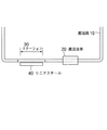
図1は、本発明によるリニアモータ搬送装置が適用される搬送システムを示す。本搬送システムは、搬送路10、この搬送路10を走行する搬送台車20を有し、搬送路10には搬送台車20の停止領域としてステーション30が設定される。ステーション30には、搬送台車20の位置検出のために、被計測手段としてここではリニアスケール40が設置されている。つまり、ステーション30は、搬送台車20の位置決めを必要とする領域であり、ここには搬送台車20に取り付けられた位置検出器(後述する)にて位置を検出可能とするためにリニアスケール40が設置されている。
【0022】
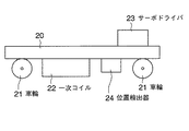
図2を参照して、搬送台車20は、複数(ここでは4つ)の車輪21を持つ台車に、リニア誘導モータを構成するための一次コイル22、サーボドライバ23(励磁制御回路)、前述したリニアスケール40との間で搬送台車20の位置を検出する位置検出器24が搭載されて構成されている。位置検出器24は、周知の磁気式、光学式のいずれでも良く、検出信号をサーボドライバ23に入力する。なお、一次コイル22は、例えば三相交流で駆動するリニア誘導モータの巻き方を有するコイルである。
【0023】
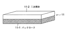
一方、搬送路10は、少なくともその一部、本形態では全域がリニア誘導モータの二次導体(固定子)で構成される。搬送路10に敷設されるリニア誘導モータの二次導体(固定子)の例を図3に示す。
【0024】
図3に示すように、固定子11は、磁性体であるバックヨーク11−1と非磁性体である二次導体11−2とで構成され、それぞれの板材を重ね合わせた構造を持つ。バックヨーク11−1の材料には鉄等の磁性金属や磁性材もしくは合金等が用いられ、二次導体11−2の材料にはアルミ、銅等の非磁性金属や合金等が用いられるがこれらに限定されるものではない。つまり、本発明が適用されるリニア誘導モータの固定子はどのような構造あるいは材料であっても良い。なお、二次導体(固定子)が搬送路10の全域に構成されなくても良いというのは、ステーション30以外の搬送路10の一部に二次導体(固定子)の無い領域があってもその領域では慣性による走行が可能であるからである。
【0025】
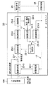
次に、図4を参照して、サーボドライバ23について説明する。サーボドライバ23は、位置検出器24からの検出信号を受け、ステーション30の領域では位置決め停止制御を行う一方、ステーション30以外の搬送路10では速度制御等による非位置決め制御を行うものである。特に、サーボドライバ23は、位置検出器24からの検出信号に基づいて位置決め停止制御を行うと共に、搬送台車20の動作指令を出力する上位制御器100に接続されている。しかも、サーボドライバ23は、位置検出器24からの検出信号により、上位制御器100からの動作指令による非位置決め制御と、位置決め停止制御とを切り替える第1の切替え部23−1を有する。
【0026】
本形態によるサーボドライバ23は、前記動作指令として非位置決め制御における動作指令速度とステーション30の領域での位置決め停止制御における搬送台車20の停止位置指令値とを受け、非位置決め制御においては動作指令速度に基づく速度制御を行い、位置決め停止制御においては停止位置指令値に基づく停止位置に搬送台車を停止させるための制御を行う。
【0027】
詳しく説明すると、サーボドライバ23は、一次コイル22を励磁するための励磁回路23−2を有すると共に、非位置決め制御のための速度制御ループL1を有する。速度制御ループL1は、励磁回路23−2で励磁された電流あるいは電圧を検出するための電流・電圧検出器23−3と、検出された電流あるいは電圧から搬送台車20の速度を推定するための速度推定器23−4と、速度推定器23−4による推定速度と上位制御器100からの動作指令速度とに基づいて励磁演算器23−6を介して励磁回路23−2を制御することで速度制御を行う速度制御器23−5とを含む。励磁演算器23−6は増幅器と同様の機能を持つ。
【0028】
サーボドライバ23は更に、位置決め停止制御のための位置決め停止制御ループL2を有する。位置決め停止制御ループL2は、位置検出器24からの検出信号により搬送台車20の位置を演算するための位置演算器23−7と、演算された位置と停止位置指令値とに基づいて位置制御を行うための位置制御器23−8とを含み、位置制御器23−8の出力が速度制御器23−5に入力されるように構成されてループを形成している。そして、上位制御器100から速度制御器23−5への動作指令速度の入力ラインと位置制御器23−8から速度制御器23−5への入力ラインとが第1の切替え部23−1で切り替えられるように構成されている。第1の切替え部23−1は、位置検出器24からの検出信号がある時には位置制御器23−8から速度制御器23−5への入力ラインを接続し、位置検出器24からの検出信号が無い時には上位制御器100から速度制御器23−5への動作指令速度の入力ラインを接続する。
【0029】
サーボドライバ23は更に、位置検出器24からの位置検出信号により速度演算を行うための速度演算器23−9を有し、速度演算器23−9で演算された速度と速度推定器23−4による推定速度のいずれか一方が第2の切替え部23−10を介して速度制御器23−5に与えられるように構成されている。特に、第2の切替え部23−10は、第1の切替え部23−1と同じタイミングで切り替えられ、非位置決め制御においては速度推定器23−4の出力を、位置決め停止制御においては速度演算器23−9の出力をそれぞれ選択するように切替えを行う。
【0030】
以上のような速度推定器23−4、速度演算器23−9を備えた励磁制御回路はベクトルインバータ制御を実現することができる。
【0031】
サーボドライバ23においては更に、非位置決め制御から位置決め停止制御への切替え時あるいはその逆であって速度演算器23−9の出力値と速度推定器23−4の出力値との差が大きい場合に、この差を徐々に小さくしてゆくスムージング処理を行うためのスムージング処理部23−11が第2の切替え部23−10と速度制御器23−5との間に接続されている。
【0032】
以上のような構成によるサーボドライバ23は、以下のように動作する。
【0033】
ア)サーボドライバ23は、上位制御器100から搬送路10での動作指令速度及びステーション30での停止位置を指示される。
【0034】
イ)サーボドライバ23は、位置検出器24から位置検出信号を受けている時には、位置検出器24からの位置情報を元に位置演算器23−7で位置演算を行い、指示された停止位置との距離を考慮しながら位置制御器23−8にて位置制御を行うべく速度制御器23−5に対して制御信号を出力する。
【0035】
ウ)速度制御器23−5は、位置演算が行われている場合には位置制御器23−8からの制御信号、位置演算が行われていない場合には上位制御器100からの動作指令速度を指令速度とし、スムージング処理部23−11からの現在速度と比較演算する。
【0036】
エ)速度制御器23−5の比較演算結果により励磁演算器23−6、励磁回路23−2を経由して搬送台車20に取り付けられた一次コイル22を励磁する。
【0037】
オ)搬送台車20がステーション30に無い場合(位置検出器24からの検出信号が無い場合)には、励磁回路23−2により励磁された電流あるいは電圧を電流・電圧検出器23−3により検出する。
【0038】
カ)電流・電圧検出器23−3により検出された電流あるいは電圧から速度推定器23−4により搬送台車20の速度を推定する。
【0039】
キ)搬送台車20がステーション30に在る場合(位置検出器24からの検出信号が在る場合)には、位置検出器24からの情報を元に速度演算器23−9で速度演算を行う。
【0040】
ク)スムージング処理部23−11では、搬送台車20がステーション30に在る場合には速度演算器23−9の演算結果、その他の場合には、速度推定器23−4の推定結果を基に以下に述べるスムージング処理を行う。
【0041】
スムージング処理は、第2の切替え部23−10による、演算結果と推定結果の切替え時の不連続を回避するための処理であり、一次コイル22への励磁が急激に変化しないようにするための処理である。
【0042】
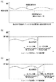
図5を参照して、位置検出器24からの検出信号が無い状態で非位置決め制御による速度制御(センサレス制御)を行う場合、上位制御器100から動作指令速度を受け、電流あるいは電圧から速度推定を行って速度制御を行うが、必ずしも速度推定値と搬送台車20の速度とが一致しているとは限らない(図5a参照)。
【0043】
ここで、位置検出器24からのフィードバックによる制御(センサ付き制御)に切り替えると、速度演算器23−9の出力値と速度推定器23−4の出力値との差が大きい場合には制御切替え点で制御速度が不連続となり搬送台車20に急激な加速度が発生する(図5b参照)。
【0044】
そこで、スムージング処理部23−11は、制御切替え直前の速度推定器23−4の出力値から速度演算器23−9の出力値に徐々に近付けることにより、図5(c)に示すように、搬送台車へ急激な加速度が発生することを防止する。このため、スムージング処理部23−11では、直前の速度制御器23−5への出力値を保持している。
【0045】
なお、図5では、スムージング処理による速度変化は加速度一定(速度変化率一定)としているが、スムージング処理部23−11ではソフトウェアにより処理を行うので、速度の変化率を曲線で与えることも可能である。勿論、速度変化率は差が正であれば正の速度変化率で与えられ、差が負であれば負の速度変化率が与えられる。また、スムージング処理部23−11に、第2の切替え部23−10の切替え機能を持たせるようにしても良い。つまり、スムージング処理部23−11に速度演算器23−9の出力と速度推定器23−4の出力とを入力するようにし、スムージング処理部23−11は位置検出器24からの位置検出信号の有無に応じて速度演算器23−9の出力、速度推定器23−4の出力の一方をスムージング処理したうえで出力する。
【0046】
以上のような構成、作用により、搬送台車20に荷物を載せて運搬し、ステーション30の決められた位置に停止して荷物の移載を行う場合、ステーション30以外の領域では速度制御などの運転形態で搬送台車20をセンサレス制御し、搬送台車20がステーション30の領域に進入すると、制御はセンサ付き制御による位置決め停止制御に切り替わり、搬送台車20は目標位置に停止される。その後、ステーション30をスタートした搬送台車20は、位置検出器24からの位置検出信号が無くなると再びセンサレス制御に切り替えられる。そして、この切替え時点で速度演算器23−9の出力値と速度推定器23−4の出力値との差が大きい場合にも上述したスムージング処理が行われる。
【0047】
位置決め停止制御は、リニアスケール40と位置検出器24によるセンサ付き制御であるので、図6に示すように、高精度での位置決めが行われる。つまり、本発明における位置決め停止制御では、ステーション30の領域に進入すると位置検出器24からの検出信号に基づく連続的な減速制御を行い、停止位置については位置検出器24により搬送台車20の位置を正確に検出して位置制御を行うので、スムーズな減速と正確な停止位置を実現することが可能となる。
【0048】
リニア誘導モータは、装置が簡単で固定子の設置も容易であるので、低コストであることが特徴であり、ステーション30にリニアスケール40を設置すると共に搬送台車20には位置検出器24を設置し、位置検出信号の有無に応じて非位置決め制御と位置決め停止制御とを切り替えるだけで、全体として低コストで高性能なリニアモータ搬送装置が構成できる。しかも、既設のリニア誘導モータを備えた搬送路にステーション30を新設することができる。
【0049】
なお、本発明は、リニア誘導モータを使用し位置決めを必要とするすべてのリニアモータ搬送装置に適用可能である。また、搬送台車20に設置される位置検出器24とステーション30に設置されるリニアスケール40との組み合わせは一例であり、要求される検出精度を満足する他の周知の位置検出手段で実現されても良い。更に、ステーション30以外の搬送路では速度制御に代えて他の制御が行われても良い。この場合、上位制御器100からはその制御形態に応じた指令値が与えられ、速度制御器23−5もその制御形態に応じた制御器に代えられる。
【0050】
【発明の効果】
本発明によれば、以下のような効果が得られる。
【0051】
(1)従来装置、例えば前述した第1の搬送装置であると、二次側固定子として、2種類のものを敷設せねばならない。これに対し、本発明では、固定子はリニア誘導モータの二次導体のみであり、構造が非常に簡単であり、メンテナンスフリーである。
【0052】
(2)既設のリニア誘導モータで構成される、搬送路にステーション部分を追加する場合、搬送台車に位置検出器を設置すると共に、ステーション部にリニアスケール等の被計測手段を設置し、制御装置、つまり励磁制御回路を本発明によるものに交換するだけで良い。
【0053】
(3)本発明による励磁制御回路を用いることにより、ステーション部分でスムーズな加減速制御による高精度での停止位置決めを行うことが可能となる。
【0054】
(4)従来のステーンョン部とそれ以外の搬送路部分では制御方式もしくは制御装置を変える必要があったが、本発明では、励磁制御回路は勿論、制御方式もステーンョン部とそれ以外の搬送路部分で共用される。
【0055】
(5)ステーション部とそれ以外の搬送路で励磁制御回路を共用することにより、ステーション部への進入・脱出時の搬送台車への制御をスムーズに切り替えることが可能となる。
【図面の簡単な説明】
【図1】本発明によるリニアモータ搬送装置が適用される搬送システムを示した図である。
【図2】本発明による搬送台車の構成を概略的に示した図である。
【図3】本発明に使用されるリニア誘導モータの固定子構造の例について示した図である。
【図4】本発明による励磁制御回路の構成を示したブロック図である。
【図5】図4に示したスムージング処理部の作用を説明するための速度特性図である。
【図6】本発明によりステーション部で実行される位置決め停止制御を説明するための速度−位置特性図である。
【符号の説明】
10 搬送路
11 固定子
20 搬送台車
21 車輪
22 一次コイル
23 サーボドライバ(励磁制御回路)
24 位置検出器
30 ステーション
40 リニアスケール
100 上位制御器[0001]
TECHNICAL FIELD OF THE INVENTION
The present invention relates to a linear motor transport device for transporting articles and the like on a predetermined transport path using a linear induction motor.
[0002]
[Prior art]
The following two transfer devices have been proposed as related technologies of this type of linear motor transfer device.
[0003]
In the first transfer device, a secondary stator for a linear reluctance motor is laid in a predetermined section near a transfer station on a transfer path, and a secondary stator for a linear induction motor is installed in a section other than the predetermined section. Is laid. On the other hand, the carrier has a primary-side core having a coil and a general-purpose inverter. Then, a command value to the general-purpose inverter is switched so as to operate as a linear reluctance motor in the predetermined section and to operate as a linear induction motor in a section other than the predetermined section (for example, see Patent Document 1).
[0004]
In the second transfer device, a linear induction motor and a linear step motor are used in combination, and the transfer path other than the station is operated as a linear induction motor, and the station portion is operated as a linear step motor, thereby achieving high-precision stopping. A position determining function and a high-speed transport function are provided (for example, see Patent Document 2).
[0005]
[Patent Document 1]
JP 2001-112119 A (abstract, FIG. 1)
[0006]
[Patent Document 2]
JP-A-59-31216 (page 3, upper left column and upper right column, FIG. 2)
[0007]
[Problems to be solved by the invention]
However, the first transporting device needs to install two types of secondary stators, and the equipment becomes complicated. Further, the cost of the secondary stator of the synchronous type reluctance motor is higher than that of the secondary stator of the linear induction motor. Furthermore, it is not suitable for adding a transfer station to a transport path having an existing linear induction motor.
[0008]
In addition, although the stop positioning accuracy is expected to be improved by improving the thrust at the transfer station, high-precision positioning cannot be performed because a general-purpose inverter is used.
[0009]
On the other hand, in the second transporting apparatus, it is necessary to install a special plate in the station section, so that the equipment becomes complicated as in the first transporting apparatus. Also, two types of excitation circuits are required.
[0010]
Therefore, an object of the present invention is to provide a linear motor transport device capable of positioning and stopping a transport trolley with high accuracy in a stop area set in a transport path.
[0011]
Another object of the present invention is to provide a linear motor transport device in which the laying of the transport path and the configuration of the control device are simple.
[0012]
[Means for Solving the Problems]
According to the present invention, at least a part of the transfer path is formed of a secondary conductor of a linear induction motor, and the transfer carriage on which the primary coil of the linear induction motor and its excitation control circuit are mounted runs on the transfer path, In a linear motor transport device in which a stop area of the transport trolley is set in the transport path, while a measurement target for position detection is installed in the stop area, a position detector is installed in the transport trolley, Wherein the excitation control circuit receives a detection signal from the position detector and performs positioning stop control in the stop area, while performing non-positioning control in a transport path other than the stop area. Is provided.
[0013]
In the present linear motor transport device, the excitation control circuit performs the positioning stop control based on a detection signal from the position detector, and is connected to a higher-level controller that outputs an operation command of the transport vehicle. In addition, there is provided a first switching unit for switching between the non-positioning control and the positioning stop control by an operation command from the higher-level controller according to a detection signal from the position detector.
[0014]
In the present linear motor transfer device, the excitation control circuit receives an operation command speed in the non-positioning control and a stop position command value of the transfer vehicle in the positioning stop control in the stop region as the operation command, In the non-positioning control, speed control based on the operation command speed is performed, and in the positioning stop control, control is performed to stop the carrier at a stop position based on the stop position command value.
[0015]
In the present linear motor transport device, the excitation control circuit further includes an excitation circuit for exciting the primary coil, and a speed control loop for the non-positioning control. A current / voltage detector for detecting the current or voltage excited by the excitation circuit, a speed estimator for estimating the speed of the transport vehicle from the detected current or voltage, and an estimated speed by the speed estimator. A speed controller that performs speed control by controlling the excitation circuit based on the operation command speed from the host controller.
[0016]
In the present linear motor transport device, the excitation control circuit further has a positioning stop control loop for the positioning stop control, and the positioning stop control loop is configured to detect a position of the transport vehicle based on a detection signal from the position detector. And a position controller for performing position control based on the calculated position and the stop position command value, and the output of the position controller is transmitted to the speed controller. It is configured to be input to form a loop, the input line of the operation command speed from the higher-order controller to the speed controller and the input line from the position controller to the speed controller are the It may be configured to be switched by the first switching means.
[0017]
In the present linear motor transport device, the excitation control circuit further includes a speed calculator for performing a speed calculation based on a position detection signal from the position detector, and the speed calculated by the speed calculator and the speed calculated by the speed calculator. The speed estimated by the estimator is provided to the speed controller via a second switching unit that performs switching at the same timing as the first switching unit, and the second switching unit includes the non-switching unit. Switching may be performed so that the output of the speed estimator is selected in the positioning control, and the output of the speed calculator is selected in the positioning stop control.
[0018]
The linear motor transport device further includes a smoothing process for gradually reducing the difference between the output value of the speed estimator and the output value of the speed calculator when switching between the non-positioning control and the positioning stop control. Is preferably connected between the second switching means and the speed controller.
[0019]
In the present linear motor transport device, a linear scale can be used as the position measuring means for position detection.
[0020]
BEST MODE FOR CARRYING OUT THE INVENTION
A preferred embodiment of the linear motor transport device according to the present invention will be described with reference to FIGS.
[0021]
FIG. 1 shows a transfer system to which a linear motor transfer device according to the present invention is applied. The present transport system has a transport path 10 and a transport vehicle 20 traveling on the transport path 10, and a station 30 is set in the transport path 10 as a stop area of the transport vehicle 20. In the station 30, a linear scale 40 is installed as a measurement target in order to detect the position of the transport vehicle 20. That is, the station 30 is an area in which the positioning of the transport vehicle 20 is required, and the linear scale 40 is provided here so that the position can be detected by a position detector (described later) attached to the transport vehicle 20. is set up.
[0022]
Referring to FIG. 2, a transport vehicle 20 is a vehicle having a plurality of (here, four) wheels 21, a primary coil 22 for forming a linear induction motor, a servo driver 23 (excitation control circuit), and the above-described components. A position detector 24 for detecting the position of the carrier 20 with respect to the linear scale 40 is mounted. The position detector 24 may be of a well-known magnetic type or optical type, and inputs a detection signal to the servo driver 23. The primary coil 22 is, for example, a coil having a winding method of a linear induction motor driven by three-phase alternating current.
[0023]
On the other hand, at least a part of the transport path 10, in this embodiment, the entire area is formed of a secondary conductor (stator) of a linear induction motor. FIG. 3 shows an example of the secondary conductor (stator) of the linear induction motor laid on the transport path 10.
[0024]
As shown in FIG. 3, the stator 11 is composed of a back yoke 11-1 which is a magnetic material and a secondary conductor 11-2 which is a non-magnetic material, and has a structure in which respective plate members are overlapped. The back yoke 11-1 is made of a magnetic metal such as iron, a magnetic material or an alloy, and the secondary conductor 11-2 is made of a nonmagnetic metal or an alloy such as aluminum or copper. However, the present invention is not limited to this. That is, the stator of the linear induction motor to which the present invention is applied may have any structure or material. The reason that the secondary conductor (stator) does not have to be formed in the entire area of the transport path 10 is that there is an area without the secondary conductor (stator) in a part of the transport path 10 other than the station 30. This is because traveling by inertia is possible in that region.
[0025]
Next, the servo driver 23 will be described with reference to FIG. The servo driver 23 receives a detection signal from the position detector 24 and performs positioning stop control in the area of the station 30, while performing non-positioning control by speed control or the like in the transport path 10 other than the station 30. In particular, the servo driver 23 performs positioning stop control based on a detection signal from the position detector 24, and is connected to a higher-level controller 100 that outputs an operation command of the carrier 20. In addition, the servo driver 23 has a first switching unit 23-1 that switches between non-positioning control based on an operation command from the host controller 100 and positioning stop control in response to a detection signal from the position detector 24.
[0026]
The servo driver 23 according to the present embodiment receives the operation command speed in the non-positioning control and the stop position command value of the carrier 20 in the positioning stop control in the area of the station 30 as the operation command. Is performed, and in the positioning stop control, control for stopping the transport vehicle at the stop position based on the stop position command value is performed.
[0027]
More specifically, the servo driver 23 has an excitation circuit 23-2 for exciting the primary coil 22, and has a speed control loop L1 for non-positioning control. The speed control loop L1 includes a current / voltage detector 23-3 for detecting the current or voltage excited by the excitation circuit 23-2, and a speed / speed detector 23-3 for estimating the speed of the carrier 20 from the detected current or voltage. By controlling the excitation circuit 23-2 via the excitation calculator 23-6 on the basis of the speed estimated by the speed estimator 23-4 and the speed estimated by the speed estimator 23-4 and the operation command speed from the upper controller 100. A speed controller 23-5 for performing speed control. Excitation calculator 23-6 has the same function as an amplifier.
[0028]
The servo driver 23 further has a positioning stop control loop L2 for positioning stop control. The positioning stop control loop L2 performs position control based on the calculated position and the stop position command value, and a position calculator 23-7 for calculating the position of the carriage 20 based on the detection signal from the position detector 24. And a position controller 23-8 for performing the control, and an output of the position controller 23-8 is configured to be input to the speed controller 23-5 to form a loop. The input line of the operation command speed from the host controller 100 to the speed controller 23-5 and the input line from the position controller 23-8 to the speed controller 23-5 are connected by the first switching unit 23-1. It is configured to be switchable. When there is a detection signal from the position detector 24, the first switching unit 23-1 connects the input line from the position controller 23-8 to the speed controller 23-5, and detects the detection signal from the position detector 24. When there is no, the input line of the operation command speed from the upper controller 100 to the speed controller 23-5 is connected.
[0029]
The servo driver 23 further has a speed calculator 23-9 for performing a speed calculation based on a position detection signal from the position detector 24, and the speed calculated by the speed calculator 23-9 and the speed estimator 23-4. Is provided to the speed controller 23-5 via the second switching unit 23-10. In particular, the second switching unit 23-10 is switched at the same timing as the first switching unit 23-1, and outputs the output of the speed estimator 23-4 in the non-positioning control and the speed calculator in the positioning stop control. Switching is performed so as to select each of the outputs 23-9.
[0030]
The excitation control circuit including the speed estimator 23-4 and the speed calculator 23-9 as described above can realize vector inverter control.
[0031]
In the servo driver 23, further, when switching from the non-positioning control to the positioning stop control or vice versa, when the difference between the output value of the speed calculator 23-9 and the output value of the speed estimator 23-4 is large. A smoothing processing unit 23-11 for performing a smoothing process for gradually reducing this difference is connected between the second switching unit 23-10 and the speed controller 23-5.
[0032]
The servo driver 23 having the above configuration operates as follows.
[0033]
A) The servo driver 23 is instructed by the host controller 100 about the operation command speed on the transport path 10 and the stop position at the station 30.
[0034]
B) When the servo driver 23 receives the position detection signal from the position detector 24, the position calculation unit 23-7 performs the position calculation based on the position information from the position detector 24, and the designated stop position is determined. The control signal is output to the speed controller 23-5 so that the position controller 23-8 controls the position while considering the distance of the position.
[0035]
C) The speed controller 23-5 is a control signal from the position controller 23-8 when the position calculation is performed, and an operation command speed from the upper controller 100 when the position calculation is not performed. Is set as the command speed, and the calculated speed is compared with the current speed from the smoothing processing unit 23-11.
[0036]
D) The primary coil 22 attached to the carrier 20 is excited through the excitation calculator 23-6 and the excitation circuit 23-2 according to the result of the comparison operation of the speed controller 23-5.
[0037]
E) When the carriage 20 is not in the station 30 (when there is no detection signal from the position detector 24), the current or voltage excited by the excitation circuit 23-2 is detected by the current / voltage detector 23-3. I do.
[0038]
F) The speed of the carrier 20 is estimated by the speed estimator 23-4 from the current or voltage detected by the current / voltage detector 23-3.
[0039]
G) When the transport vehicle 20 is at the station 30 (when there is a detection signal from the position detector 24), the speed calculator 23-9 performs speed calculation based on information from the position detector 24. .
[0040]
H) In the smoothing processing unit 23-11, based on the calculation result of the speed calculator 23-9 when the transport carriage 20 is at the station 30, and based on the estimation result of the speed estimator 23-4 in other cases. The following smoothing processing is performed.
[0041]
The smoothing process is a process for avoiding discontinuity at the time of switching between the calculation result and the estimation result by the second switching unit 23-10, and is for preventing the excitation to the primary coil 22 from changing suddenly. Processing.
[0042]
Referring to FIG. 5, when speed control by non-positioning control (sensorless control) is performed in the absence of a detection signal from position detector 24, an operation command speed is received from host controller 100, and speed is estimated from current or voltage. Is performed, the speed control is performed, but the estimated speed value does not always match the speed of the transport vehicle 20 (see FIG. 5A).
[0043]
Here, when the control is switched to the control based on feedback from the position detector 24 (control with a sensor), if the difference between the output value of the speed calculator 23-9 and the output value of the speed estimator 23-4 is large, the control is switched. At this point, the control speed becomes discontinuous, and a sharp acceleration occurs in the transport carriage 20 (see FIG. 5B).
[0044]
Thus, the smoothing processing unit 23-11 gradually approaches the output value of the speed estimator 23-9 from the output value of the speed estimator 23-4 immediately before the control switching, as shown in FIG. This prevents a sudden acceleration from being generated on the transport vehicle. For this reason, the smoothing processing unit 23-11 holds the output value to the speed controller 23-5 immediately before.
[0045]
In FIG. 5, the speed change due to the smoothing process is constant acceleration (constant speed change rate). However, since the smoothing processing unit 23-11 performs processing by software, the speed change rate can be given by a curve. is there. Of course, the speed change rate is given by a positive speed change rate if the difference is positive, and a negative speed change rate is given by a negative difference. Further, the smoothing processing unit 23-11 may have a switching function of the second switching unit 23-10. That is, the output of the speed calculator 23-9 and the output of the speed estimator 23-4 are input to the smoothing processor 23-11, and the smoothing processor 23-11 receives the output of the position detection signal from the position detector 24. One of the output of the speed calculator 23-9 and the output of the speed estimator 23-4 is subjected to smoothing processing before being output depending on the presence or absence.
[0046]
With the above-described configuration and operation, when carrying the luggage on the transport trolley 20 and stopping the luggage at a predetermined position of the station 30 to transfer the luggage, operation such as speed control is performed in an area other than the station 30. When the transport vehicle 20 enters the area of the station 30 by sensorless control in the form, the control is switched to the positioning stop control by the control with the sensor, and the transport vehicle 20 is stopped at the target position. Thereafter, when the position detection signal from the position detector 24 disappears, the transport trolley 20 that has started the station 30 is switched again to the sensorless control. The smoothing process described above is also performed when the difference between the output value of the speed calculator 23-9 and the output value of the speed estimator 23-4 is large at the time of this switching.
[0047]
Since the positioning stop control is control with a sensor by the linear scale 40 and the position detector 24, high-precision positioning is performed as shown in FIG. That is, in the positioning stop control according to the present invention, when the vehicle enters the area of the station 30, continuous deceleration control based on the detection signal from the position detector 24 is performed, and the position of the transport vehicle 20 is determined by the position detector 24 for the stop position. Since the position is controlled by accurately detecting, it is possible to realize a smooth deceleration and an accurate stop position.
[0048]
The linear induction motor is characterized by its low cost because the device is simple and the stator can be easily installed. The linear scale 40 is installed in the station 30 and the position detector 24 is installed in the carrier 20. However, by simply switching between the non-positioning control and the positioning stop control according to the presence or absence of the position detection signal, a low-cost, high-performance linear motor transfer device can be configured as a whole. In addition, the station 30 can be newly provided on the transport path provided with the existing linear induction motor.
[0049]
The present invention is applicable to all linear motor transfer devices that require positioning using a linear induction motor. In addition, the combination of the position detector 24 installed on the transport trolley 20 and the linear scale 40 installed on the station 30 is an example, and is realized by another well-known position detecting means that satisfies the required detection accuracy. Is also good. Further, other control may be performed on the transport path other than the station 30 instead of the speed control. In this case, a command value corresponding to the control mode is given from the host controller 100, and the speed controller 23-5 is also replaced with a controller corresponding to the control mode.
[0050]
【The invention's effect】
According to the present invention, the following effects can be obtained.
[0051]
(1) In the case of the conventional apparatus, for example, the above-described first transport apparatus, two types of secondary-side stators must be laid. On the other hand, in the present invention, the stator is only the secondary conductor of the linear induction motor, and the structure is very simple and maintenance-free.
[0052]
(2) When a station is added to the transport path, which is constituted by an existing linear induction motor, a position detector is installed on the transport trolley, and a measuring unit such as a linear scale is installed in the station, and the control device is installed. That is, it is only necessary to replace the excitation control circuit with the one according to the present invention.
[0053]
(3) By using the excitation control circuit according to the present invention, it is possible to perform stop positioning with high accuracy by smooth acceleration / deceleration control at the station portion.
[0054]
(4) The control method or the control device needs to be changed between the conventional stain portion and the other transport path portion. However, according to the present invention, the control method is not limited to the excitation control circuit but also the stay portion and the other transport path portion. Shared by
[0055]
(5) By sharing the excitation control circuit with the station section and the other transport paths, it is possible to smoothly switch the control to the transport cart when entering and exiting the station section.
[Brief description of the drawings]
FIG. 1 is a diagram showing a transfer system to which a linear motor transfer device according to the present invention is applied.
FIG. 2 is a diagram schematically showing a configuration of a transport vehicle according to the present invention.
FIG. 3 is a diagram showing an example of a stator structure of a linear induction motor used in the present invention.
FIG. 4 is a block diagram showing a configuration of an excitation control circuit according to the present invention.
FIG. 5 is a speed characteristic diagram for explaining the operation of the smoothing processing unit shown in FIG. 4;
FIG. 6 is a speed-position characteristic diagram for explaining positioning stop control executed in the station unit according to the present invention.
[Explanation of symbols]
Reference Signs List 10 transport path 11 stator 20 transport trolley 21 wheels 22 primary coil 23 servo driver (excitation control circuit)
24 Position detector 30 Station 40 Linear scale 100 Host controller