JP2004166323A - Non-contact power feeder - Google Patents
Non-contact power feeder Download PDFInfo
- Publication number
- JP2004166323A JP2004166323A JP2002325971A JP2002325971A JP2004166323A JP 2004166323 A JP2004166323 A JP 2004166323A JP 2002325971 A JP2002325971 A JP 2002325971A JP 2002325971 A JP2002325971 A JP 2002325971A JP 2004166323 A JP2004166323 A JP 2004166323A
- Authority
- JP
- Japan
- Prior art keywords
- power supply
- power
- supply line
- load
- alternating current
- Prior art date
- Legal status (The legal status is an assumption and is not a legal conclusion. Google has not performed a legal analysis and makes no representation as to the accuracy of the status listed.)
- Granted
Links
- 230000007423 decrease Effects 0.000 claims description 25
- 238000001514 detection method Methods 0.000 claims description 9
- 230000001360 synchronised effect Effects 0.000 claims description 6
- 230000020169 heat generation Effects 0.000 abstract description 5
- 239000003990 capacitor Substances 0.000 description 44
- 238000004891 communication Methods 0.000 description 41
- 238000010586 diagram Methods 0.000 description 22
- 230000000694 effects Effects 0.000 description 6
- 238000009499 grossing Methods 0.000 description 5
- 230000002411 adverse Effects 0.000 description 4
- 238000010295 mobile communication Methods 0.000 description 4
- 230000007257 malfunction Effects 0.000 description 3
- 238000000034 method Methods 0.000 description 3
- 230000009467 reduction Effects 0.000 description 3
- 230000004044 response Effects 0.000 description 3
- 230000008859 change Effects 0.000 description 2
- 230000008569 process Effects 0.000 description 2
- 230000000087 stabilizing effect Effects 0.000 description 2
- 230000032258 transport Effects 0.000 description 2
- 230000005540 biological transmission Effects 0.000 description 1
- 238000006243 chemical reaction Methods 0.000 description 1
- 230000003247 decreasing effect Effects 0.000 description 1
- 230000002093 peripheral effect Effects 0.000 description 1
Images
Landscapes
- Current-Collector Devices For Electrically Propelled Vehicles (AREA)
Abstract
Description
【0001】
【発明の属する技術分野】
本発明は、交流電流が流れる給電線に近接して誘導起電力を発生させるピックアップを用いて負荷へ電力を供給する非接触給電装置に関する。
【0002】
【従来の技術】
定められた経路を走行する移動体を用いて荷物を搬送する搬送設備は、工場内又は倉庫内において広く用いられており、移動体に搭載した走行用のモータ又は荷物の積み下ろし装置などの負荷への電力は、前記経路に沿って付設された給電線を介して供給される。電力を供給する装置の一つとして、移動体側に設けたピックアップを給電線から非接触の状態で該給電線に近接させ、該給電線に流れる交流電流により発生する誘導起電力を負荷へ供給する非接触給電装置がある。
【0003】
非接触給電装置を用いて移動体を運用する際には、該移動体が起動する場合または荷物の積み下ろしを行う場合等、単に搬送を行っている場所に比べて大きい電力が必要となる場合がある。移動体が必要とする最大電流を給電線に流し続けたときには、電力の損失が増大するため、移動体が必要とする電力に応じて適切な電流を給電線に流すことが望ましい。
【0004】
そこで、特許文献1には、給電線に交流電流を供給する交流電源にて、交流電流の供給に伴って検出される諸量から移動体の負荷が消費する電力を推定し、推定した電力に基づいて供給する電流量を制御する非接触給電装置が開示されている。また、特許文献2には、移動体が加速、減速または低速運転をしているなどの移動体の移動状況を示す移動状況データを出力する手段を備え、交流電源が供給する電流量を出力された移動状況データに基づいて制御する非接触給電装置が開示されている。更に、特許文献3には、移動体へ与える運転の指示に基づいて移動体が必要とする電力を算出し、算出した電力に応じた電流を供給する非接触給電装置が開示されている。これらの非接触給電装置を用いることにより、適切な電流を給電線に流して非接触給電装置の効率を向上させることができる。
【0005】
【特許文献1】
特開平8−251843号公報
【特許文献2】
特開2001−19120号公報
【特許文献3】
特許第3250534号公報
【0006】
【発明が解決しようとする課題】
従来の非接触給電装置は、大きい電力が必要なときに大きい電流を給電線に流すため、給電線が発熱するという問題があり、給電線での電力の損失が大きくなるという問題がある。また、給電線に流す電流を調整する従来の非接触給電装置は、必要な電力を推定する演算手段が必要となり、構造が複雑になるという問題がある。更に、従来の非接触給電装置は、給電線に流れる電流が大きくなるときには、周囲に発生する電界および磁界が大きくなって、ノイズの混入および誤作動などの悪影響を周囲の機器に及ぼすという問題がある。
【0007】
本発明は、斯かる事情に鑑みてなされたものであって、その目的とするところは、通常用いる給電線に加えて、大きい電力が必要なときに電流を流す給電線を更に備えることにより、給電線での発熱および損失を小さくし、また、演算装置を用いずに供給する電力を制御することで構成を簡単にすることができる非接触給電装置を提供することにある。
【0008】
更に、本発明の他の目的とするところは、複数の給電線に流れる交流電流の位相を互いにずらすことにより、周囲に発生する電界および磁界を小さくすることができる非接触給電装置を提供することにある。
【0009】
【課題を解決するための手段】
第1発明に係る非接触給電装置は、給電線と、該給電線に近接して誘導起電力を発生させるピックアップを用いて負荷へ電力を供給する受電部とを備える非接触給電装置において、第1給電線と、第1給電線へ交流電流を供給する第1電源と、第1給電線に近接する第1ピックアップを有し、負荷へ電力を供給する第1受電部と、第2給電線と、負荷が必要とする電力に応じて第2給電線へ交流電流を供給する第2電源と、第2給電線に近接する第2ピックアップを有し、負荷へ電力を供給する第2受電部とを備えることを特徴とする。
【0010】
第1発明においては、負荷へ電力を供給するための交流電流を流す第1給電線と、大きい電力が必要であるときに交流電流を流す第2給電線とを備えることにより、給電線での発熱および電力の損失を小さくすることができる。
【0011】
第2発明に係る非接触給電装置は、第2給電線を介した電力消費の低下を検出する検出手段と、該検出手段が前記低下を検出した場合に、第2電源に交流電流の供給を停止させる手段とを更に備えることを特徴とする。
【0012】
第2発明においては、負荷が大きい電力を必要としないときに、第2電源から供給される交流電流に係る電流または電圧などの諸量から電力消費の低下を検出し、第2電源からの交流電流の供給を停止することにより、必要な電力を推定する演算装置を用いることなく電力を制御することができる。
【0013】
第3発明に係る非接触給電装置は、負荷が必要とする電力が所定の電力よりも小さい場合に、第2受電部を短絡、又は第2受電部を負荷から切断する手段と、第2給電線を介した電力消費の低下を検出する検出手段と、該検出手段が前記低下を検出した場合に、第2電源に交流電流の供給を停止させる手段とを更に備えることを特徴とする。
【0014】
第3発明においては、負荷が大きい電力を必要としないときに、第2給電線から電力を受電する第2受電部を短絡、又は第2受電部を負荷から切断することによって、第2給電線を介した電力の消費を削減し、更に、第2給電線へ交流電流を供給する第2電源側で電力消費の低下を検出して、第2電源からの交流電流の供給を停止することにより、必要な電力を推定する演算装置を用いることなく電力を制御することができる。
【0015】
第4発明に係る非接触給電装置は、負荷が必要とする電力が所定の電力よりも小さい場合に、負荷が必要とする電力が小さいことを示す情報を送信する手段と、前記情報を受信する受信手段と、該受信手段が前記情報を受信した場合に、第2電源に交流電流の供給を停止させる手段とを更に備えることを特徴とする。
【0016】
第4発明においては、負荷が大きい電力を必要としないときに、必要な電力が小さいことを示す情報を負荷側から第2電源側へ送信し、前記情報に従って第2電源からの交流電流の供給を停止することにより、必要な電力を推定する演算装置を用いることなく電力を制御することができる。
【0017】
第5発明に係る非接触給電装置は、負荷が必要とする電力が所定の電力よりも小さい状態から大きい状態へ変化するときに、電力の供給の指示を送信する手段と、前記指示を受信する供給指示受信手段と、該供給指示受信手段が前記指示を受信した場合に、第2電源に第2給電線へ交流電流を供給させる手段とを更に備えることを特徴とする。
【0018】
第5発明においては、負荷が大きい電力を必要とするときに、電力の供給の指示を負荷側から第2電源側へ送信し、前記指示に従って第2電源が第2給電線へ交流電流を供給することにより、必要な電力を推定する演算装置を用いることなく電力を制御することができる。
【0019】
第6発明に係る非接触給電装置は、第1給電線を介した電力消費の増大を検出する増大検出手段と、該増大検出手段が前記増大を検出した場合に、第2電源に第2給電線へ交流電流を供給させる手段とを更に備えることを特徴とする。
【0020】
第6発明においては、第1給電線に流れる交流電流の消費電力が大きくなったときに、負荷が大きい電力を必要としているとして、第2電源が第2給電線へ交流電流を供給することにより、必要な電力を推定する演算装置を用いることなく電力を制御することができる。
【0021】
第7発明に係る非接触給電装置は、第1電源及び第2電源を含む複数の電源は、互いに略同期し、給電線に流れる交流電流によって発生する磁界が互いに干渉して低減するように、互いの位相を調整した交流電流を供給すべくなしてあることを特徴とする。
【0022】
第7発明においては、複数の電源を同期させ、複数の給電線に流れる交流電流を互いに同じ周波数で互いに位相をずらす等、交流電流によって給電線の周囲に発生する磁界が互いに干渉により低減するように調整する。
【0023】
第8発明に係る非接触給電装置は、第2電源は、第1給電線に近接して誘導起電力を発生させるピックアップを備え、前記ピックアップを介して獲得した電流を第2給電線へ供給すべくなしてあることを特徴とする。
【0024】
第8発明においては、第2電源は、第1給電線に流れる交流電源から電力を得て第2給電線へ交流電流を供給することにより、同期制御を必要とせずに第7発明を実現することができる。
【0025】
【発明の実施の形態】
以下本発明をその実施の形態を示す図面に基づき具体的に説明する。
(実施の形態1)
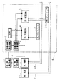
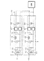
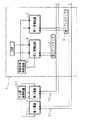
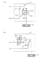
図1は、本発明の非接触給電装置の構成を示すブロック図である。図中6は移動体であり、本発明の非接触給電装置は、移動体6へ電力を供給し、移動体6による荷物の搬送などの作業を制御すべく構成されている。移動体6の移動経路に沿って、交流電流が流れる往路および復路が対になった第1給電線21が備えられており、第1給電線21へ交流電流を常時供給する第1電源が第1給電線21に接続されている。また、同様に交流電流が流れる往路および復路が対になった第2給電線22が、第1給電線21に略平行に備えられており、第2給電線22には、第2給電線22へ交流電流を供給する第2電源12が接続されている。第2電源12には、更に、移動体6を制御するための地上側制御装置51が接続されており、地上側制御装置51は、移動体6が始動するとき等の移動体6が大きい電力を必要とするときに、第2電源12に第2給電線22へ交流電流を供給させるべくなしてある。地上側制御装置51には、更に、無線にて情報を移動体6へ送信する地上側通信装置52が接続されており、地上側制御装置51は、移動体6を制御するための情報を地上側通信装置52を介して移動体6へ送信する。また、地上側制御装置51は、第2電源12から第2給電線22へ供給される交流電流に係る電流値または電圧値などの諸量を測定する機能を備えており、測定した値に対応した電力消費が所定値よりも小さい場合に、第2電源12に交流電流の供給を停止させるべくなしてある。
【0026】
移動体6は、本発明に係る第1受電部を構成する第1ピックアップ31及び第1受電回路3と、本発明に係る第2受電部を構成する第2ピックアップ41及び第2受電回路4とを備えている。第1ピックアップ31は、第1給電線21に非接触で近接しており、第1給電線21に流れる交流電流により誘導起電力を発生させる。第1ピックアップ31は第1受電回路3に接続されており、また、第1受電回路3は移動体6の走行用モータ等の負荷に接続されており、第1受電回路3は、第1ピックアップ31に発生した誘導起電力を整流・安定化して負荷へ電力として供給する。第2ピックアップ41は、第2受電回路4に接続されており、同様に第2給電線22に近接して誘導起電力を発生させる。第2受電回路は、第1受電回路3とは並列に負荷に接続されており、第2ピックアップ41に発生した誘導起電力を負荷へ電力として供給する。第2受電回路4には、移動体6を制御するための移動体側制御装置61が接続されており、移動体側制御装置61には、地上側通信装置52から情報を受信する移動体側通信装置62が接続されている。移動体側通信装置62は、移動体6を制御するための情報を受信して移動体側制御装置61へ入力し、移動体側制御装置61は、移動体6が大きな電力を必要としないときには、第2受電部による受電の停止を指示する受電停止信号を第2受電回路4へ出力する。
【0027】
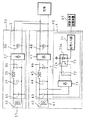
図2は、本発明に係る第1受電部および第2受電部の内部の構成の例を示す回路図であり、図中30は第1受電部、図中40は第2受電部である。第1受電部30は、第1ピックアップ31及び第1受電回路3から構成され、第1ピックアップ31は、図示しないピックアップコアと、該ピックアップコアに巻回されたピックアップコイル32を備えている。第1受電回路3は、ピックアップコイル32に並列に接続された共振コンデンサ33を備えており、ピックアップコイル32及び共振コンデンサ33は、ピックアップコイル32のインダクタンスと共振コンデンサ33のキャパシタンスとが第1給電線21に流れる交流電流の周波数と共振状態になる共振回路をなしている。該共振回路は、ピックアップコイル32に発生した誘導起電力を受けて定電流を出力する。第1受電回路3は、更に、コンデンサ33に並列に接続されたキャパシタ34、インダクタ35及びキャパシタ36をπ型に配置させて備えている。キャパシタ34、インダクタ35及びキャパシタ36は、キャパシタ34及び36のキャパシタンスとインダクタ35のインダクタンスが共振状態になり、前記共振回路からの定電流の出力を定電圧に変換するインピーダンス変換部をなしている。第1受電回路3は、更に、ダイオードを用いた整流部37を備え、整流部37はキャパシタ36に並列に接続されている。整流部37は、前記インピーダンス変換部の出力である定電圧の交流電流を整流する。第1受電回路3は、更に、整流部37に並列に接続された平滑コンデンサ38を備えており、平滑コンデンサ38は、整流部37が出力した電圧を平滑化する。平滑コンデンサ38の出力は、電力として負荷へ供給される。
【0028】
第2受電部40は、第2ピックアップ41及び第2受電回路4から構成され、第2ピックアップ31は、図示しないピックアップコアと、該ピックアップコアに巻回されたピックアップコイル42とを備えており、第2受電回路4は、第1受電回路と同様に、ピックアップコイル42と共振回路をなす共振コンデンサ43と、該共振回路の出力を定電圧に変換するインピーダンス変換部をなすキャパシタ44、インダクタ45及びキャパシタ46と、該インピーダンス変換部の出力を整流する整流部47と、整流部47の出力を平滑化する平滑コンデンサ48とを備えている。
【0029】
第2受電回路4は、更に、第2受電部40による受電を停止させるための停止回路7を備えている。停止回路7は、ダイオードを用いた整流部71を備え、整流部71は、共振コンデンサ43に並列に接続されている。整流部71は、ピックアップコイル42及び共振コンデンサ43からなる共振回路の出力を整流して出力する。停止回路7は、更に、FET72を備え、FET72のドレーン及びソースが整流部71の出力に接続されている。停止回路7は、更に、フォトトランジスタ73a及びLED73bからなるフォトカプラ73を備えており、フォトトランジスタ73aのコレクタがFET72のゲートに接続され、フォトトランジスタ73aのエミッタがFET72のソースに接続されている。停止回路7は、更に、LED73bの入力に接続された信号入力部74を備え、信号入力部74は移動体側制御装置61に接続されている。信号入力部74は、移動体側制御装置61からの受電停止信号の入力を受け付けたときにLED73bへ信号を入力すべくなしてある。
【0030】
移動体側制御装置61から受電停止信号が信号入力部74へ入力されたときには、信号入力部74はLED73bへ信号を入力し、LED73bに電流が流れてフォトカプラ73がオン状態となる。このとき、フォトトランジスタ73aにコレクタ電流が流れ、FET72にゲート電流が流れてFET72がオン状態となる。FET72がオン状態となってドレーン電流が流れるため、整流部71の出力は短絡され、ピックアップコイル42及び共振コンデンサ43からなる共振回路の出力は略0となる。これにより、第2受電部40から負荷へ電力が供給されなくなり、第2受電部40を介した電力の消費が削減される。
【0031】
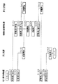
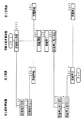
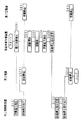
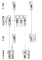
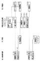
次に、移動体6が停止して小さい電力を消費している状態から、移動体6が移動して大きい電力を消費する状態へ移行し、更に移動体6の移動が終了して小さい電力を消費する状態へ戻る過程を例として、本発明の非接触給電装置の動作を説明する。図3は、実施の形態1に係る本発明の非接触給電装置の動作を説明するタイミングチャートである。第1電源11は第1給電線21へ交流電流を常時供給しており、第1受電部30は、停止している移動体6が必要とする電力を常時供給している。移動体6が移動を開始するときには、地上側制御装置51は、地上側通信装置52を介して移動の指示を移動体6へ送信し(S101)、交流電流の供給の指示を第2電源12へ出力する(S102)。第2電源12は、地上側制御装置51からの指示を受けて、第2給電線22への交流電流の供給を開始する(S201)。移動体側制御装置61は、移動体側通信装置62を介して、地上側制御装置51からの移動指示を受信し(S301)、受電停止信号の出力を中止する(S302)。第2受電部40では、地上側制御装置51からの受電停止信号が中止されたため、フォトカプラ73がオフ状態となり、FET72がオフ状態となって整流部71の出力の短絡が解除される。短絡が解除されたために、第2受電部40は、第2電源12が第2給電線22へ供給する交流電流から、第2給電線22に近接させた第2ピックアップ41を用いて受電を開始する(S401)。
【0032】
受電を開始した第2受電部40から負荷へ電力が供給され、必要な電力を得た移動体6は移動体側制御装置61に制御されて移動を開始し(S303)、必要な作業を行った後で移動を終了する(S304)。移動体側制御装置61は、次に、受電停止信号を第2受電部40へ出力し(S305)、信号入力部74が受電停止信号を受け付けてLED73bへ信号を入力するため、ピックアップコイル42及び共振コンデンサ43からなる共振回路の出力が略0となり、第2受電部は受電を停止する(S402)。第2受電部による受電の停止により、地上側制御装置51は、第2電源12から供給される交流電流の電流値または電圧値に対応する電力消費の低下から、受電の停止を検出し(S103)、第2電源12へ交流電流の供給の停止の指示を出力する(S104)。第2電源12は、交流電流の供給の停止指示を受けて、第2給電線22への交流電流の供給を停止する(S202)。
【0033】
以上詳述した如く、本発明の非接触給電装置は、常時交流電流が流れる第1給電線21と必要時のみに交流電流が流れる第2給電線22とを備え、大きい電力が必要なときに第2給電線22に交流電流を流して電力を供給することにより、一の給電線に大電流を流すことにより大きい電力を供給する従来の非接触給電装置に比べて、夫々の給電線に流れる電流が小さくなるため、給電線での発熱、及び給電線での電力の損失を抑制することができる。また、本発明の非接触給電装置は、大きい電力が必要でないときに第2受電部40を短絡させて第2受電部を用いた電力の消費を略0とし、第2給電線22に流れる交流電流の電力消費が低下したことを検出して前記交流電流の供給を制御することにより、演算装置を用いることなく供給電力の制御が可能となり、非接触給電装置の構成を簡単にすることができる。
【0034】
本実施の形態においては、第1給電線21及び第2給電線22を夫々一対づつ用いる形態を示したが、この形態に限るものではなく、充分な電力を移動体6に供給するために必要な複数の第1給電線21及び第2給電線22を備え、移動体6には夫々の給電線に対応する受電部を備え、複数の第1給電線21及び第2給電線22を用いて電力を供給する形態としてもよい。この場合、受電部は互いに並列に負荷へ接続されておけば良いため、より大きい電力を必要とする移動体6に対して本発明を適用するために給電線および受電部を増設する場合には、増設は容易であり、構造も簡単である。
【0035】
また、本実施の形態においては、ピックアップコイル42及び共振コンデンサ43からなる共振回路の出力を略0とすることで第2受電部40による受電を停止する形態を示したが、第2受電部40から負荷への出力を切断することで電力消費を低下させる形態としてもよい。
【0036】
(実施の形態2)
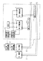
図4は、実施の形態2に係る本発明の非接触給電装置の構成を示すブロック図である。本実施の形態においては、移動体6側から電力の供給の指示を送信することにより、第1給電線21に加えて第2給電線22により移動体6への給電を行う。実施の形態1と同様に、第1電源11、第1給電線21、第2電源12、及び第2給電線22が備えられており、第2電源12には、第2電源12を制御する地上側制御装置51が接続されている。地上側制御装置51には地上側通信装置52が接続されており、地上側制御装置51は、第2電源12を制御するための情報を地上側通信装置52を介して移動体6から受信する。移動体6は、実施の形態1と同様に第1ピックアップ31及び第1受電回路3を備え、更に、本発明に係る第2受電部を構成する第2ピックアップ41及び第2受電回路4とを備えている。第1受電回路3及び第2受電回路4は互いに並列に移動体6の負荷へ接続されている。移動体6は、移動体6を制御するための移動体側制御装置61を備えており、移動体側制御装置61には、無線にて情報を地上側通信装置52へ送信する移動体側通信装置62が接続されている。
【0037】
図5は、実施の形態2における本発明に係る第1受電部および第2受電部の内部の構成の例を示す回路図である。第1受電部30は、第1ピックアップ31及び第1受電回路3から構成され、第1受電部30の構成および機能は、実施の形態1と同様であり、対応する部分に同符号を付してその説明を省略する。第2受電部40は、第2ピックアップ41及び第2受電回路4から構成され、第2受電回路4は、実施の形態1から停止回路を省いた構成となっている。第2受電部40の構成および機能は、停止回路を省いた実施の形態1と同様であり、対応する部分に同符号を付してその説明を省略する。
【0038】
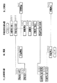
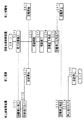
次に、実施例1と同様の例を用いて、本実施の形態に係る本発明の非接触給電装置の動作を説明する。図6は、実施の形態2に係る本発明の非接触給電装置の動作を説明するタイミングチャートである。移動体6が移動を開始するときには、移動体側制御装置61は、第2給電線22への交流電流の供給の指示を、移動体側通信装置62を介して地上側通信装置52へ送信する(S311)。地上側制御装置51は、地上側通信装置52を介して、移動体側制御装置61からの供給指示を受信し(S111)、交流電流の供給の指示を第2電源12へ出力する(S112)。第2電源12は、地上側制御装置51からの指示を受けて、第2給電線22への交流電流の供給を開始する(S211)。第2受電部40は、第2給電線22に流れ始めた交流電流から受電を開始する(S411)。
【0039】
受電を開始した第2受電部40から負荷へ電力が供給され、必要な電力を得た移動体6は移動体側制御装置61に制御されて移動を開始し(S312)、必要な作業を行った後で移動を終了する(S313)。移動体側制御装置61は、次に、交流電流の供給停止の指示を、移動体側通信装置62を介して地上側通信装置52へ送信する(S314)。地上側制御装置51は、地上側通信装置52を介して、移動体側制御装置61からの供給停止指示を受信し(S113)、交流電流の供給停止の指示を第2電源12へ出力する(S114)。第2電源12は、地上側制御装置51からの指示を受けて、第2給電線22への交流電流の供給を停止する(S212)。第2給電線22に交流電流が流れなくなるため、第2受電部40は受電を停止する(S412)。
【0040】
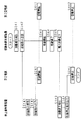
以上の処理では、負荷へ電力を供給しようとして移動体側制御装置61が電力の供給の指示を送信する処理を用いたが、移動体6が移動を開始するときに負荷が消費電力を増大させ、移動体側制御装置61が消費電力の増大を検知して電力の供給の指示を送信する処理を用いても良い。図7は、実施の形態2に係る非接触給電装置が行う動作の第2の例を説明するタイミングチャートである。移動体6が移動を開始するときに、負荷は消費電力を増大させ、移動体側制御装置61は、負荷での消費電力の増大を検出し(S321)、第2給電線22への交流電流の供給の指示を、移動体側通信装置62を介して地上側通信装置52へ送信する(S322)。地上側制御装置51は、地上側通信装置52を介して、移動体側制御装置61からの供給指示を受信し(S121)、交流電流の供給の指示を第2電源12へ出力する(S122)。第2電源12は、地上側制御装置51からの指示を受けて、第2給電線22への交流電流の供給を開始する(S221)。第2受電部40は、第2給電線22に流れ始めた交流電流から受電を開始する(S421)。受電を開始した第2受電部40から負荷へ電力が供給され、必要な電力を得た移動体6は移動体側制御装置61に制御されて移動を開始し(S323)、必要な作業を行った後で移動を終了する(S324)。移動を終了することにより、負荷は消費電力を低下させ、移動体側制御装置61は、負荷での消費電力の低下を検出し(S325)、第2給電線22への交流電流の供給停止の指示を、移動体側通信装置62を介して地上側通信装置52へ送信する(S326)。地上側制御装置51は、地上側通信装置52を介して、移動体側制御装置61からの供給停止指示を受信し(S123)、交流電流の供給停止の指示を第2電源12へ出力する(S124)。第2電源12は、地上側制御装置51からの指示を受けて、第2給電線22への交流電流の供給を停止する(S222)。第2給電線22に交流電流が流れなくなるため、第2受電部40は受電を停止する(S422)。
【0041】
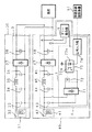
また、負荷が消費する電力の増加を地上側で検出する構成としてもよい。図8は、実施の形態2に係る本発明の非接触給電装置の第2の構成を示すブロック図である。本構成では、地上側制御装置51は、第1電源11に接続されており、第1電源11から第1給電線21へ供給される交流電流に係る電流値または電圧値などの諸量を測定する機能を備えており、測定した値に対応した電力消費が所定値よりも大きい場合、又は電力消費の増大方向への変化が所定よりも大きい場合に、第2電源12に第2給電線22へ交流電流を供給させるべくなしてある。
【0042】
図9は、実施の形態2に係る非接触給電装置が行う動作の第3の例を説明するタイミングチャートである。移動体6が移動を開始するときには、移動体側制御装置61は、移動体6を移動させるべく負荷での電力の消費を増大させる(S331)。負荷での電力消費の増大により、第1給電線21に流れる交流電流から第1受電部30を介して供給される電力の消費が増大し、地上側制御装置51は、第1電源11から供給される交流電流の電流値または電圧値に対応する電力消費の増大を検出し(S131)、交流電流の供給の指示を第2電源12へ出力する(S132)。第2電源12は、地上側制御装置51からの指示を受けて、第2給電線22への交流電流の供給を開始する(S231)。第2受電部40は、第2給電線22に流れ始めた交流電流から受電を開始する(S431)。受電を開始した第2受電部40から負荷へ電力が供給され、必要な電力を得た移動体6は移動体側制御装置61に制御されて移動を開始し(S332)、必要な作業を行った後で移動を終了する(S333)。移動を終了することにより、負荷は電力の消費を低下させ、移動体側制御装置61は、負荷での電力消費の低下を検出し(S334)、第2給電線22への交流電流の供給停止の指示を、移動体側通信装置62を介して地上側通信装置52へ送信する(S335)。地上側制御装置51は、地上側通信装置52を介して、移動体側制御装置61からの供給停止指示を受信し(S133)、交流電流の供給停止の指示を第2電源12へ出力する(S134)。第2電源12は、地上側制御装置51からの指示を受けて、第2給電線22への交流電流の供給を停止する(S232)。第2給電線22に交流電流が流れなくなるため、第2受電部40は受電を停止する(S432)。
【0043】
また、負荷が消費する電力の低下を地上側で検出する構成としてもよい。図10は、実施の形態2に係る本発明の非接触給電装置の第3の構成を示すブロック図である。本構成では、地上側制御装置51は、第2電源12に接続されており、第2電源12から第2給電線22へ供給される交流電流に係る電流値または電圧値などの諸量を測定する機能を備えており、測定した値に対応した電力消費が所定値よりも小さい場合に、第2電源12に第2給電線22への交流電流の供給を停止させるべくなしてある。
【0044】
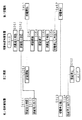
図11は、実施の形態2に係る非接触給電装置が行う動作の第4の例を説明するタイミングチャートである。移動体6が移動を開始するときに、負荷は消費電力を増大させ、移動体側制御装置61は、負荷での消費電力の増大を検出し(S341)、第2給電線22への交流電流の供給の指示を、移動体側通信装置62を介して地上側通信装置52へ送信する(S342)。地上側制御装置51は、地上側通信装置52を介して、移動体側制御装置61からの供給指示を受信し(S141)、交流電流の供給の指示を第2電源12へ出力する(S142)。第2電源12は、地上側制御装置51からの指示を受けて、第2給電線22への交流電流の供給を開始する(S241)。第2受電部40は、第2給電線22に流れ始めた交流電流から受電を開始する(S441)。受電を開始した第2受電部40から負荷へ電力が供給され、必要な電力を得た移動体6は移動体側制御装置61に制御されて移動を開始し(S343)、必要な作業を行った後で移動を終了する(S344)。移動を終了することにより、移動体側制御装置61は、負荷での電力の消費を低下させる(S345)。負荷での電力消費の低下により、第2給電線22に流れる交流電流から第2受電部40を介して供給される電力の消費が低下し、地上側制御装置51は、第2電源12から供給される交流電流の電流値または電圧値に対応する電力消費の低下を検出し(S143)、第2電源12へ交流電流の供給の停止の指示を出力する(S144)。第2電源12は、交流電流の供給の停止指示を受けて、第2給電線22への交流電流の供給を停止する(S242)。第2給電線22に交流電流が流れなくなるため、第2受電部40は受電を停止する(S442)。
【0045】
本実施の形態においては、第2給電線22への交流電流の給電の開始および/又は停止の指示を通信装置を用いて送受信することにより、演算装置を用いることなく供給電力の制御が可能となり、非接触給電装置の構成を簡単にすることができる。なお、本実施の形態においては、無線を用いて通信を行う形態を示しているが、これに限るものではなく、給電線に近接させた通信用のコイルを用いて、給電に用いる交流電流とは別の周波数を有する信号を給電線に流して通信を行うなど、他の方法を用いて通信を行う形態としてもよい。
【0046】
(実施の形態3)
実施の形態3においては、移動体6側から電力の供給の指示を送信することにより、第2受電部40での受電を開始し、停止回路を用いて第2受電部40での受電を停止する。実施の形態3に係る非接触給電装置の構成は、図10に示した実施の形態2の第3の構成と同様であり、その説明を省略する。また、実施の形態3における第1受電部30および第2受電部40の内部の構成は、第2受電部40が停止回路7を備えた図2に示した実施の形態1の構成と同様であり、その説明を省略する。
【0047】
次に、実施例1と同様の例を用いて、本実施の形態に係る本発明の非接触給電装置の動作を説明する。図12は、実施の形態3に係る非接触給電装置が行う動作を説明するタイミングチャートである。移動体6が移動を開始するときに、負荷は消費電力を増大させ、移動体側制御装置61は、負荷での消費電力の増大を検出し(S351)、第2給電線22への交流電流の供給の指示を、移動体側通信装置62を介して地上側通信装置52へ送信する(S352)。地上側制御装置51は、地上側通信装置52を介して、移動体側制御装置61からの供給指示を受信し(S151)、交流電流の供給の指示を第2電源12へ出力する(S152)。第2電源12は、地上側制御装置51からの指示を受けて、第2給電線22への交流電流の供給を開始する(S251)。第2受電部40は、第2給電線22に流れ始めた交流電流から受電を開始する(S451)。受電を開始した第2受電部40から負荷へ電力が供給され、必要な電力を得た移動体6は移動体側制御装置61に制御されて移動を開始し(S353)、必要な作業を行った後で移動を終了する(S354)。移動を終了することにより、負荷は消費電力を低下させ、移動体側制御装置61は、負荷での消費電力の低下を検出し(S355)、受電停止信号を第2受電部40へ出力する(S356)。第2受電部40は、信号入力部74が受電停止信号を受け付けて停止回路7が作動し、ピックアップコイル42及び共振コンデンサ43からなる共振回路の出力が略0となり、受電を停止する(S452)。第2受電部による受電の停止により、地上側制御装置51は、第2電源12から供給される交流電流の電流値または電圧値に対応する電力消費の低下から、受電の停止を検出し(S153)、第2電源12へ交流電流の供給の停止の指示を出力する(S154)。第2電源12は、交流電流の供給の停止指示を受けて、第2給電線22への交流電流の供給を停止する(S252)。
【0048】
本実施の形態においては、第2給電線22への交流電流の給電の開始の指示を通信装置を用いて送受信し、また、大きい電力が必要でないときに第2受電部40を用いた電力の消費を略0として第2給電線22に流れる交流電流の電力消費が低下したことを検出することにより、演算装置を用いることなく供給電力の制御が可能となり、非接触給電装置の構成を簡単にすることができる。
【0049】
(実施の形態4)
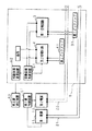
図13は、実施の形態4に係る本発明の非接触給電装置の構成を示すブロック図である。本実施の形態においては、通信装置を用いることなく給電の制御を行う。第1電源11、第1給電線21、第2電源12、及び第2給電線22が備えられており、第1電源11及び第2電源12には、第2電源12を制御する地上側制御装置51が接続されている。地上側制御装置51は、第1電源11から第1給電線21へ供給される交流電流に係る電流値または電圧値などの諸量を測定する機能を備え、測定した値に対応した電力消費が所定値よりも大きい場合、又は電力消費の増大方向への変化が所定よりも大きい場合に、第2電源12に第2給電線22へ交流電流を供給させるべくなしてあり、更に、第2電源12から第2給電線22へ供給される交流電流に係る諸量を測定する機能とを備え、測定した値に対応した電力消費が所定値よりも小さい場合に、第2電源に交流電流の供給を停止させるべくなしてある。移動体6は、実施の形態1と同様に、本発明に係る第1受電部を構成する第1ピックアップ31及び第1受電回路3と、本発明に係る第2受電部を構成する第2ピックアップ41及び第2受電回路4とを備えており、第1受電回路3及び第2受電回路4は互いに並列に移動体6の負荷へ接続されている。第1受電部30および第2受電部40の内部の構成は、図5に示した実施の形態2と同様の構成であり、その説明を省略する。
【0050】
次に、実施例1と同様の例を用いて、本実施の形態に係る非接触給電装置の動作を説明する。図14は、実施の形態4に係る本発明の非接触給電装置の動作を説明するタイミングチャートである。移動体6が移動を開始するときには、移動体側制御装置61は、移動体6を移動させるべく負荷での電力の消費を増大させる(S361)。負荷での電力消費の増大により、第1給電線21に流れる交流電流から第1受電部30を介して供給される電力の消費が増大し、地上側制御装置51は、第1電源11から供給される交流電流の電流値または電圧値に対応する電力消費の増大を検出し(S161)、交流電流の供給の指示を第2電源12へ出力する(S162)。第2電源12は、地上側制御装置51からの指示を受けて、第2給電線22への交流電流の供給を開始する(S261)。第2受電部40は、第2給電線22に流れ始めた交流電流から受電を開始する(S461)。受電を開始した第2受電部40から負荷へ電力が供給され、必要な電力を得た移動体6は移動体側制御装置61に制御されて移動を開始し(S362)、必要な作業を行った後で移動を終了する(S363)。移動を終了することにより、移動体側制御装置61は、負荷での電力の消費を低下させる(S364)。負荷での電力消費の低下により、第2給電線22に流れる交流電流から第2受電部40を介して供給される電力の消費が低下し、地上側制御装置51は、第2電源12から供給される交流電流の電流値または電圧値に対応する電力消費の低下を検出し(S163)、第2電源12へ交流電流の供給の停止の指示を出力する(S164)。第2電源12は、交流電流の供給の停止指示を受けて、第2給電線22への交流電流の供給を停止する(S262)。第2給電線22に交流電流が流れなくなるため、第2受電部40は受電を停止する(S462)。
【0051】
本実施の形態においても、演算装置を用いることなく供給電力の制御が可能となり、また、通信装置を用いずに制御を行うことにより、非接触給電装置の構成をより簡単にすることができる。
【0052】
(実施の形態5)
実施の形態5においては、第2受電部40に停止回路を備えて第2受電部での受電を調整することにより、通信装置を用いることなく給電の制御を行う。実施の形態5に係る非接触給電装置の構成は、図13に示した実施の形態4における構成と同様であり、その説明を省略する。また、実施の形態5における第1受電部30および第2受電部40の内部の構成は、第2受電部40が停止回路7を備えた図2に示した実施の形態1の構成と同様であり、その説明を省略する。
【0053】
次に、実施例1と同様の例を用いて、本実施の形態に係る非接触給電装置の動作を説明する。図15は、実施の形態5に係る本発明の非接触給電装置の動作を説明するタイミングチャートである。移動体6が移動を開始するときには、移動体側制御装置61は、移動体6を移動させるべく負荷での電力の消費を増大させる(S371)。負荷での電力消費の増大により、第1給電線21に流れる交流電流から第1受電部30を介して供給される電力の消費が増大し、地上側制御装置51は、第1電源11から供給される交流電流の電流値または電圧値に対応する電力消費の増大を検出し(S171)、交流電流の供給の指示を第2電源12へ出力する(S172)。第2電源12は、地上側制御装置51からの指示を受けて、第2給電線22への交流電流の供給を開始する(S271)。第2受電部40は、第2給電線22に流れ始めた交流電流から受電を開始する(S471)。受電を開始した第2受電部40から負荷へ電力が供給され、必要な電力を得た移動体6は移動体側制御装置61に制御されて移動を開始し(S372)、必要な作業を行った後で移動を終了する(S373)。移動を終了することにより、負荷は消費電力を低下させ、移動体側制御装置61は、負荷での消費電力の低下を検出し(S374)、受電停止信号を第2受電部40へ出力する(S375)。第2受電部40は、信号入力部74が受電停止信号を受け付けて停止回路7が作動し、ピックアップコイル42及び共振コンデンサ43からなる共振回路の出力が略0となり、受電を停止する(S472)。第2受電部による受電の停止により、地上側制御装置51は、第2電源12から供給される交流電流の電流値または電圧値に対応する電力消費の低下から、受電の停止を検出し(S173)、第2電源12へ交流電流の供給の停止の指示を出力する(S174)。第2電源12は、交流電流の供給の停止指示を受けて、第2給電線22への交流電流の供給を停止する(S272)。移動体側制御装置61からの受電停止信号の出力は、所定時間後に停止され、第2受電部40は、受電可能な状態へと戻る。
【0054】
本実施の形態においても、演算装置を用いることなく供給電力の制御が可能となり、また、通信装置を用いずに制御を行うことにより、非接触給電装置の構成をより簡単にすることができる。
【0055】
(実施の形態6)
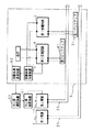
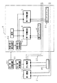
実施の形態6においては、大きい電力が必要なときにダミーの負荷を増設して一時的に電力の消費をより増大させ、負荷での電力消費の増大を地上側制御装置51にてより確実に検出させる。実施の形態6に係る非接触給電装置の構成は、図13に示した実施の形態4における構成と同様であり、その説明を省略する。図16は、実施の形態6における第1受電部30および第2受電部40の内部の構成の例を示す回路図である。第1受電部30の構成は実施の形態1と同様であり、対応する部分に同符号を付してその説明を省略する。第1受電部30と並列に負荷に接続されている第2受電部40は、負荷に接続されている端子A及び端子B間に、負荷と並列にダミー負荷部9が接続されている。また、移動体側制御装置61が接続されている信号入力部74が、ダミー負荷部9に接続されている。また、移動体側制御装置61は、信号入力部74に対してダミー負荷発生信号を入力する機能を有している。第2受電部40のその他の構成は実施の形態1と同様であり、対応する部分に同符号を付してその説明を省略する。
【0056】
図17は、ダミー負荷部9の内部の構成の例を示す回路図である。ダミーの負荷として抵抗を用いた場合の例を図17(a)に示し、ダミーの負荷としてコンデンサを用いた場合の例を図17(b)に示している。負荷として抵抗を用いた場合の例では、ダミー負荷部9は、端子A及び端子B間に抵抗器91とトランジスタ92とを備え、抵抗器91の両端は、端子Aとトランジスタ92のコレクタとに接続され、トランジスタ92のエミッタは端子Bに接続されている。また、ダミー負荷部は、フォトトランジスタ94a及びLED94bからなるフォトカプラ94と抵抗器93とを備えており、抵抗器93の両端は端子Aとフォトトランジスタ94aのコレクタに接続され、フォトトランジスタ94aのエミッタはトランジスタ92のベースに接続されており、更に、LED94bの入力には信号入力部74が接続されている。信号入力部74は、移動体側制御装置61からのダミー負荷発生信号の入力を受け付けたときにLED94bへ信号を入力すべくなしてある。移動体側制御装置61からダミー負荷発生信号が信号入力部74へ入力されたときには、信号入力部74はLED94bへ信号を入力し、LED94bに電流が流れてフォトカプラ94がオン状態となる。このとき、フォトトランジスタ94aにエミッタ電流が流れ、トランジスタ92にベース電流が流れてトランジスタ92がオン状態となる。これによって抵抗器91に電流が流れ、端子A及び端子B間に負荷が発生する。
【0057】
また、負荷としてコンデンサを用いた場合の例では、ダミー負荷部9は、フォトトランジスタ95a及びLED95bからなるフォトカプラ95と抵抗器96とコンデンサ97と抵抗器98とを備えている。コンデンサ97及び抵抗器98は互いに並列に接続され、コンデンサ97及び抵抗器98の一端は端子Bに接続され、コンデンサ97及び抵抗器98の他端は抵抗器96の一端に接続されている。抵抗器96の他端はフォトトランジスタ95aのエミッタに接続されており、フォトトランジスタ95aのコレクタは端子Aに接続されている。また、LED95bの入力には信号入力部74が接続されている。移動体側制御装置61からダミー負荷発生信号が信号入力部74へ入力されたときには、信号入力部74はLED95bへ信号を入力し、LED95bに電流が流れてフォトカプラ95がオン状態となる。このとき、フォトトランジスタ95aにエミッタ電流が流れ、抵抗器96及び抵抗器98に電流が流れてコンデンサ97の両端に電圧が印加され、端子A及び端子B間に負荷が発生する。
【0058】
次に、実施例1と同様の例を用いて、本発明の非接触給電装置の動作を説明する。図18は、実施の形態6に係る本発明の非接触給電装置の動作を説明するタイミングチャートである。移動体6が移動を開始するときには、移動体側制御装置61は、第2受電部40への受電停止信号の出力の中止と、ダミー負荷発生信号の第2受電部40への出力を行う(S381)。第2受電部40の信号入力部74は、LED73bへの信号の入力を停止して第2受電部40を受電可能の状態とすると共に、ダミー負荷部9へ信号を入力し、ダミー負荷部9をオン状態にする(S481)。ダミー負荷部9がオン状態となって端子A及び端子B間にダミー負荷が発生し、負荷に並列に接続されているダミー負荷によって、第1給電線21に流れる交流電流から第1受電部30を介して供給される電力の消費が増大する(S382)。地上側制御装置51は、第1電源11から供給される交流電流の電流値または電圧値に対応する電力消費の増大を検出し(S181)、交流電流の供給の指示を第2電源12へ出力する(S182)。第2電源12は、地上側制御装置51からの指示を受けて、第2給電線22への交流電流の供給を開始する(S281)。第2受電部40は、第2給電線22に流れ始めた交流電流から受電を開始する(S482)。移動体側制御装置61からのダミー負荷発生信号の出力は、所定時間後に停止され、ダミー負荷部9はオフ状態となってダミー負荷は消滅する。受電を開始した第2受電部から負荷へ電力が供給され、必要な電力を得た移動体6は移動体側制御装置61に制御されて移動を開始し(S383)、必要な作業を行った後で移動を終了する(S384)。移動体側制御装置61は、次に、受電停止信号を第2受電回路4へ出力し(S385)、第2受電部は受電を停止する(S483)。第2受電部による受電の停止により、地上側制御装置51は、第2電源12から供給される交流電流の電流値または電圧値に対応する電力消費の低下から受電の停止を検出し(S183)、第2電源12へ交流電流の供給の停止の指示を出力する(S184)。第2電源12は、交流電流の供給の停止指示を受けて、第2給電線22への交流電流の供給を停止する(S282)。
【0059】
本実施の形態においても、演算装置を用いることなく供給電力の制御が可能となり、また、通信装置を用いずに制御を行うことにより、非接触給電装置の構成をより簡単にすることができる。特に、電力の消費が大きくなるときはダミー負荷部9を用いて消費電力を増大し、電力の消費が小さくなるときは停止回路7を用いて第2受電部40での受電を停止することにより、電力の供給の制御を確実に行うことができる。
【0060】
(実施の形態7)
図19は、実施の形態7に係る本発明の非接触給電装置の構成を示すブロック図である。本実施の形態においては、各電源を同期させ、各給電線に流れる交流電流によって発生する磁界が互いにうち消されるように、各給電線に流れる交流電流の位相を互いにずらして、外部への影響を抑制する。実施の形態1と同様に、第1電源11、第1給電線21、第2電源12、及び第2給電線22が備えられており、第2電源12には、第2電源12を制御する地上側制御装置51が接続されている。地上側制御装置51には、実施の形態1と同様に、無線にて情報を移動体6へ送信する地上側通信装置52が接続されている。更に、第2電源12は、第1給電線21に近接しているピックアップ80を備えている。ピックアップ80は、常時交流電流が流れる第1給電線21から誘導起電力を得て第2電源12へ供給する。移動体6の構成は実施の形態1と同様であり、対応する部分に同符号を付してその説明を省略する。
【0061】
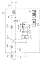
図20は、実施の形態7に係る第2電源12の内部の構成の例を示した回路図である。ピックアップ80は、図示しないピックアップコアと、該ピックアップコアに巻回されたピックアップコイル801を備えている。ピックアップコイル801はインダクタ802に接続され、インダクタ802はコンデンサ804に、コンデンサ804はコンデンサ803に夫々直列に接続され、コンデンサ803は更にピックアップコイル801に接続されて、ピックアップコイル801、インダクタ802、コンデンサ804及びコンデンサ803がループ状に接続された直列回路をなしている。該直列回路は、ピックアップコイル801、インダクタ802、コンデンサ804及びコンデンサ803の特性定数が第1給電線21に流れる交流電流の周波数と共振状態になる共振回路をなしている。コンデンサ804は、インダクタ805及びトランス806が直列に接続された回路に並列に接続されており、トランス806は第2給電線22に接続されている。前記共振回路は、ピックアップコイル801に発生した誘導起電力を受けてコンデンサ804の両端から電力を出力し、インダクタ805及びトランス806は、位相および電圧を適切な値に変換して、第1給電線21に流れる交流電流とは逆位相の交流電流を第2給電線22へ供給すべくなしてある。
【0062】
コンデンサ804には、ダイオードを用いた整流部807が並列に接続しており、整流部71は、前記共振回路の出力を整流して出力する。整流部71の出力には、FET808のドレーン及びソースが接続されている。更に、フォトトランジスタ809a及びLED809bからなるフォトカプラ809が備えられており、フォトトランジスタ809aのコレクタがFET808のゲートに接続され、フォトトランジスタ809aのエミッタがFET808のソースに接続されている。LED809bの入力には、信号を出力する制御器810が接続されており、制御器810には、トランス86へ入力される電流の電流値又は電圧値を測定するセンサ811と地上側制御装置51が接続されている。制御器810は、センサ811で測定された値に対応した消費電力が所定値よりも小さいときにLED804aへ信号を出力し、地上側制御装置51から交流電流の供給の指示を受け付けたときにLED804aへの信号の出力を停止すべくなしてある。
【0063】
移動体6が大きい電力を必要とするときは、地上側制御装置51から制御器810へ交流電流の供給の指示が入力され、制御器810はLED809bへの信号の出力を停止し、フォトカプラ809がオフ状態となってFET808がオフ状態となる。コンデンサ804の両端が短絡されないため、第2電源12は、ピックアップ80を用いて第1給電線21に流れる交流電流から給電し、第1給電線21に流れる交流電流とは逆位相の交流電流を第2給電線22へ供給する。第2受電部は、第2給電線22に流れる交流電流から電力を得て移動体6の負荷へ供給する。
【0064】
移動体6が大きい電力を必要としないときは、実施の形態1と同様に、第2受電部が受電を停止し、制御器810は、センサ811で測定された値から電力消費の低下を検出し、LED804aへ信号を出力する。このとき、LED809bに電流が流れてフォトカプラ809がオン状態となり、FET808がオン状態となって整流部807の出力は短絡され、コンデンサ804の両端が短絡される。ピックアップコイル801、インダクタ802、コンデンサ804及びコンデンサ803からなる共振回路の出力は略0となり、第2電源12は、第2給電線22への交流電流の供給を停止する。
【0065】
本実施の形態においては、複数の給電線に流れる交流電流を、同じ周波数で互いに逆位相で流すため、交流電流によって周囲に発生する電界および磁界が互いに打ち消し合って、ノイズの混入または誤作動などの他の装置に与える悪影響を抑制することができる。また、第2電源12から第2給電線22へ供給すべき交流電流を、第1給電線21に流れる交流電流からピックアップ80を用いて受電することにより、第2電源12は、電流を発生・安定させる機能を必要とせず、更に第1電源12との同期を維持する機能を必要とせずに、第1給電線に流れる交流電流に同期した交流電流を供給することが可能となり、非接触給電装置を小型にすることができる。
【0066】
なお、第1電源11と第2電源とが互いに逆位相の交流電流を供給するのではなく、発生する磁界がよりよくうち消し合って低減されるように互いに交流電流の位相を調整する形態としてもよい。また、第2電源12が第1給電線21に流れる交流電流から受電する構成ではなく、第1電源11および第2電源12を互いに同期させる制御を行い、互いに逆位相の交流電流を供給させる構成としても良い。この場合でも、他の装置に与える悪影響を抑制する非接触給電装置を実現することができる。
【0067】
また、以上の実施の形態1乃至7の全てにおいて、地上側制御装置51は、第1電源11及び第2電源12の外側に構成してある形態を示しているが、地上側制御装置51を第1電源11又は第2電源12と一体に構成した形態としてもよい。
【0068】
【発明の効果】
第1発明においては、常時交流電流を流して負荷へ電力を供給する第1給電線と、負荷が大きい電力を必要とするときに交流電流を流す第2給電線とを備えることにより、一の給電線に大電流を流すことにより大きい電力を供給する従来の非接触給電装置に比べて、夫々の給電線に流れる電流が小さくなるため、給電線での発熱、及び給電線での電力の損失を抑制することができる。
【0069】
第2発明においては、負荷が大きい電力を必要としないときに、第2電源から供給される交流電流に係る電流または電圧などの諸量から電力消費の低下を検出し、第2電源からの交流電流の供給を停止することにより、必要な電力を推定する演算装置を用いることなく供給電力の制御が可能となり、非接触給電装置の構成を簡単にすることができる。
【0070】
第3発明においては、負荷が大きい電力を必要としないときに、第2給電線を介した電力の消費を削減し、第2給電線へ交流電流を供給する第2電源側で電力の消費の削減を検出して、第2電源からの交流電流の供給を停止することにより、必要な電力を推定する演算装置を用いることなく供給電力の制御が可能となり、非接触給電装置の構成を簡単にすることができる。
【0071】
第4発明においては、負荷が大きい電力を必要としないときに、必要な電力が小さいことを示す情報を負荷側から第2電源側へ送信し、前記情報に従って第2電源からの交流電流の供給を停止することにより、必要な電力を推定する演算装置を用いることなく供給電力の制御が可能となり、非接触給電装置の構成を簡単にすることができる。
【0072】
第5発明においては、負荷が大きい電力を必要とするときに、電力の供給の指示を負荷側から第2電源側へ送信し、前記指示に従って第2電源が第2給電線へ交流電流を供給することにより、必要な電力を推定する演算装置を用いることなく供給電力の制御が可能となり、非接触給電装置の構成を簡単にすることができる。
【0073】
第6発明においては、第1給電線に流れる交流電流からの消費電力が大きくなったときに、負荷が大きい電力を必要としているとして、第2電源が第2給電線へ交流電流を供給することにより、必要な電力を推定する演算装置を用いることなく供給電力の制御が可能となり、非接触給電装置の構成を簡単にすることができる。
【0074】
第7発明においては、複数の電源を同期させ、複数の給電線に流れる交流電流を互いに同じ周波数で互いに位相をずらす等、交流電流によって給電線の周囲に発生する磁界が互いに干渉により低減するように調整することにより、電磁波によるノイズの混入または誤作動などの他の装置に与える悪影響を抑制することができる。
【0075】
第8発明においては、第2電源は、第1給電線に流れる交流電源から電力を得て第2給電線へ交流電流を供給することにより、電流を発生・安定させる機能、及び第1電源との同期を維持する機能を必要とせず、非接触給電装置を小型にすることができる等、本発明は優れた効果を奏する。
【図面の簡単な説明】
【図1】本発明の非接触給電装置の構成を示すブロック図である。
【図2】本発明に係る第1受電部および第2受電部の内部の構成の例を示す回路図である。
【図3】実施の形態1に係る本発明の非接触給電装置の動作を説明するタイミングチャートである。
【図4】実施の形態2に係る本発明の非接触給電装置の構成を示すブロック図である。
【図5】実施の形態2における本発明に係る第1受電部および第2受電部の内部の構成の例を示す回路図である。
【図6】実施の形態2に係る本発明の非接触給電装置の動作を説明するタイミングチャートである。
【図7】実施の形態2に係る非接触給電装置が行う動作の第2の例を説明するタイミングチャートである。
【図8】実施の形態2に係る本発明の非接触給電装置の第2の構成を示すブロック図である。
【図9】実施の形態2に係る非接触給電装置が行う動作の第3の例を説明するタイミングチャートである。
【図10】実施の形態2に係る本発明の非接触給電装置の第3の構成を示すブロック図である。
【図11】実施の形態2に係る非接触給電装置が行う動作の第4の例を説明するタイミングチャートである。
【図12】実施の形態3に係る非接触給電装置が行う動作を説明するタイミングチャートである。
【図13】実施の形態4に係る本発明の非接触給電装置の構成を示すブロック図である。
【図14】実施の形態4に係る本発明の非接触給電装置の動作を説明するタイミングチャートである。
【図15】実施の形態5に係る本発明の非接触給電装置の動作を説明するタイミングチャートである。
【図16】実施の形態6における第1受電部および第2受電部の内部の構成の例を示す回路図である。
【図17】ダミー負荷部の内部の構成の例を示す回路図である。
【図18】実施の形態6に係る本発明の非接触給電装置の動作を説明するタイミングチャートである。
【図19】実施の形態7に係る本発明の非接触給電装置の構成を示すブロック図である。
【図20】実施の形態7に係る第2電源の内部の構成の例を示した回路図である。
【符号の説明】
11 第1電源
12 第2電源
21 第1給電線
22 第2給電線
30 第1受電部
31 第1ピックアップ
40 第2受電部
41 第2ピックアップ
51 地上側制御装置
7 停止回路[0001]
TECHNICAL FIELD OF THE INVENTION
The present invention relates to a contactless power supply device that supplies power to a load using a pickup that generates an induced electromotive force in proximity to a power supply line through which an alternating current flows.
[0002]
[Prior art]
Transport equipment that transports luggage using a moving object that travels on a prescribed route is widely used in factories or warehouses, and is used for loads such as a motor for traveling mounted on the moving object or a device for unloading luggage. Is supplied via a power supply line provided along the path. As one of devices for supplying power, a pickup provided on a moving body side is brought close to the power supply line in a non-contact state from the power supply line, and an induced electromotive force generated by an alternating current flowing in the power supply line is supplied to a load. There is a non-contact power supply device.
[0003]
When a mobile unit is operated using a non-contact power supply device, a case where a large amount of power is required compared to a place where the mobile unit is simply transported, such as when the mobile unit is activated or when loading / unloading a load is performed. is there. When the maximum current required by the moving body is continuously supplied to the power supply line, power loss increases. Therefore, it is desirable to supply an appropriate current to the power supply line according to the power required by the moving body.
[0004]
Therefore,
[0005]
[Patent Document 1]
JP-A-8-251843
[Patent Document 2]
JP 2001-19120 A
[Patent Document 3]
Japanese Patent No. 3250534
[0006]
[Problems to be solved by the invention]
The conventional non-contact power supply device has a problem that the power supply line generates heat because a large current flows through the power supply line when a large amount of power is required, and there is a problem that power loss in the power supply line increases. Further, the conventional non-contact power supply device that adjusts the current flowing through the power supply line requires a calculation unit for estimating necessary power, and has a problem that the structure is complicated. Furthermore, the conventional non-contact power supply device has a problem that when the current flowing through the power supply line increases, the electric and magnetic fields generated around the power supply increase, and adverse effects such as noise mixing and malfunctions are exerted on peripheral devices. is there.
[0007]
The present invention has been made in view of the above-described circumstances, and an object thereof is to further include a power supply line through which a current flows when large power is required, in addition to a power supply line that is normally used. It is an object of the present invention to provide a non-contact power supply device capable of reducing heat generation and loss in a power supply line and simplifying a configuration by controlling power supplied without using an arithmetic device.
[0008]
It is a further object of the present invention to provide a non-contact power supply device capable of reducing the electric and magnetic fields generated around it by shifting the phases of alternating currents flowing through a plurality of power supply lines. It is in.
[0009]
[Means for Solving the Problems]
A non-contact power supply device according to a first aspect of the present invention is a non-contact power supply device including: a power supply line; and a power receiving unit that supplies power to a load using a pickup that generates an induced electromotive force in proximity to the power supply line. A first power supply line, a first power supply for supplying an alternating current to the first power supply line, a first power receiving unit that has a first pickup close to the first power supply line and supplies power to a load, and a second power supply line A second power supply for supplying an alternating current to the second power supply line according to the power required by the load; and a second power receiving unit having a second pickup close to the second power supply line and supplying power to the load And characterized in that:
[0010]
In the first invention, by providing a first power supply line through which an alternating current for supplying power to a load flows and a second power supply line through which an alternating current flows when large power is required, the power supply line Heat generation and power loss can be reduced.
[0011]
A contactless power supply device according to a second aspect of the present invention includes a detection unit that detects a decrease in power consumption via a second power supply line, and supplies an AC current to a second power supply when the detection unit detects the decrease. And stopping means.
[0012]
In the second invention, when the load does not require a large amount of power, a decrease in power consumption is detected from various quantities such as a current or a voltage related to an alternating current supplied from the second power supply, and the AC power from the second power supply is detected. By stopping the supply of current, power can be controlled without using an arithmetic unit that estimates required power.
[0013]
The non-contact power supply device according to a third aspect of the present invention includes a means for short-circuiting the second power receiving unit or disconnecting the second power receiving unit from the load when the power required by the load is smaller than the predetermined power; The power supply system further includes detection means for detecting a decrease in power consumption via the electric wire, and means for stopping supply of the alternating current to the second power supply when the detection means detects the decrease.
[0014]
In the third invention, when the load does not require large power, the second power supply line that receives power from the second power supply line is short-circuited, or the second power supply unit is disconnected from the load, so that the second power supply line is provided. By reducing the power consumption through the second power supply, and detecting the decrease in the power consumption on the second power supply side that supplies the AC current to the second power supply line, and stopping the supply of the AC current from the second power supply. In addition, power can be controlled without using an arithmetic unit that estimates required power.
[0015]
A wireless power supply device according to a fourth aspect of the present invention is configured to: when the power required by the load is smaller than the predetermined power, transmit information indicating that the power required by the load is small, and receive the information. It is characterized by further comprising receiving means, and means for stopping supply of an alternating current to the second power supply when the receiving means receives the information.
[0016]
In the fourth invention, when the load does not require large power, information indicating that the required power is small is transmitted from the load side to the second power supply side, and the supply of the alternating current from the second power supply is performed according to the information. , Power can be controlled without using an arithmetic unit that estimates required power.
[0017]
A wireless power supply device according to a fifth aspect of the present invention is configured to transmit a power supply instruction when the power required by the load changes from a state smaller than a predetermined power to a state larger than a predetermined power, and to receive the instruction. It is characterized by further comprising a supply instruction receiving means, and means for causing the second power supply to supply an alternating current to the second power supply line when the supply instruction receiving means receives the instruction.
[0018]
In the fifth invention, when the load requires a large amount of power, a power supply instruction is transmitted from the load side to the second power supply side, and the second power supply supplies an alternating current to the second power supply line according to the instruction. By doing so, power can be controlled without using an arithmetic unit that estimates required power.
[0019]
A contactless power supply device according to a sixth aspect of the present invention includes an increase detection unit that detects an increase in power consumption through the first power supply line, and a second power supply to the second power supply when the increase detection unit detects the increase. Means for supplying an alternating current to the electric wire.
[0020]
In the sixth invention, when the power consumption of the AC current flowing through the first power supply line increases, the second power supply supplies the AC current to the second power supply line by determining that the load requires a large power. In addition, power can be controlled without using an arithmetic unit that estimates required power.
[0021]
The non-contact power supply device according to the seventh invention is such that the plurality of power supplies including the first power supply and the second power supply are substantially synchronized with each other, and the magnetic fields generated by the AC current flowing through the power supply line interfere with each other and are reduced. It is characterized in that alternating currents whose phases are adjusted are supplied.
[0022]
In the seventh invention, a plurality of power sources are synchronized, and alternating currents flowing through the plurality of power supply lines are shifted in phase from each other at the same frequency so that magnetic fields generated around the power supply lines by the AC current are reduced by interference with each other. Adjust to
[0023]
According to an eighth aspect of the present invention, in the non-contact power supply device, the second power supply includes a pickup that generates the induced electromotive force in proximity to the first power supply line, and supplies a current obtained through the pickup to the second power supply line. It is characterized by what it does.
[0024]
In the eighth invention, the second power supply obtains power from an AC power supply flowing through the first power supply line and supplies an AC current to the second power supply line, thereby realizing the seventh invention without requiring synchronous control. be able to.
[0025]
BEST MODE FOR CARRYING OUT THE INVENTION
Hereinafter, the present invention will be specifically described with reference to the drawings showing the embodiments.
(Embodiment 1)
FIG. 1 is a block diagram showing the configuration of the contactless power supply device of the present invention. In the figure,
[0026]
The moving
[0027]
FIG. 2 is a circuit diagram showing an example of an internal configuration of the first power receiving unit and the second power receiving unit according to the present invention. In the drawing,
[0028]
The second
[0029]
The second
[0030]
When a power reception stop signal is input from the moving body
[0031]
Next, the state in which the moving
[0032]
The power is supplied to the load from the second
[0033]
As described in detail above, the non-contact power supply device of the present invention includes the first
[0034]
In the present embodiment, the mode in which each of the first
[0035]
Further, in the present embodiment, the mode in which the power reception by the second
[0036]
(Embodiment 2)
FIG. 4 is a block diagram illustrating a configuration of a wireless power supply device according to a second embodiment of the present invention. In the present embodiment, power is supplied to the
[0037]
FIG. 5 is a circuit diagram showing an example of the internal configuration of the first power receiving unit and the second power receiving unit according to the present invention in the second embodiment. The first
[0038]
Next, the operation of the non-contact power supply device of the present invention according to the present embodiment will be described using an example similar to the first embodiment. FIG. 6 is a timing chart for explaining the operation of the contactless power supply device according to the second embodiment of the present invention. When the moving
[0039]
The power is supplied to the load from the second
[0040]
In the above-described processing, the processing is performed in which the mobile-
[0041]
Further, a configuration may be adopted in which an increase in the power consumed by the load is detected on the ground side. FIG. 8 is a block diagram showing a second configuration of the wireless power supply device according to the second embodiment of the present invention. In this configuration, the ground-
[0042]
FIG. 9 is a timing chart illustrating a third example of the operation performed by the contactless power supply device according to the second embodiment. When the moving
[0043]
Further, a configuration may be adopted in which a decrease in the power consumed by the load is detected on the ground side. FIG. 10 is a block diagram showing a third configuration of the non-contact power feeding device according to the second embodiment of the present invention. In this configuration, the ground-
[0044]
FIG. 11 is a timing chart illustrating a fourth example of the operation performed by the contactless power supply device according to the second embodiment. When the moving
[0045]
In the present embodiment, by transmitting and receiving an instruction to start and / or stop supplying the alternating current to the second
[0046]
(Embodiment 3)
In the third embodiment, power transmission in the second
[0047]
Next, the operation of the non-contact power supply device of the present invention according to the present embodiment will be described using an example similar to the first embodiment. FIG. 12 is a timing chart illustrating an operation performed by the non-contact power supply device according to
[0048]
In the present embodiment, an instruction to start the supply of the alternating current to the second
[0049]
(Embodiment 4)
FIG. 13 is a block diagram illustrating a configuration of a wireless power supply device according to a fourth embodiment of the present invention. In the present embodiment, power supply is controlled without using a communication device. A first power supply 11, a first
[0050]
Next, the operation of the non-contact power supply device according to the present embodiment will be described using an example similar to that of the first embodiment. FIG. 14 is a timing chart illustrating the operation of the contactless power supply device according to the fourth embodiment of the present invention. When the moving
[0051]
Also in the present embodiment, it is possible to control the supplied power without using an arithmetic device, and by performing control without using a communication device, it is possible to further simplify the configuration of the wireless power supply device.
[0052]
(Embodiment 5)
In the fifth embodiment, power supply is controlled without using a communication device by providing a stop circuit in second
[0053]
Next, the operation of the non-contact power supply device according to the present embodiment will be described using an example similar to that of the first embodiment. FIG. 15 is a timing chart illustrating the operation of the non-contact power feeding device according to Embodiment 5 of the present invention. When the moving
[0054]
Also in the present embodiment, it is possible to control the supplied power without using an arithmetic device, and by performing control without using a communication device, it is possible to further simplify the configuration of the wireless power supply device.
[0055]
(Embodiment 6)
In the sixth embodiment, when a large amount of power is required, a dummy load is added to temporarily increase the power consumption, and the increase in the power consumption at the load is more reliably performed by the
[0056]
FIG. 17 is a circuit diagram showing an example of the internal configuration of the
[0057]
In the case where a capacitor is used as a load, the
[0058]
Next, the operation of the non-contact power supply device of the present invention will be described using an example similar to that of the first embodiment. FIG. 18 is a timing chart illustrating the operation of the non-contact power feeding device according to the sixth embodiment of the present invention. When the moving
[0059]
Also in the present embodiment, it is possible to control the supplied power without using an arithmetic device, and by performing control without using a communication device, it is possible to further simplify the configuration of the wireless power supply device. In particular, when the power consumption is large, the power consumption is increased by using the
[0060]
(Embodiment 7)
FIG. 19 is a block diagram illustrating a configuration of a contactless power supply device according to a seventh embodiment of the present invention. In the present embodiment, the phases of the alternating currents flowing through the power supply lines are shifted from each other so that the magnetic fields generated by the AC currents flowing through the power supply lines are canceled out from each other so as to synchronize the power sources, and influence the outside. Suppress. As in the first embodiment, a first power supply 11, a first
[0061]
FIG. 20 is a circuit diagram showing an example of the internal configuration of the
[0062]
A
[0063]
When the moving
[0064]
When the moving
[0065]
In the present embodiment, since alternating currents flowing in a plurality of power supply lines are flowed at the same frequency and in opposite phases, electric and magnetic fields generated by the alternating current cancel each other out, causing noise mixing or malfunction. The adverse effect on other devices can be suppressed. The
[0066]
Note that the first power supply 11 and the second power supply do not supply alternating currents with phases opposite to each other, but adjust the phase of the alternating current with each other so that the generated magnetic field is better canceled out and reduced. Is also good. Also, instead of the configuration in which the
[0067]
Further, in all of the first to seventh embodiments, the ground-
[0068]
【The invention's effect】
In the first invention, by providing a first power supply line that constantly supplies an AC current to supply power to a load, and a second power supply line that supplies an AC current when the load requires a large amount of power, one power supply line is provided. Since the current flowing through each power supply line is smaller than that of a conventional non-contact power supply device that supplies more power when a large current flows through the power supply line, heat generation in the power supply line and power loss in the power supply line Can be suppressed.
[0069]
In the second invention, when the load does not require a large amount of power, a decrease in power consumption is detected from various quantities such as a current or a voltage related to an alternating current supplied from the second power supply, and the AC power from the second power supply is detected. By stopping the current supply, it is possible to control the supplied power without using an arithmetic device for estimating the required power, and the configuration of the wireless power supply device can be simplified.
[0070]
In the third invention, when the load does not require a large amount of power, the power consumption via the second power supply line is reduced, and the power consumption on the second power supply side that supplies an alternating current to the second power supply line is reduced. By detecting the reduction and stopping the supply of the alternating current from the second power supply, it is possible to control the supply power without using an arithmetic unit for estimating the required power, and to simplify the configuration of the contactless power supply device. can do.
[0071]
In the fourth invention, when the load does not require large power, information indicating that the required power is small is transmitted from the load side to the second power supply side, and the supply of the alternating current from the second power supply is performed according to the information. , Power supply can be controlled without using an arithmetic unit for estimating the required power, and the configuration of the contactless power supply device can be simplified.
[0072]
In the fifth invention, when the load requires a large amount of power, a power supply instruction is transmitted from the load side to the second power supply side, and the second power supply supplies an alternating current to the second power supply line according to the instruction. By doing so, it becomes possible to control the supplied power without using an arithmetic unit for estimating the required power, and the configuration of the contactless power supply device can be simplified.
[0073]
In the sixth invention, when the power consumption from the AC current flowing through the first power supply line increases, the second power supply supplies the AC current to the second power supply line on the assumption that the load requires large power. Accordingly, the supplied power can be controlled without using an arithmetic device for estimating the required power, and the configuration of the wireless power supply device can be simplified.
[0074]
In the seventh invention, a plurality of power sources are synchronized, and alternating currents flowing through the plurality of power supply lines are shifted in phase from each other at the same frequency so that magnetic fields generated around the power supply lines by the AC current are reduced by interference with each other. In this case, adverse effects on other devices such as noise mixing or malfunction due to electromagnetic waves can be suppressed.
[0075]
In the eighth invention, the second power supply has a function of generating and stabilizing a current by obtaining power from an AC power supply flowing through the first power supply line and supplying an AC current to the second power supply line. The present invention has an excellent effect, for example, it is not necessary to have a function of maintaining the synchronization, and the size of the wireless power supply device can be reduced.
[Brief description of the drawings]
FIG. 1 is a block diagram illustrating a configuration of a wireless power supply device according to the present invention.
FIG. 2 is a circuit diagram showing an example of an internal configuration of a first power receiving unit and a second power receiving unit according to the present invention.
FIG. 3 is a timing chart illustrating an operation of the wireless power supply device according to the first embodiment of the present invention.
FIG. 4 is a block diagram illustrating a configuration of a wireless power supply device according to a second embodiment of the present invention.
FIG. 5 is a circuit diagram showing an example of an internal configuration of a first power receiving unit and a second power receiving unit according to the present invention in Embodiment 2.
FIG. 6 is a timing chart illustrating the operation of the wireless power supply device according to the second embodiment of the present invention.
FIG. 7 is a timing chart illustrating a second example of the operation performed by the wireless power supply device according to the second embodiment.
FIG. 8 is a block diagram showing a second configuration of the wireless power supply device according to the second embodiment of the present invention.
FIG. 9 is a timing chart illustrating a third example of the operation performed by the wireless power supply device according to the second embodiment.
FIG. 10 is a block diagram showing a third configuration of the wireless power supply device according to the second embodiment of the present invention.
FIG. 11 is a timing chart illustrating a fourth example of the operation performed by the wireless power supply device according to the second embodiment.
FIG. 12 is a timing chart illustrating an operation performed by the wireless power supply device according to the third embodiment.
FIG. 13 is a block diagram illustrating a configuration of a wireless power supply device according to a fourth embodiment of the present invention.
FIG. 14 is a timing chart illustrating the operation of the wireless power supply device according to the fourth embodiment of the present invention.
FIG. 15 is a timing chart illustrating an operation of the wireless power supply device according to the fifth embodiment of the present invention.
FIG. 16 is a circuit diagram showing an example of an internal configuration of a first power receiving unit and a second power receiving unit according to
FIG. 17 is a circuit diagram showing an example of the internal configuration of a dummy load unit.
FIG. 18 is a timing chart illustrating the operation of the wireless power supply device according to the sixth embodiment of the present invention.
FIG. 19 is a block diagram illustrating a configuration of a wireless power supply device according to a seventh embodiment of the present invention.
FIG. 20 is a circuit diagram showing an example of an internal configuration of a second power supply according to a seventh embodiment.
[Explanation of symbols]
11 First power supply
12 Second power supply
21 1st feeder line
22 Second feeder line
30 1st power receiving unit
31 1st Pickup
40 Second power receiving unit
41 2nd pickup
51 Ground-side control device
7 Stop circuit
Claims (8)
第1給電線と、第1給電線へ交流電流を供給する第1電源と、第1給電線に近接する第1ピックアップを有し、負荷へ電力を供給する第1受電部と、
第2給電線と、
負荷が必要とする電力に応じて第2給電線へ交流電流を供給する第2電源と、
第2給電線に近接する第2ピックアップを有し、負荷へ電力を供給する第2受電部と
を備えることを特徴とする非接触給電装置。In a contactless power supply device including a power supply line and a power receiving unit that supplies power to a load using a pickup that generates an induced electromotive force in proximity to the power supply line,
A first power supply line, a first power supply that supplies an alternating current to the first power supply line, a first power receiving unit that has a first pickup close to the first power supply line, and supplies power to a load;
A second power supply line;
A second power supply for supplying an alternating current to the second power supply line according to the power required by the load;
A non-contact power supply device comprising: a second pickup close to a second power supply line; and a second power receiving unit that supplies power to a load.
該検出手段が前記低下を検出した場合に、第2電源に交流電流の供給を停止させる手段と
を更に備えることを特徴とする請求項1に記載の非接触給電装置。Detecting means for detecting a decrease in power consumption via the second power supply line;
The wireless power supply device according to claim 1, further comprising: a unit that stops supplying an alternating current to the second power supply when the detection unit detects the decrease.
第2給電線を介した電力消費の低下を検出する検出手段と、
該検出手段が前記低下を検出した場合に、第2電源に交流電流の供給を停止させる手段と
を更に備えることを特徴とする請求項1に記載の非接触給電装置。Means for short-circuiting the second power receiving unit or disconnecting the second power receiving unit from the load when the power required by the load is smaller than the predetermined power;
Detecting means for detecting a decrease in power consumption via the second power supply line;
The wireless power supply device according to claim 1, further comprising: a unit that stops supplying an alternating current to the second power supply when the detection unit detects the decrease.
前記情報を受信する受信手段と、
該受信手段が前記情報を受信した場合に、第2電源に交流電流の供給を停止させる手段と
を更に備えることを特徴とする請求項1に記載の非接触給電装置。When the power required by the load is smaller than the predetermined power, means for transmitting information indicating that the power required by the load is small,
Receiving means for receiving the information,
The wireless power supply device according to claim 1, further comprising: a unit that stops supplying an alternating current to the second power supply when the receiving unit receives the information.
前記指示を受信する供給指示受信手段と、
該供給指示受信手段が前記指示を受信した場合に、第2電源に第2給電線へ交流電流を供給させる手段と
を更に備えることを特徴とする請求項2乃至4のいずれかに記載の非接触給電装置。Means for transmitting a power supply instruction when the power required by the load changes from a state smaller than the predetermined power to a state larger than the predetermined power,
Supply instruction receiving means for receiving the instruction,
5. The apparatus according to claim 2, further comprising: means for causing the second power supply to supply an alternating current to the second power supply line when the supply instruction receiving means receives the instruction. Contact power supply.
該増大検出手段が前記増大を検出した場合に、第2電源に第2給電線へ交流電流を供給させる手段と
を更に備えることを特徴とする請求項2乃至4のいずれかに記載の非接触給電装置。Increase detecting means for detecting an increase in power consumption via the first power supply line;
The non-contact device according to any one of claims 2 to 4, further comprising: means for causing the second power supply to supply an alternating current to the second power supply line when the increase detection means detects the increase. Power supply device.
Priority Applications (1)
| Application Number | Priority Date | Filing Date | Title |
|---|---|---|---|
| JP2002325971A JP3894876B2 (en) | 2002-11-08 | 2002-11-08 | Non-contact power feeding device |
Applications Claiming Priority (1)
| Application Number | Priority Date | Filing Date | Title |
|---|---|---|---|
| JP2002325971A JP3894876B2 (en) | 2002-11-08 | 2002-11-08 | Non-contact power feeding device |
Publications (2)
| Publication Number | Publication Date |
|---|---|
| JP2004166323A true JP2004166323A (en) | 2004-06-10 |
| JP3894876B2 JP3894876B2 (en) | 2007-03-22 |
Family
ID=32805034
Family Applications (1)
| Application Number | Title | Priority Date | Filing Date |
|---|---|---|---|
| JP2002325971A Expired - Fee Related JP3894876B2 (en) | 2002-11-08 | 2002-11-08 | Non-contact power feeding device |
Country Status (1)
| Country | Link |
|---|---|
| JP (1) | JP3894876B2 (en) |
Cited By (8)
| Publication number | Priority date | Publication date | Assignee | Title |
|---|---|---|---|---|
| US20130009475A1 (en) * | 2011-07-08 | 2013-01-10 | Contec Co., Ltd. | Non-contact power feeding apparatus |
| WO2014010057A1 (en) * | 2012-07-12 | 2014-01-16 | 富士機械製造株式会社 | Contactless electrical power supply device |
| US8698350B2 (en) | 2010-10-08 | 2014-04-15 | Panasonic Corporation | Wireless power transmission unit and power generator with the wireless power transmission unit |
| WO2014069093A1 (en) * | 2012-10-31 | 2014-05-08 | 三菱電機エンジニアリング株式会社 | Multiplexed transmission system by means of wireless electrical power transmission, and transmitting-side multiplexed transmission device |
| JP2014220984A (en) * | 2013-04-08 | 2014-11-20 | ソニー株式会社 | Electronic apparatus and power supply system |
| KR101568967B1 (en) | 2012-10-31 | 2015-11-12 | 미쓰비시 덴끼 엔지니어링 가부시키가이샤 | System for mobile unit multiplexed transmission resulting from wireless power transmission |
| JP2017011997A (en) * | 2013-04-08 | 2017-01-12 | ソニー株式会社 | Noncontact power supply method |
| CN111746306A (en) * | 2019-03-27 | 2020-10-09 | 株式会社斯巴鲁 | Power Systems |
-
2002
- 2002-11-08 JP JP2002325971A patent/JP3894876B2/en not_active Expired - Fee Related
Cited By (20)
| Publication number | Priority date | Publication date | Assignee | Title |
|---|---|---|---|---|
| US8698350B2 (en) | 2010-10-08 | 2014-04-15 | Panasonic Corporation | Wireless power transmission unit and power generator with the wireless power transmission unit |
| US9184597B2 (en) * | 2011-07-08 | 2015-11-10 | Daifuku Co., Ltd. | Non-contact power feeding apparatus having plurality of power supplies |
| TWI550994B (en) * | 2011-07-08 | 2016-09-21 | 大福股份有限公司 | Contactless power supply equipment |
| US20130009475A1 (en) * | 2011-07-08 | 2013-01-10 | Contec Co., Ltd. | Non-contact power feeding apparatus |
| JPWO2014010057A1 (en) * | 2012-07-12 | 2016-06-20 | 富士機械製造株式会社 | Contactless power supply |
| CN104472030A (en) * | 2012-07-12 | 2015-03-25 | 富士机械制造株式会社 | Contactless power supply device |
| CN104472030B (en) * | 2012-07-12 | 2018-02-06 | 富士机械制造株式会社 | Contactless power supply device |
| WO2014010057A1 (en) * | 2012-07-12 | 2014-01-16 | 富士機械製造株式会社 | Contactless electrical power supply device |
| KR101568967B1 (en) | 2012-10-31 | 2015-11-12 | 미쓰비시 덴끼 엔지니어링 가부시키가이샤 | System for mobile unit multiplexed transmission resulting from wireless power transmission |
| US9343910B2 (en) | 2012-10-31 | 2016-05-17 | Mitsubishi Electric Engineering Company, Limited | Multiplex wireless power transmission system and transmitting-side multiplex wireless power transmission apparatus |
| WO2014069093A1 (en) * | 2012-10-31 | 2014-05-08 | 三菱電機エンジニアリング株式会社 | Multiplexed transmission system by means of wireless electrical power transmission, and transmitting-side multiplexed transmission device |
| KR101544345B1 (en) | 2012-10-31 | 2015-08-12 | 미쓰비시 덴끼 엔지니어링 가부시키가이샤 | Multiplexed transmission system by means of wireless electrical power transmission, and transmitting-side multiplexed transmission device |
| JP2014220984A (en) * | 2013-04-08 | 2014-11-20 | ソニー株式会社 | Electronic apparatus and power supply system |
| JP2017011997A (en) * | 2013-04-08 | 2017-01-12 | ソニー株式会社 | Noncontact power supply method |
| US10027176B2 (en) | 2013-04-08 | 2018-07-17 | Sony Corporation | Electronic unit and feed system |
| JP2018183052A (en) * | 2013-04-08 | 2018-11-15 | ソニー株式会社 | Electronic device, power supply system and non-contact power supply method |
| US10547213B2 (en) | 2013-04-08 | 2020-01-28 | Sony Corporation | Electronic unit and feed system |
| US11128177B2 (en) | 2013-04-08 | 2021-09-21 | Sony Corporation | Electronic unit and feed system |
| US11664682B2 (en) | 2013-04-08 | 2023-05-30 | Sony Group Corporation | Electronic unit that wirelessly receives power and increases current using a dummy load |
| CN111746306A (en) * | 2019-03-27 | 2020-10-09 | 株式会社斯巴鲁 | Power Systems |
Also Published As
| Publication number | Publication date |
|---|---|
| JP3894876B2 (en) | 2007-03-22 |
Similar Documents
| Publication | Publication Date | Title |
|---|---|---|
| KR102042113B1 (en) | Method for controlling wireless power of receiver in wireless power transmitting/receiving system and the receiver | |
| US10205353B2 (en) | Apparatus and method for charging control in wireless charging system | |
| US10069340B2 (en) | Wireless power receiver for adjusting magnitude of wireless power | |
| KR102042685B1 (en) | Wireless power transmission apparatus and wireless power reception apparatus | |
| JP2008236917A (en) | Non-contact power transmission device | |
| JP2017536067A (en) | System and method for reactive power control in a dynamic inductive power transfer system | |
| JP2008283789A (en) | Radio power feeding system | |
| JPWO2012133446A1 (en) | Wireless power receiving and receiving device and wireless power transmission system | |
| JP3894876B2 (en) | Non-contact power feeding device | |
| KR20210110360A (en) | Wireless Power Transfer Using Multiple Transmitters and Receivers | |
| JP2015089267A (en) | Device and system for non-contact power supply | |
| JP2014183628A (en) | Communication apparatus, control method of the same, and program | |
| JP2022552923A (en) | Wireless transmitter with multiple primary coils and adjacent coil muting | |
| KR20230038572A (en) | Power controller in wireless power receiver | |
| JP6588190B2 (en) | Wireless power feeder | |
| JP2015089221A (en) | Power supply apparatus and method, and computer program | |
| JP2007336788A (en) | Non-contact power feeding system, power feeding device, and power receiving device | |
| US20170012476A1 (en) | Power supply apparatus and power supply method | |
| US11515730B2 (en) | Contactless power transmission system for transmitting power from power transmitter apparatus to power receiver apparatus, and supplying load device with desired voltage | |
| KR20210034282A (en) | Efficient wireless power charging apparatus and method thereof | |
| JP2016226242A (en) | Non-contact power feeding device | |
| JP7047782B2 (en) | Transmission controller, transmission, and non-contact power transfer system | |
| JP2011182012A (en) | Non-contact setting device and program | |
| JP2016226241A (en) | Power supply device and power supply method | |
| JP2019176707A (en) | Wireless power transmission device and wireless power transmission system |
Legal Events
| Date | Code | Title | Description |
|---|---|---|---|
| A621 | Written request for application examination |
Free format text: JAPANESE INTERMEDIATE CODE: A621 Effective date: 20050614 |
|
| A977 | Report on retrieval |
Free format text: JAPANESE INTERMEDIATE CODE: A971007 Effective date: 20061121 |
|
| TRDD | Decision of grant or rejection written | ||
| A01 | Written decision to grant a patent or to grant a registration (utility model) |
Free format text: JAPANESE INTERMEDIATE CODE: A01 Effective date: 20061212 |
|
| A61 | First payment of annual fees (during grant procedure) |
Free format text: JAPANESE INTERMEDIATE CODE: A61 Effective date: 20061212 |
|
| R150 | Certificate of patent or registration of utility model |
Free format text: JAPANESE INTERMEDIATE CODE: R150 |
|
| FPAY | Renewal fee payment (event date is renewal date of database) |
Free format text: PAYMENT UNTIL: 20091222 Year of fee payment: 3 |
|
| FPAY | Renewal fee payment (event date is renewal date of database) |
Free format text: PAYMENT UNTIL: 20101222 Year of fee payment: 4 |
|
| FPAY | Renewal fee payment (event date is renewal date of database) |
Free format text: PAYMENT UNTIL: 20111222 Year of fee payment: 5 |
|
| FPAY | Renewal fee payment (event date is renewal date of database) |
Free format text: PAYMENT UNTIL: 20111222 Year of fee payment: 5 |
|
| FPAY | Renewal fee payment (event date is renewal date of database) |
Free format text: PAYMENT UNTIL: 20121222 Year of fee payment: 6 |
|
| FPAY | Renewal fee payment (event date is renewal date of database) |
Free format text: PAYMENT UNTIL: 20121222 Year of fee payment: 6 |
|
| FPAY | Renewal fee payment (event date is renewal date of database) |
Free format text: PAYMENT UNTIL: 20131222 Year of fee payment: 7 |
|
| LAPS | Cancellation because of no payment of annual fees |