JP2004160271A - Electrostatic sprayer - Google Patents
Electrostatic sprayer Download PDFInfo
- Publication number
- JP2004160271A JP2004160271A JP2002325864A JP2002325864A JP2004160271A JP 2004160271 A JP2004160271 A JP 2004160271A JP 2002325864 A JP2002325864 A JP 2002325864A JP 2002325864 A JP2002325864 A JP 2002325864A JP 2004160271 A JP2004160271 A JP 2004160271A
- Authority
- JP
- Japan
- Prior art keywords
- pressure
- liquid
- control valve
- liquid supply
- supply control
- Prior art date
- Legal status (The legal status is an assumption and is not a legal conclusion. Google has not performed a legal analysis and makes no representation as to the accuracy of the status listed.)
- Pending
Links
- 239000007788 liquid Substances 0.000 claims abstract description 62
- 239000007921 spray Substances 0.000 claims abstract description 22
- 238000007590 electrostatic spraying Methods 0.000 claims description 21
- 230000001629 suppression Effects 0.000 claims description 3
- 239000000126 substance Substances 0.000 abstract description 38
- 239000000243 solution Substances 0.000 description 9
- 238000004078 waterproofing Methods 0.000 description 3
- 230000000694 effects Effects 0.000 description 2
- 239000003337 fertilizer Substances 0.000 description 2
- 239000007787 solid Substances 0.000 description 2
- 238000005507 spraying Methods 0.000 description 2
- 241000238631 Hexapoda Species 0.000 description 1
- 239000004020 conductor Substances 0.000 description 1
- 230000008878 coupling Effects 0.000 description 1
- 238000010168 coupling process Methods 0.000 description 1
- 238000005859 coupling reaction Methods 0.000 description 1
- 230000000994 depressogenic effect Effects 0.000 description 1
- 238000009792 diffusion process Methods 0.000 description 1
- 201000010099 disease Diseases 0.000 description 1
- 208000037265 diseases, disorders, signs and symptoms Diseases 0.000 description 1
- 238000006073 displacement reaction Methods 0.000 description 1
- 230000005611 electricity Effects 0.000 description 1
- 239000011810 insulating material Substances 0.000 description 1
- 238000004519 manufacturing process Methods 0.000 description 1
- 239000008155 medical solution Substances 0.000 description 1
- 238000012986 modification Methods 0.000 description 1
- 230000004048 modification Effects 0.000 description 1
- 239000010453 quartz Substances 0.000 description 1
- 239000011347 resin Substances 0.000 description 1
- 229920005989 resin Polymers 0.000 description 1
- VYPSYNLAJGMNEJ-UHFFFAOYSA-N silicon dioxide Inorganic materials O=[Si]=O VYPSYNLAJGMNEJ-UHFFFAOYSA-N 0.000 description 1
- 239000002689 soil Substances 0.000 description 1
- 230000003068 static effect Effects 0.000 description 1
Images
Landscapes
- Electrostatic Spraying Apparatus (AREA)
- Catching Or Destruction (AREA)
- Special Spraying Apparatus (AREA)
Abstract
Description
【0001】
【発明の属する技術分野】
本発明は、静電気を利用して薬液等の液体の液滴を効率よく農作物に付着させる静電噴霧装置に関するものである。
【0002】
【従来の技術】
静電噴霧装置は、高電圧を利用して噴霧ノズルから噴出される薬液等の液滴に電荷を与え、植物等の対象物に向かう電気力線に沿って液滴を運動させて対象物に付着させるようになっている。このように静電噴霧装置の噴霧ノズル等には高電圧が印加されるので、液滴を噴出していない時にまで噴霧ノズル等に高電圧を印加していると、作業者が不用意に触れて感電する可能性がある。
【0003】
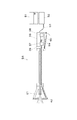
そこで、本願出願人は、特願2002−227086号において、図3に示す構成の静電噴霧装置を例示している。この静電噴霧装置は、薬液を収容する収容タンク51と、該収容タンク51から供給される薬液を加圧するポンプ52と、該ポンプ52の吐出口にホース53を介して接続された手持ち式ノズル部54とを備えている。手持ち式ノズル部54のグリップ部55は、ホース53からの薬液供給を制御するための薬液供給制御弁56と、直流高電圧を発生させるための高電圧発生装置57と、高電圧発生装置57の駆動源としての蓄電池58と、高電圧発生装置57の動作を制御する高電圧制御スイッチ59を内蔵するとともに、薬液供給制御弁56及び高電圧制御スイッチ59を操作するための一つの操作レバー60を備えている。そして、操作レバー60を同図の矢印方向に回動する(引き寄せる)と、薬液供給制御弁56及び高電圧制御スイッチ59が略同時に作動するようにすることにより、液滴を噴出しているときのみ、噴霧ノズル61及び電極62間に高電圧を印加するようにしている。このように、液体流路の弁と電気回路のスイッチとを同時に作動させるための構成は、例えば特許文献1にも開示されている。
【0004】
【特許文献1】
実公平7−51169号公報(第3頁、図5)
【0005】
【発明が解決しようとする課題】
ところが、高電圧制御スイッチ59や高電圧発生装置57等の高電圧関連の回路系統については、外部に対する漏電や防水等について十分な対策を講じる必要があるが、外部から人手によって操作される操作レバー60により高電圧制御スイッチ59が直接切り替えられるような構成では、その対策が不十分になったり、その対策のために構造が複雑化してコストが増大するという課題もある。
【0006】
また、従来の静電噴霧装置は、一つの操作レバー60の動きに連動して、薬液供給制御弁56と高電圧制御スイッチ59とが作動するように構成されているので、操作手段がこのような特定構造のものに限定されるとともに、操作レバー60、薬液供給制御弁56、及び高電圧制御スイッチ59がこの特定構造に適用可能な特定仕様のものに限定されてしまう。このため、操作手段設計上の制約が大きいという課題がある。
【0007】
本発明の目的は、上記課題を解決し、噴霧の出力と高電圧の発生とを連動させるとともに、高電圧関連の回路系統の制御と、薬液供給制御弁の制御とを構造的に分離することができる静電噴霧装置を提供することにある。
【0008】
【課題を解決するための手段】
上記目的を達成するために、本発明の静電噴霧装置は、液体を収容し供給するための液体供給部と、該液体供給部から供給される液体を加圧する液体圧力発生部と、該液体圧力発生部に接続され液体供給制御弁を有するノズル部と、該ノズル部の噴霧ノズルから噴出される液滴を帯電させるための高電圧発生装置とを備えた静電噴霧装置であって、前記液体供給制御弁と前記噴霧ノズルとの間における液体の流路に感圧センサーを挿入し、前記液体供給制御弁が開かれて該流路内の圧力が所定圧力以上になったことを該感圧センサーにより検知して、前記高電圧発生装置を作動させるように構成している。
【0009】
この構成によれば、液体の圧力を検知する前記感圧センサーにより、液体供給制御弁が開かれることによる噴霧出力の有無を検出して前記高電圧発生装置を作動させるようにしているので、該高電圧発生装置を含む高電圧関連の回路系統の制御と、前記薬液供給制御弁の制御とを構造的に分離することができる。このため、高電圧関連の回路系統の外部に対する漏電や防水等の対策が容易になる。しかも操作手段設計上の自由度も大きくなる。
【0010】
前記感圧センサーとしては、液体の圧力を検知するものであれば特に限定されないが、次の態様のものを例示する。
(a)液体の圧力による弾性体(例えば、ダイヤフラム、ベロー等)の変形を検出するように構成された態様。
(b)液体の圧力による固体の電気的な性質の変化(抵抗変化、起電力変化、静電容量変化等)を検出するように構成された態様。
(c)液体の圧力による固体(水晶等)の固有振動数の変化を検出するように構成された態様。
【0011】
前記(a)において、前記感圧センサーは、液体の圧力が前記所定圧力を越えたときにおける前記弾性体の過大な変形を抑制する抑制面を備えた態様を例示する。
【0012】
この構成によれば、前記抑制面は、前記弾性体の過大な変形を抑制するようになっているので、該弾性体に高強度のもの採用しなくても十分に液体の圧力に耐える構成とすることができる。
【0013】
なお、前記液体としては、土壌や植物等に散布する液体であれば特に限定されないが、薬液、液肥等を例示する。
【0014】
【発明の実施の形態】
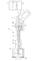
以下、本発明を具体化した一実施形態の静電噴霧装置について、図1及び図2を参照して説明する。図1は、本発明の静電噴霧装置の全体構成を示しており、本静電噴霧装置は、作物の病気や虫の防除用薬液を収容し供給するための薬液供給部としての収容タンク1と、該収容タンク1から供給される薬液を加圧する薬液圧力発生部としてのポンプ2と、該薬液圧力発生部の吐出口にホース3を介して接続された手持ち式ノズル部9とを備えている。ポンプ2としては、噴霧するための所定の噴霧圧力が得られるものであれば特に限定されないが、エンジンやモータ等の原動機で駆動されるものを例示する。
【0015】
手持ち式ノズル部9は、手持ち用のグリップ部4と、該グリップ部4の先端側に取り付けられた支持体としての噴管11と、該噴管11の先端にコネクタ14を介して着脱可能に接続されたノズルユニット15とを備えている。そして、ノズルユニット15は、本例では、導電性材料で形成された噴霧ノズル17と、該噴霧ノズル17から噴出される液滴の拡散範囲の外側に近接するように配設された電極としての環状電極19と、該環状電極19を噴霧ノズル17に結合する絶縁性材料からなる電極ホルダ18とを備え、これらが一体的に結合されてなっている。
【0016】
グリップ部4は、その基端側にホース3が接続され、該ホース3からの薬液供給を制御するための薬液供給制御弁5と、直流高電圧を発生させるための高電圧発生装置6と、高電圧発生装置6の駆動源としての蓄電池7と、高電圧発生装置6の動作を制御する感圧センサー8とを備えている。
【0017】
薬液供給制御弁5としては、本例では、いわゆるボールコックと呼ばれているものを採用しており、レバー5aを回動させることで薬液の流れを制御することができるようになっている。本例の薬液供給制御弁5は例示であり、その他の構造の弁(例えば、電磁弁等)やコックを適宜採用することができる。
【0018】
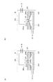
感圧センサー8は、図2に示すように、薬液供給制御弁5と噴霧ノズル17の間の液体の流路21に連通された圧力ケース22と、該圧力ケース22の開口を塞ぐように配設された弾性体としてのダイヤフラム23と、ダイヤフラム23が圧力ケース22の開口を密閉するように、圧力ケース22との間でダイヤフラム23を挾持するダイヤフラムホルダ24と、ダイヤフラム23の反圧力ケース側の面の中心に突設されており、ダイヤフラムホルダ24に形成された貫通穴24aに挿通された突起部25と、ダイヤフラム23により変位される突起部25によってレバー26aがON又はOFF側に変位されるように配設されたマイクロスイッチ26とを備えている。本例では、ダイヤフラム23として、ゴム(又は軟質樹脂)製の弾力がある円盤状に形成されたものを採用している。また、ダイヤフラムホルダ24の内面24bは、貫通穴24aを中心とするテーパー状に窪められており、これにより、図2(a)に示すように、薬液供給制御弁5が開かれることにより流路21内の圧力が所定圧力を少し越える程度に高くなるまではダイヤフラム23が密着しないように空間が形成された状態となる。この状態では、ダイヤフラム23中央の突起部25はマイクロスイッチ26のレバー26aを押していない(本例ではマイクロスイッチ26がOFF)。そして、薬液の圧力が所定圧力まで高くなると、図2(b)に示すようにダイヤフラム23及び突起部25が上向き矢印方向へ変位し、ダイヤフラム23中央の突起部25がマイクロスイッチ26のレバー26aを押すようになっている(本例ではマイクロスイッチ26がON)。さらに、薬液の圧力が所定圧力を少し越えると、ダイヤフラム23がダイヤフラムホルダ24の内面に密着するようになっている。つまり、ダイヤフラムホルダ24の内面24bは、ダイヤフラム23がそれ以上変位しないように変位を抑制するようになっており、この内面24bがダイヤフラム23の過大な変形を抑制する抑制面である(図2(b)参照)。本例では、このように作動されるマイクロスイッチ26のON/OFF信号を、高電圧発生装置6のON/OFF制御信号とするように構成している。
【0019】
以上のように構成された本実施形態の静電噴霧装置によれば、薬液の圧力を検知する感圧センサー8により、薬液供給制御弁5が開かれることによる噴霧出力の有無を検出して高電圧発生装置6を作動させるようにしているので、噴霧の出力と高電圧の発生とを連動させることができる。しかも、従来とは異なり、該高電圧発生装置6を含む高電圧関連の回路系統の制御と、薬液供給制御弁5の制御とを構造的に分離することができる。このため、高電圧関連の回路系統の外部に対する漏電や防水等の対策が容易になる。しかも操作手段設計上の自由度も大きくなる。
【0020】
また、ダイヤフラムホルダ24の内面24bは、ダイヤフラム23の過大な変形を抑制するようになっているので、該ダイヤフラム23に高強度のもの採用しなくても十分に薬液の圧力に耐える構成とすることができる。
【0021】
なお、本発明は前記実施形態に限定されるものではなく、発明の趣旨から逸脱しない範囲で適宜変更して具体化することもできる。
(1)静電噴霧装置を、例えば液肥の散布用に構成すること。
(2)ダイヤフラム23を利用した感圧センサーに代えて、他の構成や原理の感圧センサーを適宜採用すること。
(3)ノズル部を手持ち式ではなく、機体に支持させるように構成すること。
【0022】
【発明の効果】
本発明に係る静電噴霧装置によれば、噴霧の出力と高電圧の発生とを連動させるとともに、高電圧関連の回路系統の制御と、薬液供給制御弁の制御とを構造的に分離することができるという優れた効果を奏する。
【図面の簡単な説明】
【図1】本発明の一実施形態を示す静電噴霧装置の全体構成を示す断面図である。
【図2】同静電噴霧装置の感圧センサーの構成を示す断面図である。
【図3】従来の静電噴霧装置の全体構成を示す断面図である。
【符号の説明】
1 収容タンク
2 ポンプ
5 薬液供給制御弁
5a レバー
6 高電圧発生装置
7 蓄電池
8 感圧センサー
9 手持ち式ノズル部
17 噴霧ノズル
19 環状電極
21 流路
23 ダイヤフラム
24 ダイヤフラムホルダ
24b 内面
26 マイクロスイッチ[0001]
TECHNICAL FIELD OF THE INVENTION
TECHNICAL FIELD The present invention relates to an electrostatic spraying device that efficiently attaches liquid droplets of a liquid such as a chemical solution to agricultural products by using static electricity.
[0002]
[Prior art]
Electrostatic spraying devices use a high voltage to apply electric charges to droplets of chemicals and the like ejected from a spray nozzle, and move the droplets along the lines of electric force directed toward an object such as a plant to move the droplet onto the object. It is designed to adhere. As described above, a high voltage is applied to the spray nozzles of the electrostatic spraying device, and if a high voltage is applied to the spray nozzles even when the droplets are not ejected, the worker may carelessly touch the nozzles. Electric shock.
[0003]
Accordingly, the applicant of the present application exemplifies an electrostatic spraying device having a configuration shown in FIG. 3 in Japanese Patent Application No. 2002-227086. This electrostatic spraying device includes a
[0004]
[Patent Document 1]
Japanese Utility Model Publication No. 7-51169 (
[0005]
[Problems to be solved by the invention]
However, it is necessary to take sufficient countermeasures against leakage and waterproofing of the outside with respect to high-voltage-related circuit systems such as the high-
[0006]
Further, in the conventional electrostatic spraying device, the chemical liquid
[0007]
An object of the present invention is to solve the above-mentioned problems, to link the output of spray and the generation of high voltage, and to structurally separate control of a circuit system related to high voltage and control of a chemical liquid supply control valve. It is an object of the present invention to provide an electrostatic spraying device that can perform the above.
[0008]
[Means for Solving the Problems]
In order to achieve the above object, an electrostatic spraying device according to the present invention includes a liquid supply unit for containing and supplying a liquid, a liquid pressure generation unit for pressurizing the liquid supplied from the liquid supply unit, A nozzle unit connected to the pressure generating unit and having a liquid supply control valve, and an electrostatic spraying device including a high voltage generator for charging droplets ejected from a spray nozzle of the nozzle unit, A pressure-sensitive sensor is inserted into a liquid flow path between the liquid supply control valve and the spray nozzle, and the liquid supply control valve is opened to detect that the pressure in the flow path has become equal to or higher than a predetermined pressure. The high voltage generator is configured to operate by detecting the pressure with a pressure sensor.
[0009]
According to this configuration, since the pressure-sensitive sensor that detects the pressure of the liquid detects the presence or absence of the spray output due to the opening of the liquid supply control valve, and operates the high-voltage generating device. The control of the high-voltage-related circuit system including the high-voltage generator and the control of the chemical liquid supply control valve can be structurally separated. For this reason, it becomes easy to take measures such as earth leakage and waterproofing to the outside of the high voltage related circuit system. In addition, the degree of freedom in designing the operation means is increased.
[0010]
The pressure sensor is not particularly limited as long as it detects the pressure of the liquid, but the following embodiment is exemplified.
(A) An embodiment configured to detect deformation of an elastic body (for example, a diaphragm, a bellows, etc.) due to the pressure of a liquid.
(B) A mode configured to detect a change in electrical properties of a solid due to a pressure of a liquid (resistance change, electromotive force change, capacitance change, etc.).
(C) An embodiment configured to detect a change in the natural frequency of a solid (such as quartz) due to the pressure of a liquid.
[0011]
In the above (a), the pressure-sensitive sensor is exemplified by a mode having a suppression surface for suppressing excessive deformation of the elastic body when the pressure of the liquid exceeds the predetermined pressure.
[0012]
According to this configuration, the suppression surface is configured to suppress excessive deformation of the elastic body, so that the elastic body can sufficiently withstand liquid pressure without employing a high-strength elastic body. can do.
[0013]
The liquid is not particularly limited as long as it is a liquid sprayed on soil, plants, and the like, and examples thereof include a chemical solution and a liquid fertilizer.
[0014]
BEST MODE FOR CARRYING OUT THE INVENTION
Hereinafter, an electrostatic spraying device according to an embodiment of the present invention will be described with reference to FIGS. 1 and 2. FIG. 1 shows the overall configuration of an electrostatic spraying device according to the present invention. The electrostatic spraying device includes a
[0015]
The hand-held
[0016]
The grip part 4 has a
[0017]
In this example, a so-called ball cock is used as the chemical liquid
[0018]
As shown in FIG. 2, the pressure-
[0019]
According to the electrostatic spraying device of the present embodiment configured as described above, the presence or absence of the spray output due to the opening of the chemical liquid
[0020]
Further, since the
[0021]
Note that the present invention is not limited to the above-described embodiment, and can be embodied with appropriate modifications without departing from the spirit of the invention.
(1) The electrostatic spraying device is configured for spraying liquid fertilizer, for example.
(2) Instead of a pressure-sensitive sensor using the
(3) The nozzle unit is configured not to be hand-held but to be supported by the body.
[0022]
【The invention's effect】
ADVANTAGE OF THE INVENTION According to the electrostatic spraying apparatus which concerns on this invention, while making the output of a spray and generation | occurrence | production of a high voltage interlock | cooperate, control of the high voltage related circuit system and control of a chemical | medical solution supply control valve structurally separate. It has an excellent effect that it can be performed.
[Brief description of the drawings]
FIG. 1 is a cross-sectional view illustrating an overall configuration of an electrostatic spraying device according to an embodiment of the present invention.
FIG. 2 is a sectional view showing a configuration of a pressure-sensitive sensor of the electrostatic spraying device.
FIG. 3 is a cross-sectional view showing the overall configuration of a conventional electrostatic spraying device.
[Explanation of symbols]
DESCRIPTION OF
Claims (3)
該液体供給部から供給される液体を加圧する液体圧力発生部と、
該液体圧力発生部に接続され液体供給制御弁を有するノズル部と、
該ノズル部の噴霧ノズルから噴出される液滴を帯電させるための高電圧発生装置と
を備えた静電噴霧装置であって、
前記液体供給制御弁と前記噴霧ノズルとの間における液体の流路に感圧センサーを挿入し、前記液体供給制御弁が開かれて該流路内の圧力が所定圧力以上になったことを該感圧センサーにより検知して、前記高電圧発生装置を作動させるように構成した静電噴霧装置。A liquid supply unit for containing and supplying the liquid,
A liquid pressure generating unit that pressurizes the liquid supplied from the liquid supply unit,
A nozzle unit having a liquid supply control valve connected to the liquid pressure generating unit,
A high voltage generator for charging droplets ejected from a spray nozzle of the nozzle portion, comprising:
A pressure-sensitive sensor is inserted into a liquid flow path between the liquid supply control valve and the spray nozzle, and the liquid supply control valve is opened to confirm that the pressure in the flow path has become equal to or higher than a predetermined pressure. An electrostatic spraying device configured to operate the high-voltage generating device by detecting with a pressure-sensitive sensor.
Priority Applications (1)
| Application Number | Priority Date | Filing Date | Title |
|---|---|---|---|
| JP2002325864A JP2004160271A (en) | 2002-11-08 | 2002-11-08 | Electrostatic sprayer |
Applications Claiming Priority (1)
| Application Number | Priority Date | Filing Date | Title |
|---|---|---|---|
| JP2002325864A JP2004160271A (en) | 2002-11-08 | 2002-11-08 | Electrostatic sprayer |
Publications (1)
| Publication Number | Publication Date |
|---|---|
| JP2004160271A true JP2004160271A (en) | 2004-06-10 |
Family
ID=32804957
Family Applications (1)
| Application Number | Title | Priority Date | Filing Date |
|---|---|---|---|
| JP2002325864A Pending JP2004160271A (en) | 2002-11-08 | 2002-11-08 | Electrostatic sprayer |
Country Status (1)
| Country | Link |
|---|---|
| JP (1) | JP2004160271A (en) |
Cited By (7)
| Publication number | Priority date | Publication date | Assignee | Title |
|---|---|---|---|---|
| JP2007222729A (en) * | 2006-02-22 | 2007-09-06 | Minoru Industrial Co Ltd | Electrostatic sprayer |
| JP2008136416A (en) * | 2006-12-01 | 2008-06-19 | Agritecno Yazaki Co Ltd | Chemical sprayer |
| KR200459928Y1 (en) | 2010-03-04 | 2012-04-20 | 구기현 | Static electrostatic spray device |
| KR101323802B1 (en) | 2012-01-30 | 2013-10-31 | 한밭대학교 산학협력단 | Electrostatic Pesticide Nozzle |
| WO2016167410A1 (en) * | 2015-04-14 | 2016-10-20 | 김장환 | Long-distance electrostatic spray apparatus |
| WO2018139726A1 (en) * | 2017-01-26 | 2018-08-02 | 김장환 | Remote electrostatic automatic sprayer |
| CN112572803A (en) * | 2020-12-22 | 2021-03-30 | 苏州极目机器人科技有限公司 | Aviation electrostatic spraying device and system |
-
2002
- 2002-11-08 JP JP2002325864A patent/JP2004160271A/en active Pending
Cited By (9)
| Publication number | Priority date | Publication date | Assignee | Title |
|---|---|---|---|---|
| JP2007222729A (en) * | 2006-02-22 | 2007-09-06 | Minoru Industrial Co Ltd | Electrostatic sprayer |
| JP2008136416A (en) * | 2006-12-01 | 2008-06-19 | Agritecno Yazaki Co Ltd | Chemical sprayer |
| KR200459928Y1 (en) | 2010-03-04 | 2012-04-20 | 구기현 | Static electrostatic spray device |
| KR101323802B1 (en) | 2012-01-30 | 2013-10-31 | 한밭대학교 산학협력단 | Electrostatic Pesticide Nozzle |
| WO2016167410A1 (en) * | 2015-04-14 | 2016-10-20 | 김장환 | Long-distance electrostatic spray apparatus |
| CN106794478A (en) * | 2015-04-14 | 2017-05-31 | 金章焕 | Long range electrostatic spraying device |
| WO2018139726A1 (en) * | 2017-01-26 | 2018-08-02 | 김장환 | Remote electrostatic automatic sprayer |
| CN112572803A (en) * | 2020-12-22 | 2021-03-30 | 苏州极目机器人科技有限公司 | Aviation electrostatic spraying device and system |
| CN112572803B (en) * | 2020-12-22 | 2025-07-15 | 苏州极目机器人科技有限公司 | Aviation electrostatic spray device and system |
Similar Documents
| Publication | Publication Date | Title |
|---|---|---|
| EP2462833A2 (en) | Portable electrically-operated liquid-cosmetic mist dispenser | |
| AU2002230267A1 (en) | Liquid spray-head, apparatus comprising a liquid spray-head and container therefore | |
| EP1713592B1 (en) | Electrostatic spraying device | |
| EP3866984B1 (en) | Electrospinning devices and systems and methods thereof | |
| JP2004160271A (en) | Electrostatic sprayer | |
| EP1060800A2 (en) | Control device for high-pressure washers or the like | |
| JP4140825B2 (en) | Electrostatic spraying equipment | |
| KR20180022215A (en) | Portable mist device | |
| JP4441789B2 (en) | Electrostatic spraying equipment | |
| JP2006021148A (en) | Electrostatic sprayer | |
| JP2005193225A (en) | Electrostatic sprayer | |
| JP3420288B2 (en) | Switch unit for electrostatic gun, electrostatic gun and electrostatic coating device | |
| JP4441790B2 (en) | Earth leakage prevention member | |
| JP6203579B2 (en) | Liquid consumption device | |
| JP2009022891A (en) | Electrostatic spraying equipment | |
| JP4992097B2 (en) | Electrostatic spraying equipment | |
| JP2006175397A (en) | Electrostatic spraying apparatus | |
| JP5066677B2 (en) | Electrostatic spray device and nozzle tube cover | |
| JPH1028664A (en) | Cleaner especially for domestic use | |
| KR20150070535A (en) | ReChargeable Steam Cleaner with air-pump | |
| CN106040473B (en) | The electric air pump handle cover of sprayer | |
| JPS5911828A (en) | Change-over operation apparatus for endoscope | |
| CN215784196U (en) | Electrostatic liquid spraying device | |
| CN218394203U (en) | Fluid sprayer | |
| CN216019093U (en) | Atomizer protection device |
Legal Events
| Date | Code | Title | Description |
|---|---|---|---|
| A621 | Written request for application examination |
Effective date: 20050105 Free format text: JAPANESE INTERMEDIATE CODE: A621 |
|
| A131 | Notification of reasons for refusal |
Effective date: 20080212 Free format text: JAPANESE INTERMEDIATE CODE: A131 |
|
| A02 | Decision of refusal |
Effective date: 20080701 Free format text: JAPANESE INTERMEDIATE CODE: A02 |