JP2004156972A - Positive displacement flowmeter - Google Patents
Positive displacement flowmeter Download PDFInfo
- Publication number
- JP2004156972A JP2004156972A JP2002321738A JP2002321738A JP2004156972A JP 2004156972 A JP2004156972 A JP 2004156972A JP 2002321738 A JP2002321738 A JP 2002321738A JP 2002321738 A JP2002321738 A JP 2002321738A JP 2004156972 A JP2004156972 A JP 2004156972A
- Authority
- JP
- Japan
- Prior art keywords
- light
- rotor
- rotation
- positive displacement
- optical path
- Prior art date
- Legal status (The legal status is an assumption and is not a legal conclusion. Google has not performed a legal analysis and makes no representation as to the accuracy of the status listed.)
- Granted
Links
Images


Abstract
Description
【0001】
【発明の属する技術分野】
本発明は、容積式流量計に関し、より詳細には、光学式で回転子の回転を検出することで被測定流体の容積流量を測定する容積式流量計に関する。
【0002】
【従来の技術】
周知のように、容積流量計は、被測定流体が流入、流出する計量室と、その計量室内で回転する回転子等の運動子(以下、回転子で説明する)を備えている。回転子は、計量室とで定められる基準の流体体積を排出する。計量室を通過する流量は回転子の回転に比例した流量であり、流入する流体のフローパターンに影響されない高精度の流量を測定できる。回転子の回転は、磁気接手等の回転伝達機構を介して液密に流量表示器に機械的に伝達する方法と、回転子の回転を、光学的,電磁的,磁気的等に回転子の位置を検出する位置検出器を用いて検出して、直接回転信号を流量パルスとして出力する方法とに大別される。
【0003】
回転子の回転を機械的に伝達する方法は、回転伝達機構が回転子の負荷となるため、誤差要因となり、特に小型の流量計には不適である。そこで、小型流量計では位置検出器を有する方式、特に電磁的又は磁気的に位置を検出する磁気検出方式は、測定流体の性状に影響されることなく検出できるので容積流量計の流量検出の主流をなしている。そのなかでも、流量計回転子に埋設された磁石の磁力を、隔板を介して接液外に配置した感磁素子に与えてこれを働かせるようにした磁気感知方式が一般的に採用されている(例えば、特許文献1を参照)。
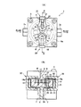
【0004】
図8は、従来技術による、磁気感知方式を採用した容積式流量計の一例を示す図であり、図8(A)は図8(B)の矢視A−A線断面図、図8(B)は図8(A)の矢視B−B線断面図である。図8中、50は容積流量計、53は端面板、54は筐体(外筐)、55は磁気センサ、60は計量室、61は流入口、62は流出口、63,63′は回転子、63aは回転子63の端面、64,64′は回転子軸、65,65′は回転子の歯車部(噛合部)、66,67は磁石である。
【0005】
容積流量計50は、外筐54と、端面板53と、外筐54及び端面版53により形成される空間に相当する計量室60と、及び計量室60内に配設され回転子軸64,64′まわりにそれぞれ回転可能に支持される回転子63,63′とをその主要な構成要素とする。計量室60は、流入口61及び流出口62に連通した外筐54の内壁と、開口した外筐54を封止するために外筐54に取り付けられた非磁性材からなる端面板53とにより構成される。また、計量室60内には、回転子軸64,64′が垂直に且つ互いに平行に埋設され、回転子軸64に回転可能に支持された非円形歯車の回転子63及び回転子軸64′に回転可能に支持された非円形歯車の回転子63′が各々噛合するよう配設されている。また、回転子63の端面63aの長径上には軸対称な位置に磁石66,67が埋設されている。このように、計量室60内で流入する流体の体積に比例して回転する回転子63の端面63aに、柱状の磁石66,67を圧入して磁石66,67の磁束が端面板53に配設された磁性センサ55により検出できるようにしている。
【0006】
上述のごとき磁気検出方式では、被測定流体が、磁石に対して腐蝕性を持っていた場合には耐蝕処置を施さなければならないため高価になることや、流量計が小型になった場合、回転子本体よりも密度の大きな磁石を埋め込むため、回転子が重くなるという問題点があると共に、一部の感磁素子では磁気吸引のため推力(スラスト方向の力)又はトルク損失が発生して小流量域における器差が大きくなるなどの問題点がある。さらに、設置された磁石どうしの干渉の他に、内部に設置された磁石と外部に設置された磁石などとの干渉から可動部負荷を生ずる上に、周囲磁場、周囲磁気によりセンサが誤検出を起こすこともある。
【0007】
これらの問題点は、上述した光学式の位置検出方式を採用することで解決できるものとされてきた。実際に、光学的に回転子の位置を検出する方式を採用し、回転子の回転操作を、光を利用して計測するようにした容積式流量計には様々なものが提案されている(例えば、特許文献2を参照)。
【0008】
図9は、従来技術による、光学式位置検出方式を採用した容積式流量計の一例を示す図であり、図9(A)は容積式流量計の縦断正面図、図9(B)は図9(A)の矢視B−B線断面図、図9(C)は容積式流量計においてしばしば存在する欠陥部分を説明するための、図9(A)の矢視B−B線断面図である。図9中、70は容積式流量計、74は光透過性をもたない筐体(外筐)、75,76は外筐74に配設した光路、77は光源、78は受光部、80は計量室、81は流入口、82は流出口、83,83′は回転子、84,84′は回転子軸、85,85′は回転子の歯車部(噛合部)、86,87,86′,87′は回転子に配設した光路である。図8で説明した容積式流量計と異なる点は、磁石及び磁気センサの代わりに光学的な位置検出手段を設けたところであり、その他の部分の説明は省略する。
【0009】
光路86は、回転子83の回転方向を横切る方向に穿った光路で、図示では一方の回転子83に対し回転子軸84と平行した方向に穿ってあるが、光路86は回転子軸84とは必ずしも平行である必要はなく、斜め方向に穿っても差支えなく、しかも図示したように両方の回転子83,83′に穿ってもよい。さらにまた、光路は、回転子につき1箇所だけでなく、光路86,87,86′,87′として図示のように、1つの回転子につき回転子軸に対称な位置に複数穿っても差支えない。一方、光路75,76は、容積式流量計70の外筐74において光路86の延長上で同一線上に配設した、流体が漏れない構成の光路で、石英ガラス,光ファイバなどを埋設して形成する。光源77が一方の光路75の外側に配置され、センサなどの受光部78が他方の光路76の外側に配置されている。なお、この例では、非円形歯車を一対の回転子とした容積式流量計に用いた場合を示したが、他の容積式流量計、例えばルーツ型などの回転子を有する全てのこの種の流量計に適用できることは勿論である。
【0010】
上述のごとき構成に基づいて、容積式流量計70の作用を説明する。被測定流体が容積式流量計70内を流入口81より流出口82に向かって流れると、回転子83,83′が回転する。回転子83には光路86が穿ってあるので、回転の度毎に容積式流量計70の外筐74の光路75,76を横切る。光路75,76上には、光源77と受光部78が配設されてあるので、光路86が同一線上に達すると光源77からの光を受光部78が受光し、これを検出することができる。したがって、回転子83の回転数に応じた受光作用が行われるので、受光部78での受光検知を積算計数すれば、流量に比例した積算計数を知ることができる。しかも回転子83に穿った光路86は、その設置数を増やせばより微細な計数が可能となるので、測定精度を向上できる。
【0011】
しかしながら、上述の容積式流量計70においては、光路75,76用の孔を外筐74に設け、且つ光路75,76を接着剤などで固定する必要があり、その結果、光路75,76をその孔に固定する際に、図9(C)で示すようにその計量室側(回転子83側)の端面75a,76aがずれることがある。このずれにより、計量室80(の内壁)に余計なスペースを作り、計量室80の容積を変えてしまったり、場合によっては被測定流体が漏れるときもある。これらの結果として器差が大きくなり、この器差は流量計が小型(小口径)になるに従って無視し難いものとして現れることとなる。
【0012】
また、光学的位置検出方式において、発光部(光源)や受光部に光ファイバを用いた光学式流量検出機構を設けた場合には、光ファイバの曲がりの悪さから、容積式流量計の筐体が大きくなってしまう。
【0013】
【特許文献1】
特開平7−12613号公報
【特許文献2】
実開昭56−124829号公報
【0014】
【発明が解決しようとする課題】
上述のごとく、従来の容積式流量計においては、特に小流量域用の小型容積式流量計において、光学式,磁気式,電磁式の位置検出方式のいずれを採用した場合でも器差が大きくなり、特に微流量域で測定精度を確保できないといった問題や、容積式流量計がコンパクト且つ軽量にならないという問題が生じる。
【0015】
本発明は、上述のごとき実情を鑑みてなされたものであり、器差の小さい、小流量域用の容積式流量計を提供することをその目的とする。
【0016】
また、本発明は、器差が小さく、且つコンパクト化及び軽量化を実現した、小流量域用の容積式流量計を提供することを他の目的とする。
【0017】
【課題を解決するための手段】
本発明は、上述の目的を達成するために、被測定流体の流入口及び流出口と開口部とを有する計量室と、該計量室に流入する被測定流体の体積に比例して回転する回転子と、前記計量室を覆う外筐となる、前記開口部を封止する蓋部と前記流入口及び流出口に連通した流入部及び流出部とをもつ筐体と、該筐体の外側から前記回転子の回転を光学的に検出する回転検出手段とを備え、被測定流体の流量を測定する容積式流量計であって、前記筐体は光透過性のある材質で形成し、前記回転子は、少なくとも1つの光路をもち、該光路以外を光透過性のない材質で形成し、前記計量室の外壁は、前記回転子の回転に伴って回転する前記光路の一延長線上に、光透過性をもつ材質で形成した透光路をもち、該透光路以外を光透過性のない材質で形成したことを特徴としたものである。また、前記回転検出手段は、前記光路及び透光路を通して光を送受し、前記回転子の回転に伴う光の断続信号をとりだす光電センサを有するようにし、コンパクト化及び軽量化を実現するようにしてもよい。また、前記筐体は、該筐体の外側の対向面に、前記回転検出手段を取り付けるための取付け部を有するようにして、組み立てやメンテナンスを容易としてもよい。さらに、前記取付け部の一方又は双方に、前記回転検出手段における受光位置又は光の送受位置に相当する領域を除いて光を遮蔽する光遮蔽部を設け、光の拡散による回転検出精度の劣化を防ぐようにしてもよい。
【0018】
また、本発明は、他の形態として、被測定流体の流入口及び流出口と開口部とを有する計量室と、該計量室に流入する被測定流体の体積に比例して回転する回転子と、前記計量室の前記開口部を封止する蓋と、前記計量室を構成する外筐と前記蓋とにより構成される筐体の外側から、前記回転子の回転を光学的に検出する回転検出手段とを備え、被測定流体の流量を測定する容積式流量計であって、前記筐体は光透過性のある材質で形成し、前記回転子は光透過性のない材質で形成したことを特徴としたものである。また、前記回転検出手段は、前記回転子の回転に伴い該回転子が断続的に遮断する光路上で、光を送受し、前記回転子の回転に伴う光の断続信号をとりだす光電センサを有するようにし、コンパクト化及び軽量化を実現するようにしてもよい。また、前記筐体は、該筐体の外側の対向面に、前記回転検出手段を取り付けるための取付け部を有するようにして、組み立てやメンテナンスを容易としてもよい。さらに、前記取付け部の一方又は双方に、前記回転検出手段における受光位置又は光の送受位置に相当する領域を除いて光を遮蔽する光遮蔽部を設け、光の拡散による回転検出精度の劣化を防ぐようにしてもよい。
【0019】
【発明の実施の形態】
図1乃至図3は、本発明の一実施形態に係る容積式流量計の一構成例を示す図で、図1(A)は図1(B)のA方向からみた容積式流量計本体の正面図、図1(B)は図1(A)のB方向からみた容積式流量計本体の側面図、図2は本発明に係る容積式流量計に取り付ける流量測定部の一例を示す図、図3は図1の本体に図2の流量測定部を取り付けた容積式流量計を示す図である。図3(A)はその正面図、図3(B)はその矢視B−B断面図である。なお、図中、透き通って見える部材を点線で示している。
【0020】
本発明の一実施形態に係る容積式流量計は、計量室内部に配設された回転子の動き(可動計量部における動き)を光学的に検知することで、計量室内部を流動する被測定流体の体積を測定し、被測定流体の流量(又は流速)を演算して出力する流量計であり、容積式流量計本体の外筐を光透過性のある材質で構成したことを特徴とする。以下、本実施形態に係る容積式流量計を図1乃至図3の構成例に基づき説明する。ただし、図1乃至図3の構成例においては、回転子として一対の非円形回転子(非円形歯車回転子)を適用した容積式流量計を例示するが、他の容積式流量計、例えばルーツ型などの回転子を有する全てのこの種の流量計に適用できることは勿論である。
【0021】
本構成例の容積式流量計の本体1は、その筐体を構成する筐体本体4と蓋(端面板)3とにより、その外形をなしている。それらの接合にはここではネジ5を使用した例を示しているが、接着剤などを使用しても、それらを併用してもよい。筐体は、計量室18の開口部10を封止する蓋部3と、流入部11,流出部12をもつ筐体本体4とからなり、計量室18を覆う外筐となる。この筐体は、光透過性(透光性)のある材質で形成されている。流入部11,流出部12は、それぞれ管接続部2a,2bに通じている。計量室18は、被測定流体の流入口及び流出口と開口部10とを有する。筐体本体4は次で説明する開口部と、流入口に連通する流入部11と、流出口に連通する流出部12とをもつ凹状体である。開口部には計量室18が埋め込まれ、計量室18に設けられた流入口,流出口にそれぞれ流入部11,流出部12がそれぞれ接続される。さらに、端面板3により計量室18の開口部10が封止されている。すなわち、筐体本体4には、筐体本体4及び端面板3とで構成される内部空間に、凹部として開口部10を形成した計量室18を内包している。計量室18における計量空間は、流入口及び流出口をもつ計量室18の内壁と、計量室18の開口部10を封止するために計量室18の鍔部18aに接して筐体本体4に取り付けられた端面板3とにより形成されることとなる。
【0022】
また、計量室18は、回転子の回転に伴って回転する光路の一延長線上(光路と相対する位置)に、流体が漏れない構成をもつ透光性材質で形成した透光路19をもち、透光路19以外を光透過性のない材質で形成している。透光路19は、貫通孔を穿ち、それを樹脂等のモールド材でモールドするとよい。
【0023】
計量空間には、回転子軸14,14′が垂直に且つ互いに平行に埋設され、回転子軸14,14′まわりにそれぞれ回転可能に支持される非円形歯車(ここでは楕円形歯車)の回転子13,13′が各々噛合部15,15′で噛合するよう配設されている。この状態で、回転子13,13′は、計量室18の計量空間(開口部10に相当)に流入する被測定流体の体積に比例して回転する。回転子13には、回転方向を横切る方向(垂直でなくてもよい)に少なくとも1つの光路16(又は光路16,17;以下同じ)をもつ。すなわち、流体の移送によって回転する回転子に、その回転の方向を横切る方向に光路16を穿つ。この光路16は、樹脂等のモールド材でモールドしてもよいが単なる貫通孔とすることが好ましい。そして、その光路16以外を光透過性のない材質で形成する。このようにして、柱状の光路16を介して、端面板3,筐体本体4の外側の凹部6,7に配設された光電センサ20により回転が検出できるようにしている。回転子13′に関しても、回転子の製造効率を上げるため、また重量バランスを保つために、光路16′(又は光路16′,17′;以下同じ)を形成してもよい。
【0024】
このように、光路16は、回転子13の回転方向を横切る方向に穿った貫通孔で、図示では一方の回転子13に対し回転子軸14と平行した方向に穿ってあるが、光路16は軸14とは必ずしも平行である必要はなく、斜め方向に穿っても差支えなく、しかもバランスや生産性を鑑みて図示したように両方の回転子13,13′に穿ってもよい。さらにまた、光路は、回転子につき1箇所だけでなく、光路16,17,16′,17′として図示のように、1つの回転子につき回転子軸に対称な位置に複数穿っても差支えない。一方、光路19は、容積式流量計本体1の計量室18において光路16が回転により通過するラインの延長上で同一線上に配設した、流体が漏れない構成の光路で、石英ガラス,光ファイバなどを埋設して形成してもよい。なお、計量室18の底璧を反射式にしてもよい(光電センサも反射型にする)。このように、光電センサ20として透過型のものを説明したが、いずれかに鏡を設けるなどして、反射型のものを採用してもよい。
【0025】
流量測定部における回転検出手段は、筐体の外側から回転子の回転を(回転子の所定位置を対象として)光学的に検出する。回転検出手段は、光路16及び透光路19を通して光を送受し、回転子の回転に伴う光の断続信号をとりだすことを可能としている。この光の断続信号は、ここではその好適な例である光電センサ20によりとりだすものを例示している。また、光電センサ20は、図1及び図2で矢視の方向に取り付ける例を示すように、組み立てやメンテナンスの点から着脱自在に装着可能とすることが好ましい。そのため、筐体は、その外側の対向面(筐体本体3側の面及び蓋部4側の面)に、回転検出手段を取り付けるための取付け部6,7を有するようにしている。
【0026】
次に、光電センサ20についてその概略を説明する。光電センサ20には、LED等で構成される発光部(光源)24,受光部25がそれぞれ光電センサ本体(センサ支持部)21の延伸部(アーム)22,23に取り付けられており、容積式流量計本体1にこの光電センサ20を装着する際には、光源24が一方の上側凹部6の外側に配置され、センサなどの受光部25が他方の下側凹部7の外側に配置されるように装着される。このように、延伸部22は、端面板3の上側凹部6に装着し、位置決めの容易さから、回転子13の長軸が回転子軸14,14′を結んだ線上で、光路16が通過する位置に、そのセンサ部(例えば発光部/受光部)が配置されるように設けることが可能な長さをもつ。同様に延伸部23は、筐体本体4の下側凹部7に装着し、同様に光路19にそのセンサ部(例えば受光部/発光部)が配置されるように設けることが可能な長さをもつ。このようにこの光電センサ20は、いずれの方向でも取り付け可能なようにすることも可能である。光電センサ20を採用することで、光ファイバ等を用いるのに比べて、測定部の軽量化及びコンパクト化を図れ、軽量化させることにより、容積式流量計での微流量域の精度確保(微小流域の器差改善)が可能となる。また、光電センサ20には、センサ支持部21又は外部に図示しない演算部を備え、また容積式流量計としては図示しない流量表示部がさらに備えられている。
【0027】
最終的に、光電センサによって、流量に応じて回転する回転子(回転歯車)の回転を検出する。回転歯車は透明な筐体内に収納されており、且つ、最低1箇所に貫通孔が設けられている。光電センサは、好ましくは着脱自在に装着可能で、装着時、回転歯車が1回転する毎に、光電センサの発光部からの光が貫通孔を通して受光部に達し、回転歯車の回転数に応じた電気パルス信号を発生する。図1及び図2は、光電センサを流量計本体から取り外した時の様子を示している。
【0028】
上述のごとく、本実施形態に係る容積式流量計においては、容器を透過のものとし、光電センサ等により、可動計量部を検知、出力させ、流量演算とするので、磁石を要さずに済み、さらに可動部を軽量化させることで、より小流域の器差改善を得ることが可能となる。すなわち、光源よりの光を回転子の光路が一致した時にのみ受光部に伝達させて回転子の回転数を計数するようにしたので、全く抵抗のない計数が可能となる上に、その構成も回転子には光路を形成するだけでよく、しかも流量計本体の外筐には透光路を設けて発光部と受光部を接続するだけでよいので頗る簡易となり、量産性に適するなど、被測定流体の種類(濁度なども含む)にも全く影響されない汎用性のある流体測定が可能となる。特に小型の流量計では、光路のために設けた孔が回転子の軽量化につながるので小流量域での機器特性が著しく改善される。
【0029】
実際の器差に関しては、例えば、同じサイズの磁気検出式の容積式流量計が0.5l/h〜10l/h(極差±2%)の流量範囲に対応するのに対し、本実施形態の容積式流量計は、0.1l/h〜10l/h(極差±1%)の極小流量(微小流量)からの流量範囲に対応することが可能となる。すなわち、磁気検出式では流量のレンジが1:10(良くても1:20)だったのに対し、本実施形態では流量のレンジが1:100になり、よって精度が向上する。
【0030】
図4は、本発明の他の実施形態に係る容積式流量計の一構成例を示す図で、図2の流量測定部を取り付けた容積式流量計を示す図である。図4(A)はその正面図、図4(B)はその矢視B−B断面図である。なお、図中、透き通って見える部材を点線で示し、透明な部分の一部を透明を表すハッチングで示している。本発明の他の実施形態に係る容積式流量計においては、図1乃至図3で説明した実施形態において、回転子13(13′)に光路16,17(16′,17′)の他に光路を設け、分解能を高く(ハイパルス化)したことを特徴としており、その実施形態と異なる部分のみ説明する。
【0031】
図4で示すように、回転子13の光路として回転子につき1箇所や2箇所だけでなく、光路16,17,16′,17′の他の光路として図示のように、1つの回転子につき回転子軸に対称な位置に複数(ここでは6個)穿っても差支えない。さらに、バランスや生産性を鑑みて図示したように両方の回転子13,13′に穿ってもよい。本実施形態により、光電センサ20等の回転検出手段による回転検出の分解能を高くすることができる。
【0032】
図5は、本発明の他の実施形態に係る容積式流量計の一構成例を示す図で、図2の流量測定部を取り付けた容積式流量計を示す図である。図5(A)はその正面図、図5(B)はその矢視B−B断面図、図5(C)は容積式流量計本体の取付け部に設ける光遮蔽部の一例を示す図である。なお、図中、透き通って見える部材を点線で示し、透明な部分の一部を透明を表すハッチングで示している。
本発明の他の実施形態に係る容積式流量計においては、図1乃至図4で説明した各実施形態において、取付け部6,7の一方又は双方に、回転検出手段における受光位置又は光の送受位置に相当する領域を除いて光を遮蔽する光遮蔽部を設けたことを特徴としており、その実施形態と異なる部分のみ説明する。本実施形態によれば、透明部分での光の拡散による回転検出精度の劣化を防ぐことが可能となる。
【0033】
本実施形態においては、筐体本体4の上側凹部6の外側、及び/又は、下側凹部7の外側に、光遮蔽部(遮光部ともいう)26を設け、特に回転子13(13′)に設けられた光路の数が多い場合(図4参照)の光の拡散防止を行うようにしている。勿論回転子13(13′)の光路が1つの場合にも適用可能である。本実施形態における筐体は、その外側の対向面(筐体本体3側の面及び蓋部4側の面)に、回転検出手段を取り付けるための取付け部6,7(上側凹部6,下側凹部7)を備える必要がある。この遮光部26は塗料や板などからなり、図5(B)に示すように少なくとも光電センサ20でいうと受光部25側に設けることで、光の拡散を防止できるが、上述のごとく発光部24側に設けてもよい。ただし、光の送受に係わる光路上に相当する領域(光電センサ20の機能に影響がでる領域)には図5(C)に示すように孔27を設ける必要がある。
【0034】
図6は、本発明の他の実施形態に係る容積式流量計の一構成例を示す図で、図2の流量測定部を取り付けた容積式流量計を示す図である。図6(A)はその正面図、図6(B)はその矢視B−B断面図である。なお、図中、透き通って見える部材を点線で示し、透明な部分の一部を透明を表すハッチングで示している。本発明の他の実施形態に係る容積式流量計においては、図1乃至図5で説明した各実施形態において、光電センサ等の回転検出手段を各回転子13,13′の双方に設け分解能を高く(ハイパルス化)したことを特徴としており、その実施形態と異なる部分のみ説明する。
【0035】
本実施形態における筐体は、その外側の対向面(筐体本体3側の面及び蓋部4側の面)に、回転検出手段を取り付けるための取付け部6,7(上側凹部6,下側凹部7)を、もう一対(取付け部6′,7′)備えている。取付け部6′,7′には、光電センサ20と同様の光電センサ20′が、好ましくは着脱可能に嵌め込まれている。
【0036】
図7は、本発明の他の実施形態に係る容積式流量計の一構成例を示す図で、図2の流量測定部を取り付けた容積式流量計を示す図である。図7(A)はその正面図、図7(B)はその矢視B−B断面図である。なお、図中、透き通って見える部材を点線で示し、透明な部分の一部を透明を表すハッチングで示している。本発明の他の実施形態に係る容積式流量計においては、図1乃至図6で説明した各実施形態において、回転子以外を全て光透過性をもつ材質としたことを特徴としており、その実施形態と異なる部分のみ説明する。
【0037】
計量室(本実施形態では計量空間を指す)は、被測定流体の流入部(ここでは流入口ともいえる)11及び流出部(ここでは流出口ともいえる)12と開口部10とを有し、蓋部3により、計量室の開口部10が封止されている。流入口11,流出口12は、それぞれ管接続部2a,2bに通じている。回転検出手段は、計量室を構成する外筐(筐体本体)4と蓋部3とにより構成される筐体の外側から、回転子の回転を光学的に検出する。この回転検出手段は、図1乃至図6で説明した実施形態と同様に、回転子13(又は13′;以下同じ)の回転に伴い回転子13が断続的に遮断する光路上で、光を送受し、回転子13の回転に伴う光の断続信号をとりだす光電センサ20を有するようにしてもよい。そして、筐体(蓋3及び外筐4)は光透過性のある材質で形成し、回転子13は光透過性のない材質で形成している。このように、本実施形態では、回転子13以外を全て光透過性をもつ材質としている。すなわち図1乃至図6で説明した各実施形態において計量室も一体にしている。
【0038】
ただし、本実施形態においては、例えば図3の透光路19や光路16,17,16′,17′を必要としない。この場合、回転子13が断続的に遮断する光路とは、回転子13の回転方向を横切る方向に加え、回転に水平な方向でも良くなる。ただし、回転子には、光路16,17,16′,17′等の光路を備えてもよい。
【0039】
本実施形態に係る容積式流量計においては、図1乃至図6で説明した実施形態の効果に加えて、回転子以外を全て光透過性をもつ材質としているので(計量室も一体にしているので)、内壁側光路の取付けによって生じる計量室の容積に基づく器差を防止することが可能となり、測定精度をさらに向上させることが可能となる。さらに、本実施形態によれば、製造工程が少なくて済む利点もある。
【0040】
【発明の効果】
本発明によれば、器差の小さい、小流量域用の容積式流量計を提供することができる。
【0041】
また、本発明によれば、器差が小さく、且つコンパクト化及び軽量化を実現した、小流量域用の容積式流量計を提供することができる。
【図面の簡単な説明】
【図1】本発明の一実施形態に係る容積式流量計の一構成例を示す図で、容積式流量計本体の正面図及び側面図である。
【図2】本発明に係る容積式流量計に取り付ける流量測定部の一例を示す図である。
【図3】図1の本体に図2の流量測定部を取り付けた容積式流量計を示す図である。
【図4】本発明の他の実施形態に係る容積式流量計の一構成例を示す図である。
【図5】本発明の他の実施形態に係る容積式流量計の一構成例を示す図である。
【図6】本発明の他の実施形態に係る容積式流量計の一構成例を示す図である。
【図7】本発明の他の実施形態に係る容積式流量計の一構成例を示す図である。
【図8】従来技術による、磁気感知方式を採用した容積式流量計の一例を示す図である。
【図9】従来技術による、光学式位置検出方式を採用した容積式流量計の一例を示す図である。
【符号の説明】
1…容積式流量計本体、2a,2b…管接続部、3…蓋部(端面板)、4…筐体本体、5…ネジ、6…端面板の外側の凹部(取付け部)、7…筐体本体の外側の凹部(取付け部)、10…開口部、11…流入部、12…流出部、13,13′…回転子、14,14′…回転子軸、15,15′…噛合部、16,16′,17,17′…光路、18…計量室、18a…計量室の鍔部、19…光路、20…光電センサ、21…光電センサ本体(センサ支持部)、22,23…延伸部(アーム)、24…発光部(光源)、25…受光部、26…光遮蔽部、27…光遮蔽部の孔。[0001]
TECHNICAL FIELD OF THE INVENTION
The present invention relates to a positive displacement flowmeter, and more particularly, to a positive displacement flowmeter that measures the volume flow rate of a fluid to be measured by optically detecting the rotation of a rotor.
[0002]
[Prior art]
As is well known, a positive displacement flowmeter is provided with a measuring chamber into and out of which a fluid to be measured flows, and a rotor (hereinafter, referred to as a rotor) such as a rotor rotating in the measuring chamber. The rotor discharges a reference fluid volume defined by the metering chamber. The flow rate passing through the measuring chamber is a flow rate proportional to the rotation of the rotor, and a highly accurate flow rate that is not affected by the flow pattern of the flowing fluid can be measured. Rotation of the rotor is performed by a method of mechanically transmitting the rotation of the rotor to the flow indicator in a liquid-tight manner through a rotation transmission mechanism such as a magnetic joint, or by optically, electromagnetically, magnetically, or the like. The method is broadly divided into a method of detecting a position using a position detector and directly outputting a rotation signal as a flow rate pulse.
[0003]
The method of mechanically transmitting the rotation of the rotor causes an error because the rotation transmission mechanism acts as a load on the rotor, and is not suitable for a small flow meter. Therefore, a small flow meter that has a position detector, especially a magnetic detection method that detects position electromagnetically or magnetically, can be detected without being affected by the properties of the fluid to be measured. Has made. Among them, a magnetic sensing method is generally adopted in which a magnetic force of a magnet embedded in a flow meter rotor is applied to a magnetic sensing element arranged outside liquid contact via a partition plate so that the magnetic sensing element works. (For example, see Patent Document 1).
[0004]
FIG. 8 is a diagram showing an example of a positive displacement type flow meter adopting a magnetic sensing method according to the related art. FIG. 8 (A) is a sectional view taken along line AA of FIG. 8 (B). FIG. 8B is a cross-sectional view taken along line BB of FIG. 8,
[0005]
The
[0006]
In the magnetic detection method as described above, if the fluid to be measured has a corrosive property with respect to the magnet, it must be subjected to anticorrosion treatment, so that it becomes expensive. The rotor has a problem that the rotor becomes heavier because a magnet having a higher density than the main body is embedded. In addition, some magnetic sensing elements generate thrust (force in the thrust direction) or torque loss due to magnetic attraction. There are problems such as an increase in instrumental difference in the flow rate range. Furthermore, in addition to the interference between the installed magnets, the interference between the magnets installed inside and the magnets installed outside causes a load on the movable part, and the sensor detects erroneous detection due to the surrounding magnetic field and magnetism. It can happen.
[0007]
It has been considered that these problems can be solved by employing the above-described optical position detection method. In fact, various types of positive displacement flowmeters that adopt a method of optically detecting the position of the rotor and measure the rotation operation of the rotor using light have been proposed ( For example, see Patent Document 2).
[0008]
FIG. 9 is a view showing an example of a positive displacement type flow meter adopting an optical position detection system according to the prior art. FIG. 9 (A) is a vertical sectional front view of the positive displacement type flow meter, and FIG. 9 (A) is a sectional view taken along the line BB of FIG. 9 (C), and FIG. 9 (C) is a sectional view taken along the line BB of FIG. 9 (A) for explaining defective portions often present in the positive displacement flowmeter. It is. 9,
[0009]
The
[0010]
The operation of the
[0011]
However, in the
[0012]
Also, in the optical position detection method, when an optical flow rate detection mechanism using an optical fiber is provided in the light emitting section (light source) and the light receiving section, the housing of the positive displacement type flow meter is provided due to poor bending of the optical fiber. Becomes large.
[0013]
[Patent Document 1]
JP-A-7-12613
[Patent Document 2]
Japanese Utility Model Publication No. 56-124829
[0014]
[Problems to be solved by the invention]
As described above, in the conventional positive displacement flowmeter, especially in a small positive displacement flowmeter for a small flow rate region, the instrumental difference becomes large even when any of the optical, magnetic, and electromagnetic position detection methods is adopted. In particular, there arises a problem that the measurement accuracy cannot be ensured particularly in a minute flow rate region, and a problem that the volumetric flow meter is not compact and lightweight.
[0015]
The present invention has been made in view of the above circumstances, and has as its object to provide a positive displacement flowmeter for a small flow rate region with a small instrumental difference.
[0016]
Another object of the present invention is to provide a positive displacement flowmeter for a small flow rate region, which has a small instrumental difference, and is compact and lightweight.
[0017]
[Means for Solving the Problems]
In order to achieve the above object, the present invention provides a measuring chamber having an inlet and an outlet for a fluid to be measured and an opening, and a rotation rotating in proportion to the volume of the fluid to be measured flowing into the measuring chamber. And a housing having an inflow portion and an outflow portion communicating with the lid and the inflow port and the outflow port, which serve as an outer casing that covers the measuring chamber, and a lid that seals the opening, from the outside of the casing. Rotation detection means for optically detecting the rotation of the rotor, a positive displacement flowmeter for measuring the flow rate of the fluid to be measured, wherein the housing is formed of a light transmissive material, The child has at least one optical path, and the other than the optical path is formed of a material having no light transmissivity. The outer wall of the measuring chamber is provided with an optical path on one extension of the optical path that rotates with the rotation of the rotor. It has a light-transmitting path formed of a transmissive material, and other than the light-transmitting path is formed of a material having no light transmitting property. Is obtained is characterized in that the. Further, the rotation detecting means has a photoelectric sensor which transmits and receives light through the optical path and the light transmitting path, and takes out an intermittent signal of light accompanying rotation of the rotor, thereby realizing compactness and light weight. You may. Further, the housing may have a mounting portion for mounting the rotation detecting means on an outer facing surface of the housing to facilitate assembly and maintenance. Further, one or both of the mounting portions are provided with a light shielding portion for shielding light except for a region corresponding to a light receiving position or a light transmitting / receiving position in the rotation detecting means, to prevent deterioration of rotation detection accuracy due to diffusion of light. It may be prevented.
[0018]
According to another aspect of the present invention, there is provided a measuring chamber having an inlet and an outlet and an opening for a fluid to be measured, and a rotor that rotates in proportion to the volume of the fluid to be measured flowing into the measuring chamber. Rotation detection for optically detecting the rotation of the rotor from outside a housing configured by a lid that seals the opening of the measurement chamber and an outer case and the lid that constitute the measurement chamber. Means for measuring the flow rate of the fluid to be measured, wherein the housing is formed of a light-transmitting material, and the rotor is formed of a non-light-transmitting material. It is a characteristic. Further, the rotation detecting means has a photoelectric sensor that transmits and receives light on an optical path that the rotor intermittently interrupts with the rotation of the rotor, and extracts an intermittent signal of the light according to the rotation of the rotor. In this way, compactness and weight reduction may be realized. Further, the housing may have a mounting portion for mounting the rotation detecting means on an outer facing surface of the housing to facilitate assembly and maintenance. Further, one or both of the mounting portions are provided with a light shielding portion for shielding light except for a region corresponding to a light receiving position or a light transmitting / receiving position in the rotation detecting means, to prevent deterioration of rotation detection accuracy due to diffusion of light. It may be prevented.
[0019]
BEST MODE FOR CARRYING OUT THE INVENTION
1 to 3 are views showing an example of the configuration of a positive displacement flowmeter according to an embodiment of the present invention. FIG. 1A is a view of a positive displacement flowmeter main body viewed from a direction A in FIG. 1B is a side view of the positive displacement type flowmeter main body viewed from a direction B in FIG. 1A, FIG. 2 is a diagram showing an example of a flow rate measuring unit attached to the positive displacement type flowmeter according to the present invention, FIG. 3 is a diagram showing a positive displacement type flow meter in which the flow measuring unit of FIG. 2 is attached to the main body of FIG. FIG. 3A is a front view thereof, and FIG. 3B is a sectional view taken along line BB of FIG. In the drawings, the members that can be seen transparently are indicated by dotted lines.
[0020]
The positive displacement flowmeter according to one embodiment of the present invention optically detects the movement of the rotor (movement in the movable measuring section) disposed inside the measuring chamber, thereby measuring the flow in the measuring chamber. A flowmeter for measuring a volume of a fluid, calculating and outputting a flow rate (or a flow velocity) of a fluid to be measured, wherein an outer casing of a main body of the positive displacement type flowmeter is formed of a light-transmitting material. . Hereinafter, the positive displacement flowmeter according to the present embodiment will be described based on the configuration examples of FIGS. 1 to 3. However, in the configuration examples of FIGS. 1 to 3, a positive displacement flow meter to which a pair of non-circular rotors (non-circular gear rotors) is applied as a rotor is exemplified, but other positive displacement flow meters, for example, roots Of course, it can be applied to all such flow meters having a rotor such as a mold.
[0021]
The main body 1 of the positive displacement type flowmeter of this configuration example has an outer shape formed by a housing
[0022]
The measuring
[0023]
In the metering space,
[0024]
As described above, the
[0025]
The rotation detecting means in the flow measuring unit optically detects the rotation of the rotor from outside the housing (for a predetermined position of the rotor). The rotation detecting means transmits and receives the light through the
[0026]
Next, an outline of the
[0027]
Finally, the rotation of the rotor (rotating gear) that rotates according to the flow rate is detected by the photoelectric sensor. The rotating gear is housed in a transparent housing, and has at least one through hole. The photoelectric sensor is preferably detachably mountable, and when mounted, every time the rotating gear rotates once, light from the light emitting unit of the photoelectric sensor reaches the light receiving unit through the through-hole, and corresponds to the rotation speed of the rotating gear. Generate an electrical pulse signal. 1 and 2 show a state when the photoelectric sensor is detached from the flowmeter main body.
[0028]
As described above, in the positive displacement type flow meter according to the present embodiment, the container is transparent, and the movable measuring unit is detected and output by the photoelectric sensor or the like, and the flow rate calculation is performed. Therefore, the magnet is not required. Further, by reducing the weight of the movable part, it is possible to improve the instrumental difference in a smaller basin. That is, the light from the light source is transmitted to the light receiving section only when the optical path of the rotor coincides, and the number of rotations of the rotor is counted, so that counting without any resistance is possible, and the configuration is also improved. It is only necessary to form an optical path in the rotor, and furthermore, it is only necessary to provide a light transmitting path in the outer casing of the flowmeter body and connect the light emitting unit and the light receiving unit, which is extremely simple and suitable for mass production. A versatile fluid measurement that is completely unaffected by the type of the measurement fluid (including turbidity, etc.) can be performed. In particular, in a small flow meter, the hole provided for the optical path leads to a reduction in the weight of the rotor, so that the device characteristics in a small flow rate region are significantly improved.
[0029]
Regarding the actual instrumental difference, for example, the magnetic detection type positive displacement flowmeter of the same size corresponds to a flow rate range of 0.5 l / h to 10 l / h (polar difference ± 2%), whereas the present embodiment Is capable of coping with a flow rate range from a minimum flow rate (micro flow rate) of 0.1 l / h to 10 l / h (± 1%). That is, in the magnetic detection method, the flow rate range is 1:10 (at best 1:20), but in the present embodiment, the flow rate range is 1: 100, and the accuracy is improved.
[0030]
FIG. 4 is a diagram illustrating a configuration example of a positive displacement flowmeter according to another embodiment of the present invention, and is a diagram illustrating a positive displacement flowmeter to which the flow rate measuring unit in FIG. 2 is attached. FIG. 4A is a front view thereof, and FIG. 4B is a sectional view taken along the line BB of FIG. In the drawings, transparent members are indicated by dotted lines, and a part of the transparent part is indicated by hatching indicating transparency. In the positive displacement type flow meter according to another embodiment of the present invention, in addition to the
[0031]
As shown in FIG. 4, the optical path of the
[0032]
FIG. 5 is a diagram illustrating a configuration example of a positive displacement flowmeter according to another embodiment of the present invention, and is a diagram illustrating a positive displacement flowmeter to which the flow measurement unit in FIG. 2 is attached. 5A is a front view, FIG. 5B is a cross-sectional view taken along the line BB, and FIG. 5C is a view showing an example of a light shielding portion provided on a mounting portion of the positive displacement flowmeter main body. is there. In the drawings, transparent members are indicated by dotted lines, and a part of the transparent part is indicated by hatching indicating transparency.
In the positive displacement flowmeter according to another embodiment of the present invention, in each of the embodiments described with reference to FIGS. 1 to 4, one or both of the mounting
[0033]
In the present embodiment, a light shielding portion (also referred to as a light shielding portion) 26 is provided outside the upper concave portion 6 of the
[0034]
FIG. 6 is a diagram illustrating a configuration example of a positive displacement flowmeter according to another embodiment of the present invention, and is a diagram illustrating a positive displacement flowmeter to which the flow measurement unit in FIG. 2 is attached. FIG. 6A is a front view thereof, and FIG. 6B is a sectional view taken along the line BB of FIG. In the drawings, transparent members are indicated by dotted lines, and a part of the transparent part is indicated by hatching indicating transparency. In the positive displacement flowmeter according to another embodiment of the present invention, in each of the embodiments described with reference to FIGS. 1 to 5, a rotation detecting means such as a photoelectric sensor is provided on both of the
[0035]
The housing according to the present embodiment has mounting portions 6 and 7 (upper recess 6 and lower side 6) for mounting rotation detecting means on the outer facing surfaces (the surface on the
[0036]
FIG. 7 is a diagram illustrating a configuration example of a positive displacement flowmeter according to another embodiment of the present invention, and is a diagram illustrating a positive displacement flowmeter to which the flow rate measuring unit in FIG. 2 is attached. FIG. 7A is a front view thereof, and FIG. 7B is a sectional view taken along line BB of FIG. In the drawings, transparent members are indicated by dotted lines, and a part of the transparent part is indicated by hatching indicating transparency. A positive displacement flowmeter according to another embodiment of the present invention is characterized in that, in each of the embodiments described with reference to FIGS. 1 to 6, all parts except the rotor are made of a material having light transmittance. Only parts different from the embodiment will be described.
[0037]
The measuring chamber (refers to the measuring space in the present embodiment) has an inflow portion (also referred to as an inflow port) 11 and an outflow portion (here, also referred to as an outflow port) 12 of the fluid to be measured, and an
[0038]
However, in the present embodiment, for example, the
[0039]
In the positive displacement type flow meter according to the present embodiment, in addition to the effects of the embodiment described with reference to FIGS. 1 to 6, all parts other than the rotor are made of a light-transmitting material (the measuring chamber is also integrated). Therefore, it is possible to prevent an instrumental difference based on the volume of the measuring chamber caused by the attachment of the inner wall side optical path, and it is possible to further improve the measurement accuracy. Further, according to the present embodiment, there is an advantage that the number of manufacturing steps can be reduced.
[0040]
【The invention's effect】
According to the present invention, it is possible to provide a positive displacement flowmeter for a small flow rate region with a small instrumental difference.
[0041]
Further, according to the present invention, it is possible to provide a positive displacement flowmeter for a small flow rate region, which has a small instrumental difference, and is compact and lightweight.
[Brief description of the drawings]
FIG. 1 is a diagram showing one configuration example of a positive displacement flowmeter according to one embodiment of the present invention, and is a front view and a side view of a positive displacement flowmeter main body.
FIG. 2 is a view showing an example of a flow rate measuring unit attached to the positive displacement type flow meter according to the present invention.
FIG. 3 is a diagram showing a positive displacement type flow meter in which the flow measuring unit of FIG. 2 is attached to the main body of FIG. 1;
FIG. 4 is a diagram illustrating a configuration example of a positive displacement flowmeter according to another embodiment of the present invention.
FIG. 5 is a diagram showing one configuration example of a positive displacement flowmeter according to another embodiment of the present invention.
FIG. 6 is a diagram showing a configuration example of a positive displacement flowmeter according to another embodiment of the present invention.
FIG. 7 is a diagram showing a configuration example of a positive displacement flowmeter according to another embodiment of the present invention.
FIG. 8 is a diagram showing an example of a positive displacement type flow meter employing a magnetic sensing method according to the related art.
FIG. 9 is a diagram showing an example of a positive displacement type flow meter employing an optical position detection method according to the related art.
[Explanation of symbols]
DESCRIPTION OF SYMBOLS 1 ... Volumetric flow meter main body, 2a, 2b ... Pipe connection part, 3 ... Lid part (end face plate), 4 ... Housing main body, 5 ... Screw, 6 ... Outer recess of end face plate (attachment part), 7 ... Concave part (attachment part) on the outside of the housing main body, 10 ... opening part, 11 ... inflow part, 12 ... outflow part, 13, 13 '... rotor, 14, 14' ... rotor shaft, 15, 15 '... meshing Parts, 16, 16 ', 17, 17': optical path, 18: measuring chamber, 18a: flange of measuring chamber, 19: optical path, 20: photoelectric sensor, 21: photoelectric sensor main body (sensor supporting part), 22, 23 ... Extended part (arm), 24 ... Light emitting part (light source), 25 ... Light receiving part, 26 ... Light shielding part, 27 ... Hole of light shielding part.
Claims (6)
前記筐体は光透過性のある材質で形成し、
前記回転子は、少なくとも1つの光路をもち、該光路以外を光透過性のない材質で形成し、
前記計量室の外壁は、前記回転子の回転に伴って回転する前記光路の一延長線上に、光透過性をもつ材質で形成した透光路をもち、該透光路以外を光透過性のない材質で形成したことを特徴とする容積式流量計。A measuring chamber having an inlet and an outlet and an opening for the fluid to be measured, a rotor that rotates in proportion to the volume of the fluid to be measured flowing into the measuring chamber, and an outer casing that covers the measuring chamber, A housing having a lid for sealing the opening, an inflow portion and an outflow portion communicating with the inflow port and the outflow port, and rotation detection for optically detecting rotation of the rotor from outside the housing; Means, and a positive displacement flowmeter for measuring the flow rate of the fluid to be measured,
The housing is formed of a light transmissive material,
The rotator has at least one optical path, and is formed of a material having no optical transparency except for the optical path,
The outer wall of the weighing chamber has a light-transmitting path formed of a material having a light-transmitting property on one extension of the light path rotating with the rotation of the rotor, and has a light-transmitting property other than the light-transmitting path. A positive displacement flowmeter characterized by being formed of a non-material.
前記筐体は光透過性のある材質で形成し、前記回転子は光透過性のない材質で形成したことを特徴とする容積式流量計。A measuring chamber having an inlet and an outlet for the fluid to be measured and an opening, a rotor rotating in proportion to the volume of the fluid to be measured flowing into the measuring chamber, and sealing the opening of the measuring chamber; And a rotation detecting means for optically detecting the rotation of the rotor from the outside of the housing formed by the outer housing and the lid constituting the measuring chamber, and the flow rate of the fluid to be measured is provided. A volume flow meter for measuring,
The case is formed of a material having light transmittance, and the rotor is formed of a material having no light transmittance.
Priority Applications (1)
| Application Number | Priority Date | Filing Date | Title |
|---|---|---|---|
| JP2002321738A JP3667314B2 (en) | 2002-11-05 | 2002-11-05 | Positive displacement flowmeter |
Applications Claiming Priority (1)
| Application Number | Priority Date | Filing Date | Title |
|---|---|---|---|
| JP2002321738A JP3667314B2 (en) | 2002-11-05 | 2002-11-05 | Positive displacement flowmeter |
Publications (2)
| Publication Number | Publication Date |
|---|---|
| JP2004156972A true JP2004156972A (en) | 2004-06-03 |
| JP3667314B2 JP3667314B2 (en) | 2005-07-06 |
Family
ID=32802176
Family Applications (1)
| Application Number | Title | Priority Date | Filing Date |
|---|---|---|---|
| JP2002321738A Expired - Lifetime JP3667314B2 (en) | 2002-11-05 | 2002-11-05 | Positive displacement flowmeter |
Country Status (1)
| Country | Link |
|---|---|
| JP (1) | JP3667314B2 (en) |
Cited By (3)
| Publication number | Priority date | Publication date | Assignee | Title |
|---|---|---|---|---|
| JP2010107302A (en) * | 2008-10-29 | 2010-05-13 | Oval Corp | Volumetric flow meter |
| JP2013532837A (en) * | 2010-08-06 | 2013-08-19 | イーコラブ ユーエスエー インコーポレイティド | Flowmeter |
| CN106989785A (en) * | 2017-04-17 | 2017-07-28 | 惠州市铂蓝德科技有限公司 | A kind of closestool photo-electric water flow sensor |
-
2002
- 2002-11-05 JP JP2002321738A patent/JP3667314B2/en not_active Expired - Lifetime
Cited By (3)
| Publication number | Priority date | Publication date | Assignee | Title |
|---|---|---|---|---|
| JP2010107302A (en) * | 2008-10-29 | 2010-05-13 | Oval Corp | Volumetric flow meter |
| JP2013532837A (en) * | 2010-08-06 | 2013-08-19 | イーコラブ ユーエスエー インコーポレイティド | Flowmeter |
| CN106989785A (en) * | 2017-04-17 | 2017-07-28 | 惠州市铂蓝德科技有限公司 | A kind of closestool photo-electric water flow sensor |
Also Published As
| Publication number | Publication date |
|---|---|
| JP3667314B2 (en) | 2005-07-06 |
Similar Documents
| Publication | Publication Date | Title |
|---|---|---|
| JP6126001B2 (en) | Flowmeter | |
| US4489615A (en) | Fluid flow meter | |
| JP4183096B2 (en) | Path structure related to flow of fluid to be measured and differential pressure detection in servo volumetric flowmeter | |
| EP2128574B1 (en) | Pump unit type servo-displacement flowmeter | |
| KR200443454Y1 (en) | Flowmeter having Antipollution Element | |
| JP3667314B2 (en) | Positive displacement flowmeter | |
| KR101924426B1 (en) | Leakage checker for gas meter | |
| JP3063809B2 (en) | Volumetric flow meter | |
| JPH03257329A (en) | Flowmeter | |
| JP4245414B2 (en) | Rotation detector, positive displacement flow meter, and rotation detection method | |
| CN108827413B (en) | Roots flowmeter | |
| JP4881066B2 (en) | Flowmeter | |
| EP2286186B1 (en) | Diaphragm flow meter with rotating magnets | |
| RU207873U1 (en) | Liquid volume counter | |
| GB2101219A (en) | Rotary fluid-flow meter | |
| CN205537797U (en) | Flow count device | |
| KR20090000932U (en) | Flowmeter | |
| CA3004875A1 (en) | Counter module adaptor assembly for rotary gas meters | |
| CN216559143U (en) | Metering device with dual metering signal outputs | |
| JPH0316026Y2 (en) | ||
| JPH0438262Y2 (en) | ||
| JPS58127125A (en) | Flowmeter | |
| JPH0543384Y2 (en) | ||
| US924437A (en) | Gas-meter. | |
| KR20180092229A (en) | Volumetric flowmeter using rotator and piston method |
Legal Events
| Date | Code | Title | Description |
|---|---|---|---|
| A977 | Report on retrieval |
Free format text: JAPANESE INTERMEDIATE CODE: A971007 Effective date: 20041101 |
|
| A131 | Notification of reasons for refusal |
Free format text: JAPANESE INTERMEDIATE CODE: A131 Effective date: 20041109 |
|
| A521 | Request for written amendment filed |
Free format text: JAPANESE INTERMEDIATE CODE: A523 Effective date: 20050107 |
|
| TRDD | Decision of grant or rejection written | ||
| A01 | Written decision to grant a patent or to grant a registration (utility model) |
Free format text: JAPANESE INTERMEDIATE CODE: A01 Effective date: 20050405 |
|
| A61 | First payment of annual fees (during grant procedure) |
Free format text: JAPANESE INTERMEDIATE CODE: A61 Effective date: 20050405 |
|
| R150 | Certificate of patent or registration of utility model |
Free format text: JAPANESE INTERMEDIATE CODE: R150 Ref document number: 3667314 Country of ref document: JP Free format text: JAPANESE INTERMEDIATE CODE: R150 |
|
| FPAY | Renewal fee payment (event date is renewal date of database) |
Free format text: PAYMENT UNTIL: 20090415 Year of fee payment: 4 |
|
| R250 | Receipt of annual fees |
Free format text: JAPANESE INTERMEDIATE CODE: R250 |
|
| FPAY | Renewal fee payment (event date is renewal date of database) |
Free format text: PAYMENT UNTIL: 20090415 Year of fee payment: 4 |
|
| FPAY | Renewal fee payment (event date is renewal date of database) |
Free format text: PAYMENT UNTIL: 20100415 Year of fee payment: 5 |
|
| R250 | Receipt of annual fees |
Free format text: JAPANESE INTERMEDIATE CODE: R250 |
|
| FPAY | Renewal fee payment (event date is renewal date of database) |
Free format text: PAYMENT UNTIL: 20110415 Year of fee payment: 6 |
|
| R250 | Receipt of annual fees |
Free format text: JAPANESE INTERMEDIATE CODE: R250 |
|
| FPAY | Renewal fee payment (event date is renewal date of database) |
Free format text: PAYMENT UNTIL: 20110415 Year of fee payment: 6 |
|
| FPAY | Renewal fee payment (event date is renewal date of database) |
Free format text: PAYMENT UNTIL: 20120415 Year of fee payment: 7 |
|
| R250 | Receipt of annual fees |
Free format text: JAPANESE INTERMEDIATE CODE: R250 |
|
| FPAY | Renewal fee payment (event date is renewal date of database) |
Free format text: PAYMENT UNTIL: 20130415 Year of fee payment: 8 |
|
| R250 | Receipt of annual fees |
Free format text: JAPANESE INTERMEDIATE CODE: R250 |
|
| FPAY | Renewal fee payment (event date is renewal date of database) |
Free format text: PAYMENT UNTIL: 20140415 Year of fee payment: 9 |
|
| R250 | Receipt of annual fees |
Free format text: JAPANESE INTERMEDIATE CODE: R250 |
|
| R250 | Receipt of annual fees |
Free format text: JAPANESE INTERMEDIATE CODE: R250 |
|
| R250 | Receipt of annual fees |
Free format text: JAPANESE INTERMEDIATE CODE: R250 |
|
| R250 | Receipt of annual fees |
Free format text: JAPANESE INTERMEDIATE CODE: R250 |
|
| R250 | Receipt of annual fees |
Free format text: JAPANESE INTERMEDIATE CODE: R250 |
|
| R250 | Receipt of annual fees |
Free format text: JAPANESE INTERMEDIATE CODE: R250 |
|
| R250 | Receipt of annual fees |
Free format text: JAPANESE INTERMEDIATE CODE: R250 |
|
| R250 | Receipt of annual fees |
Free format text: JAPANESE INTERMEDIATE CODE: R250 |
|
| R250 | Receipt of annual fees |
Free format text: JAPANESE INTERMEDIATE CODE: R250 |
|
| R250 | Receipt of annual fees |
Free format text: JAPANESE INTERMEDIATE CODE: R250 |
|
| EXPY | Cancellation because of completion of term |