JP2004156458A - EGR gas flow rate estimation device for internal combustion engine - Google Patents
EGR gas flow rate estimation device for internal combustion engine Download PDFInfo
- Publication number
- JP2004156458A JP2004156458A JP2002320406A JP2002320406A JP2004156458A JP 2004156458 A JP2004156458 A JP 2004156458A JP 2002320406 A JP2002320406 A JP 2002320406A JP 2002320406 A JP2002320406 A JP 2002320406A JP 2004156458 A JP2004156458 A JP 2004156458A
- Authority
- JP
- Japan
- Prior art keywords
- flow rate
- egr
- egr gas
- pressure
- gas
- Prior art date
- Legal status (The legal status is an assumption and is not a legal conclusion. Google has not performed a legal analysis and makes no representation as to the accuracy of the status listed.)
- Granted
Links
Images


Classifications
-
- F—MECHANICAL ENGINEERING; LIGHTING; HEATING; WEAPONS; BLASTING
- F02—COMBUSTION ENGINES; HOT-GAS OR COMBUSTION-PRODUCT ENGINE PLANTS
- F02D—CONTROLLING COMBUSTION ENGINES
- F02D41/00—Electrical control of supply of combustible mixture or its constituents
- F02D41/0025—Controlling engines characterised by use of non-liquid fuels, pluralities of fuels, or non-fuel substances added to the combustible mixtures
- F02D41/0047—Controlling exhaust gas recirculation [EGR]
- F02D41/0065—Specific aspects of external EGR control
- F02D41/0072—Estimating, calculating or determining the EGR rate, amount or flow
-
- F—MECHANICAL ENGINEERING; LIGHTING; HEATING; WEAPONS; BLASTING
- F02—COMBUSTION ENGINES; HOT-GAS OR COMBUSTION-PRODUCT ENGINE PLANTS
- F02D—CONTROLLING COMBUSTION ENGINES
- F02D41/00—Electrical control of supply of combustible mixture or its constituents
- F02D41/02—Circuit arrangements for generating control signals
- F02D41/14—Introducing closed-loop corrections
- F02D41/1438—Introducing closed-loop corrections using means for determining characteristics of the combustion gases; Sensors therefor
- F02D41/1444—Introducing closed-loop corrections using means for determining characteristics of the combustion gases; Sensors therefor characterised by the characteristics of the combustion gases
- F02D41/1448—Introducing closed-loop corrections using means for determining characteristics of the combustion gases; Sensors therefor characterised by the characteristics of the combustion gases the characteristics being an exhaust gas pressure
- F02D41/145—Introducing closed-loop corrections using means for determining characteristics of the combustion gases; Sensors therefor characterised by the characteristics of the combustion gases the characteristics being an exhaust gas pressure with determination means using an estimation
-
- F—MECHANICAL ENGINEERING; LIGHTING; HEATING; WEAPONS; BLASTING
- F02—COMBUSTION ENGINES; HOT-GAS OR COMBUSTION-PRODUCT ENGINE PLANTS
- F02D—CONTROLLING COMBUSTION ENGINES
- F02D41/00—Electrical control of supply of combustible mixture or its constituents
- F02D41/0025—Controlling engines characterised by use of non-liquid fuels, pluralities of fuels, or non-fuel substances added to the combustible mixtures
- F02D41/0047—Controlling exhaust gas recirculation [EGR]
- F02D41/0065—Specific aspects of external EGR control
- F02D2041/0067—Determining the EGR temperature
- F02D2041/007—Determining the EGR temperature by estimation
-
- F—MECHANICAL ENGINEERING; LIGHTING; HEATING; WEAPONS; BLASTING
- F02—COMBUSTION ENGINES; HOT-GAS OR COMBUSTION-PRODUCT ENGINE PLANTS
- F02D—CONTROLLING COMBUSTION ENGINES
- F02D2200/00—Input parameters for engine control
- F02D2200/02—Input parameters for engine control the parameters being related to the engine
- F02D2200/04—Engine intake system parameters
- F02D2200/0402—Engine intake system parameters the parameter being determined by using a model of the engine intake or its components
-
- F—MECHANICAL ENGINEERING; LIGHTING; HEATING; WEAPONS; BLASTING
- F02—COMBUSTION ENGINES; HOT-GAS OR COMBUSTION-PRODUCT ENGINE PLANTS
- F02D—CONTROLLING COMBUSTION ENGINES
- F02D2200/00—Input parameters for engine control
- F02D2200/02—Input parameters for engine control the parameters being related to the engine
- F02D2200/04—Engine intake system parameters
- F02D2200/0406—Intake manifold pressure
-
- F—MECHANICAL ENGINEERING; LIGHTING; HEATING; WEAPONS; BLASTING
- F02—COMBUSTION ENGINES; HOT-GAS OR COMBUSTION-PRODUCT ENGINE PLANTS
- F02D—CONTROLLING COMBUSTION ENGINES
- F02D2200/00—Input parameters for engine control
- F02D2200/02—Input parameters for engine control the parameters being related to the engine
- F02D2200/04—Engine intake system parameters
- F02D2200/0414—Air temperature
- F02D2200/0416—Estimation of air temperature
-
- F—MECHANICAL ENGINEERING; LIGHTING; HEATING; WEAPONS; BLASTING
- F02—COMBUSTION ENGINES; HOT-GAS OR COMBUSTION-PRODUCT ENGINE PLANTS
- F02D—CONTROLLING COMBUSTION ENGINES
- F02D41/00—Electrical control of supply of combustible mixture or its constituents
- F02D41/0002—Controlling intake air
- F02D41/0007—Controlling intake air for control of turbo-charged or super-charged engines
-
- F—MECHANICAL ENGINEERING; LIGHTING; HEATING; WEAPONS; BLASTING
- F02—COMBUSTION ENGINES; HOT-GAS OR COMBUSTION-PRODUCT ENGINE PLANTS
- F02M—SUPPLYING COMBUSTION ENGINES IN GENERAL WITH COMBUSTIBLE MIXTURES OR CONSTITUENTS THEREOF
- F02M26/00—Engine-pertinent apparatus for adding exhaust gases to combustion-air, main fuel or fuel-air mixture, e.g. by exhaust gas recirculation [EGR] systems
- F02M26/02—EGR systems specially adapted for supercharged engines
- F02M26/04—EGR systems specially adapted for supercharged engines with a single turbocharger
- F02M26/05—High pressure loops, i.e. wherein recirculated exhaust gas is taken out from the exhaust system upstream of the turbine and reintroduced into the intake system downstream of the compressor
-
- Y—GENERAL TAGGING OF NEW TECHNOLOGICAL DEVELOPMENTS; GENERAL TAGGING OF CROSS-SECTIONAL TECHNOLOGIES SPANNING OVER SEVERAL SECTIONS OF THE IPC; TECHNICAL SUBJECTS COVERED BY FORMER USPC CROSS-REFERENCE ART COLLECTIONS [XRACs] AND DIGESTS
- Y02—TECHNOLOGIES OR APPLICATIONS FOR MITIGATION OR ADAPTATION AGAINST CLIMATE CHANGE
- Y02T—CLIMATE CHANGE MITIGATION TECHNOLOGIES RELATED TO TRANSPORTATION
- Y02T10/00—Road transport of goods or passengers
- Y02T10/10—Internal combustion engine [ICE] based vehicles
- Y02T10/40—Engine management systems
Landscapes
- Engineering & Computer Science (AREA)
- Chemical & Material Sciences (AREA)
- Combustion & Propulsion (AREA)
- Mechanical Engineering (AREA)
- General Engineering & Computer Science (AREA)
- Exhaust-Gas Circulating Devices (AREA)
- Combined Controls Of Internal Combustion Engines (AREA)
Abstract
【課題】EGR制御弁を介して吸気通路に流入するEGRガスの流量を、EGRガスとEGR通路間の管摩擦分を考慮することにより精度良く推定することができる内燃機関のEGRガス流量推定装置を提供すること
【解決手段】本装置は、機関の排気通路と吸気通路とに接続された排気還流管と、同排気還流管に介装された絞り部を有するEGR制御弁とを備えた内燃機関のEGRガス流量推定装置である。本装置は、排気圧力をPex、吸気圧をPb、絞り部の有効開口面積をAegr、EGRガスの密度をρa、EGRガスの比熱比をκとするとき、Gegr0=Aegr・(2・Pex・ρa)1/2・Φ、Φ=(((κ/(κ−1))・((Pb/Pex)2/ κ−(Pb/Pex)(1+1/ κ )))1/2なる一般式により暫定EGRガス流量Gegr0を推定する。そして、差圧(Pex−Pb)に応じる補正値dPgainを暫定EGRガス流量Gegr0に乗じて吸気通路に流入するEGRガス流量Gegrを推定する。
【選択図】 図4An EGR gas flow rate estimating apparatus for an internal combustion engine, which can accurately estimate a flow rate of EGR gas flowing into an intake passage via an EGR control valve by considering a pipe friction between the EGR gas and the EGR passage. An internal combustion engine includes: an exhaust gas recirculation pipe connected to an exhaust passage and an intake passage of an engine; and an EGR control valve having a throttle section interposed in the exhaust gas recirculation pipe. 1 is an EGR gas flow rate estimation device for an engine. When the exhaust pressure is Pex, the intake pressure is Pb, the effective opening area of the throttle portion is Aegr, the density of the EGR gas is ρa, and the specific heat ratio of the EGR gas is κ, Gegr0 = Aegr · (2 · Pex · ρa) 1/2 · Φ, Φ = (((κ / (κ−1)) · ((Pb / Pex) 2 / κ− (Pb / Pex) (1 + 1 / κ ) )) 1/2 The EGR gas flow Gegr0 flowing into the intake passage is estimated by multiplying the provisional EGR gas flow Gegr0 by the correction value dPgain corresponding to the differential pressure (Pex-Pb).
[Selection diagram] Fig. 4
Description
【0001】
【発明の属する技術分野】
本発明は、内燃機関の排気還流管から吸気通路に流入するEGRガスの流量を推定する内燃機関のEGRガス流量推定装置に関する。
【0002】
【従来の技術】
従来より、内燃機関から排出される窒素酸化物(NOx)の量を低減するため、同内燃機関の排ガスの一部を排気還流管を介して吸気通路に循環させるEGR装置が広く知られている。EGR装置は、火花点火式内燃機関及びディーゼル機関の何れにも適用される。この場合、EGRガス流量は、排気還流管に介装されたEGR制御弁の開度(有効開口断面積)を可変とすることにより制御されている。
【0003】
このようなEGR装置は、吸気通路に流入するEGRガス流量を推定するとともに同吸気通路に流入する新気流量を測定し、同推定したEGRガス流量と同測定した新気流量とに基いて、機関に吸入される総べてのガス(即ち、新気とEGRガスとの混合ガスであり、以下「吸気」とも称呼する。)の流量に対する同EGRガス流量の比であるEGR率を求め、このEGR率に基いてEGRガス流量を制御するようになっている。従って、EGRガス流量の制御等の機関制御において、吸気通路に流入するEGRガス流量を精度良く推定することは極めて重要である。そこで、従来の装置は、EGR制御弁の前後差圧と同EGR制御弁の開度とに基いて、前記EGRガス流量を推定するようになっている(例えば、特許文献1参照。)。
【0004】
【特許文献1】
特開2001−280202号公報(
【0005】及び第4頁)
【0006】
【発明が解決しようとする課題】
上記従来の装置は、吸気通路に配設されたブーストセンサ(吸気圧センサ)により検出された圧力とEGR制御弁の上流側の適宜位置に配設された圧力センサにより検出された圧力との差圧を前記前後差圧として使用し、前記EGRガス流量を推定するようになっている。しかしながら、EGR制御弁の直前及び直後の差圧とEGRガス量の推定に使用する前記前後差圧とが、EGRガスと排気還流管との間に生じる管摩擦により大きく相違することがあり、この場合、EGRガス流量を精度良く推定できないという問題がある。
【0007】
特に、圧縮性流体が絞り部(EGR制御弁)を通過する場合の同圧縮性流体の絞り部通過流量を同絞り部直前の上流側における同圧縮性流体の圧力及び同絞り部直後の下流側における同圧縮性流体の圧力とに基いて表す同圧縮性流体の絞り部通過流量に関する一般式を用いることにより、EGR制御弁を通過するEGRガスの流量(従って、吸気通路に流入するEGRガス流量)を推定しようとする場合、上記管摩擦の影響によるEGR流量の推定誤差が大きくなり、EGRガス流量の推定精度が悪化するという問題がある。
【0008】
本発明は、かかる課題に対処するためになされたものであって、その目的は、EGR制御弁を介して吸気通路に流入するEGRガスの流量を、上記管摩擦分を考慮することにより精度良く推定することができる内燃機関のEGRガス流量推定装置を提供することにある。
【0009】
【本発明の概要】
本発明による内燃機関のEGRガス流量推定装置は、内燃機関の排気通路と吸気通路とに接続された排気還流管と、同排気還流管に介装され同排気還流管内を流れるEGRガスの流量を制御するための絞り部を有するEGR制御弁とを備えた内燃機関のEGRガス流量推定装置であって、前記EGR制御弁の上流側におけるEGRガスの圧力を上流側ガス圧力として取得する上流側ガス圧力取得手段と、前記EGR制御弁の下流側におけるガスの圧力を下流側ガス圧力として取得する下流側ガス圧力取得手段と、圧縮性流体が絞り部を通過する場合の同圧縮性流体の絞り部通過流量を同絞り部直前の上流側における同圧縮性流体の圧力及び同絞り部直後の下流側における同圧縮性流体の圧力とに基いて表す一般式を用いて、前記EGR制御弁を通過するEGRガスの流量を暫定EGRガス流量として推定する手段であり、同絞り部直前の上流側における同圧縮性流体の圧力として前記取得された上流側ガス圧力を採用するとともに、同絞り部直後の下流側における同圧縮性流体の圧力として前記取得された下流側ガス圧力を採用することで同暫定EGRガス流量を推定する暫定EGRガス流量推定手段と、前記推定された暫定EGRガス流量に含まれる前記排気還流管と前記EGRガスとの間の管摩擦に起因する誤差を補正することにより前記排気還流管から前記吸気通路に流入するEGRガスの流量を推定するEGRガス流量推定手段と、を備えている。
【0010】
圧縮性流体が絞り部を通過する場合の同圧縮性流体の絞り部通過流量を表す一般式によれば、同絞り部直前の上流側における同圧縮性流体の圧力及び同絞り部直後の下流側における同圧縮性流体の圧力とを用いて同絞り部通過流量を精度良く求めることができる。
【0011】
そこで、本装置は、EGR制御弁が形成する絞り部の上流側の適宜位置(例えば、排気通路)におけるガスの圧力(例えば、排気圧力)を取得し、この取得したガスの圧力を前記一般式における前記絞り部直前の上流側における同圧縮性流体の圧力として採用する。また、本装置は、前記絞り部の下流側の適宜位置(例えば、吸気通路)におけるガスの圧力を取得し、この取得したガスの圧力を前記一般式における前記絞り部直後の下流側における同圧縮性流体の圧力として採用し、以って、暫定的なEGRガス流量を求める。
【0012】
そして、本装置は、前記推定された暫定EGRガス流量に含まれる前記排気還流管と前記EGRガスとの間の管摩擦に起因する誤差を補正し、前記吸気通路に流入するEGRガスの流量を推定する。
【0013】
上記一般式は、絞り部直前の上流側における同圧縮性流体の圧力及び同絞り部直後の下流側における同圧縮性流体の圧力とに基けば、精度良く同絞り部を通過するガス量を推定することを可能とする。しかし、本発明では、その一般式で使用する絞り部直前の上流側における同圧縮性流体の圧力として前記取得された上流側ガス圧力を採用するとともに、同一般式で使用する同絞り部の直後の下流側における同圧縮性流体の圧力として前記取得された下流側ガス圧力を採用する。
【0014】
従って、本発明の装置により求められる暫定EGRガス流量には、管摩擦に起因する誤差が含まれている。そこで、上記のように、本発明による装置は前記誤差を補正する手段を備えている。この結果、本装置は、取得される絞り部上流側のガスの圧力と取得される絞り部下流側のガスの圧力との差が小さくなって、絞りの程度よりも管摩擦がEGRガス量を支配的に決定する傾向が強くなる場合(即ち、絞りの変化に対するEGRガス流量の変化量が小さくなるような場合)においても、吸気通路に流入するEGRガス量を精度良く推定することが可能となる。
【0015】
この場合、前記上流側ガス圧力取得手段は、前記排気還流管が接続された前記排気通路におけるガスの圧力を前記上流側ガス圧力として取得するように構成され、前記下流側ガス圧力取得手段は、前記排気還流管が接続された吸気通路におけるガスの圧力を前記下流側ガス圧力として取得するように構成されることが好適である。
【0016】
これによれば、例えば、排気圧力センサ及び吸気圧センサの出力から、上流側ガス圧力及び下流側圧力をそれぞれ取得することができる。また、排気圧力は、所定の計算を行うことにより精度良く、且つ、(例えば、排気還流管内圧力に比べて)比較的簡単に推定可能な値であるから、排気圧力センサを省略することも可能となる。そして、本発明によれば、このように各圧力を取得する場合にも、EGRガス流量が精度良く推定される。
【0017】
この場合、前記EGRガス流量推定手段は、前記取得された上流側ガス圧力と前記取得された下流側ガス圧力との差圧に基いて補正値を算出し、同補正値により前記暫定EGRガス流量に含まれる誤差を補正するように構成されることが好適である。
【0018】
一般に、前記取得された上流側ガス圧力と前記取得された下流側ガス圧力との差圧dPは、ガス流量に対する管摩擦の影響度合いと強い相関がある。即ち、差圧dPが大きい場合、絞りの程度が絞り部を通過するガスの流量を支配的に決定すると考えられる。これに対し、差圧dPが小さい場合、絞りの程度に代わり、管摩擦がガスの流量を支配的に決定すると考えられる。従って、上記構成によれば、適正に補正値が求められるので、EGRガス流量の推定精度が向上する。
【0019】
より具体的な本発明の態様は、前記暫定ガス流量推定手段は、前記取得された上流側ガス圧力をPex、前記取得された下流側ガス圧力をPb、前記絞り部の有効開口面積をAegr、前記絞り部の直前の上流側におけるEGRガスの密度をρa、EGRガスの比熱比をκとするとき、
Gegr0=Aegr・(2・Pex・ρa)1/2・Φ
Φ=(((κ/(κ‐1))・((Pb/Pex)2/ κ−(Pb/Pex)(1+1/ κ )))1/2
なる前記一般式に基いて前記暫定EGRガス流量Gegr0を推定するように構成され、前記EGRガス流量推定手段は、前記差圧(Pex−Pb)が大きいほど1に向けて大きくなるように前記補正値dPgainを求め、同補正値dPgainを前記暫定EGRガス流量Gegr0に乗じることにより前記吸気通路に流入するEGRガスの流量Gegrを推定するように構成される。
【0020】
【発明の実施の形態】
以下、本発明による内燃機関のEGRガス流量推定装置及びEGR制御装置を含む内燃機関(ディーゼル機関)の制御装置の実施形態の一つについて図面を参照しつつ説明する。
【0021】
図1は、本発明による内燃機関の制御装置を4気筒内燃機関(ディーゼル機関)10に適用したシステム全体の概略構成を示している。このシステムは、燃料供給系統を含むエンジン本体20、エンジン本体20の各気筒の燃焼室にガスを導入するための吸気系統30、エンジン本体20からの排ガスを放出するための排気系統40、排気還流を行うためのEGR装置50、及び電気制御装置60を含んでいる。
【0022】
エンジン本体20の各気筒の上部には燃料噴射弁21が配設されている。各燃料噴射弁21は、電気制御装置60と電気的に接続されていて、同電気制御装置60からの駆動信号(指令燃料噴射量qfinに応じた指令信号)により所定時間だけ開弁し、これにより燃料タンクと接続された燃料噴射用ポンプ(図示省略)から供給される高圧の燃料を噴射するようになっている。
【0023】
吸気系統30は、エンジン本体20の各気筒の燃焼室にそれぞれ接続されたインテークマニホールド31、インテークマニホールド31の上流側集合部に接続され同インテークマニホールド31とともに吸気通路を構成する吸気管32(インテークマニホールド31及び吸気管32を「吸気管」と総称することもある。)、吸気管32内においてスロットル弁アクチュエータ33aにより同吸気管32に回動可能に保持されたスロットル弁33、スロットル弁33の上流において吸気管32に介装されたインタークーラー34、同インタークーラー34の上流において吸気管32に介装されたターボチャージャ35のコンプレッサ35a、及び吸気管32の先端部に配設されたエアクリーナ36を含んでいる。
【0024】
排気系統40は、エンジン本体20の各シリンダに接続されたエキゾーストマニホールド41、エキゾーストマニホールド41の下流側集合部に接続された排気管42、排気管42に配設されたターボチャージャ35のタービン35b、ターボチャージャ絞り弁35c、及び排気管42に介装されたディーゼルパティキュレートフィルタ(以下、「DPNR」と称呼する。)43を含んでいる。エキゾーストマニホールド41及び排気管42は排気通路を構成している。
【0025】
ターボチャージャ絞り弁35cは、電気制御装置60と接続されていて、同電気制御装置60からの駆動信号に応答してターボチャージャ35の容量を実質的に可変とするようにタービン35bに流入する排ガス通路面積を可変とする弁である。このターボチャージャ絞り弁35cが閉じられてタービン35bに流入する排ガス通路面積を小さくすると過給圧が増大し、逆にターボチャージャ絞り弁35cが開かれてタービン35bに流入する排ガス通路面積を大きくすると過給圧が低下する。
【0026】
DPNR43は、コージライト等の多孔質材料から形成されたフィルタを内蔵し、通過する排ガス中のパティキュレートを細孔表面にて捕集するフィルタである。DPNR43は、担体としてのアルミナに、カリウムK,ナトリウムNa,リチウムLi,セシウムCsのようなアルカリ金属、バリウムBa,カルシウムCaのようなアルカリ土類金属、及びランタンLa、イットリウムYのような希土類金属から選ばれた少なくとも一つを白金とともに担持し、NOxを吸収した後に同吸収したNOxを放出して還元する吸蔵還元型NOx触媒としても機能するようになっている。
【0027】
EGR装置50は、排ガスを還流させる通路(EGR通路)を構成する排気還流管51と、排気還流管51に介装されたEGR制御弁52と、排気還流管51に介装されたEGRガス冷却装置(EGRクーラー)53とを備えている。
【0028】
排気還流管51はタービン35bの上流側排気通路(エキゾーストマニホールド41)と接続された部分をEGRガス(排ガス)の入口部とし、スロットル弁33の下流側吸気通路(インテークマニホールド31)と接続された部分をEGRガスの出口部として、同入口部(排気還流管入口部)と同出口部(排気還流管出口部)とを連通し、同入口部と同出口部の間をEGRガスが通過するガス流通管を構成している。
【0029】
また、前記インテークマニホールド31をガス流通管として考えた場合、その入口部は同インテークマニホールド31と排気還流管51との接続部ということになり、インテークマニホールド31の出口部は同インテークマニホールド51と内燃機関10の燃焼室(シリンダ、気筒)とが接続された同燃焼室への吸気流入部(吸気弁により開閉される開口部)ということになる。
【0030】
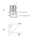
EGR制御弁52は、図2(A)に示したように、コイル52a、弁体52b、及び開口52c等を備えている。弁体52bと開口52cとで、絞りの程度が可変な絞り部が形成される。コイル52aは、電気制御装置60と接続されている。コイル52aは、電気制御装置60からの駆動信号(EGR制御弁開度指令値SEGRに応じて可変となるデューティ比を有する電圧信号)に応答して弁体52bの軸方向移動量(リフト量)を変更するデューティ制御式の電磁弁である。かかるEGR制御弁52は、図2(B)に示したように、EGR制御弁開度指令値SEGRに応じて開口52cの有効開口面積Aegrを変更し、エキゾーストマニホールド41からインテークマニホールド31に再循環される排ガス量(排気還流量、EGRガス流量)を調整するようになっている。
【0031】
なお、本装置はデューティ制御式電磁弁をEGR制御弁52として採用しているが、例えば、負圧を電気的に制御することで弁体のリフト量を変更する負圧駆動式弁、或いは、ステップモータ駆動式の制御弁等をEGR制御弁として採用することができる。
【0032】
EGRガス冷却装置53は、同装置の入口部から流入するとともに同装置の出口部から流出するEGRガスの通路を内部に形成している。また、EGRガス冷却装置53は、前記EGRガスの通路に露呈した冷却部を備えている。この冷却部内にはエンジン冷却水が冷媒として循環するようになっている。
【0033】
電気制御装置60は、互いにバスで接続されたCPU61、CPU61が実行するプログラム、テーブル(ルックアップテーブル、マップ)、及び定数等を予め記憶したROM62、CPU61が必要に応じてデータを一時的に格納するRAM63、電源が投入された状態でデータを格納するとともに同格納したデータを電源が遮断されている間も保持するバックアップRAM64、並びにADコンバータを含むインターフェース65等からなるマイクロコンピュータである。
【0034】
インターフェース65は、吸気管32に配置された熱線式エアフローメータ71、インタークーラー34とスロットル弁33との間の吸気通路に設けられた新気温センサ(吸気温センサ)72、スロットル弁33の下流であって排気還流管51が接続された部位よりも上流の吸気通路に配設された吸気圧センサ73、エンジン回転速度センサ74、水温センサ75及びアクセル開度センサ76と接続されていて、これらのセンサからの信号をCPU61に供給するようになっている。また、インターフェース65は、燃料噴射弁21、スロットル弁アクチュエータ33a、ターボチャージャ絞り弁35c、及びEGR制御弁52と接続されていて、CPU61の指示に応じてこれらに駆動信号を送出するようになっている。
【0035】
熱線式エアフローメータ71は、エアクリーナ36を介して吸気管32内に新たに吸入された大気(即ち、新気)の質量流量(単位時間当りの吸入空気量、単位時間あたりの新気量)を計測し、同新気の質量流量に応じた信号(新気流量)Gaを発生するようになっている。新気温センサ72は、エアクリーナ36を介して吸気管32内に吸入された新気の温度(即ち、新気温度)を検出し、同新気温度を表す信号Taを発生するようになっている。
【0036】
吸気圧センサ73は、吸気通路内の圧力(吸気圧、過給圧)を表す信号Pbを発生するようになっている。即ち、吸気圧センサ73は、排気還流管51が接続された吸気通路(インテークマニホールド31)におけるガスの圧力を吸気通路内ガス圧力として取得する吸気通路内ガス圧力取得手段を構成している。また、吸気圧センサ73は、EGR制御弁52の下流側におけるガスの圧力を下流側ガス圧力として取得する下流側ガス圧力取得手段でもある。
【0037】
エンジン回転速度センサ74は、エンジン10の回転速度を検出し、エンジン回転速度NEを表す信号を発生するとともに、各気筒の絶対クランク角度を検出し得るようになっている。水温センサ75は、エンジン10の冷却水温を検出し、同冷却水温を表す信号THWを発生するようになっている。アクセル開度センサ76は、アクセルペダルAPの操作量を検出し、アクセル開度(アクセル操作量)を表す信号Accpを発生するようになっている。
【0038】
次に、上記のように構成された内燃機関の制御装置の作動について説明する。電気制御装置60のCPU61は、図3に機能ブロック図で示された各値を計算するためのプログラムを所定時間の経過毎に繰り返し実行し、実EGR率Ractを計算するようになっている。以下、ブロック毎に説明を加える。なお、以下に述べる各値の幾つかは、図4に概念的に示されている。
【0039】
<実EGR率Ractの取得>
実EGR率Ractは、エンジン10のシリンダに吸入された単位時間あたりの実EGRガス流量Gegr(実際に排気還流管51から吸気通路内に流入するEGRガスの質量流量であって、以下、「EGRガス流量Gegr」と称呼する。)を同エンジン10に吸入された単位時間あたりの全ガス量Gcyl(実際の全ガス質量流量であって、以下、「全ガス流量Gcyl」とも称呼する。)で除した値(Ract=Gegr/Gcyl)である。EGRガス流量Gegrは、全ガス流量Gcylから、エンジン10に吸入された単位時間あたりの新気量Gaact(大気の質量、以下、「実新気流量Gaact」と云う。)を減じた量である。従って、CPU61は、ブロックB1に示したように、下記(1)式に基づいて実EGR率Ractを計算する。
【0040】
【数1】

<実新気流量Gaactの取得>
(1)式で用いられる実新気流量Gaactは、エアフローメータ71が計測した計測新気流量Gaよりも時間的に遅れて変化するから、同計測新気流量Gaに一次遅れ処理を施すことにより求められる値と略等しくなる。従って、CPU61は、計測新気流量Gaに対して一次遅れ処理を施すブロックB2に示した下記(2)式に基づいて実新気流量Gaactを計算する。αは0から1までの値を有する定数である。なお、Gaact(n)は今回の演算による実新気流量Gaact、Gaact(n−1)は所定時間前に実行された前回の演算による実新気流量Gaact、Ga(n)は今回の演算タイミングにおけるエアフローメータ71の出力に基く計測新気流量Gaである。
【0042】
【数2】
![]()
<全ガス流量Gcylの取得>
(1)式の計算を行うために更に必要となる全ガス流量Gcylは、気体の状態方程式からも推察されるように、スロットル弁33の下流の吸気管内の圧力(吸気圧)Pbとエンジン10のシリンダに吸入されるガスの温度(吸入ガス温度)Tboutとに応じた値となる。このエンジン10のシリンダに吸入されるガスの温度Tboutは、以下、「インテークマニホールド出口部ガス温度Tbout」と称呼する。
【0044】
実際には、全ガス流量Gcylはエンジン10の気筒内に残留するガス量の影響も受ける。従って、CPU61は、ブロックB3に示したように、下記(3)式で示した実験式に基づいて実EGR率Ractを計算する。(3)式において、a,bは実験により定められる適合定数であり、Tbaseはこれらの定数a,bを定めたときのインテークマニホールド出口部ガス温度(基準温度)である。また、(3)式で用いられる吸気圧(過給圧)Pbは、吸気圧センサ73から取得される。
【0045】
【数3】
<実ガス温度Tboutの取得>
(3)式の計算を行うためには、インテークマニホールド出口部ガス温度Tboutを取得する必要がある。CPU61は、ブロックB4に示したように、このインテークマニホールド出口部ガス温度Tboutを下記(4)式に従って計算する。
【0047】
【数4】
![]()
(4)式において、
Tbinは、図4に示したように、EGR制御弁52の出口側のインテークマニホールド31の内部、即ち、EGRガスと新気とが混合された部位(以下、単に「合流部」又は「インテークマニホールド入口部」と称呼する。)の混合ガス温度であり、以下「インテークマニホールド入口部ガス温度Tbin」と称呼する。
Twallimは、インテークマニホールド入口部から吸気弁までの間のインテークマニホールド31の壁温であり、以下、「インテークマニホールド壁温Twallim」と称呼する。
ηimは、インテークマニホールド入口部からインテークマニホールド出口部(吸気弁により開閉される部分)までの間のインテークマニホールド31における熱伝達率(冷却効率)であり、以下、「インテークマニホールド熱伝達率ηim」と称呼する。
【0049】
上記(4)式は、インテークマニホールド31の壁面とシリンダに吸入されるガスとの間での熱の授受、及び同インテークマニホールド31の壁面と外気(インテークマニホールド31の外側の空気の温度)Tairとの間での熱の授受を考慮した式であって、これらの熱の授受を右辺第2項(ηim・(Tbin−Twallim))で代表させた式である。この値(ηim・(Tbin−Twallim))は、インテークマニホールド31内を吸気(新気+EGRガス)が通過する際に、吸気の温度がどれだけ変化するかを示す変化温度対応値である。
【0050】
ガス(吸気)とガス流通管(インテークマニホールド31)との間の熱授受は、同ガスの入口部温度と同ガス流通管の壁温の差に強い相関(例えば、比例関係)がある。また、熱伝達率は、ガスとガス流通管壁との間の熱の授受、及びガス流通管壁と外部との間の熱の授受を適切に表すことが可能である。従って、上記構成によれば、前記熱授受を簡単で且つ精度良く推定することができ、前記変化温度対応値も精度良く推定することが可能となる。
【0051】
ところで、(4)式によりインテークマニホールド出口部ガス温度Tboutを取得するためには、同(4)式の右辺の各値(Tbin,Twallim,ηim)を取得しなければならない。以下、順に説明する。
【0052】
<インテークマニホールド入口部ガス温度Tbinの取得>
CPU61は、ブロックB5に示したように、インテークマニホールド入口部ガス温度Tbinをエネルギー保存則に基く下記(5)式に従って計算する。
【0053】
【数5】
![]()
(5)式の右辺における各値について図4を参照しながら説明する。
Gaactは先に説明した実新気流量であり、前記ブロックB2により(2)式に従って求められる。
Taは先に説明した新気温度であって新気温センサ72により検出される。
Cairは新気の比熱(新気ガス比熱)であって予め与えられる定数である。
【0055】
Gegrは先に説明したEGRガス流量であり、後述する方法により求められる。TegrはEGRガスと新気とが合流部にて混合する直前のEGRガス温度である。即ち、温度Tegrは、排気還流管51の前記吸気通路との接続部であるEGRガス出口部におけるEGRガスの温度であって、以下「排気還流管出口部EGRガス温度(EGR出口部EGRガス温度)Tegr」と称呼する。排気還流管出口部EGRガス温度Tegrは後述する方法により求められる。
CegrはEGRガスの比熱(EGRガス比熱)であって予め与えられる定数である。
【0056】
Gallは、EGRガスと新気とが混合したガスの総和量、即ち、実新気流量GaactとEGRガス流量Gegrとの和であって、以下、「インテークマニホールド入口部ガス流量Gall」と称呼する。
Caveは、EGRガスと新気とが混合したガスの比熱(混合ガス比熱)であり、予め与えられる定数である。
【0057】
(5)式によりインテークマニホールド入口部ガス温度Tbinを取得するためには、排気還流管出口部EGRガス温度Tegr、EGRガス流量Gegr、インテークマニホールド入口部ガス流量Gallを取得しなければならない。従って、以下、更に順を追って説明する。
【0058】
<排気還流管出口部EGRガス温度Tegrの取得>
CPU61は、ブロックB6に示したように、排気還流管出口部EGRガス温度Tegrを下記(6)式に従って計算する。ブロックB6は、出口部EGRガス温度推定手段を構成している。
【0059】
【数6】
![]()
(6)式において、
Texは、排気還流管51とエキゾーストマニホールド41との接合部近傍の同排気還流管51入口部におけるEGRガス温度(即ち、エキゾーストマニホールド41と排気還流管51との接合部近傍での排ガス温度)であり、以下、「排気還流管入口部ガス温度Tex(EGR通路入口部EGRガス温度Tex)」と称呼する。
ηegrは、EGRガス冷却装置53の冷却効率(熱伝達率)である。
THWは、エンジン10の冷却水温であるが、EGR冷却装置53の冷媒はエンジン冷却水であるから、冷却水温THWは冷媒の温度Treibaiと等しい。
【0061】
上記(6)式は、EGRガス冷却装置53(の冷却部)と同EGR冷却装置を通過するEGRガスとの間での熱の授受を考慮した式である。即ち、(6)式の右辺第2項(ηegr・(Tex‐THW))は、EGRガス冷却装置53内をEGRガスが通過する際に、EGRガスの温度がどれだけ変化するかを示す変化温度対応値である。
【0062】
実際には、EGRガスは、排気還流管入口部から流入して排気還流管出口部に到達するまでの間に、排気還流管51の壁面との間で熱の授受を行う。しかしながら、EGRガスと排気還流管51の壁面との間の熱交換量は、EGRガスとEGRガス冷却装置53との間の熱交換量に比べて極めて小さい。従って、(6)式の右辺第2項(ηegr・(Tex‐THW))は、EGRガスが排気還流管入口部から流入して排気還流管出口部に到達するまでの間に、同EGRガスの温度がどれだけ変化するかを示す値と実質的に等しい。
【0063】
ところで、(6)式により排気還流管出口部EGRガス温度Tegrを取得するためには、上記排気還流管入口部EGRガス温度Tex、及びEGR冷却装置の冷却効率ηegrを取得しなければならない。以下、順に説明する。
【0064】
<排気還流管入口部のEGRガス温度Texの取得>
CPU61は、ブロックB8及びブロックB9示したように、排気還流管入口部のEGRガス温度Tex(排ガス温度Tex)を下記(7)式に従って計算する。ブロックB8及びブロックB9は、EGRガス温度取得手段を構成している。
【0065】
【数7】
(7)式において、
単位時間あたりの燃料噴射量Gfは、図5のブロックBP3に示したように、指令燃料噴射量qfin及びエンジン回転速度NEに基いて求められる。例えば、Gf=kGf・qfin・NE( kGfは定数)である。
実新気流量Gaactは、上述したブロックB2により(2)式に基いて求められる。
過給圧Pbは、吸気圧Pbであり、吸気圧センサ73から取得される。
エキゾーストマニホールド内ガス圧力Pex(エキゾーストマニホールド41が構成する排気通路と排気還流管51との接続部であるEGRガス入口部におけるEGRガスの圧力)は、後述する手法により求められる。
【0067】
上記(7)式は、「排気還流管入口部EGRガス温度Texは、シリンダ内へ投入されるエネルギー(発熱量)と、同シリンダ内で発生した熱のガスへの伝達に大きく依存する。」という知見に基いている。シリンダ内へ投入されるエネルギーは燃料噴射量Gfに強い相関がある。また、シリンダ内で発生した熱のガスへの伝達は、実新気流量Gaact(実新気流量Gaactは発熱に寄与しない代わりに、排ガス温度を低下させるように機能する。)、又は、ガス比熱に関連した値である等量比Φに強い相関がある。そこで、(7)式では変数XTexに上記したような値を選択している。
【0068】
なお、変数Xtexのひとつに使用されている値(過給圧Pb/エキゾーストマニホールド内ガス圧力Pex)は、エキゾーストマニホールド41内における排ガスの通過のし易さ(留まり易さ)を表している。排ガスがエキゾーストマニホールド41内に留まるほど、同排ガスとエキゾーストマニホールド41外部との間でより多くの熱が伝達される。従って、(過給圧Pb/エキゾーストマニホールド内ガス圧力Pex)をパラメータとして導入することで、排気還流管入口部EGRガス温度Texの推定精度が高くなる。また、過給圧PbはEGRガス量と相関があり、且つ、EGRガス量が多ければ燃焼開始時の温度が高くなって排ガス温度Tex(排気還流管入口部EGRガス温度Tex)も高くなるので、過給圧Pbをパラメータとして考慮することは、この点においても同排ガス温度Texの精度向上に寄与する。
【0069】
(7)式の関数fTexと定数aはエンジンの機種毎に決定される。以下は、関数fTexと定数aを決定する手順の一例である。
(Step1) 関数fTexと定数aを決定すべきエンジンの運転条件を変更し、各エンジン状態量(Gf, Gaact, Pb, Pex, Tex)を測定する。
(Step2) 測定結果に基いて、変数XTexとEGRガス温度Texの実測値との相関が高くなるように定数aを決定する。なお、変数XTexに等量比Φを含む値を用いた場合には、定数aの値の調整(決定)は省略される。
(Step3) 決定された定数aで決る変数XTexとEGRガス温度Texの実測値とに基いて、関数fTexを決定する。
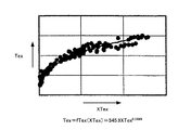
図8は、変数XTexとしてGf・Φ・(Pb/Pex)を選択した場合の同変数XTexと実測された排気還流管入口部EGRガス温度Texとの関係の一例を示している。この場合、関数fTexは、Tex=fTex(XTex)=545.9・XTex0.3489となった。
【0070】
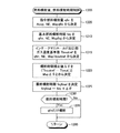
<エキゾーストマニホールド内ガス圧力Pexの取得>
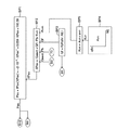
上記(7)式の変数XTexとしてエキゾーストマニホールド内ガス圧力Pexを含む変数を使用する場合等において、同エキゾーストマニホールド内ガス圧力Pexを求める必要がある。CPU61は、機能ブロック図である図5に示したように、下記(8)式に従ってエキゾーストマニホールド内ガス圧力Pexを算出する。なお、エキゾーストマニホールド内ガス圧力(排気還流管入口部EGRガス圧力)Pexは、エキゾーストマニホールド41が構成する排気通路と排気還流管51との接続部であるEGRガス入口部におけるEGRガスの圧力Pexである。また、図5に示した機能ブロックは、排気通路における前記EGRガスの圧力を取得する排気還流管入口部EGRガス圧力取得手段(EGRガス入口部EGRガス圧力取得、排気圧力取得手段)、或いは、EGR制御弁52の上流側におけるガスの圧力を上流側ガス圧力として取得する上流側ガス圧力取得手段を構成している。
【0071】
【数8】
(8)式において、
燃料噴射量Gfは、図5のブロックBP3に示したように、指令燃料噴射量qfin及びエンジン回転速度NEに基いて求められる。
実新気流量Gaactは、上述したブロックB2により(2)式に従って求められる。過給圧Pbは、吸気圧Pbであり、吸気圧センサ73から取得される。
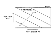
可変容量ターボチャージャ開度Avnは、図5のブロックBP4内に示したように、指令燃料噴射量qfin及びエンジン回転速度NEを引数とするテーブルにより求める値である。CPU61は、ターボチャージャ絞り弁35cの開度がこの値AVnに基いた値となるように、同ターボチャージャ絞り弁35cに対して駆動信号を供給する。また、可変容量ターボチャージャ開度Avnは、ブロックBP5にて定数avnが加えられ、上記(8)式の可変容量ターボチャージャ絞り係数Kvnに変換される。なお、後述するように、目標過給圧を設定して実際の過給圧が同目標過給圧となるように値AVnを決定してもよい。
【0073】
上記(8)式は、「エキゾーストマニホールド内ガス圧力Pexは、シリンダ内に流入するガス量(Gaact+Gf)、可変容量ターボチャージャ絞り弁35cの開度Avn、及びターボチャージャ35のタービン35bの抵抗を表す過給圧に極めて強い相関を有する。」という知見に基いている。
【0074】
(8)式の関数fPexと定数avnはエンジンの機種毎に決定される。以下は、関数fPexと定数avnを決定する手順の一例である。
(Step1) 関数fPexと定数avnを決定すべきエンジンの運転条件を変更し、各エンジン状態量(Gf, Gaact, Pb, Avn, Pex)を測定する。
(Step2) 測定結果に基いて、変数XPexとエキゾーストマニホールド内ガス圧力Pexとの相関が高くなるように定数avnを決定する。
(Step3) 決定された定数avnで決る変数XPexとエキゾーストマニホールド内ガス圧力Pexの実測値とに基いて、関数fPexを決定する。
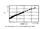
図9は、このようにして関数fPexを決定する際に使用した実測値の一例を示している。この例の場合、関数fPexは下記の(9)式のようになった。このように、本実施形態は、排気圧力センサを用いることなく排気圧力Pexを求めることができ、装置のコストを低下させることができる。
【0075】
【数9】
以上により、(7)式の変数XTexを求めるための各値(Gf,Gaact,Pb,Pex)が求められて変数XTexが決定される。従って、CPU61は、(7)式に従って計算を行い、排気還流管入口部EGRガス温度Tex(排ガス温度Tex)を求める。一方、(6)式に従って排気還流管出口部EGRガス温度Tegrを求めるためには、更に、EGRガス冷却装置の冷却効率ηegrを取得しなければならない。
【0077】
<EGRガス冷却装置の冷却効率ηegrの取得>
CPU61は、図3のブロックB10に示したように、EGRガス冷却装置の冷却効率ηegrを下記(10)式に従って計算する。ブロックB10は、冷却装置の冷却効率取得手段(推定手段)を構成している。
【0078】
【数10】
![]()
(10)式に示したように、EGRガス冷却装置の冷却効率ηegrを求めるためには、排気還流管入口部EGRガス温度TexとEGRガス流量Gegrとが必要となる。排気還流管入口部EGRガス温度Texは、ブロックB8及びブロックB9により上記(7)式により求められる。EGRガス流量Gegrは、後述するブロックB12により求められる。
【0080】
なお、(10)式でのEGRガス流量Gegrは、EGRガス流量Gegrに対応した値(EGRガス流量対応値)であればよく、例えば、排気還流管51の所定箇所におけるEGRガス流速Vegrで置き換えることができる。EGR通路(排気還流管51とEGRガス冷却装置53の形成するEGR通路)の形状は既知であるから、EGRガス流速Vegrに基いてEGRガス流量Gegrを推定できるからである。EGRガス流速Vegrは、排気還流管51内に流速センサを配設し、同流速センサの出力から直接取得してもよい。
【0081】
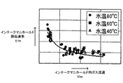
(10)式の関数fηegrはエンジンの機種毎に決定される。以下は、関数fηegrを決定する手順の一例である。
(Step1) 関数fηegrを決定すべきエンジンの運転条件を変更し、各エンジン状態量(Gegr, Tex, ηegr)を測定する。
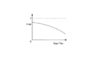
(Step2) 測定結果に基いて、図10に示したように、ηegrとGegr/Texとの関係をグラフ化する。
(Step3) step2のグラフに基いて、関数fηegrを決定する。
【0082】
図20に示したように、冷却効率ηegrとEGRガス流量Gegrとの関係は排気還流管入口部EGRガス温度Texが異なると変化する。これに対し、冷却効率ηegrと、EGRガス流量Gegrを排気還流管入口部EGRガス温度Texで除した値(Gegr/Tex)と、の関係は、図10に示したように、排気還流管入口部EGRガス温度Texに関わらず一義的に定まる。換言すると、冷却効率ηegrと排気還流管入口部EGRガス温度Texとは略反比例の関係にあることが実験的に判明したので、値(Gegr/Tex)を変数として冷却効率ηegrを求めることで、より簡便に関数fηegrを求めることができる。
【0083】
本装置は、上記関数fηegrを関数の形、又は、値(Gegr/Tex)とηegrとの組み合わせからなるデータをテーブル(一次元マップ)のテーブル値としてROM62内に格納していて、実際に得られた値(Gegr/Tex)と、格納されている関数又はテーブルとに基いて実際の冷却効率ηegrを求める。
【0084】
なお、電気制御装置60の計算能力及び/又は記憶容量に余裕がある場合、(Gegr,Tex,ηegr)をエンジンの運転状態を変化させながら実測し、その実測データをテーブルMapηegr(二次元マップ)としてROM62内に格納しておき、実際のEGRガス流量Gegr、実際の排気還流管入口部EGRガス温度Tex、及び前記格納したテーブルMapηegrとから実際の冷却効率ηegrを求めるようにしてもよい。或いは、ηegr=gTex(Gegr)なる関数gTexを排気還流管入口部EGRガス温度Tex毎に求めてROM内に格納しておき、実際の排気還流管入口部EGRガス温度Texに基いて記憶している複数の関数gTexの中から適切な関数gTexを選択し、その選択した関数gTexと実際のEGRガス流量Gegrとから冷却効率ηegrを求めてもよい。
【0085】
以上により、ブロックB6による(6)式に従う計算に必要な排気還流管入口部EGRガス温度Tex、EGRガス冷却装置の冷却効率ηegr、及び冷却水温THW(冷媒温度Treibai)が得られるので、同(6)式により排気還流管出口部EGRガス温度Tegrが求められる。この段階において、(5)式の計算を行うために更に求める必要がある変数は、EGRガス流量Gegr及びインテークマニホールド入口部ガス流量Gallである。以下、これらの求め方について説明する。
【0086】
<EGRガス流量Gegrの取得>
前述したEGR制御弁52は弁体52bと開口部52cとにより実質的に可変絞り部を形成し、同絞り部をEGRガスが通過する。このような絞り部をEGRガスが通過するとき、絞り部の下流のEGR流量Gegr0は下記の(11)式により求められる。(11)式は、絞り部での流速が音速を超えない範囲で成立する圧縮性流体に関する流量についての一般的な式である。EGR制御弁52において、絞り部52cでの流速は音速を超えないので、この(11)式が成立する。
【0087】
【数11】
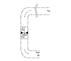
(11)式に使用される値を、図6を参照しながら説明する。
Pupは絞り部直前の上流側圧力である。
Pdnは絞り部直後の下流側圧力である。
ρaは、絞り部上流のEGRガスの密度である。
κは、EGRガスの比熱比である。
Aegrは、絞り部(EGR制御弁52の弁体52bと開口52cとで形成される絞り部)の有効開口面積である。
【0089】
実際には、CPU61は、上流側圧力Pupとしてエキゾーストマニホールド内ガス圧Pexを採用し、下流側圧力Pdnとして吸気圧(過給圧)Pbを採用し、EGR制御弁52の弁体52bと開口52cとで形成される絞り部直後の下流におけるEGRガス流量Gegr0を、下記(12)式に基いて求める。このEGRガス流量Gegr0を、便宜上、暫定EGRガス流量Gegr0と称呼する。
【0090】
【数12】
(12)式において、
エキゾーストマニホールド内ガス圧Pexは、図5のブロックBP1により上記(8)式(実際には、(9)式)に従って求められる。
過給圧Pbは、上記吸気圧センサ73から取得される。
EGRガスの比熱比κは予め与えられている。
有効開口面積Aegrは、CPU61からEGR制御弁52への指令値であるEGR制御弁開度指令値SEGRと、図2(B)に示したようなROM62内に格納されているテーブルMapAegrとに基いて求められる。この場合、EGR制御弁開度指令値SEGRに代えて、EGR制御弁52のリフト量を検出するセンサからの信号とテーブルMapAegrとに基づいて有効開口面積Aegrを用いてもよい。
上流側密度ρaは、エキゾーストマニホールド内ガス圧Pexと、排気還流管51入口部におけるEGRガス温度Texと、気体の状態方程式とに基いて求められる。実際には、EGRガスはEGR冷却装置53により冷却されて温度が低下するが、その際に圧力も低下するので、EGR制御弁に流入するEGRガスの密度と上記のようにして求める密度とは実質的に等しい密度となる。
【0092】
しかしながら、上記のようにして求められるEGRガス流量Gegr0は、EGRガスとEGR通路(排気還流管51及びEGRガス冷却装置53が形成する管)との間に生じる管摩擦の影響により、必ずしも精度が良好でない場合がある。
【0093】
即ち、上記(12)式は、上記(11)式において上流側圧力Pupとしてエキゾーストマニホールド内ガス圧Pexを採用し、下流側圧力Pdnとして吸気圧(過給圧)Pbを採用した結果、絞り(即ち、有効開口面積Aegr)の変化が絞り部を通過するガスの流量を支配的に決定するような状態においては有効である。しかし、それ以外の状態、即ち、管摩擦がガス流量を支配的に決定するようになる状態では、上記(12)式は必ずしも有効ではない。
【0094】
絞り(絞りの程度)又は管摩擦のどちらがガス流量を支配的に決定するかは、本来的には、絞りの有効開口面積Aegrとエキゾーストマニホールド内ガス圧Pexと吸気圧Pbの差圧dP(=Pex−Pb)との相対関係により定まる筈である。しかし、一般には、差圧dP(=Pex−Pb)が大きい場合、絞り部(絞りの程度)が同絞り部を通過するガスの流量を支配的に決定すると考えられる。これに対し、差圧dPが小さい場合、絞りの変化に代わり、上流側圧力Pup及び下流側圧力Pdnとしてエキゾーストマニホールド内ガス圧Pex及び吸気圧Pbをそれぞれ採用した結果として、管摩擦(排気還流管51の長さに応じる。)がガスの流量を支配的に決定すると考えられる。
【0095】
更に、上記(11)式において上流側圧力Pupとしてエキゾーストマニホールド内ガス圧Pexを採用し、下流側圧力Pdnとして吸気圧(過給圧)Pbを採用した結果、計算に使用される絞り部の上下差圧dPは、実際の絞り部の直前直後における上下差圧より大きくなる。このため、上下差圧dPが小さい領域では絞り部の直前直後における上下差圧は極めて小さく、絞りはガス流量の支配的要因とはならない。このようなことから、(12)式による暫定EGRガス量Gegr0は、実際にEGR制御弁52を通過するEGRガス量よりも大きめの値として計算されてしまう傾向にある。
【0096】
そこで、本装置は、「エキゾーストマニホールド内ガス圧Pexと吸気圧(過給圧)Pbの差圧dP(=Pex−Pb)」に応じて定まる補正係数(補正値)dPgainを導入し、この補正係数dpgainにより上記(12)により求められるEGRガス流量Gegr0を補正する。
【0097】
即ち、差圧dPが減少するほど上記管摩擦のEGRガス流量に及ぼす影響が大きくなるので、差圧dPの減少とともに「0」に近づき、差圧dPの増大とともに「1」に近づく補正係数dPgainを、上記(12)により求められるEGRガス流量Gegr0に乗じることにより、排気還流管出口部EGRガス流量Gegrを求める。
【0098】
具体的には、CPU61は、図7に示したブロックBG1により、差圧dPとROM62内に格納されている同ブロックBG1内に示したテーブルMapdPgainとに基いて補正係数(補正値)dPgainを求める。また、ブロックB12aにより、EGR制御弁開度指令値SEGRと図2(B)に示したROM62内に格納されているテーブルMapAegrとに基いて有効開口面積Aegrを求める。そして、図3のブロックB12により、上記(12)式及び下記(13)式に基いて排気還流管出口部EGRガス流量(実際にEGR制御弁52を通過するEGRガス流量)Gegrを求める。
【0099】
【数13】
なお、ブロックB12の上記(12)式を実行する部分は、圧縮性流体が絞り部を通過する場合の同圧縮性流体の絞り部通過流量を同絞り部直前の上流側における同圧縮性流体の圧力及び同絞り部直後の下流側における同圧縮性流体の圧力とに基いて表す一般式(上記(11)式)を用いて、前記EGR制御弁を通過するEGRガスの流量を暫定EGRガス流量Gegr0として推定する手段であり、同絞り部直前の上流側における同圧縮性流体の圧力として前記取得された上流側ガス圧力を採用するとともに、同絞り部の直後の下流側における同圧縮性流体の圧力として前記取得された下流側ガス圧力を採用することで同暫定EGRガス流量Gegr0を推定する暫定EGRガス流量推定手段を構成している。
【0101】
また、ブロックB12の補正係数(補正値)dPgainを求める部分、及び(13)式を実行して暫定EGRガス流量に補正係数dPgainを乗じて同暫定EGRガス量Gegr0を補正する部分は、同推定された暫定EGRガス流量Gegr0に含まれる排気還流管51とEGRガスとの間の管摩擦に起因する誤差を補正することにより排気還流管51から吸気通路に流入するEGRガスの流量Gegrを推定するEGRガス流量推定手段を構成している。
【0102】
<インテークマニホールド入口部ガス流量Gall>
インテークマニホールド入口部ガス流量Gallは、上述したように、実新気流量GaactとEGRガス流量Gegrとの和である。CPU61は、図3のブロックB13に示したように、インテークマニホールド入口部ガス流量Gallを下記(14)式に従って計算する。
【0103】
【数14】
![]()
(14)式における実新気流量GaactはブロックB2により上記(2)式に基いて求められる。EGRガス流量GegrはブロックB12により上記(12)及び(13)式に基いて求められる。
【0105】
以上により、上記(5)式に従う計算に必要な各値が求められるので、CPU61はブロックB5により同(5)式に基いてインテークマニホールド入口部ガス温度Tbinを求める。一方、この段階において、(4)式(ブロックB4)によりインテークマニホールド出口部ガス温度Tboutを求めるために必要な変数は、インテークマニホールド壁温Twallim、及びインテークマニホールド熱伝達率ηimである。これらは、次のようにして求められる。
【0106】
<インテークマニホールド壁温Twallimの取得>
インテークマニホールド壁温Twallimは、水温センサ75が検出する冷却水温THWと相関が強い。従って、CPU61は、ブロックB14により、冷却水温THWの増大とともに増大する関数f1Twallimを使用して下記(15)式に従ってインテークマニホールド壁温Twallimを計算する。なお、関数f1Twallimは、予め実験により求められ、ROM62内に格納されている。
【0107】
【数15】
![]()
<インテークマニホールド熱伝達率ηimの取得>
CPU61は、ブロックB15及びブロックB16に示したように、インテークマニホールド熱伝達率ηimを下記(16)式に従って計算する。
【0109】
【数16】
(16)式において、Vimはインテークマニホールド内ガス流速である。このインテークマニホールド内ガス流速Vimは、インテークマニホールド31の形状が既知であるから、上記(16)式に示したように、インテークマニホールド入口部ガス流量Gallに基いて求めることができる。インテークマニホールド入口部ガス流量Gallは、ブロックB13により上記(16)式に従って求められる。
【0111】
なお、インテークマニホールド内ガス流速Vimは、インテークマニホールド31に流速センサを配設し、同センサの出力から直接取得してもよい。一方、(16)式の関数fηimはインテークマニホールド内ガス流速Vimを変数としているが、これに代えて、インテークマニホールド入口部ガス流量Gallを変数としてもよい。
【0112】
上記(16)式は、「インテークマニホールド熱伝達率ηimは、インテークマニホールド31内のガス流速Vimに大きく影響を受ける。」という知見に基いている。なお、(16)式においては、冷却水温THWをも変数としてインテークマニホールド熱伝達率ηimを求めているが、冷却水温THWを省略して単にインテークマニホールド内ガス流速Vimの関数(ηim=fηim(Vim))、又はインテークマニホールド入口部ガス流量Gallの関数(ηim=fηim(Gall))としてインテークマニホールド熱伝達率ηimを求めて求めてもよい。
【0113】
関数fηimはエンジンの機種毎に異なるので、その都度実測値との比較に基いて決定する。あるエンジンに対する実測値の例を図11に示す。図11の例では、下記(17)式に示すように関数fηimが決定される。
【0114】
【数17】
以上により、上記(4)式に従う計算に必要な各値(Tbin,ηim,Twallim)が求められるので、CPU61はブロックB4により同(4)式に基いてインテークマニホールド出口部ガス温度Tboutを求める。従って、CPU61はブロックB3により(3)式に基いてエンジン10に吸入された単位時間あたりの全ガス流量Gcylを求め、その結果、ブロックB1により(1)式に基いて実EGR率Ractを求める。
【0116】
次に、このように取得される各値を用いたエンジン10の各種制御について説明する。
【0117】
<燃料噴射量及び燃料噴射時期制御>
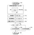
CPU61は、図12にフローチャートにより示した燃料噴射量及び燃料噴射時期を制御するためのルーチンを所定時間の経過毎に繰り返し実行するようになっている。従って、所定のタイミングになると、CPU61はステップ1200から処理を開始し、ステップ1205に進んでアクセル開度Accp、エンジン回転速度NE、及び図13に示したテーブル(マップ)Mapqfinから指令燃料噴射量qfinを求める。テーブルMapqfinは、アクセル開度Accp及びエンジン回転速度NEと指令燃料噴射量qfinとの関係を規定するテーブルであり、ROM62内に格納されている。
【0118】
次いで、CPU61はステップ1210に進み、指令燃料噴射量qfin、エンジン回転速度NE、及び図14に示したテーブルMapfinjから基本燃料噴射時期finjを決定する。テーブルMapfinjは、指令燃料噴射量qfin及びエンジン回転速度NEと基本燃料噴射時期finjとの関係を規定するテーブルであり、ROM62内に格納されている。
【0119】
その後、CPU61はステップ1215に進んで、インテークマニホールド出口部ガス温度基準値Tboutrefを、指令燃料噴射量qfi、エンジン回転速度NE、及び図15に示したテーブルMapTboutrefから決定する。テーブルMapTboutrefは、指令燃料噴射量qfin及びエンジン回転速度NEとインテークマニホールド出口部ガス温度基準値Tboutrefとの関係を規定するテーブルであり、ROM62内に格納されている。このインテークマニホールド出口部ガス温度基準値Tboutrefは、指令燃料噴射量qfinとエンジン回転速度NEとの組み合わせに対して図14に示した基本噴射時期finjを決定したときのインテークマニホールド出口部ガス温度Tboutである。
【0120】
次いで、CPU61は、ステップ1220に進んで、噴射時期補正値Δθを、前記決定したインテークマニホールド出口部ガス温度基準値Tboutrefと図3に示したブロックB4により求められている実際のインテークマニホールド出口部ガス温Tboutとの差(Tboutref−Tbout)と図16に示したテーブルMapΔθとから決定する。テーブルMapΔθは、差(Tboutref−Tbout)と噴射時期補正値Δθとの関係を規定するテーブルであり、ROM62内に格納されている。
【0121】
次いで、CPU61はステップ1225に進み、基本噴射時期finjを噴射時期補正値Δθで補正して最終噴射時期finjfinalを決定する。このように、上記ステップ1215〜1225により、インテークマニホールド出口部ガス温Tboutに応じて噴射時期が補正されることになる。この場合、図16から明らかなように、インテークマニホールド出口部ガス温度Tboutがインテークマニホールド出口部ガス温度基準値Tboutrefより高くなるほど噴射時期補正値Δθが負の大きな値となって最終噴射時期finjfinalが遅角側となり、インテークマニホールド出口部ガス温度Tboutがインテークマニホールド出口部ガス温度基準値Tboutrefより低くなるほど噴射時期補正値Δθは正の大きな値となって最終噴射時期finjfinalが進角側に移行される。
【0122】
このように噴射時期を決定するのは、インテークマニホールド出口部ガス温度Tboutが高いときは同温度Tboutが低いときよりも燃料の着火性が良好であるから、燃料噴射時期を遅角しても着火性に問題がなく、NOxの排出量を低減することができるからである。一方、インテークマニホールド出口部ガス温度Tboutが低いときは燃料の着火性が悪化するから、燃料噴射時期を進角して着火性を確保するためである。これにより、エンジン10の出力性能の向上及びNOx排出量の低減が達成され得る。
【0123】
そして、CPU61は、続くステップ1230にて現時点が上記決定された最終燃料噴射時期finjfinalと一致しているか否かを判定し、一致している場合はステップ1235に進んで上記決定された指令燃料噴射量qfinの燃料を噴射時期が到来しているシリンダの燃料噴射弁21から噴射し、ステップ1295に進んで本ルーチンを一旦終了する。また、ステップ1230にて「No」と判定される場合、直接ステップ1295に進んで本ルーチンを一旦終了する。以上により、燃料噴射量と燃料噴射時期の制御が達成される。
【0124】
<EGR制御>
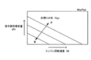
次に、EGR率制御について説明する。CPU61は、図17にフローチャートにより示したEGR率を制御するためのルーチンを所定時間の経過毎に繰り返し実行するようになっている。従って、所定のタイミングになると、CPU61はステップ1700から処理を開始し、ステップ1705に進んで、その時点の指令燃料噴射量qfin、その時点のエンジン回転速度NE、及び同ステップ内に示したテーブルMapO2tgtから目標吸気酸素濃度O2tgtを決定する。テーブルMapO2tgtは、指令燃料噴射量qfin及びエンジン回転速度NEと、目標吸気酸素濃度O2tgtとの関係を規定するテーブルであり、ROM62内に格納されている。
【0125】
次に、CPU61はステップ1710にて指令燃料噴射量qfin及びエンジン回転速度NEから単位時間当りの供給燃料量Qを求め、続くステップ1715にて空気過剰率λを同ステップ中に記載した式(λ=kλ・Gaact/Q)により求める。kλは定数である。次いで、CPU61はステップ1720にて目標EGR率Rtgtを、上記ステップ1705にて決定した目標吸気酸素濃度O2tgt、上記ステップ1720にて求めた空気過剰率λ、及び同ステップ1720内に記載した式(Rtgt=λ・(p・O2tgt+q)、 p及びqは定数)に基いて求める。なお、吸気酸素濃度、EGR率、及び空気過剰率との関係は、例えば、特開平10−141147に詳細に開示されている。
【0126】
次いで、CPU61はステップ1725にて、図3に示したブロックB1にて求めた実EGR率Ractが前記ステップ1720にて求めた目標EGR率Rtgtより大きいか否かを判定し、同ステップ1720にて「Yes」と判定される場合、ステップ1730に進んでEGR制御弁52を所定の開度だけ閉じ、EGR率を減少させてステップ1795に進んで本ルーチンを一旦終了する。他方、ステップ1725にて「No」と判定される場合、CPU61はステップ1735に進んでEGR制御弁52を所定の開度だけ開き、EGR率を増大させてステップ1795に進む。以上により、実際の酸素吸気濃度が目標酸素吸気濃度O2tgtに一致するようにEGR率が制御され、NOxの排出量低減及びスモークの低減が達成される。
【0127】
なお、上述した図17に示したルーチンによるEGR率制御においては、目標酸素吸気濃度O2tgtを求め、この目標酸素吸気濃度O2tgtを目標EGR率Rtgtに変換することによりEGR率を制御していたが、指令燃料噴射量qfin及びエンジン回転速度NEと目標EGR率Rtgtとの関係を規定した図18に示したテーブルMapRtgt、実際の指令燃料噴射量qfin、及び実際のエンジン回転速度NEから直接目標EGR率Rtgtを求めて、実際のEGR率Ractが同目標EGR率Rtgtと一致するようにEGR制御弁52の開度を制御してもよい。
【0128】
<過給圧制御>
次に、過給圧制御について説明する。CPU61は、図示しない過給圧制御のためのルーチンを所定時間の経過毎に繰り返し実行し、同所定時間の経過毎に、その時点の指令燃料噴射量qfin、その時点のエンジン回転速度NE、及び図19示したテーブルMapPbtgtから目標過給圧Pbtgtを決定する。テーブルMapPbtgtは、指令燃料噴射量qfin及びエンジン回転速度NEと、目標過給圧Pbtgtとの関係を規定するテーブルであり、ROM62内に格納されている。
【0129】
そして、CPU61は、決定された目標過給圧Pbtgtと吸気圧センサ73から取得される実際の過給圧Pbとを比較し、同目標過給圧Pbtgtと同実際の過給圧Pbとが一致するようにターボチャージャ絞り弁35cの開度を制御する。このようにして、過給圧制御が実行される。
【0130】
以上、説明したように、本発明による内燃機関の制御装置の実施形態によれば、EGRガス冷却装置53の冷却効率が、排気還流管入口部EGRガス温度とEGRガス流量対応値とに基いて求められるので、結果として、排気還流管出口部EGRガス温度の推定精度が向上する。また、新気とEGRガスとの混合ガス(吸気)とインテークマニホールド31との間の熱の授受が考慮されてインテークマニホールド出口部ガス温度Tboutが推定されるので、同温度Tboutの推定精度も向上し、その結果、EGR率を精度良く推定することができる。
【0131】
また、上記実施形態によれば、絞り部を通過する圧縮性流体の流量に関する一般式により求めた暫定EGRガス流量Gegr0に含まれている管摩擦に起因する誤差が、補正値dPgainにより補正される。この結果、本装置は、取得される絞り部上流側のガスの圧力(Pex)と取得される絞り部下流側のガスの圧力(Pb)との差が小さくなって、絞りの程度よりも管摩擦がEGRガス量を支配的に決定する傾向が強くなる場合においても、吸気通路に流入する(EGR制御弁52を通過する)EGRガス量Gegrを精度良く推定することが可能となる。
【0132】
なお、本発明は上記実施形態に限定されることはなく、本発明の範囲内において種々の変形例を採用することができる。例えば、エキゾーストマニホールド内ガス圧力Pexは、エキゾーストマニホールド41と排気還流管51との接続部近傍に排気圧力センサ(排気還流管入口部EGRガス圧力取得手段)を配設し、この排気圧力センサの出力値に基いて求めるように構成してもよい。
【0133】
また、上記補正係数dPgainは、有効開口面積Aegrと差圧dPとの両者に基いて求めるように構成してもよい。即ち、暫定EGR流量Gegr0を有効開口面積Aegrと差圧dPとに応じて補正するように構成してもよい。
【図面の簡単な説明】
【図1】本発明の第1実施形態に係る内燃機関の制御装置を4気筒内燃機関(ディーゼル機関)に適用したシステム全体の概略構成図である。
【図2】図2(A)は図1に示したEGR制御弁の概略断面図、図2(B)は、そのEGR制御弁に付与される駆動信号と有効開口面積の関係を示したグラフ(テーブル)である。
【図3】図1に示したCPUが実行するプログラムの内容を表した機能ブロック図である。
【図4】図1に示したCPUが計算する値を説明するための図である。
【図5】図1に示したCPUが実行するプログラムの内容を表した機能ブロック図である。
【図6】絞り部におけるガス流量の一般式を説明するための図である。
【図7】図1に示したCPUが実行するプログラムの内容を表した機能ブロック図である。
【図8】排気還流管入口部EGRガス温度Texを求めるための関数fTexを決定する際に使用した実測値の一例を示すグラフである。
【図9】エキゾーストマニホールド内ガス圧力Pexを求めるための関数fPexを決定する際に使用した実測値の一例を示すグラフである。
【図10】EGRガス冷却装置の冷却効率ηegrとEGRガス流量Gegrを排気還流管入口部EGRガス温度Texで除した値(Gegr/Tex)との関係を示すグラフである。
【図11】インテークマニホールド熱伝達率ηimを求めるための関数fηimを決定する際に使用した実測値の一例を示すグラフである。
【図12】図1に示したCPUが実行するプログラムを示したフローチャートである。
【図13】図1に示したCPUが図12に示したプログラムを実行する際に参照する指令燃料噴射量を決定するためのテーブルである。
【図14】図1に示したCPUが図12に示したプログラムを実行する際に参照する基本噴射時期を決定するためのテーブルである。
【図15】図1に示したCPUが図12に示したプログラムを実行する際に参照するインテークマニホールド出口部ガス温度基準値を決定するためのテーブルである。
【図16】図1に示したCPUが図12に示したプログラムを実行する際に参照する噴射時期補正値を決定するためのテーブルである。
【図17】図1に示したCPUが実行するプログラムを示したフローチャートである。
【図18】第1実施形態の変形例に係る内燃機関の制御装置のCPUが目標EGR率を決定する際に参照するテーブルである。
【図19】図1に示したCPUが目標過給圧を決定するために参照するテーブルである。
【図20】冷却効率ηegrとEGRガス流量Gegrとの関係を、排気還流管入口部EGRガス温度Texをパラメータとして示しグラフである。
【符号の説明】
21…燃料噴射弁、31…インテークマニホールド、32…吸気管、33…スロットル弁、35…ターボチャージャ、41…エキゾーストマニホールド、42…排気管、43…DPNR、50…EGR装置、51…排気還流管、52…EGR制御弁、60…電気制御装置。[0001]
TECHNICAL FIELD OF THE INVENTION
The present invention relates to an EGR gas flow rate estimation device for an internal combustion engine that estimates the flow rate of EGR gas flowing from an exhaust gas recirculation pipe of an internal combustion engine into an intake passage.
[0002]
[Prior art]
BACKGROUND ART Conventionally, an EGR device that circulates a part of exhaust gas of an internal combustion engine to an intake passage via an exhaust gas recirculation pipe in order to reduce an amount of nitrogen oxides (NOx) discharged from the internal combustion engine has been widely known. . The EGR device is applied to both a spark ignition type internal combustion engine and a diesel engine. In this case, the EGR gas flow rate is controlled by making the opening degree (effective opening cross-sectional area) of the EGR control valve interposed in the exhaust gas recirculation pipe variable.
[0003]
Such an EGR device estimates an EGR gas flow rate flowing into the intake passage and measures a fresh air flow rate flowing into the intake passage, and based on the estimated EGR gas flow rate and the measured fresh air flow rate, An EGR rate, which is a ratio of the EGR gas flow rate to the flow rate of all gases sucked into the engine (that is, a mixed gas of fresh air and EGR gas, also referred to as “intake” hereinafter), is obtained. The EGR gas flow rate is controlled based on the EGR rate. Therefore, in engine control such as control of the EGR gas flow rate, it is extremely important to accurately estimate the EGR gas flow rate flowing into the intake passage. Therefore, the conventional device estimates the EGR gas flow rate based on the differential pressure across the EGR control valve and the opening degree of the EGR control valve (for example, see Patent Document 1).
[0004]
[Patent Document 1]
JP 2001-280202 A (
[0005] and page 4)
[0006]
[Problems to be solved by the invention]
The above-described conventional apparatus is configured to provide a difference between a pressure detected by a boost sensor (intake pressure sensor) disposed in an intake passage and a pressure detected by a pressure sensor disposed at an appropriate position on the upstream side of the EGR control valve. The EGR gas flow rate is estimated by using the pressure as the front-back differential pressure. However, the differential pressure immediately before and after the EGR control valve and the differential pressure used for estimating the EGR gas amount may be largely different due to pipe friction generated between the EGR gas and the exhaust gas recirculation pipe. In this case, there is a problem that the EGR gas flow rate cannot be accurately estimated.
[0007]
In particular, when the compressible fluid passes through the throttle section (EGR control valve), the flow rate of the compressible fluid passing through the throttle section is determined by the pressure of the compressible fluid on the upstream side immediately before the throttle section and the downstream side immediately after the throttle section. The flow rate of the EGR gas passing through the EGR control valve (accordingly, the flow rate of the EGR gas flowing into the intake passage, ), There is a problem that the estimation error of the EGR flow rate due to the influence of the pipe friction increases, and the estimation accuracy of the EGR gas flow rate deteriorates.
[0008]
The present invention has been made to address such a problem, and an object of the present invention is to accurately determine the flow rate of EGR gas flowing into an intake passage via an EGR control valve by considering the above-mentioned pipe friction. An object of the present invention is to provide an EGR gas flow rate estimating device for an internal combustion engine that can be estimated.
[0009]
[Overview of the present invention]
An EGR gas flow rate estimation device for an internal combustion engine according to the present invention includes an exhaust gas recirculation pipe connected to an exhaust passage and an intake passage of an internal combustion engine, and a flow rate of EGR gas interposed in the exhaust gas recirculation tube and flowing through the exhaust gas recirculation tube. An EGR gas flow rate estimating device for an internal combustion engine, comprising: an EGR control valve having a restrictor for controlling the EGR gas flow rate. An upstream gas that obtains the pressure of the EGR gas upstream of the EGR control valve as an upstream gas pressure. Pressure obtaining means, downstream gas pressure obtaining means for obtaining the pressure of gas downstream of the EGR control valve as downstream gas pressure, and a throttle portion of the compressible fluid when the compressible fluid passes through the throttle portion. The EGR control valve using a general formula that expresses the flow rate based on the pressure of the same compressible fluid on the upstream side immediately before the throttle portion and the pressure of the same compressible fluid on the downstream side immediately after the throttle portion. Means for estimating the flow rate of the passing EGR gas as a provisional EGR gas flow rate, employing the acquired upstream gas pressure as the pressure of the compressible fluid on the upstream side immediately before the throttle section, and immediately after the throttle section. A provisional EGR gas flow rate estimating means for estimating the provisional EGR gas flow rate by employing the acquired downstream gas pressure as the pressure of the compressible fluid on the downstream side of the compressible fluid, and including the provisional EGR gas flow rate in the estimated provisional EGR gas flow rate EGR gas flow rate estimating means for estimating the flow rate of EGR gas flowing into the intake passage from the exhaust gas recirculation pipe by correcting an error caused by pipe friction between the exhaust gas recirculation pipe and the EGR gas. Have.
[0010]
According to the general formula representing the flow rate of the compressible fluid passing through the throttle section when the compressible fluid passes through the throttle section, the pressure of the compressible fluid on the upstream side immediately before the throttle section and the downstream side immediately after the throttle section By using the pressure of the same compressible fluid in the above, the flow rate passing through the throttle portion can be accurately obtained.
[0011]
Therefore, the present device acquires the gas pressure (eg, exhaust pressure) at an appropriate position (eg, exhaust passage) on the upstream side of the throttle section formed by the EGR control valve, and calculates the acquired gas pressure by the general formula. Is adopted as the pressure of the same compressible fluid on the upstream side immediately before the throttle portion in (1). Further, the present apparatus obtains the gas pressure at an appropriate position downstream of the throttle unit (for example, an intake passage), and converts the obtained gas pressure to the same compression in the general formula on the downstream side immediately after the throttle unit. The tentative EGR gas flow rate is determined by adopting the pressure as the ionic fluid pressure.
[0012]
The present device corrects an error caused by pipe friction between the exhaust gas recirculation pipe and the EGR gas included in the estimated provisional EGR gas flow rate, and reduces a flow rate of the EGR gas flowing into the intake passage. presume.
[0013]
Based on the pressure of the same compressible fluid on the upstream side immediately before the throttle portion and the pressure of the same compressible fluid on the downstream side immediately after the throttle portion, the general formula can accurately determine the gas amount passing through the throttle portion. It is possible to estimate. However, in the present invention, the obtained upstream gas pressure is adopted as the pressure of the same compressible fluid on the upstream side immediately before the throttle used in the general formula, and immediately after the throttle used in the general formula. The obtained downstream gas pressure is adopted as the pressure of the same compressive fluid downstream of.
[0014]
Therefore, the provisional EGR gas flow rate obtained by the apparatus of the present invention includes an error caused by pipe friction. Therefore, as described above, the apparatus according to the present invention includes means for correcting the error. As a result, in the present apparatus, the difference between the acquired gas pressure on the upstream side of the throttle unit and the acquired pressure of the gas on the downstream side of the throttle unit becomes smaller, and the pipe friction reduces the EGR gas amount more than the degree of the throttle. Even when the tendency to be dominantly determined becomes strong (that is, when the amount of change in the EGR gas flow rate with respect to the change in the throttle becomes small), it is possible to accurately estimate the amount of EGR gas flowing into the intake passage. Become.
[0015]
In this case, the upstream gas pressure acquisition unit is configured to acquire the pressure of gas in the exhaust passage to which the exhaust gas recirculation pipe is connected as the upstream gas pressure, and the downstream gas pressure acquisition unit includes: It is preferable that the pressure of the gas in the intake passage to which the exhaust gas recirculation pipe is connected be obtained as the downstream gas pressure.
[0016]
According to this, for example, the upstream gas pressure and the downstream pressure can be obtained from the outputs of the exhaust pressure sensor and the intake pressure sensor. Further, since the exhaust pressure is a value that can be estimated with high accuracy by performing a predetermined calculation and relatively easily (for example, compared with the pressure in the exhaust gas recirculation pipe), the exhaust pressure sensor can be omitted. It becomes. According to the present invention, the EGR gas flow rate is accurately estimated even when each pressure is obtained as described above.
[0017]
In this case, the EGR gas flow rate estimating means calculates a correction value based on the differential pressure between the obtained upstream gas pressure and the obtained downstream gas pressure, and calculates the provisional EGR gas flow rate based on the correction value. Is preferably configured to correct an error included in the above.
[0018]
Generally, the differential pressure dP between the acquired upstream gas pressure and the acquired downstream gas pressure has a strong correlation with the degree of influence of pipe friction on the gas flow rate. That is, when the differential pressure dP is large, it is considered that the degree of throttling predominantly determines the flow rate of the gas passing through the throttling portion. On the other hand, when the differential pressure dP is small, it is considered that the pipe friction predominantly determines the gas flow rate instead of the degree of restriction. Therefore, according to the above configuration, since the correction value is properly obtained, the estimation accuracy of the EGR gas flow rate is improved.
[0019]
In a more specific aspect of the present invention, the provisional gas flow rate estimating means is configured such that the acquired upstream gas pressure is Pex, the acquired downstream gas pressure is Pb, the effective opening area of the throttle unit is Aegr, When the density of the EGR gas on the upstream side immediately before the throttle section is ρa and the specific heat ratio of the EGR gas is κ,
Gegr0 = Aegr · (2 · Pex · ρa)1/2・ Φ
Φ = (((κ / (κ-1))) ((Pb / Pex)2 / κ-(Pb / Pex)(1 + 1 / κ )))1/2
The provisional EGR gas flow rate Gegr0 is configured to be estimated based on the general formula, and the EGR gas flow rate estimation means increases the differential pressure (Pex−Pb) so that the correction value increases toward 1 as the differential pressure (Pex−Pb) increases. A value dPgain is obtained, and the flow rate Gegr of the EGR gas flowing into the intake passage is estimated by multiplying the provisional EGR gas flow rate Gegr0 by the correction value dPgain.
[0020]
BEST MODE FOR CARRYING OUT THE INVENTION
Hereinafter, one embodiment of a control device for an internal combustion engine (diesel engine) including an EGR gas flow rate estimation device for an internal combustion engine and an EGR control device according to the present invention will be described with reference to the drawings.
[0021]
FIG. 1 shows a schematic configuration of an entire system in which a control device for an internal combustion engine according to the present invention is applied to a four-cylinder internal combustion engine (diesel engine) 10. The system includes an
[0022]
A
[0023]
The
[0024]
The
[0025]
The
[0026]
The
[0027]
The
[0028]
The portion of the exhaust
[0029]
In addition, when the
[0030]
As shown in FIG. 2A, the
[0031]
Although the present apparatus employs a duty control type solenoid valve as the
[0032]
The EGR
[0033]
The
[0034]
The
[0035]
The hot-wire
[0036]
The
[0037]
The engine
[0038]
Next, the operation of the control device for an internal combustion engine configured as described above will be described. The
[0039]
<Acquisition of actual EGR rate Ract>
The actual EGR rate Ract is an actual EGR gas flow rate Gegr (actually, a mass flow rate of the EGR gas flowing into the intake passage from the exhaust gas recirculation pipe 51) per unit time sucked into the cylinder of the
[0040]
(Equation 1)
<Acquisition of actual fresh air flow rate Gaact>
Since the actual fresh air flow rate Gaact used in the equation (1) changes with a time delay later than the measured fresh air flow rate Ga measured by the
[0042]
(Equation 2)
![]()
<Acquisition of total gas flow rate Gcyl>
The total gas flow rate Gcyl further required for calculating the equation (1) is determined by the pressure (intake pressure) Pb in the intake pipe downstream of the
[0044]
Actually, the total gas flow rate Gcyl is also affected by the amount of gas remaining in the cylinder of the
[0045]
(Equation 3)
<Acquisition of actual gas temperature Tbout>
In order to calculate the equation (3), it is necessary to obtain the intake manifold outlet gas temperature Tbout. As shown in block B4, the
[0047]
(Equation 4)
![]()
In equation (4),
As shown in FIG. 4, Tbin is the inside of the
Twallim is the wall temperature of the
ηim is the heat transfer coefficient (cooling efficiency) in the
[0049]
The above equation (4) indicates that heat is transferred between the wall surface of the
[0050]
Heat transfer between the gas (intake) and the gas flow pipe (intake manifold 31) has a strong correlation (for example, a proportional relationship) between the difference between the inlet temperature of the gas and the wall temperature of the gas flow pipe. Further, the heat transfer coefficient can appropriately represent the transfer of heat between the gas and the gas flow pipe wall and the transfer of heat between the gas flow pipe wall and the outside. Therefore, according to the above configuration, the heat transfer can be easily and accurately estimated, and the changed temperature corresponding value can also be accurately estimated.
[0051]
By the way, in order to obtain the intake manifold outlet gas temperature Tbout by the equation (4), each value (Tbin, Twallim, ηim) on the right side of the equation (4) must be obtained. Hereinafter, description will be made in order.
[0052]
<Acquisition of intake manifold inlet gas temperature Tbin>
As shown in block B5, the
[0053]
(Equation 5)
![]()
Each value on the right side of the equation (5) will be described with reference to FIG.
Gaact is the actual fresh air flow rate described above, and is obtained by the block B2 according to the equation (2).
Ta is the fresh air temperature described above and is detected by the fresh
Cair is a specific heat of fresh air (specific heat of fresh air gas) and is a constant given in advance.
[0055]
Gegr is the EGR gas flow rate described above, and is obtained by a method described later. Tegr is the EGR gas temperature immediately before the EGR gas and fresh air are mixed at the junction. That is, the temperature Tegr is the temperature of the EGR gas at the EGR gas outlet, which is the connection of the exhaust
Cegr is a specific heat of the EGR gas (specific heat of the EGR gas) and is a constant given in advance.
[0056]
Gall is the total amount of gas in which EGR gas and fresh air are mixed, that is, the sum of actual fresh air flow rate Gaact and EGR gas flow rate Gegr, and is hereinafter referred to as "intake manifold inlet gas flow rate Gall". .
Cave is a specific heat (mixed gas specific heat) of a gas obtained by mixing the EGR gas and the fresh air, and is a constant given in advance.
[0057]
In order to obtain the intake manifold inlet gas temperature Tbin by equation (5), the exhaust gas recirculation pipe outlet EGR gas temperature Tegr, the EGR gas flow rate Gegr, and the intake manifold inlet gas flow rate Gall must be obtained. Therefore, the description will be further made in the following order.
[0058]
<Acquisition of the exhaust gas recirculation pipe outlet EGR gas temperature Tegr>
As shown in block B6, the
[0059]
(Equation 6)
![]()
In equation (6),
Tex is the EGR gas temperature at the inlet of the exhaust
ηegr is the cooling efficiency (heat transfer coefficient) of the EGR
THW is the coolant temperature of the
[0061]
The above equation (6) is an equation in consideration of transfer of heat between (the cooling unit of) the EGR
[0062]
Actually, the EGR gas exchanges heat with the wall surface of the exhaust
[0063]
By the way, in order to obtain the exhaust gas recirculation pipe outlet EGR gas temperature Tegr by equation (6), it is necessary to obtain the exhaust gas recirculation pipe inlet EGR gas temperature Tex and the cooling efficiency ηegr of the EGR cooling device. Hereinafter, description will be made in order.
[0064]
<Acquisition of EGR gas temperature Tex at the exhaust gas recirculation pipe inlet>
As shown in blocks B8 and B9, the
[0065]
(Equation 7)
In equation (7),
The fuel injection amount Gf per unit time is determined based on the command fuel injection amount qfin and the engine speed NE as shown in a block BP3 in FIG. For example, Gf = kGf · qfin · NE (kGf is a constant).
The actual fresh air flow rate Gaact is obtained from the block B2 described above based on the equation (2).
The supercharging pressure Pb is the intake pressure Pb, and is obtained from the
The exhaust manifold internal gas pressure Pex (the pressure of the EGR gas at the EGR gas inlet, which is the connection between the exhaust passage formed by the
[0067]
The above equation (7) indicates that “the exhaust gas recirculation pipe inlet EGR gas temperature Tex largely depends on the energy (calorific value) input into the cylinder and the transfer of heat generated in the cylinder to the gas”. It is based on the knowledge that. The energy input into the cylinder has a strong correlation with the fuel injection amount Gf. The heat generated in the cylinder is transferred to the gas by the actual fresh air flow rate Gaact (the actual fresh air flow rate Gaact does not contribute to heat generation but functions to lower the exhaust gas temperature) or the gas specific heat. There is a strong correlation with the equivalence ratio Φ, which is a value related to Therefore, in the equation (7), the above value is selected for the variable XTex.
[0068]
The value (supercharging pressure Pb / gas pressure Pex in the exhaust manifold) used as one of the variables Xtex indicates the ease with which the exhaust gas passes through the exhaust manifold 41 (easiness of staying). As the exhaust gas stays in the
[0069]
The function fTex and the constant a in the equation (7) are determined for each model of the engine. The following is an example of a procedure for determining the function fTex and the constant a.
(Step 1) The operating condition of the engine for which the function fTex and the constant a are to be determined is changed, and each engine state quantity (Gf, Gact, Pb, Pex, Tex) is measured.
(Step 2) Based on the measurement result, the constant a is determined so that the correlation between the variable XTex and the measured value of the EGR gas temperature Tex becomes high. When a value including the equivalent ratio Φ is used as the variable XTex, the adjustment (determination) of the value of the constant a is omitted.
(Step 3) The function fTex is determined based on the variable XTex determined by the determined constant a and the measured value of the EGR gas temperature Tex.
FIG. 8 shows an example of the relationship between the variable XTex and the actually measured exhaust gas recirculation pipe inlet EGR gas temperature Tex when Gf · Φ · (Pb / Pex) is selected as the variable XTex. In this case, the function fTex is Tex = fTex (XTex) = 545.9 · XTex0.3489It became.
[0070]
<Acquisition of gas pressure Pex in exhaust manifold>
In the case where a variable including the exhaust manifold internal gas pressure Pex is used as the variable XTex in the above equation (7), the exhaust manifold internal gas pressure Pex needs to be obtained. As shown in FIG. 5 which is a functional block diagram, the
[0071]
(Equation 8)
In equation (8),
The fuel injection amount Gf is obtained based on the command fuel injection amount qfin and the engine speed NE as shown in block BP3 of FIG.
The actual fresh air flow rate Gaact is obtained from the block B2 described above according to the equation (2). The supercharging pressure Pb is the intake pressure Pb, and is obtained from the
The variable-capacity turbocharger opening Avn is a value obtained from a table having the command fuel injection amount qfin and the engine speed NE as arguments, as shown in a block BP4 in FIG. The
[0073]
The above equation (8) indicates that “the exhaust manifold gas pressure Pex represents the gas amount (Gaact + Gf) flowing into the cylinder, the opening Avn of the variable capacity
[0074]
The function fPex and the constant avn in the equation (8) are determined for each model of the engine. The following is an example of a procedure for determining the function fPex and the constant avn.
(Step 1) The operating condition of the engine for which the function fPex and the constant avn are to be determined is changed, and each engine state quantity (Gf, Gact, Pb, Avn, Pex) is measured.
(Step 2) Based on the measurement result, the constant avn is determined so that the correlation between the variable XPex and the gas pressure Pex in the exhaust manifold becomes high.
(Step 3) The function fPex is determined based on the variable XPex determined by the determined constant avn and the actually measured value of the gas pressure Pex in the exhaust manifold.
FIG. 9 shows an example of actual measurement values used in determining the function fPex in this manner. In the case of this example, the function fPex is as shown in the following equation (9). As described above, in the present embodiment, the exhaust pressure Pex can be obtained without using the exhaust pressure sensor, and the cost of the apparatus can be reduced.
[0075]
(Equation 9)
As described above, the values (Gf, Gaact, Pb, Pex) for obtaining the variable XTex in the equation (7) are obtained, and the variable XTex is determined. Therefore, the
[0077]
<Acquisition of cooling efficiency ηegr of EGR gas cooling device>
The
[0078]
(Equation 10)
![]()
As shown in the equation (10), in order to determine the cooling efficiency ηegr of the EGR gas cooling device, the exhaust gas recirculation pipe inlet EGR gas temperature Tex and the EGR gas flow rate Gegr are required. The exhaust gas recirculation pipe inlet EGR gas temperature Tex is obtained from the above equation (7) by the blocks B8 and B9. The EGR gas flow rate Gegr is obtained by a block B12 described later.
[0080]
The EGR gas flow rate Gegr in the equation (10) may be a value corresponding to the EGR gas flow rate Gegr (a value corresponding to the EGR gas flow rate). For example, the EGR gas flow rate Vegr at a predetermined location of the exhaust
[0081]
The function fηegr in the equation (10) is determined for each engine model. The following is an example of a procedure for determining the function fηegr.
(Step 1) The operating condition of the engine for which the function fηegr is to be determined is changed, and each engine state quantity (Gegr, Tex, ηegr) is measured.
(Step 2) Based on the measurement result, as shown in FIG. 10, the relationship between ηegr and Gegr / Tex is graphed.
(Step 3) The function fηegr is determined based on the graph of Step2.
[0082]
As shown in FIG. 20, the relationship between the cooling efficiency ηegr and the EGR gas flow rate Gegr changes when the exhaust gas recirculation pipe inlet EGR gas temperature Tex is different. On the other hand, as shown in FIG. 10, the relationship between the cooling efficiency ηegr and the value (Gegr / Tex) obtained by dividing the EGR gas flow rate Gegr by the exhaust gas recirculation pipe inlet EGR gas temperature Tex is shown in FIG. It is uniquely determined regardless of the EGR gas temperature Tex. In other words, it has been experimentally found that the cooling efficiency ηegr and the exhaust gas recirculation pipe inlet EGR gas temperature Tex are substantially inversely proportional. Therefore, by calculating the cooling efficiency ηegr using the value (Gegr / Tex) as a variable, The function fηegr can be obtained more easily.
[0083]
The present apparatus stores the function fηegr in the form of a function or data composed of a combination of a value (Gegr / Tex) and ηegr in the
[0084]
If there is sufficient calculation capacity and / or storage capacity of the
[0085]
From the above, the exhaust gas recirculation pipe inlet EGR gas temperature Tex, the cooling efficiency ηegr of the EGR gas cooling device, and the cooling water temperature THW (refrigerant temperature Treibai) required for the calculation according to the equation (6) by the block B6 are obtained. The exhaust gas recirculation pipe outlet EGR gas temperature Tegr is obtained by the equation (6). At this stage, the variables that need to be further obtained in order to calculate the expression (5) are the EGR gas flow rate Gegr and the intake manifold inlet gas flow rate Gall. Hereinafter, how to obtain these will be described.
[0086]
<Acquisition of EGR gas flow rate Gegr>
The aforementioned
[0087]
[Equation 11]
The values used in equation (11) will be described with reference to FIG.
Pup is the upstream pressure immediately before the throttle portion.
Pdn is the downstream pressure immediately after the throttle portion.
ρa is the density of the EGR gas upstream of the throttle section.
κ is a specific heat ratio of the EGR gas.
Aegr is the effective opening area of the throttle (the throttle formed by the
[0089]
Actually, the
[0090]
(Equation 12)
In equation (12),
The exhaust manifold internal gas pressure Pex is obtained from the block BP1 in FIG. 5 according to the above equation (8) (actually, equation (9)).
The supercharging pressure Pb is obtained from the
The specific heat ratio κ of the EGR gas is given in advance.
The effective opening area Aegr is based on an EGR control valve opening command value SEGR, which is a command value from the
The upstream density ρa is determined based on the exhaust manifold internal gas pressure Pex, the EGR gas temperature Tex at the inlet of the exhaust
[0092]
However, the accuracy of the EGR gas flow rate Gegr0 obtained as described above is not always accurate due to the influence of pipe friction generated between the EGR gas and the EGR passage (the pipe formed by the exhaust
[0093]
That is, the equation (12) adopts the exhaust manifold internal gas pressure Pex as the upstream pressure Pup and the intake pressure (supercharging pressure) Pb as the downstream pressure Pdn in the equation (11). That is, it is effective in a state where a change in the effective opening area Aegr) predominantly determines the flow rate of the gas passing through the throttle section. However, in other states, that is, in a state in which the pipe friction determines the gas flow rate dominantly, the above equation (12) is not necessarily valid.
[0094]
Whether the throttle (degree of throttle) or the pipe friction determines the gas flow rate dominantly depends on the difference between the effective opening area Aegr of the throttle, the gas pressure Pex in the exhaust manifold, and the intake pressure Pb. It should be determined by the relative relationship with Pex-Pb). However, in general, when the differential pressure dP (= Pex-Pb) is large, it is considered that the throttle portion (the degree of throttle) predominantly determines the flow rate of the gas passing through the throttle portion. On the other hand, when the differential pressure dP is small, instead of the change of the throttle, the exhaust manifold gas pressure Pex and the intake pressure Pb are adopted as the upstream pressure Pup and the downstream pressure Pdn, respectively. 51) dominantly determines the gas flow rate.
[0095]
Further, in equation (11), the gas pressure Pex in the exhaust manifold is adopted as the upstream pressure Pup, and the intake pressure (supercharging pressure) Pb is adopted as the downstream pressure Pdn. The differential pressure dP is larger than the vertical pressure difference immediately before and after the actual throttle section. For this reason, in a region where the vertical differential pressure dP is small, the vertical differential pressure immediately before and after the throttle portion is extremely small, and the throttle does not become a dominant factor of the gas flow rate. For this reason, the provisional EGR gas amount Gegr0 according to the equation (12) tends to be calculated as a value larger than the EGR gas amount actually passing through the
[0096]
Therefore, the present apparatus introduces a correction coefficient (correction value) dPgain determined according to “differential pressure dP (= Pex−Pb) between the exhaust manifold gas pressure Pex and the intake pressure (supercharging pressure) Pb”, and this correction is performed. The EGR gas flow rate Gegr0 obtained by the above (12) is corrected by the coefficient dpgain.
[0097]
That is, since the influence of the pipe friction on the EGR gas flow rate increases as the differential pressure dP decreases, the correction coefficient dPgain approaches “0” as the differential pressure dP decreases and approaches “1” as the differential pressure dP increases. Is multiplied by the EGR gas flow rate Gegr0 obtained by the above (12) to obtain the exhaust gas recirculation pipe outlet EGR gas flow rate Gegr.
[0098]
Specifically, the
[0099]
(Equation 13)
Note that the part of the block B12 that executes the above equation (12) is that the flow rate of the compressible fluid passing through the throttle portion when the compressible fluid passes through the throttle portion is determined by the flow rate of the compressible fluid on the upstream side immediately before the throttle portion. The flow rate of the EGR gas passing through the EGR control valve is determined by the provisional EGR gas flow rate using a general expression (Equation (11) above) based on the pressure and the pressure of the same compressible fluid immediately downstream of the throttle section. This is a means for estimating Gegr0, adopting the acquired upstream gas pressure as the pressure of the same compressible fluid on the upstream side immediately before the throttle section, and using the obtained compressible fluid on the downstream side immediately after the throttle section. The provisional EGR gas flow rate estimating means for estimating the provisional EGR gas flow rate Gegr0 by employing the acquired downstream gas pressure as the pressure is configured.
[0101]
In addition, the portion for obtaining the correction coefficient (correction value) dPgain of the block B12 and the portion for executing the equation (13) and multiplying the provisional EGR gas flow rate by the correction coefficient dPgain to correct the provisional EGR gas amount Gegr0 are the same estimation. By correcting an error caused by pipe friction between the exhaust
[0102]
<Intake manifold inlet gas flow rate Gall>
As described above, the intake manifold inlet gas flow rate Gall is the sum of the actual fresh air flow rate Gaact and the EGR gas flow rate Gegr. As shown in block B13 of FIG. 3, the
[0103]
[Equation 14]
![]()
The actual fresh air flow rate Gaact in the equation (14) is obtained by the block B2 based on the equation (2). The EGR gas flow rate Gegr is obtained by the block B12 based on the above equations (12) and (13).
[0105]
As described above, the respective values required for the calculation according to the above equation (5) are obtained, so that the
[0106]
<Acquisition of intake manifold wall temperature Twallim>
The intake manifold wall temperature Twallim has a strong correlation with the cooling water temperature THW detected by the
[0107]
[Equation 15]
![]()
<Acquisition of heat transfer coefficient ηim of intake manifold>
As shown in blocks B15 and B16, the
[0109]
(Equation 16)
In the equation (16), Vim is a gas flow rate in the intake manifold. Since the shape of the
[0111]
Note that the gas flow rate Vim in the intake manifold may be obtained directly from an output of the
[0112]
The above equation (16) is based on the finding that “the heat transfer coefficient ηim of the
[0113]
Since the function fηim differs for each engine model, the function fηim is determined based on a comparison with an actually measured value each time. FIG. 11 shows an example of actual measurement values for a certain engine. In the example of FIG. 11, the function fηim is determined as shown in the following equation (17).
[0114]
[Equation 17]
As described above, the respective values (Tbin, ηim, Twallim) necessary for the calculation according to the above equation (4) are obtained, so that the
[0116]
Next, various controls of the
[0117]
<Control of fuel injection amount and fuel injection timing>
The
[0118]
Next, the
[0119]
After that, the
[0120]
Next, the
[0121]
Next, the
[0122]
The reason for determining the injection timing in this manner is that when the intake manifold outlet gas temperature Tbout is high, the fuel ignitability is better than when the intake manifold outlet gas temperature Tbout is low, and therefore ignition is performed even when the fuel injection timing is retarded. This is because there is no problem in the performance and the emission amount of NOx can be reduced. On the other hand, when the intake manifold outlet gas temperature Tbout is low, the ignitability of the fuel is deteriorated, so that the fuel injection timing is advanced to secure the ignitability. Thereby, the improvement of the output performance of the
[0123]
Then, in the following
[0124]
<EGR control>
Next, the EGR rate control will be described. The
[0125]
Next, in
[0126]
Next, in
[0127]
In the EGR rate control according to the routine shown in FIG. 17, the EGR rate is controlled by obtaining the target oxygen intake air concentration O2tgt and converting the target oxygen intake air concentration O2tgt into the target EGR rate Rtgt. The target EGR rate Rtgt is directly obtained from the table MapRtgt, the actual command fuel injection quantity qfin, and the actual engine speed NE shown in FIG. 18 which define the relationship between the commanded fuel injection quantity qfin and the engine speed NE and the target EGR rate Rtgt. And the opening of the
[0128]
<Supercharging pressure control>
Next, the supercharging pressure control will be described. The
[0129]
Then, the
[0130]
As described above, according to the embodiment of the control device for an internal combustion engine according to the present invention, the cooling efficiency of the EGR
[0131]
Further, according to the above-described embodiment, the error caused by the pipe friction included in the provisional EGR gas flow rate Gegr0 obtained by the general formula regarding the flow rate of the compressible fluid passing through the throttle section is corrected by the correction value dPgain. . As a result, in the present apparatus, the difference between the acquired gas pressure (Pex) on the upstream side of the constricted portion and the acquired pressure (Pb) on the gas downstream of the constricted portion becomes smaller, and the pipe becomes smaller than the degree of restricting. Even in the case where friction tends to determine the EGR gas amount dominantly, the EGR gas amount Gegr flowing into the intake passage (passing through the EGR control valve 52) can be accurately estimated.
[0132]
Note that the present invention is not limited to the above embodiment, and various modifications can be adopted within the scope of the present invention. For example, the gas pressure Pex in the exhaust manifold is determined by arranging an exhaust pressure sensor (an exhaust gas recirculation tube inlet EGR gas pressure acquisition means) near the connection between the
[0133]
Further, the correction coefficient dPgain may be determined based on both the effective opening area Aegr and the differential pressure dP. That is, the provisional EGR flow rate Gegr0 may be corrected according to the effective opening area Aegr and the differential pressure dP.
[Brief description of the drawings]
FIG. 1 is a schematic configuration diagram of an entire system in which a control device for an internal combustion engine according to a first embodiment of the present invention is applied to a four-cylinder internal combustion engine (diesel engine).
2 (A) is a schematic cross-sectional view of the EGR control valve shown in FIG. 1, and FIG. 2 (B) is a graph showing a relationship between a drive signal applied to the EGR control valve and an effective opening area. (Table).
FIG. 3 is a functional block diagram showing contents of a program executed by a CPU shown in FIG. 1;
FIG. 4 is a diagram for explaining values calculated by the CPU shown in FIG. 1;
FIG. 5 is a functional block diagram showing contents of a program executed by a CPU shown in FIG. 1;
FIG. 6 is a diagram for explaining a general expression of a gas flow rate in a throttle section.
FIG. 7 is a functional block diagram showing the contents of a program executed by a CPU shown in FIG. 1;
FIG. 8 is a graph showing an example of actual measurement values used in determining a function fTex for obtaining an exhaust gas recirculation pipe inlet EGR gas temperature Tex.
FIG. 9 is a graph showing an example of actual measurement values used in determining a function fPex for obtaining an exhaust manifold gas pressure Pex.
FIG. 10 is a graph showing a relationship between a cooling efficiency ηegr of the EGR gas cooling device and a value (Gegr / Tex) obtained by dividing an EGR gas flow rate Gegr by an exhaust gas recirculation pipe inlet EGR gas temperature Tex.
FIG. 11 is a graph showing an example of actually measured values used in determining a function fηim for obtaining an intake manifold heat transfer coefficient ηim.
FIG. 12 is a flowchart showing a program executed by the CPU shown in FIG. 1;
FIG. 13 is a table for determining a command fuel injection amount referred to when the CPU shown in FIG. 1 executes the program shown in FIG. 12;
FIG. 14 is a table for determining a basic injection timing referred to when the CPU shown in FIG. 1 executes the program shown in FIG. 12;
FIG. 15 is a table for determining an intake manifold outlet gas temperature reference value referred to when the CPU shown in FIG. 1 executes the program shown in FIG. 12;
16 is a table for determining an injection timing correction value to be referred to when the CPU shown in FIG. 1 executes the program shown in FIG.
FIG. 17 is a flowchart showing a program executed by the CPU shown in FIG. 1;
FIG. 18 is a table referred to when a CPU of a control device for an internal combustion engine according to a modification of the first embodiment determines a target EGR rate.
FIG. 19 is a table referred to by the CPU shown in FIG. 1 to determine a target supercharging pressure.
FIG. 20 is a graph showing the relationship between the cooling efficiency ηegr and the EGR gas flow rate Gegr using the exhaust gas recirculation pipe inlet EGR gas temperature Tex as a parameter.
[Explanation of symbols]
DESCRIPTION OF
Claims (4)
前記EGR制御弁の上流側におけるEGRガスの圧力を上流側ガス圧力として取得する上流側ガス圧力取得手段と、
前記EGR制御弁の下流側におけるガスの圧力を下流側ガス圧力として取得する下流側ガス圧力取得手段と、
圧縮性流体が絞り部を通過する場合の同圧縮性流体の絞り部通過流量を同絞り部直前の上流側における同圧縮性流体の圧力及び同絞り部直後の下流側における同圧縮性流体の圧力とに基いて表す一般式を用いて、前記EGR制御弁を通過するEGRガスの流量を暫定EGRガス流量として推定する手段であり、同絞り部直前の上流側における同圧縮性流体の圧力として前記取得された上流側ガス圧力を採用するとともに、同絞り部直後の下流側における同圧縮性流体の圧力として前記取得された下流側ガス圧力を採用することで同暫定EGRガス流量を推定する暫定EGRガス流量推定手段と、
前記推定された暫定EGRガス流量に含まれる前記排気還流管と前記EGRガスとの間の管摩擦に起因する誤差を補正することにより前記排気還流管から前記吸気通路に流入するEGRガスの流量を推定するEGRガス流量推定手段と、
を備えた内燃機関のEGRガス流量推定装置。An exhaust gas recirculation pipe connected to an exhaust passage and an intake passage of the internal combustion engine; and an EGR control valve having a throttle portion interposed in the exhaust gas recirculation tube and controlling a flow rate of EGR gas flowing in the exhaust gas recirculation tube. An EGR gas flow rate estimation device for an internal combustion engine, comprising:
Upstream gas pressure acquisition means for acquiring the pressure of the EGR gas on the upstream side of the EGR control valve as an upstream gas pressure;
Downstream gas pressure acquisition means for acquiring the gas pressure downstream of the EGR control valve as a downstream gas pressure;
When the compressible fluid passes through the throttle, the flow rate of the compressible fluid passing through the throttle is determined by the pressure of the same compressive fluid on the upstream side immediately before the throttle and the pressure of the same compressible fluid on the downstream immediately after the throttle. Means for estimating the flow rate of the EGR gas passing through the EGR control valve as a provisional EGR gas flow rate using a general formula expressed based on A provisional EGR that estimates the provisional EGR gas flow rate by employing the acquired upstream gas pressure and employing the acquired downstream gas pressure as the pressure of the compressible fluid immediately downstream of the constriction section. Gas flow rate estimation means,
The flow rate of the EGR gas flowing into the intake passage from the exhaust gas recirculation pipe is corrected by correcting an error caused by pipe friction between the exhaust gas recirculation pipe and the EGR gas included in the estimated provisional EGR gas flow rate. EGR gas flow rate estimating means for estimating;
An EGR gas flow rate estimation device for an internal combustion engine, comprising:
前記上流側ガス圧力取得手段は、前記排気還流管が接続された前記排気通路におけるガスの圧力を前記上流側ガス圧力として取得するように構成され、
前記下流側ガス圧力取得手段は、前記排気還流管が接続された吸気通路におけるガスの圧力を前記下流側ガス圧力として取得するように構成された内燃機関のEGRガス流量推定装置。The EGR gas flow rate estimation device for an internal combustion engine according to claim 1,
The upstream gas pressure acquisition unit is configured to acquire the pressure of gas in the exhaust passage to which the exhaust gas recirculation pipe is connected as the upstream gas pressure,
The EGR gas flow rate estimating device for an internal combustion engine, wherein the downstream gas pressure obtaining means is configured to obtain a gas pressure in an intake passage to which the exhaust gas recirculation pipe is connected as the downstream gas pressure.
前記EGRガス流量推定手段は、前記取得された上流側ガス圧力と前記取得された下流側ガス圧力との差圧に基いて補正値を算出し、同補正値により前記暫定EGRガス流量に含まれる誤差を補正するように構成された内燃機関のEGRガス流量推定装置。The EGR gas flow rate estimation device for an internal combustion engine according to claim 2,
The EGR gas flow rate estimating means calculates a correction value based on a differential pressure between the acquired upstream gas pressure and the acquired downstream gas pressure, and is included in the provisional EGR gas flow rate based on the correction value. An EGR gas flow rate estimation device for an internal combustion engine configured to correct an error.
前記暫定ガス流量推定手段は、前記取得された上流側ガス圧力をPex、前記取得された下流側ガス圧力をPb、前記絞り部の有効開口面積をAegr、前記絞り部直前の上流側におけるEGRガスの密度をρa、EGRガスの比熱比をκとするとき、
Gegr0=Aegr・(2・Pex・ρa)1/2・Φ
Φ=(((κ/(κ−1))・((Pb/Pex)2/ κ−(Pb/Pex)(1+1/ κ )))1/2
なる前記一般式に基いて前記暫定EGRガス流量Gegr0を推定するように構成され、
前記EGRガス流量推定手段は、前記差圧(Pex−Pb)が大きいほど1に向けて大きくなるように前記補正値dPgainを求め、同補正値dPgainを前記暫定EGRガス流量Gegr0に乗じることにより前記吸気通路に流入するEGRガスの流量Gegrを推定するように構成された内燃機関のEGRガス流量推定装置。The EGR gas flow rate estimation device for an internal combustion engine according to claim 3,
The provisional gas flow rate estimating means is configured such that the acquired upstream gas pressure is Pex, the acquired downstream gas pressure is Pb, the effective opening area of the throttle unit is Aegr, and the EGR gas on the upstream side immediately before the throttle unit. Ρa and the specific heat ratio of EGR gas κ,
Gegr0 = Aegr · (2 · Pex · ρa) 1/2 · Φ
Φ = (((κ / (κ−1)) · ((Pb / Pex) 2 / κ− (Pb / Pex) (1 + 1 / κ ) )) 1/2
Is configured to estimate the provisional EGR gas flow rate Gegr0 based on the general formula:
The EGR gas flow rate estimating means obtains the correction value dPgain so as to increase toward 1 as the differential pressure (Pex-Pb) increases, and multiplies the provisional EGR gas flow rate Gegr0 by the correction value dPgain to obtain the correction value dPgain. An EGR gas flow rate estimation device for an internal combustion engine configured to estimate a flow rate Gegr of EGR gas flowing into an intake passage.
Priority Applications (4)
| Application Number | Priority Date | Filing Date | Title |
|---|---|---|---|
| JP2002320406A JP3861046B2 (en) | 2002-11-01 | 2002-11-01 | EGR gas flow rate estimation device for internal combustion engine |
| US10/695,872 US6877369B2 (en) | 2002-11-01 | 2003-10-30 | EGR-gas flow rate estimation apparatus for internal combustion engine |
| DE60320199T DE60320199T2 (en) | 2002-11-01 | 2003-10-30 | Device for estimating the exhaust gas recirculation rate in an internal combustion engine |
| EP03025044A EP1416138B1 (en) | 2002-11-01 | 2003-10-30 | EGR-gas flow rate estimation apparatus for internal combustion engine |
Applications Claiming Priority (1)
| Application Number | Priority Date | Filing Date | Title |
|---|---|---|---|
| JP2002320406A JP3861046B2 (en) | 2002-11-01 | 2002-11-01 | EGR gas flow rate estimation device for internal combustion engine |
Publications (2)
| Publication Number | Publication Date |
|---|---|
| JP2004156458A true JP2004156458A (en) | 2004-06-03 |
| JP3861046B2 JP3861046B2 (en) | 2006-12-20 |
Family
ID=32089627
Family Applications (1)
| Application Number | Title | Priority Date | Filing Date |
|---|---|---|---|
| JP2002320406A Expired - Fee Related JP3861046B2 (en) | 2002-11-01 | 2002-11-01 | EGR gas flow rate estimation device for internal combustion engine |
Country Status (4)
| Country | Link |
|---|---|
| US (1) | US6877369B2 (en) |
| EP (1) | EP1416138B1 (en) |
| JP (1) | JP3861046B2 (en) |
| DE (1) | DE60320199T2 (en) |
Cited By (9)
| Publication number | Priority date | Publication date | Assignee | Title |
|---|---|---|---|---|
| JP2009114871A (en) * | 2007-11-02 | 2009-05-28 | Nissan Motor Co Ltd | Exhaust gas recirculation control device for internal combustion engine |
| JP2009114870A (en) * | 2007-11-02 | 2009-05-28 | Nissan Motor Co Ltd | Exhaust gas recirculation control device for internal combustion engine |
| JP2009114869A (en) * | 2007-11-02 | 2009-05-28 | Nissan Motor Co Ltd | Exhaust gas recirculation diagnosis device for internal combustion engine |
| JP2012021433A (en) * | 2010-07-13 | 2012-02-02 | Honda Motor Co Ltd | Egr gas flow rate estimation device of internal combustion engine |
| JP2013108413A (en) * | 2011-11-18 | 2013-06-06 | Isuzu Motors Ltd | Egr cooler diagnosis system |
| JP2016079810A (en) * | 2014-10-09 | 2016-05-16 | 日野自動車株式会社 | Exhaust gas pressure estimation device |
| JP2016514785A (en) * | 2013-03-27 | 2016-05-23 | ボルボトラックコーポレーション | A method for determining fuel formulation in a dual fuel mixture. |
| JP2018071372A (en) * | 2016-10-25 | 2018-05-10 | トヨタ自動車株式会社 | Exhaust emission recirculation device of internal combustion engine |
| JP2018071496A (en) * | 2016-11-02 | 2018-05-10 | トヨタ自動車株式会社 | Control device for internal combustion engine |
Families Citing this family (33)
| Publication number | Priority date | Publication date | Assignee | Title |
|---|---|---|---|---|
| DE10112138A1 (en) * | 2001-03-14 | 2002-09-19 | Bosch Gmbh Robert | Method and device for monitoring a signal |
| US7047741B2 (en) * | 2002-08-08 | 2006-05-23 | The United States Of America As Represented By The Administrator Of The Environmental Protection Agency | Methods for low emission, controlled temperature combustion in engines which utilize late direct cylinder injection of fuel |
| JP4158679B2 (en) * | 2003-10-29 | 2008-10-01 | 日産自動車株式会社 | Engine intake gas temperature estimation device |
| DE10352467A1 (en) * | 2003-11-07 | 2005-06-02 | Robert Bosch Gmbh | Method for controlling at least one actuator in a mass flow line |
| DE102004024270A1 (en) * | 2004-05-15 | 2005-12-01 | Daimlerchrysler Ag | Method and device for determining an exhaust gas recirculation rate |
| FR2873409B1 (en) * | 2004-07-22 | 2006-10-13 | Siemens Vdo Automotive Sas | METHOD FOR DETERMINING THE EXHAUST PRESSURE OF A TURBOOCOMPRESSED INTERNAL COMBUSTION ENGINE |
| CN100346114C (en) * | 2005-03-25 | 2007-10-31 | 浙江大学 | Integral intelligent metering control device |
| FR2910059A1 (en) * | 2006-12-19 | 2008-06-20 | Renault Sas | Exhaust gas pressure estimating method for oil engine of motor vehicle, involves estimating pressure of exhaust gas in upstream of turbine by choosing one of two formulas comprising parameters e.g. pressure of gas in downstream of turbine |
| JP4719784B2 (en) * | 2007-11-30 | 2011-07-06 | 日立オートモティブシステムズ株式会社 | Engine control apparatus and control method |
| DE102008006708B3 (en) * | 2008-01-30 | 2009-08-20 | Mtu Friedrichshafen Gmbh | Method for controlling a stationary gas engine |
| US7788020B2 (en) * | 2008-03-11 | 2010-08-31 | Deere & Company | System and method for detecting cylinder misfire |
| US8989990B2 (en) * | 2010-02-03 | 2015-03-24 | Toyota Jidosha Kabushiki Kaisha | Working gas circulation type engine |
| FR2965584B1 (en) * | 2010-10-05 | 2013-06-28 | Renault Sas | METHOD FOR DETERMINING A RECIRCULATED EXHAUST GAS RATE AT THE INPUT OF A CYLINDER OF AN INTERNAL COMBUSTION ENGINE AND ENGINE IMPLEMENTING SAID METHOD |
| WO2013022630A1 (en) * | 2011-08-09 | 2013-02-14 | Clean Air Power, Inc. | Method and apparatus for controlling premixed combustion in a multimode engine |
| FR2981408B1 (en) * | 2011-10-12 | 2013-10-18 | IFP Energies Nouvelles | METHOD FOR CONTROLLING AN INTEGRATED VALVE IN AN ENGINE EXHAUST GAS RECIRCULATION CIRCUIT |
| EP2623755A3 (en) * | 2012-01-31 | 2017-04-19 | International Engine Intellectual Property Company, LLC | Oxygen concentration setpoint modification |
| KR101316875B1 (en) * | 2012-03-27 | 2013-10-10 | 기아자동차주식회사 | Apparatus for controling exhaust gas recirculation and method thereof |
| US9279406B2 (en) | 2012-06-22 | 2016-03-08 | Illinois Tool Works, Inc. | System and method for analyzing carbon build up in an engine |
| EP2728150B1 (en) * | 2012-11-06 | 2023-06-07 | FPT Industrial S.p.A. | System for controlling an EGR valve of an internal combustion engine based on a flow model |
| US9021805B2 (en) * | 2013-07-31 | 2015-05-05 | Ford Global Technologies, Llc | Exhaust gas recirculation control |
| US9309838B2 (en) * | 2013-08-20 | 2016-04-12 | Ford Global Technologies, Llc | Methods and systems for indicating water at an oxygen sensor based on sensor heater power consumption |
| KR102214409B1 (en) * | 2014-04-29 | 2021-02-18 | 두산인프라코어 주식회사 | Apparatus and method of controlling engine system |
| US9970368B2 (en) | 2014-05-21 | 2018-05-15 | Nissan Motor Co., Ltd. | EGR control device and EGR control method |
| JP5905066B1 (en) * | 2014-11-20 | 2016-04-20 | 三菱電機株式会社 | Control device and control method for internal combustion engine |
| US10221798B2 (en) * | 2015-12-01 | 2019-03-05 | Ge Global Sourcing Llc | Method and systems for airflow control |
| US10920152B2 (en) | 2016-02-23 | 2021-02-16 | Pyrophase, Inc. | Reactor and method for upgrading heavy hydrocarbons with supercritical fluids |
| CN107642424B (en) * | 2016-07-20 | 2020-01-14 | 联合汽车电子有限公司 | Air inlet temperature output device of electronic injection system |
| EP3327273B1 (en) * | 2016-11-29 | 2020-02-26 | Garrett Transportation I Inc. | An inferential sensor |
| EP3548729B1 (en) | 2016-11-29 | 2023-02-22 | Garrett Transportation I Inc. | An inferential flow sensor |
| US11739701B2 (en) * | 2018-11-08 | 2023-08-29 | Marelli Europe S.P.A. | Method to determine the mass of air trapped in each cylinder of an internal combustion engine |
| FR3128974B1 (en) | 2021-11-09 | 2025-09-05 | Renault Sas | Method for low-frequency estimation of a flow rate of recycled exhaust gases at the intake of an internal combustion engine |
| US20230212993A1 (en) * | 2022-01-06 | 2023-07-06 | Transportation Ip Holdings, Llc | Sensor system and method |
| FR3145949A1 (en) * | 2023-02-21 | 2024-08-23 | Psa Automobiles Sa | METHOD FOR ESTIMATING A GAS TEMPERATURE IN AN INTAKE DISTRIBUTOR OF AN INTERNAL COMBUSTION ENGINE |
Family Cites Families (14)
| Publication number | Priority date | Publication date | Assignee | Title |
|---|---|---|---|---|
| US5908540A (en) * | 1997-08-07 | 1999-06-01 | International Business Machines Corporation | Copper anode assembly for stabilizing organic additives in electroplating of copper |
| US6113769A (en) * | 1997-11-21 | 2000-09-05 | International Business Machines Corporation | Apparatus to monitor and add plating solution of plating baths and controlling quality of deposited metal |
| JP3493986B2 (en) | 1997-12-03 | 2004-02-03 | 日産自動車株式会社 | Diesel engine cylinder intake gas temperature calculation device and EGR control device |
| US6308694B1 (en) * | 1999-01-11 | 2001-10-30 | Ford Global Technologies, Inc. | Flow measurement and control |
| US6227182B1 (en) * | 1998-06-09 | 2001-05-08 | Nissan Motor Co., Ltd. | Exhaust gas recirculation control system for internal combustion engine |
| US6267853B1 (en) * | 1999-07-09 | 2001-07-31 | Applied Materials, Inc. | Electro-chemical deposition system |
| US6471845B1 (en) * | 1998-12-15 | 2002-10-29 | International Business Machines Corporation | Method of controlling chemical bath composition in a manufacturing environment |
| US6035639A (en) * | 1999-01-26 | 2000-03-14 | Ford Global Technologies, Inc. | Method of estimating mass airflow in turbocharged engines having exhaust gas recirculation |
| US6164270A (en) * | 1999-08-09 | 2000-12-26 | Ford Global Technologies, Inc. | Exhaust gas recirculation fault detection system |
| US6264806B1 (en) * | 1999-10-07 | 2001-07-24 | Technic Inc. | Plating fluid replenishment system and method |
| JP3888024B2 (en) * | 2000-03-31 | 2007-02-28 | 三菱自動車工業株式会社 | Exhaust gas recirculation device |
| JP2001304043A (en) * | 2000-04-20 | 2001-10-31 | Hitachi Ltd | Failure diagnosis device for exhaust gas recirculation device |
| US6458262B1 (en) * | 2001-03-09 | 2002-10-01 | Novellus Systems, Inc. | Electroplating chemistry on-line monitoring and control system |
| US6810725B2 (en) * | 2003-02-28 | 2004-11-02 | Cummins Inc. | Exhaust gas recirculation measurement device |
-
2002
- 2002-11-01 JP JP2002320406A patent/JP3861046B2/en not_active Expired - Fee Related
-
2003
- 2003-10-30 DE DE60320199T patent/DE60320199T2/en not_active Expired - Lifetime
- 2003-10-30 US US10/695,872 patent/US6877369B2/en not_active Expired - Fee Related
- 2003-10-30 EP EP03025044A patent/EP1416138B1/en not_active Expired - Lifetime
Cited By (9)
| Publication number | Priority date | Publication date | Assignee | Title |
|---|---|---|---|---|
| JP2009114871A (en) * | 2007-11-02 | 2009-05-28 | Nissan Motor Co Ltd | Exhaust gas recirculation control device for internal combustion engine |
| JP2009114870A (en) * | 2007-11-02 | 2009-05-28 | Nissan Motor Co Ltd | Exhaust gas recirculation control device for internal combustion engine |
| JP2009114869A (en) * | 2007-11-02 | 2009-05-28 | Nissan Motor Co Ltd | Exhaust gas recirculation diagnosis device for internal combustion engine |
| JP2012021433A (en) * | 2010-07-13 | 2012-02-02 | Honda Motor Co Ltd | Egr gas flow rate estimation device of internal combustion engine |
| JP2013108413A (en) * | 2011-11-18 | 2013-06-06 | Isuzu Motors Ltd | Egr cooler diagnosis system |
| JP2016514785A (en) * | 2013-03-27 | 2016-05-23 | ボルボトラックコーポレーション | A method for determining fuel formulation in a dual fuel mixture. |
| JP2016079810A (en) * | 2014-10-09 | 2016-05-16 | 日野自動車株式会社 | Exhaust gas pressure estimation device |
| JP2018071372A (en) * | 2016-10-25 | 2018-05-10 | トヨタ自動車株式会社 | Exhaust emission recirculation device of internal combustion engine |
| JP2018071496A (en) * | 2016-11-02 | 2018-05-10 | トヨタ自動車株式会社 | Control device for internal combustion engine |
Also Published As
| Publication number | Publication date |
|---|---|
| EP1416138B1 (en) | 2008-04-09 |
| EP1416138A2 (en) | 2004-05-06 |
| EP1416138A3 (en) | 2006-10-04 |
| DE60320199T2 (en) | 2009-07-09 |
| US6877369B2 (en) | 2005-04-12 |
| US20040089061A1 (en) | 2004-05-13 |
| JP3861046B2 (en) | 2006-12-20 |
| DE60320199D1 (en) | 2008-05-21 |
Similar Documents
| Publication | Publication Date | Title |
|---|---|---|
| JP3861046B2 (en) | EGR gas flow rate estimation device for internal combustion engine | |
| JP3751930B2 (en) | EGR gas temperature estimation device for internal combustion engine | |
| JP3925485B2 (en) | NOx emission estimation method for internal combustion engine | |
| JP3904076B2 (en) | EGR control device for internal combustion engine | |
| JP4126560B2 (en) | Control device for internal combustion engine | |
| CN102865149B (en) | Exhaust gas recirculatioon(EGR)System | |
| JP6146192B2 (en) | Diagnostic equipment | |
| JP3861869B2 (en) | NOx generation amount estimation method for internal combustion engine | |
| CN101137829A (en) | Fuel injection control device for internal combustion engine | |
| RU2730342C1 (en) | Internal combustion engine inlet control method and inlet control device | |
| JP2004150376A (en) | Gas temperature estimation device for internal combustion engine | |
| JP4481179B2 (en) | Control device for internal combustion engine | |
| JP4877272B2 (en) | EGR flow control device and EGR flow control system | |
| JP4542489B2 (en) | Exhaust manifold internal temperature estimation device for internal combustion engine | |
| JP2020020295A (en) | Control device for internal combustion engine | |
| JP2008267276A (en) | Fuel injection amount control device for internal combustion engine | |
| JP4196798B2 (en) | In-cylinder gas temperature estimation method and cylinder gas pressure estimation method for internal combustion engine | |
| JP4455668B2 (en) | Control device for internal combustion engine | |
| WO2022014388A1 (en) | Control device for internal combustion engine | |
| JP2017120032A (en) | Control device for internal combustion engine |
Legal Events
| Date | Code | Title | Description |
|---|---|---|---|
| A621 | Written request for application examination |
Free format text: JAPANESE INTERMEDIATE CODE: A621 Effective date: 20040604 |
|
| A977 | Report on retrieval |
Free format text: JAPANESE INTERMEDIATE CODE: A971007 Effective date: 20060203 |
|
| A131 | Notification of reasons for refusal |
Free format text: JAPANESE INTERMEDIATE CODE: A131 Effective date: 20060208 |
|
| A521 | Written amendment |
Free format text: JAPANESE INTERMEDIATE CODE: A523 Effective date: 20060407 |
|
| TRDD | Decision of grant or rejection written | ||
| A01 | Written decision to grant a patent or to grant a registration (utility model) |
Free format text: JAPANESE INTERMEDIATE CODE: A01 Effective date: 20060905 |
|
| A61 | First payment of annual fees (during grant procedure) |
Free format text: JAPANESE INTERMEDIATE CODE: A61 Effective date: 20060925 |
|
| FPAY | Renewal fee payment (event date is renewal date of database) |
Free format text: PAYMENT UNTIL: 20100929 Year of fee payment: 4 |
|
| FPAY | Renewal fee payment (event date is renewal date of database) |
Free format text: PAYMENT UNTIL: 20100929 Year of fee payment: 4 |
|
| FPAY | Renewal fee payment (event date is renewal date of database) |
Free format text: PAYMENT UNTIL: 20110929 Year of fee payment: 5 |
|
| FPAY | Renewal fee payment (event date is renewal date of database) |
Free format text: PAYMENT UNTIL: 20120929 Year of fee payment: 6 |
|
| FPAY | Renewal fee payment (event date is renewal date of database) |
Free format text: PAYMENT UNTIL: 20130929 Year of fee payment: 7 |
|
| R250 | Receipt of annual fees |
Free format text: JAPANESE INTERMEDIATE CODE: R250 |
|
| R250 | Receipt of annual fees |
Free format text: JAPANESE INTERMEDIATE CODE: R250 |
|
| R250 | Receipt of annual fees |
Free format text: JAPANESE INTERMEDIATE CODE: R250 |
|
| LAPS | Cancellation because of no payment of annual fees |