JP2004151663A - Shifting device for piano - Google Patents
Shifting device for piano Download PDFInfo
- Publication number
- JP2004151663A JP2004151663A JP2002350473A JP2002350473A JP2004151663A JP 2004151663 A JP2004151663 A JP 2004151663A JP 2002350473 A JP2002350473 A JP 2002350473A JP 2002350473 A JP2002350473 A JP 2002350473A JP 2004151663 A JP2004151663 A JP 2004151663A
- Authority
- JP
- Japan
- Prior art keywords
- piano
- shelf
- keyboard
- back rail
- permanent magnets
- Prior art date
- Legal status (The legal status is an assumption and is not a legal conclusion. Google has not performed a legal analysis and makes no representation as to the accuracy of the status listed.)
- Granted
Links
- 239000002023 wood Substances 0.000 description 4
Images

Landscapes
- Electrophonic Musical Instruments (AREA)
Abstract
Description
【0001】
【発明の属する技術分野】
本発明は、立型或いは平型何れのピアノにも適用できて、鍵盤とアクション装置体がスムースにシフトされるように改良したピアノのシフト装置に関する。
【0002】
【従来の技術】
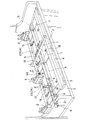
従来の一般的なピアノは、図1及び図2に示すように鍵盤1とアクションベース2のみが図示されているアクション装置体(打弦装置)とが棚板3上にセットされた前・中・奥の3個のレール(筬)4,5,6と妻木7等からなる枠組(鍵盤筬)上に取り付けられ、シフトペダルの操作により作動される突き上げ棒8とベルクランク状のレバー9を介して上記枠組が左右方向へ摺動し、所要のシフトが果たされる仕組である。この仕組では、中レール5は複数個所を接触子11により支持されて棚板3の上面より若干浮き上がっているが、前レール4と奥レール6は相対向面部側が案内ローラ12によりそれぞれ支持されて棚板3の上面より若干浮き上がり、それらの反対側部分が棚板3の上面と接触している。
【0003】
案内ローラ12は一対の木ねじ13,14を用いて棚板3上に取り付けられた調節板15の自由端側に支持され、前レール4と奥レール6の相対向面部側の浮き上がり(棚板3との間隙)が調節できるようになっている。即ち、調節板15は木ねじ13と木ねじ14間が浅い凹面状に湾曲しており、その湾曲部15aの下面を棚板3に埋め込んだ受けねじ16の頭上に当て、該頭部(棚板3の上面と面一である)16aを支点として調節板15の自由端側を木ねじ13,14の締緩操作によって昇降させ、上記浮き上り量を棚板3の表面の反りや凹凸に対応して調節し、前レール4と奥レール6がスムースに摺動できるようになっている。
【0004】
図中、17はレバー9の枢軸18に対して該レバー9の従動側端部に取り付けたシフトローラであり、シフトローラ17は奥レール6の側面に設けられている嵌装部19に自転可能に取り付けられている。21は突き上げ棒8側に作用させた戻しばね、22は奥レール5側に作用させた戻しばねである。なお、図示の場合、アクションベース2は奥レール6上に取り付けられているが、ピアノの種類によっては中レール5と奥レール6に跨って設けられているものもある。
【0005】
【発明が解決しようとする課題】
かかる従来装置では、アクション装置体が組み付けられている奥レール或いは奥レールと中レールにアクション装置体の重量が負担されるため、一部が棚板に接触している奥レールはシフト動作時に棚板との摩擦力が大きく、ペダル操作に重く抵抗感を生じさせることは勿論、関連部材間にがたつきや狂い等を起こさせる要因になっている。本発明はこのような問題を解決したものであって、その目的は、永久磁石同士の反発力を利用して奥レールに見掛け上の浮力を与え、シフト動作が軽く滑らかに行われるように改良したピアノのシフト装置を提供することにある。
【0006】
【課題を解決するための手段】
上記目的を達成するために、本発明の特徴とするピアノのシフト装置は、鍵盤とアクション装置体が組み付けられている枠組が棚板上に摺動可能にセットされているピアノのシフト装置において、棚板と枠組の奥レールには、該両部材の相対向した表面とそれぞれ面一の状態で同極同士が対面するようにして、永久磁石を埋設した構成である。この構成において、永久磁石は棚板と奥レールの複数箇所に間隔を置いて(望ましくは等間隔に)埋設されているのがシフト動作の安定性の面で好ましい。
【0007】
【発明の実施の形態】
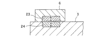
以下に、本発明の実施の形態を前述した従来の一般例の説明に利用した図1,2に図3を加えて説明する。なお、図1,2による先の説明を援用し、その説明での部材と同一部材については同一符号を用いて本発明を説明する。鍵盤1とアクション装置体のアクションベース2とが取り付けられている枠組が棚板3上に摺動可能にセットされているピアノのシフト装置において、棚板3と枠組の奥レール6には、該両部材3,6の相対向した表面とそれぞれ面一の状態で同極同士(SとSまたはNとN)が対面するようにして、複数箇所に永久磁石23,24が埋設され、奥レール6に両永久磁石23,24の反発力により見掛け上の浮力を与えるようにして本発明を実施する。
【0008】
図示の場合、永久磁石23,24は円盤状のものが棚板3と奥レール6の5箇所に等間隔でそれぞれ埋設されているが、その形状は角形でもよいことは勿論である。このように奥レール6に見掛け上の浮力が与えられていることによって、奥レール6はシフト動作時に棚板3との摩擦力が軽減され、鍵盤とアクション装置体を軽くスムースにシフトさせることができる。
【図面の簡単な説明】
【図1】本発明を実施したピアノの要部を一部切り欠いて示す平面図である。
【図2】図1のA−A線断面図である。
【図3】図1のB−B線断面図である。
【符号の説明】
1は鍵盤、2はアクション装置体の一部であるアクションベース、3は棚板、6は奥レール、23,24は永久磁石である。[0001]
BACKGROUND OF THE INVENTION
The present invention relates to a piano shift device which can be applied to either a vertical or flat piano and is improved so that a keyboard and an action device body can be smoothly shifted.
[0002]
[Prior art]
As shown in FIGS. 1 and 2, the conventional general piano has a keyboard 1 and an action device body (string-striking device) in which only the action base 2 is shown on the shelf 3.・ A push-up bar 8 and a bell-crank-
[0003]
The
[0004]
In the figure, 17 is a shift roller attached to the driven side end of the
[0005]
[Problems to be solved by the invention]
In such a conventional device, since the weight of the action device body is borne by the back rail or the back rail and the middle rail to which the action device body is assembled, the back rail, which is partially in contact with the shelf, The frictional force with the plate is large, causing heavy resistance to pedal operation and causing a sense of resistance, as well as causing factors such as rattling and deviation between related members. The present invention solves such a problem, and its purpose is to provide an apparent buoyancy to the back rail by utilizing the repulsive force between the permanent magnets so that the shift operation is light and smooth. An object of the present invention is to provide a piano shift device.
[0006]
[Means for Solving the Problems]
In order to achieve the above object, a piano shift device characterized by the present invention is a piano shift device in which a frame in which a keyboard and an action device body are assembled is slidably set on a shelf board. Permanent magnets are embedded in the rear plate of the shelf and the frame so that the same poles face each other on the opposite surfaces of the two members. In this configuration, the permanent magnets are preferably embedded at a plurality of positions on the shelf board and the back rail (preferably at equal intervals) from the viewpoint of the stability of the shift operation.
[0007]
DETAILED DESCRIPTION OF THE INVENTION
In the following, an embodiment of the present invention will be described with reference to FIGS. In addition, the previous description by FIG.1, 2 is used and this invention is demonstrated using the same code | symbol about the same member as the member in the description. In a piano shift device in which a frame to which a keyboard 1 and an action base 2 of an action device body are attached is slidably set on a shelf 3, the shelf 3 and the
[0008]
In the illustrated case, the
[Brief description of the drawings]
FIG. 1 is a plan view showing a principal part of a piano embodying the present invention with a part cut away.
FIG. 2 is a cross-sectional view taken along line AA in FIG.
FIG. 3 is a cross-sectional view taken along line BB in FIG.
[Explanation of symbols]
1 is a keyboard, 2 is an action base which is a part of the action device body, 3 is a shelf board, 6 is a back rail, and 23 and 24 are permanent magnets.
Claims (2)
Priority Applications (1)
| Application Number | Priority Date | Filing Date | Title |
|---|---|---|---|
| JP2002350473A JP3763096B2 (en) | 2002-10-29 | 2002-10-29 | Piano shift equipment |
Applications Claiming Priority (1)
| Application Number | Priority Date | Filing Date | Title |
|---|---|---|---|
| JP2002350473A JP3763096B2 (en) | 2002-10-29 | 2002-10-29 | Piano shift equipment |
Publications (2)
| Publication Number | Publication Date |
|---|---|
| JP2004151663A true JP2004151663A (en) | 2004-05-27 |
| JP3763096B2 JP3763096B2 (en) | 2006-04-05 |
Family
ID=32463087
Family Applications (1)
| Application Number | Title | Priority Date | Filing Date |
|---|---|---|---|
| JP2002350473A Expired - Fee Related JP3763096B2 (en) | 2002-10-29 | 2002-10-29 | Piano shift equipment |
Country Status (1)
| Country | Link |
|---|---|
| JP (1) | JP3763096B2 (en) |
Families Citing this family (1)
| Publication number | Priority date | Publication date | Assignee | Title |
|---|---|---|---|---|
| JP4901559B2 (en) * | 2007-04-09 | 2012-03-21 | 東洋ピアノ製造株式会社 | Piano keyboard shift device and method for adjusting piano keyboard shift device |
-
2002
- 2002-10-29 JP JP2002350473A patent/JP3763096B2/en not_active Expired - Fee Related
Also Published As
| Publication number | Publication date |
|---|---|
| JP3763096B2 (en) | 2006-04-05 |
Similar Documents
| Publication | Publication Date | Title |
|---|---|---|
| EP2138344B1 (en) | Car seat | |
| EP2040275A3 (en) | Key switch and keyboard | |
| DE602004000987D1 (en) | Table with changeable assortment | |
| MY134353A (en) | An improved front panel mounting device for a drawer | |
| TW200620356A (en) | Key switch device, key board, and key switch assembling jig | |
| WO2006055439A3 (en) | Light mountable on a mounting rail | |
| EP1746573A3 (en) | Keyboard apparatus | |
| JPH0737827Y2 (en) | Cutting device | |
| CN2710095Y (en) | Keyboard instrument | |
| JP3763096B2 (en) | Piano shift equipment | |
| US6921134B1 (en) | Apparatus for adjusting inclination of chair backs | |
| US5361082A (en) | Structure of computer keyboard (II) | |
| JPH07163438A (en) | Chair with slide seat board | |
| US6148705A (en) | Table saw combination | |
| US20050172773A1 (en) | Rip guide adjusting device of circular saw | |
| JP4326384B2 (en) | Electronic keyboard instrument keyboard device | |
| AU2003224503A1 (en) | Aligning means for an injection-molding device | |
| CN2600214Y (en) | Bar feeding device | |
| AU2003299332A1 (en) | Spring switch for a monorail guide circuit | |
| CN223294167U (en) | Belt tension adjustment structure for inkjet printer | |
| JP2001288825A (en) | Joint device for floor | |
| CN206631215U (en) | A kind of block of multidirectional regulation | |
| DE50213377D1 (en) | Panel, in particular laminate panel | |
| JPH10240232A (en) | Keyboard device | |
| CN218886748U (en) | Wall-attached type aluminum alloy guide board |
Legal Events
| Date | Code | Title | Description |
|---|---|---|---|
| A621 | Written request for application examination |
Free format text: JAPANESE INTERMEDIATE CODE: A621 Effective date: 20040803 |
|
| A977 | Report on retrieval |
Free format text: JAPANESE INTERMEDIATE CODE: A971007 Effective date: 20051124 |
|
| TRDD | Decision of grant or rejection written | ||
| A01 | Written decision to grant a patent or to grant a registration (utility model) |
Free format text: JAPANESE INTERMEDIATE CODE: A01 Effective date: 20051206 |
|
| A61 | First payment of annual fees (during grant procedure) |
Free format text: JAPANESE INTERMEDIATE CODE: A61 Effective date: 20060105 |
|
| R150 | Certificate of patent or registration of utility model |
Free format text: JAPANESE INTERMEDIATE CODE: R150 Ref document number: 3763096 Country of ref document: JP Free format text: JAPANESE INTERMEDIATE CODE: R150 |
|
| FPAY | Renewal fee payment (event date is renewal date of database) |
Free format text: PAYMENT UNTIL: 20100127 Year of fee payment: 4 |
|
| R250 | Receipt of annual fees |
Free format text: JAPANESE INTERMEDIATE CODE: R250 |
|
| FPAY | Renewal fee payment (event date is renewal date of database) |
Free format text: PAYMENT UNTIL: 20130127 Year of fee payment: 7 |
|
| R250 | Receipt of annual fees |
Free format text: JAPANESE INTERMEDIATE CODE: R250 |
|
| FPAY | Renewal fee payment (event date is renewal date of database) |
Free format text: PAYMENT UNTIL: 20140127 Year of fee payment: 8 |
|
| R250 | Receipt of annual fees |
Free format text: JAPANESE INTERMEDIATE CODE: R250 |
|
| R250 | Receipt of annual fees |
Free format text: JAPANESE INTERMEDIATE CODE: R250 |
|
| R250 | Receipt of annual fees |
Free format text: JAPANESE INTERMEDIATE CODE: R250 |
|
| R250 | Receipt of annual fees |
Free format text: JAPANESE INTERMEDIATE CODE: R250 |
|
| R250 | Receipt of annual fees |
Free format text: JAPANESE INTERMEDIATE CODE: R250 |
|
| S111 | Request for change of ownership or part of ownership |
Free format text: JAPANESE INTERMEDIATE CODE: R313113 |
|
| R350 | Written notification of registration of transfer |
Free format text: JAPANESE INTERMEDIATE CODE: R350 |
|
| R250 | Receipt of annual fees |
Free format text: JAPANESE INTERMEDIATE CODE: R250 |
|
| LAPS | Cancellation because of no payment of annual fees |