JP2004149092A - Power steering device - Google Patents
Power steering device Download PDFInfo
- Publication number
- JP2004149092A JP2004149092A JP2002319689A JP2002319689A JP2004149092A JP 2004149092 A JP2004149092 A JP 2004149092A JP 2002319689 A JP2002319689 A JP 2002319689A JP 2002319689 A JP2002319689 A JP 2002319689A JP 2004149092 A JP2004149092 A JP 2004149092A
- Authority
- JP
- Japan
- Prior art keywords
- steering
- vehicle speed
- switching
- solenoid
- command value
- Prior art date
- Legal status (The legal status is an assumption and is not a legal conclusion. Google has not performed a legal analysis and makes no representation as to the accuracy of the status listed.)
- Pending
Links
Images


Landscapes
- Steering Control In Accordance With Driving Conditions (AREA)
- Power Steering Mechanism (AREA)
Abstract
Description
【0001】
【発明の属する技術分野】
この発明は、パワーシリンダ側に導く流量を制御する流量制御弁を備えたパワーステアリング装置に関する。
【0002】
【従来の技術】
従来の流量制御装置として、例えば特許文献1に記載されたものが知られている。この従来例を示したのが図3である。
図示したように、流量制御弁Vに、ポンプPを接続している。
上記流量制御弁Vのスプール1は、その一端を一方のパイロット室2に臨ませ、他端を他方のパイロット室3に臨ませている。上記一方のパイロット室2は、ポンプポート4を介してポンプPに常時連通している。また、他方のパイロット室3にはスプリング5を介在させている。このようにした両パイロット室2,3は、ソレノイドSOLの励磁電流Iに応じて開度を制御する可変オリフィスaを介して、たがいに連通している。
【0003】
すなわち、一方のパイロット室2は、流路6→可変オリフィスa→流路7を経由してパワーシリンダ8を制御するステアリングバルブ9の流入側に連通している。また、他方のパイロット室3は、流路10および流路7を介してステアリングバルブ9の流入側に連通している。
したがって、上記両パイロット室2,3は、可変オリフィスaを介して連通することになり、可変オリフィスaの上流側の圧力が一方のパイロット室2に作用し、下流側の圧力が他方のパイロット室3に作用することになる。
【0004】
そして、スプール1は、一方のパイロット室2の作用力と、他方のパイロット室3の作用力およびスプリング5の作用力とがバランスした位置を保つが、そのバランス位置において、前記タンクポート11の開度が決められる。
今、エンジン等からなるポンプ駆動源12が停止していると、ポンプポート4に圧油が供給されない。ポンプポート4に圧油が供給されなければ、両パイロット室2,3には圧力が発生しないので、スプール1はスプリング5の作用で図示のノーマル位置を保つ。
【0005】
上記の状態からポンプPが駆動して、ポンプポート4に圧油が供給されると、可変オリフィスaに流れができるので、そこに差圧が発生する。この差圧の作用で、両パイロット室2,3に圧力差が発生し、この圧力差に応じてスプール1がスプリング5に抗して移動し、上記バランス位置を保つ。
このようにスプール1がスプリング5に抗して移動することによって、タンクポート11の開度を大きくするが、このときのタンクポート11の開度に応じて、ステアリングバルブ9側に導かれる制御流量QPと、タンクTあるいはポンプPに還流される戻り流量QTの分配比が決まる。言い換えれば、タンクポート11の開度に応じて制御流量QPが決まることになる。
【0006】
上記のように制御流量QPが、スプール1の移動位置で決まるタンクポート11の開度に応じて制御されるということは、結局は、可変オリフィスaの開度に応じて制御流量QPが決まることになる。なぜなら、スプール1の移動位置は、両パイロット室2,3の圧力差で決まるとともに、この圧力差を決めているのが可変オリフィスaの開度だからである。
【0007】
したがって、車速や操舵状況に応じて、制御流量QPを制御するためには、可変オリフィスaの開度、すなわちソレノイドSOLの励磁電流を制御すればよいことになる。
なぜなら、可変オリフィスaは、ソレノイドSOLの励磁電流の大きさによって、開度を最大から最小まで任意に制御できるからである。
【0008】
なお、前記ステアリングバルブ9は、図示していないステアリングホィールの入力トルク(操舵トルク)に応じて、パワーシリンダ8の圧力を制御するものである。例えば、操舵トルクが大きければ、パワーシリンダ8への供給量を大きくし、操舵トルクが小さければそれに応じてパワーシリンダ8の圧力を小さくするようにしている。この操舵トルクとステアリングバルブ9の切り換え量は、図示していないトーションバーなどのねじれ反力によって決まることになる。
【0009】
上記のように操舵トルクが大きいときに、ステアリングバルブ9の切り換え量を大きくすれば、その分、パワーシリンダ8によるアシスト力が大きくなる。反対に、ステアリングバルブ9の切り換え量を小さくすれば、上記アシスト力は小さくなる。
そして、ピストンの移動速度によって決まるパワーシリンダ8の必要(要求)流量QMと、流量制御弁Vで決められる制御流量QPとをなるべく等しくすれば、ポンプP側のエネルギー損失を低く抑えることができる。なぜなら、ポンプP側のエネルギー損失は、制御流量QPとパワーシリンダ8の必要流量QMとの差によって発生するからである。
【0010】
上記のように制御流量QPを、パワーシリンダ8の必要流量QMにできるだけ近づけるために、可変オリフィスaの開度を制御するのが、ソレノイドSOLに対するソレノイド電流指令値SIであり、このソレノイド電流指令値SIを制御するのが、コントローラCである。
このコントローラCには、操舵角センサ16と車速センサ17とを接続し、これら両センサの出力信号に基づいて、ソレノイドSOLの励磁電流を制御するようにしている。すなわち、上記コントローラCは、操舵角センサ16からの操舵角信号によって、ソレノイド電流指令値Ivを決定するテーブルを備え、車速センサ17からの車速信号によってソレノイド電流指令値Ivを決定するテーブルを備えている。そして、これらテーブル値に基づいてソレノイドSOLの励磁電流を制御している。
【0011】
なお、図中符号18はスプール1の先端に形成したスリットで、スプール1が図示の位置にあるときにも、このスリット18を介して一方のパイロット室2が流路7に常時連通するようにしている。言い換えると、スプール1が図示の状態にあって、流路6を閉じているようなときにも、ポンプPの吐出油が、このスリット18を介して、ステアリングバルブ9側に供給されるようにしている。
【0012】
このように微少流量であるが、ステアリングバルブ9側に圧油を供給するようにしたのは、キックバック等の外乱の防止、および応答性の確保を目的にしているからである。
なお、符号19は、コントローラCとソレノイドSOLとの間に接続したソレノイドSOLの駆動装置ある。
また、符号13,14は絞りであり、符号15はリリーフ弁である。
【0013】
【特許文献1】
特開2001−260917号公報(第3〜6頁、図1)
【0014】
【発明が解決しようとする課題】
上記のように従来は、車速からソレノイド電流指令値Ivを決定するとき、あるいは操舵角からソレノイド電流指令値Iθを決定するときには、それぞれコントローラCに備えたテーブルに基づいていた。しかし、上記テーブルは、それぞれ一種類ずつしか備えていなかった。
【0015】
したがって、例えば、腕力の強い人にあわせて、上記テーブルの特性を決めたときには、パワーシリンダのアシスト力が小さめになる。アシスト力が小さい場合に、腕力の弱い人がこれを操作すれば、ステアリングホィールが重たすぎるということが発生する。
逆に、腕力の弱い人にあわせて、上記テーブルの特性を決めたときには、パワーシリンダのアシスト力が大きめになる。アシスト力が大きめになると、これを腕力の強い人が操作した場合には、ステアリングホィールが軽すぎるという状況が生じる。
【0016】
つまり、上記のような設定ではその制御特性がどうしても一義的に決まってしまい、各ドライバーにとって、必ずしも最適な操舵フィーリングが実現できないという問題があった。
この発明の目的は、各ドライバーにあった制御特性を選択することによって、最適な操舵フィーリングを実現できるパワーステアリング装置を提供することである。
【0017】
【課題を解決するための手段】
第1の発明は、パワーシリンダを制御するステアリングバルブと、このステアリングバルブの上流側に設けた可変オリフィスと、この可変オリフィスの開度を制御するソレノイドと、このソレノイド励磁電流を制御するコントローラと、ポンプから供給される流量を上記可変オリフィスの開度に応じてステアリングバルブに導く制御流量とタンクまたはポンプに環流させる戻り流量とに分配する流量制御弁と、操舵角を検出する操舵角センサとを備え、上記コントローラは、上記操舵角に基づいてソレノイド電流指令値Iθを決める操舵角用テーブルを備えるとともに、この操舵角用テーブルにはそれぞれ特性の異なる複数の切替テーブルを備え、切替信号に応じて上記切替テーブルを選択可能にしたことを特徴とする。
【0018】
第2の発明は、パワーシリンダを制御するステアリングバルブと、このステアリングバルブの上流側に設けた可変オリフィスと、この可変オリフィスの開度を制御するソレノイドと、このソレノイド励磁電流を制御するコントローラと、ポンプから供給される流量を上記可変オリフィスの開度に応じてステアリングバルブに導く制御流量とタンクまたはポンプに環流させる戻り流量とに分配する流量制御弁と、操舵角速度を検出または算出する操舵角速度特定手段とを備え、上記コントローラは、上記操舵角速度に基づいてソレノイド電流指令値Iωを決める操舵角速度用テーブルを備えるとともに、この操舵角速度用テーブルにはそれぞれ特性の異なる複数の切替テーブルを備え、切替信号に応じて上記切替テーブルを選択可能にしたことを特徴とする。
【0019】
第3の発明は、パワーシリンダを制御するステアリングバルブと、このステアリングバルブの上流側に設けた可変オリフィスと、この可変オリフィスの開度を制御するソレノイドと、このソレノイド励磁電流を制御するコントローラと、ポンプから供給される流量を上記可変オリフィスの開度に応じてステアリングバルブに導く制御流量とタンクまたはポンプに環流させる戻り流量とに分配する流量制御弁と、車速を検出する車速センサとを備え、上記コントローラは、上記車速に基づいてソレノイド電流指令値Ivを決める車速用テーブルを備えるとともに、この車速用テーブルにはそれぞれ特性の異なる複数の切替テーブルを備え、切替信号に応じて上記切替テーブルを選択可能にしたことを特徴とする。
【0020】
第4の発明は、パワーシリンダを制御するステアリングバルブと、このステアリングバルブの上流側に設けた可変オリフィスと、この可変オリフィスの開度を制御するソレノイドと、このソレノイド励磁電流を制御するコントローラと、ポンプから供給される流量を上記可変オリフィスの開度に応じてステアリングバルブに導く制御流量とタンクまたはポンプに環流させる戻り流量とに分配する流量制御弁と、トルクを検出するトルクセンサとを備え、上記コントローラは、上記トルクに基づいてソレノイド電流指令値Itを決めるトルク用テーブルを備えるとともに、このトルク用テーブルにはそれぞれ特性の異なる複数の切替テーブルを備え、切替信号に応じて上記切替テーブルを選択可能にしたことを特徴とする。
【0021】
第5の発明は、第1および第2の発明を前提とし、車速を検出する車速センサを備え、コントローラは、上記車速に基づいてソレノイド電流指令値Ivを決める車速用テーブルを備えるとともに、この車速用テーブルにはそれぞれ特性の異なる複数の切替テーブルを備え、切替信号に応じて上記切替テーブルを選択可能にしたことを特徴とする。
【0022】
第6の発明は、第1の発明を前提とし、操舵角速度を検出または算出する操舵角速度特定手段を備え、コントローラは、上記操舵角速度に基づいてソレノイド電流指令値Iωを決める操舵角速度用テーブルを備えるとともに、この操舵角用テーブルにはそれぞれ特性の異なる複数の切替テーブルを備え、切替信号に応じて上記切替テーブルを選択可能にしたことを特徴とする。
【0023】
第7の発明は、第1の発明を前提とし、車速を検出する車速センサと、操舵角速度を検出または算出する操舵角速度特定手段とを備え、コントローラは、上記車速に基づいてソレノイド電流指令値Ivを決める車速用テーブルを備えるとともに、それぞれ特性の異なる複数の切替テーブルを備え、かつ、上記操舵角速度に基づいてソレノイド電流指令値Iωを決める操舵角速度用テーブルを備えるとともに、それぞれ特性の異なる複数の切替テーブルを備え、切替信号に応じて上記車速用の切替テーブルおよび操舵角速度用の切替テーブルを選択可能にしたことを特徴とする。
【0024】
第8の発明は、第4の発明を前提とし、車速を検出する車速センサを備え、コントローラは、上記車速に基づいてソレノイド電流指令値Ivを決める車速用テーブルを備えるとともに、この車速用テーブルにはそれぞれ特性の異なる複数の切替テーブルを備え、切替信号に応じて上記切替テーブルを選択可能にしたことを特徴とする。
【0025】
【発明の実施の形態】
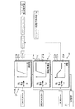
図1、2に示した実施形態は、コントローラCに特徴を有するものである。したがって、以下では、コントローラCについて詳細に説明し、従来と同じ構成要素については同じ符号を付してその説明を省略する。
【0026】
上記コントローラCには、操舵角信号θからソレノイド電流指令値Iθを決定する操舵角用テーブル20と、操舵角速度信号ωからソレノイド電流指令値Iωを決定する操舵角速度用テーブル21と、車速信号vからソレノイド電流指令値Ivを決定する車速用テーブル22とを備えている。
さらに、上記コントローラCには、各テーブル20,21,22と接続する切替部23を備えている。
【0027】
上記操舵角用テーブル20は、特性の異なる切替テーブル20a、20b、20cを備えている。上記操舵角用の切替テーブルは例えば、図2(a)、(b)、(c)に示したような特性を有している。
すなわち、図2(a)に示した切替テーブル20aでは操舵角信号θに対してソレノイド電流指令値Iθが大きめに出力されるようにしている。図2(c)に示した切替テーブル20cでは小さめに出力されるようにしている。そして、図2(b)に示した切替テーブル20bでは、上記切替テーブル20aと20cとの中間くらいが出力されるようにしている。
【0028】
また、上記操舵角用テーブル20によって決定されるソレノイド電流指令値Iθは、その操舵角信号θと制御流量QPとの関係がリニアな特性になる理論値に基づいて決めている。
【0029】
また、上記操舵角速度用テーブル21にも、特性の異なる切替テーブル21a、21b、21cを備えている。この操舵角速度用テーブル21によって決められるソレノイド電流指令値Iωは、操舵角速度信号ωと制御流量QPとがリニアな特性になる理論値に基づいて決めている。
【0030】
なお、上記操舵角速度用テーブル21に入力される操舵角速度信号ωは、操舵角速度特定手段として操舵角センサ16を用い、この操舵角センサ16からの操舵角信号θを微分して算出したものである。この操舵角速度特定手段として操舵角速度センサを別に設け、この操舵角速度センサから直接操舵角速度信号ωを求めてもよい。
【0031】
また、上記車速用テーブル22にも、特性の異なる切替テーブル22a、22b、22cを備えている。この車速用テーブル21によって決められるソレノイド電流指令値Ivは、車速が低速域では1を出力し、高速域ではゼロを出力する。また、低速域と高速域との間の中速域では、1からゼロまでの小数点以下の値を出力するようにしている。
【0032】
また、上記コントローラCには、上記切替テーブル20a〜20c、21a〜21c、22a〜22cの組み合わせをあらかじめ記憶させるようにしている。例えば、腕力の強い人にあわせて、車速用の切替テーブル22aとを組み合わせたものをAタイプとして設定している。このAタイプの場合には、パワーシリンダのアシスト力が小さめに出力されるように制御される。
また、腕力の弱い人にあわせて、切替テーブルの組み合わせを設定したものをCタイプとしている。このCタイプの場合には、パワーシリンダのアシスト力が大きめに出力されるように制御される。また、上記AタイプとCタイプの中間の制御をする組み合わせを設定したものをBタイプとしている。
【0033】
上記A〜Cタイプは、ドライバーによって選択することができるようにしている。そして、ドライバーが上記いずれかのタイプを選択すれば、その選択信号がコントローラCの切替部23に入力される。切替部23にドライバーからの信号が入力されたら、切替部23はこの信号に応じて設定された各切替テーブルを選択する。すなわち、操舵各用の切替テーブル20a〜20cの中から設定されたいずれか一つのテーブルを選択する。同様に、操舵角速度用の切替テーブル21a〜21cの中からいずれか一つ、車速用の切替テーブル22a〜22cの中からいずれか一つをそれぞれ選択する。そして、この選択された切替テーブルに基づいて以下の制御をおこなう。
【0034】
まず、コントローラCは、上記操舵角信号θから選択したテーブル20a〜20cに基づいてソレノイド電流指令値Iθを決定し、操舵角速度信号ωから選択したテーブル21a〜21cに基づいてソレノイド電流指令値Iωを決定する。上記ソレノイド電流指令値Iθおよびソレノイド電流指令値Iωは、操舵角信号θおよび操舵角速度信号ωが、ある設定値以上にならなければいずれもゼロを出力するようにしている。つまり、ステアリングホィールが中立あるいはその近傍にあるときには、上記ソレノイド電流指令値IθもIωもゼロになるようにしている。
上記ソレノイド電流指令値Iθとソレノイド電流指令値Iωとを決定したら、これら両者を加算する。
【0035】
上記のようにして両ソレノイド電流指令値Iθ、Iωを加算したら、この加算値(Iθ+Iω)に、車速信号vに基づいたソレノイド電流指令値Ivを乗算する。
この車速信号vに基づいたソレノイド電流指令値Ivは、車速が低速域では1を出力し、高速域ではゼロを出力する。また、低速域と高速域との間の中速域では、1からゼロまでの小数点以下の値を出力するようにしている。
【0036】
したがって、上記加算値(Iθ+Iω)に車速信号vに基づいたソレノイド電流指令値Ivを乗算すれば、低速域では(Iθ+Iω)がそのまま出力され、高速域では(Iθ+Iω)がゼロになる。
また、中速域では、速度が上がれば上がるほどそれに反比例した値が出力されることになる。
さらに、上記(Iθ+Iω)×Ivにスタンバイソレノイド電流指令値Isを加算する。そして、これをソレノイド電流指令値IとしてコントローラCから出力し、このソレノイド電流指令値Iを基にソレノイド励磁電流を制御する。
【0037】
上記スタンバイソレノイド電流指令値Isは、可変オリフィスaの開度を制御するソレノイドSOLに所定の電流が常に供給されるようにするためのものである。つまり、操舵角信号θ、操舵角速度信号ωおよび車速信号vに基づいたソレノイド電流指令値が全てゼロの場合でも、スタンバイソレノイド電流指令値Isによって可変オリフィスaが一定の開度を保ち、所定のスタンバイ流量QSがステアリングバルブ9側に常に供給されるようにしている。
【0038】
このように一定のスタンバイ流量QSを確保する理由は、以下の通りである。すなわち、タイヤにキックバック等の外乱やセルフアライニングトルク等による抗力が作用すると、それがパワーシリンダ8のロッドに作用するが、このような場合であっても、スタンバイ流量QSを確保しておけば、タイヤがふらつくのを防止できるからである。また、スタンバイ流量QSを確保しておけば、それが全然ないときよりも、目的の制御流量に短時間で達することができる分、応答性を向上させることができるからである。
また、どんな場合でもスタンバイ流量は必ず確保されるので、低速域での直進走行時であっても、キックバック等による外乱に対抗でき、また、操舵時の応答性も良好に保つことができる。
【0039】
上記のような実施形態によれば、ドライバーは自分にあったタイプを選択すれば、そのタイプに応じた最適な操舵フィーリングを実現することができる。
なお、上記実施形態では、コントローラCは操舵角用テーブル20、操舵角速度用テーブル21、車速用テーブル22を備えるようにしているが、いずれかひとつの信号に対するテーブルを備えるようにしてもよい。また、例えば、操舵角用テーブル20と操舵角速度用テーブル21、操舵角速度テーブル21と車速用テーブル22、操舵角用テーブル20と車速用テーブル22というように、様々な組み合わせを作るとともに、この組み合わせを変えて用いるようにしてもよい。ただし、いずれの場合にも、特性の異なる切替テーブルを複数備えるようにする。
また、上記複数の信号をコントローラCに入力し、この信号に対応するテーブルを備えることによって、制御のバリエーションが豊富になり、より一層ドライバーの操舵フィーリングを快適にすることができる。
さらに、トルクを検出するトルクセンサを備えるとともに、トルク用テーブルを備え、このトルク用テーブルに基づいてソレノイド電流指令値を決定するようにしてもよい。このトルク用テーブルにも異なる特性を示す切替テーブルを複数備えるようにする。
【0040】
また、コントローラCにはあらかじめ3種類のタイプを用意して、ドライバーはこの中から自分にあったタイプを選択するようにしているが、直接切替テーブルを選択するようにしてもよい。このように、切替テーブルを選択するようにすれば、制御のバリエーションがより多くなり、より一層ドライバーに適した操舵フィーリングを実現することができる。
さらに、ドライバーがタイプあるいは切替テーブルを選択する手段としては、ドライバーがコントローラCを操作して選択するようにしてもよいし、メモリーカードに記憶させて、このメモリーカードからコントローラCに入力するようにしてもよい。
また、この実施形態では各テーブルに切替テーブルをそれぞれ3種類ずつ備えるようにしているが、テーブル値を変えることができれば、3種類に限ったものではなく、何種類でもよい。
【0041】
【発明の効果】
第1〜第4の発明によれば、ソレノイド電流指令値Iを決定するテーブルは、特性の異なる切替テーブルを複数備えるので、その分、バリエーションに富んだ制御特性を得ることができる。したがって、ドライバーに適した制御を実現することができる。
【0042】
第5〜第9の発明によれば、ソレノイドSOLを制御するソレノイド電流指令値複数備えるとともに、各ソレノイド電流指令値を決定する切替テーブルを複数備えるようにしたので、より一層制御のバリエーションを増やすことができる。したがって、その分ドライバーに適した制御を実現することができる。
【図面の簡単な説明】
【図1】第1実施例のコントローラの通常制御の制御系を示すブロック図である。
【図2】(a)操舵角用テーブル21aを示すテーブルである。
(b)操舵角用テーブル21bを示すテーブルである。
(c)操舵角用テーブル21cを示すテーブルである。
【図3】従来例の回路図である。
【符号の説明】
8 パワーシリンダ
9 ステアリングバルブ
17 車速センサ
21 操舵角用テーブル
22 操舵角速度用テーブル
23 車速用テーブル
V 流量制御弁
P ポンプ
a 可変オリフィス
QP 制御流量
QT 戻り流量
C コントローラ
v 車速信号
I ソレノイド電流指令値[0001]
TECHNICAL FIELD OF THE INVENTION
The present invention relates to a power steering device provided with a flow control valve for controlling a flow guided to a power cylinder.
[0002]
[Prior art]
BACKGROUND ART As a conventional flow control device, for example, a device described in
As shown, a pump P is connected to the flow control valve V.
The
[0003]
That is, one
Therefore, the two
[0004]
Then, the
If the
[0005]
When the pump P is driven from the above state and the pressure oil is supplied to the
As described above, the opening of the tank port 11 is increased by the movement of the
[0006]
The fact that the control flow rate QP is controlled in accordance with the opening of the tank port 11 determined by the moving position of the
[0007]
Therefore, in order to control the control flow rate QP according to the vehicle speed and the steering situation, the opening degree of the variable orifice a, that is, the exciting current of the solenoid SOL may be controlled.
This is because the opening of the variable orifice a can be arbitrarily controlled from the maximum to the minimum depending on the magnitude of the exciting current of the solenoid SOL.
[0008]
The
[0009]
If the switching amount of the
If the required (required) flow rate QM of the power cylinder 8 determined by the moving speed of the piston and the control flow rate QP determined by the flow control valve V are made as equal as possible, the energy loss on the pump P side can be suppressed low. This is because the energy loss on the pump P side is caused by the difference between the control flow rate QP and the required flow rate QM of the power cylinder 8.
[0010]
In order to make the control flow rate QP as close as possible to the required flow rate QM of the power cylinder 8 as described above, the opening degree of the variable orifice a is controlled by the solenoid current command value SI for the solenoid SOL. The controller C controls the SI.
The
[0011]
In the drawing,
[0012]
The reason why the pressure oil is supplied to the
[0013]
[Patent Document 1]
JP 2001-260917 A (
[0014]
[Problems to be solved by the invention]
As described above, conventionally, when the solenoid current command value Iv is determined from the vehicle speed, or when the solenoid current command value Iθ is determined from the steering angle, the table provided in the controller C is used. However, each of the tables has only one type.
[0015]
Therefore, for example, when the characteristics of the table are determined according to a person having strong arm strength, the assisting force of the power cylinder becomes smaller. If the assist force is small and a person with weak arm operates it, the steering wheel may become too heavy.
Conversely, when the characteristics of the table are determined in accordance with a person having weak arm strength, the assisting force of the power cylinder becomes larger. When the assisting force is increased, when a person with strong arm operates the assisting force, a situation occurs in which the steering wheel is too light.
[0016]
In other words, with the above settings, the control characteristics are definitely determined uniquely, and there is a problem that the optimum steering feeling cannot always be realized for each driver.
An object of the present invention is to provide a power steering device capable of realizing an optimum steering feeling by selecting a control characteristic suitable for each driver.
[0017]
[Means for Solving the Problems]
A first invention provides a steering valve for controlling a power cylinder, a variable orifice provided upstream of the steering valve, a solenoid for controlling the opening of the variable orifice, a controller for controlling the solenoid exciting current, A flow control valve that distributes a flow supplied from a pump to a control flow that guides a steering valve according to the opening degree of the variable orifice and a return flow that recirculates to a tank or a pump, and a steering angle sensor that detects a steering angle. The controller includes a steering angle table that determines a solenoid current command value Iθ based on the steering angle, and the steering angle table includes a plurality of switching tables having different characteristics, and the controller according to a switching signal. The switching table can be selected.
[0018]
A second invention provides a steering valve for controlling a power cylinder, a variable orifice provided upstream of the steering valve, a solenoid for controlling the opening of the variable orifice, a controller for controlling the solenoid exciting current, A flow control valve for distributing a flow supplied from a pump to a control flow for guiding the steering valve according to the opening degree of the variable orifice and a return flow for recirculating the tank or the pump, and a steering angular velocity identification for detecting or calculating the steering angular velocity Means, the controller includes a steering angular velocity table for determining a solenoid current command value Iω based on the steering angular velocity, and the steering angular velocity table includes a plurality of switching tables having different characteristics, and a switching signal. That the above switching table can be selected according to And it features.
[0019]
A third invention provides a steering valve for controlling a power cylinder, a variable orifice provided upstream of the steering valve, a solenoid for controlling the opening of the variable orifice, a controller for controlling the solenoid exciting current, A flow control valve that distributes a flow supplied from a pump to a control flow guided to a steering valve according to an opening degree of the variable orifice and a return flow to be recirculated to a tank or a pump, and a vehicle speed sensor that detects a vehicle speed, The controller includes a vehicle speed table that determines a solenoid current command value Iv based on the vehicle speed, the vehicle speed table includes a plurality of switching tables having different characteristics, and selects the switching table according to a switching signal. It is made possible.
[0020]
A fourth invention provides a steering valve for controlling a power cylinder, a variable orifice provided upstream of the steering valve, a solenoid for controlling the opening of the variable orifice, a controller for controlling the solenoid exciting current, A flow control valve that distributes a flow supplied from a pump to a control flow guided to a steering valve according to the opening degree of the variable orifice and a return flow returned to a tank or a pump, and a torque sensor that detects torque, The controller includes a torque table for determining the solenoid current command value It based on the torque, the torque table includes a plurality of switching tables having different characteristics, and selects the switching table according to a switching signal. It is made possible.
[0021]
The fifth invention is based on the first and second inventions, and includes a vehicle speed sensor for detecting a vehicle speed, a controller including a vehicle speed table for determining a solenoid current command value Iv based on the vehicle speed, and The switching table is provided with a plurality of switching tables having different characteristics, and the switching table can be selected according to a switching signal.
[0022]
The sixth invention is based on the first invention and includes a steering angular velocity specifying means for detecting or calculating a steering angular velocity, and the controller includes a steering angular velocity table for determining a solenoid current command value Iω based on the steering angular velocity. In addition, the steering angle table includes a plurality of switching tables having different characteristics, and the switching table can be selected according to a switching signal.
[0023]
The seventh invention is based on the first invention, and includes a vehicle speed sensor for detecting a vehicle speed, and a steering angular speed specifying means for detecting or calculating a steering angular speed, and the controller is configured to control the solenoid current command value Iv based on the vehicle speed. , A plurality of switching tables having different characteristics, and a steering angular speed table for determining the solenoid current command value Iω based on the steering angular speed. A switching table for the vehicle speed and a switching table for the steering angular velocity can be selected according to a switching signal.
[0024]
The eighth invention is based on the fourth invention and includes a vehicle speed sensor for detecting a vehicle speed, the controller includes a vehicle speed table for determining a solenoid current command value Iv based on the vehicle speed, and the controller includes a vehicle speed table. Is provided with a plurality of switching tables having different characteristics, and the switching table can be selected according to a switching signal.
[0025]
BEST MODE FOR CARRYING OUT THE INVENTION
The embodiment shown in FIGS. 1 and 2 has a feature in the controller C. Accordingly, hereinafter, the controller C will be described in detail, and the same reference numerals will be given to the same components as those in the related art, and the description thereof will be omitted.
[0026]
The controller C includes a steering angle table 20 for determining a solenoid current command value Iθ from the steering angle signal θ, a steering angular speed table 21 for determining a solenoid current command value Iω from the steering angular speed signal ω, and a vehicle speed signal v. A vehicle speed table 22 for determining the solenoid current command value Iv.
Further, the controller C has a
[0027]
The steering angle table 20 includes switching tables 20a, 20b, and 20c having different characteristics. The switching table for steering angle has, for example, characteristics as shown in FIGS. 2 (a), 2 (b) and 2 (c).
That is, in the switching table 20a shown in FIG. 2A, the solenoid current command value Iθ is set to be larger than the steering angle signal θ. In the switching table 20c shown in FIG. 2C, the output is made smaller. Then, in the switching table 20b shown in FIG. 2B, an intermediate portion between the switching tables 20a and 20c is output.
[0028]
The solenoid current command value Iθ determined by the steering angle table 20 is determined based on a theoretical value that makes the relationship between the steering angle signal θ and the control flow rate QP linear characteristics.
[0029]
The steering angular velocity table 21 also includes switching tables 21a, 21b, and 21c having different characteristics. The solenoid current command value Iω determined by the steering angular velocity table 21 is determined based on a theoretical value that makes the steering angular velocity signal ω and the control flow rate QP linear characteristics.
[0030]
The steering angular velocity signal ω input to the steering angular velocity table 21 is calculated by differentiating the steering angle signal θ from the
[0031]
The table 22 for the vehicle speed also includes switching tables 22a, 22b, and 22c having different characteristics. The solenoid current command value Iv determined by the vehicle speed table 21
[0032]
Further, the controller C stores in advance a combination of the switching tables 20a to 20c, 21a to 21c, and 22a to 22c. For example, a combination with a switching table 22a for the vehicle speed is set as the A type according to a person having strong strength. In the case of the A type, control is performed so that the assisting force of the power cylinder is output to be relatively small.
In addition, a type in which a combination of switching tables is set according to a person having weak strength is a C type. In the case of the C type, control is performed so that the assisting force of the power cylinder is output to be relatively large. A type in which a combination for performing control between the A type and the C type is set is referred to as a B type.
[0033]
The above A to C types can be selected by a driver. Then, when the driver selects one of the above types, the selection signal is input to the
[0034]
First, the controller C determines the solenoid current command value Iθ based on the tables 20a to 20c selected from the steering angle signal θ, and determines the solenoid current command value Iω based on the tables 21a to 21c selected from the steering angular speed signal ω. decide. If the steering angle signal θ and the steering angular velocity signal ω do not exceed a certain set value, the solenoid current command value Iθ and the solenoid current command value Iω output zero. That is, when the steering wheel is at or near neutral, both the solenoid current command values Iθ and Iω are set to zero.
After the solenoid current command value Iθ and the solenoid current command value Iω are determined, both are added.
[0035]
When the two solenoid current command values Iθ and Iω are added as described above, the sum (Iθ + Iω) is multiplied by a solenoid current command value Iv based on the vehicle speed signal v.
The solenoid current command value Iv based on the vehicle speed
[0036]
Therefore, if the addition value (Iθ + Iω) is multiplied by the solenoid current command value Iv based on the vehicle speed signal v, (Iθ + Iω) is output as it is in a low speed region, and (Iθ + Iω) becomes zero in a high speed region.
In the medium speed range, a value that is inversely proportional to the speed increases as the speed increases.
Further, the standby solenoid current command value Is is added to (Iθ + Iω) × Iv. This is output from the controller C as a solenoid current command value I, and the solenoid excitation current is controlled based on the solenoid current command value I.
[0037]
The standby solenoid current command value Is is for ensuring that a predetermined current is constantly supplied to the solenoid SOL that controls the opening of the variable orifice a. That is, even when the solenoid current command values based on the steering angle signal θ, the steering angular speed signal ω, and the vehicle speed signal v are all zero, the variable orifice a maintains a constant opening degree by the standby solenoid current command value Is, and a predetermined standby The flow rate QS is always supplied to the
[0038]
The reason for securing the constant standby flow rate QS in this way is as follows. That is, when a disturbance due to kickback or the like or a drag due to self-aligning torque or the like acts on the tire, it acts on the rod of the power cylinder 8. Even in such a case, the standby flow rate QS can be secured. This is because the tire can be prevented from wobbling. Further, if the standby flow rate QS is ensured, the responsiveness can be improved because the target control flow rate can be reached in a shorter time than when there is no standby flow rate QS.
In any case, the standby flow rate is always ensured, so that even when the vehicle is running straight in a low-speed range, disturbance due to kickback or the like can be countered, and good responsiveness during steering can be maintained.
[0039]
According to the above-described embodiment, if the driver selects a type that suits him / her, an optimal steering feeling according to that type can be realized.
In the above embodiment, the controller C includes the steering angle table 20, the steering angular velocity table 21, and the vehicle speed table 22, but may include a table for any one of the signals. In addition, various combinations are made, for example, the steering angle table 20 and the steering angular velocity table 21, the steering angular velocity table 21 and the vehicle speed table 22, and the steering angle table 20 and the vehicle speed table 22. It may be changed and used. However, in any case, a plurality of switching tables having different characteristics are provided.
Further, by inputting the plurality of signals to the controller C and providing a table corresponding to the signals, a variety of control can be provided, and the driver's steering feeling can be further improved.
Further, a torque sensor for detecting torque may be provided, a torque table may be provided, and the solenoid current command value may be determined based on the torque table. This torque table is also provided with a plurality of switching tables exhibiting different characteristics.
[0040]
Further, three types are prepared in advance in the controller C, and the driver selects the type that suits him / her from the three types. However, the driver may directly select the switching table. As described above, if the switching table is selected, the variation of the control is increased, and the steering feeling more suitable for the driver can be realized.
Further, as a means for the driver to select the type or the switching table, the driver may operate the controller C to select the type or the switching table. You may.
Further, in this embodiment, each table is provided with three types of switching tables. However, the number of switching tables is not limited to three as long as the table values can be changed.
[0041]
【The invention's effect】
According to the first to fourth aspects of the present invention, since the table for determining the solenoid current command value I includes a plurality of switching tables having different characteristics, a variety of control characteristics can be obtained. Therefore, control suitable for the driver can be realized.
[0042]
According to the fifth to ninth aspects, since a plurality of solenoid current command values for controlling the solenoid SOL are provided and a plurality of switching tables for determining each solenoid current command value are provided, the variation of control is further increased. Can be. Therefore, control suitable for the driver can be realized accordingly.
[Brief description of the drawings]
FIG. 1 is a block diagram illustrating a control system of normal control of a controller according to a first embodiment.
FIG. 2A is a table showing a steering angle table 21a.
(B) This is a table showing the steering angle table 21b.
(C) This is a table showing the steering angle table 21c.
FIG. 3 is a circuit diagram of a conventional example.
[Explanation of symbols]
8
Claims (8)
Priority Applications (1)
| Application Number | Priority Date | Filing Date | Title |
|---|---|---|---|
| JP2002319689A JP2004149092A (en) | 2002-11-01 | 2002-11-01 | Power steering device |
Applications Claiming Priority (1)
| Application Number | Priority Date | Filing Date | Title |
|---|---|---|---|
| JP2002319689A JP2004149092A (en) | 2002-11-01 | 2002-11-01 | Power steering device |
Publications (1)
| Publication Number | Publication Date |
|---|---|
| JP2004149092A true JP2004149092A (en) | 2004-05-27 |
Family
ID=32462466
Family Applications (1)
| Application Number | Title | Priority Date | Filing Date |
|---|---|---|---|
| JP2002319689A Pending JP2004149092A (en) | 2002-11-01 | 2002-11-01 | Power steering device |
Country Status (1)
| Country | Link |
|---|---|
| JP (1) | JP2004149092A (en) |
-
2002
- 2002-11-01 JP JP2002319689A patent/JP2004149092A/en active Pending
Similar Documents
| Publication | Publication Date | Title |
|---|---|---|
| KR100400521B1 (en) | Power steering apparauts | |
| JP3689046B2 (en) | Power steering device | |
| JP3524463B2 (en) | Power steering device | |
| JP3524455B2 (en) | Power steering device | |
| JP3694672B2 (en) | Power steering device | |
| US6856870B2 (en) | Power steering system | |
| JP3947704B2 (en) | Power steering device | |
| JP2004149092A (en) | Power steering device | |
| JP4776092B2 (en) | Power steering device | |
| JP3548076B2 (en) | Power steering device | |
| JP3663361B2 (en) | Power steering device | |
| JP3981622B2 (en) | Power steering device | |
| JP3742785B2 (en) | Power steering device | |
| JP3737715B2 (en) | Power steering device | |
| JP3860997B2 (en) | Power steering device | |
| JP2006143059A (en) | Power steering device | |
| JP2002347643A (en) | Power steering device | |
| JP3732154B2 (en) | Power steering device | |
| JPS59143767A (en) | Power steering device | |
| JP4832881B2 (en) | Power steering device | |
| JP2004155289A (en) | Flow rate control device | |
| JP4412111B2 (en) | Power steering device | |
| JPH01208272A (en) | Power steering used for automobile | |
| JPH06329038A (en) | Hydraulic power steering system | |
| JP2004155290A (en) | Flow rate control device |
Legal Events
| Date | Code | Title | Description |
|---|---|---|---|
| A977 | Report on retrieval |
Free format text: JAPANESE INTERMEDIATE CODE: A971007 Effective date: 20050616 |
|
| A131 | Notification of reasons for refusal |
Free format text: JAPANESE INTERMEDIATE CODE: A131 Effective date: 20050705 |
|
| A02 | Decision of refusal |
Free format text: JAPANESE INTERMEDIATE CODE: A02 Effective date: 20051115 |