JP2004148686A - Variable cutoff printing machine - Google Patents
Variable cutoff printing machine Download PDFInfo
- Publication number
- JP2004148686A JP2004148686A JP2002316803A JP2002316803A JP2004148686A JP 2004148686 A JP2004148686 A JP 2004148686A JP 2002316803 A JP2002316803 A JP 2002316803A JP 2002316803 A JP2002316803 A JP 2002316803A JP 2004148686 A JP2004148686 A JP 2004148686A
- Authority
- JP
- Japan
- Prior art keywords
- cylinder
- cylinders
- blanket
- power transmission
- printing
- Prior art date
- Legal status (The legal status is an assumption and is not a legal conclusion. Google has not performed a legal analysis and makes no representation as to the accuracy of the status listed.)
- Pending
Links
Images


Landscapes
- Rotary Presses (AREA)
Abstract
Description
【0001】
【発明の属する技術分野】
本発明は、走行するウェブを挟むようにしてウェブの両面にそれぞれ印刷を行なう輪転式の印刷機であって、各ブランケット胴や各版胴をそれぞれ外径の異なるものに交換することによりカットオフ長さを変更しうるバリアブルカットオフ印刷機に関する。
【0002】
【従来の技術】
輪転式の印刷機には、ウェブ(連続紙)の両面に印刷を施すために、図4に示すように、ウェブ1の各面(ここでは、上面と下面)にそれぞれ、版胴2a,2bとブランケット胴3a,3bとがそなえられる。また、版胴2a,2bの表面には刷版4a,4bがそなえられ、ブランケット胴3a,3bの表面にはブランケット5a,5bがそなえられる。なお、以下の説明では、版胴,ブランケット胴,刷版,ブランケットについて、上下のものを区別しない場合はそれぞれ符号2,3,4,5で示す。
【0003】
かかる輪転式印刷機械において、印刷長さを変更する(即ち、ウェブのカットオフ長さを変更する)際に、刷版やブランケットの周長の変更、即ち、印刷胴(版胴2及びブランケット胴3)の直径の変更が要求される場合がある。このような要求に対しては、一般に、印刷胴2,3や刷版4やブランケット5をいずれも取り替えるとともに、図4に実線及び一点鎖線示すように、一部の印刷胴2,3の軸支持位置を変更しなくては対応できない。
【0004】
そこで、印刷胴2,3の軸支持位置(単に、軸位置ともいう)を移動させる技術が種々提案されている(例えば、特許文献1,特許文献2参照)。
特許文献1にかかる技術では、図5に示すように、版胴2a,2bの軸位置は固定として、ブランケット胴3a,3bの軸位置をそれぞれスライド(平行移動)可能に構成している。つまり、ブランケット胴3a,3bの軸の端部は、それぞれスライドユニット101に結合されており、スライドユニット101は図示しないガイドによって図5中で水平方向(ウェブ走行方向)にスライド(平行移動)可能に支持されている。このスライドユニット101の両端には、連結ロッド102を介してクランク104が接続されている。両端のクランク104が同方向に回転すると各連結ロッド102が揺動しながらスライドユニット101をガイドに沿ってスライドさせるようになっている。
【0005】
例えば、各胴2a,2b,3a,3bが比較的小径の場合、図5に実線で示すように、上方のブランケット胴3aは比較的左側に位置し、下方のブランケット胴3bは比較的右側に位置する。このときは、各連結ロッド102は、図5に実線で示すような状態となる。各胴2a,2b,3a,3bが比較的大径になると、上方のブランケット胴3aは軸心を図5中右側に移動させ、下方のブランケット胴3bは軸心を図5中左側に移動させる必要がある(符号2a´,2b´,3a´,3b´参照)。この移動には、上方のブランケット胴3a両端のクランク104を右回転させ、下方のブランケット胴3b両端のクランク104を左回転させれば、各連結ロッド102が揺動しながら図5に二点鎖線で示すような状態となって、各ブランケット胴3a,3bを図5に二点鎖線で示す位置に移動させる。
【0006】
各クランク104には、ストッパ105が装備され、回転を拘束されるようになっている。スライドユニット101をスライドさせる際にはストッパ105を解除し、スライドユニット101を固定させる際にはストッパ105を作動させることで、各ブランケット胴3a,3bを所定の位置に移動させ固定することができる。
【0007】
特許文献2にかかる技術では、版胴2a,2b及びブランケット胴3a,3bそれぞれ個別のスライダに支持されてそなえられ、各スライダが個別のサーボモータで駆動されリニアガイドに沿ってスライド移動することで、各胴2a,2b,3a,3bの軸心位置を変更できるようになっている。
また、各印刷胴2a,2b,3a,3bの軸支持位置を変更した場合にも、これらの印刷胴2a,2b,3a,3bをそれぞれ回転させなければならない。
【0008】
そこで、特許文献2にかかる技術の場合、図6に示すように、各印刷胴2a,2b,3a,3bを個別のモータ110a〜110dで駆動することにより、各印刷胴2a,2b,3a,3bの軸支持位置の変更に関りなく各印刷胴2a,2b,3a,3bを回転駆動できるようにしている。
【0009】
さらに、モータと各印刷胴2a,2b,3a,3bとの間に歯車機構を介装して、歯車機構を介して1つのモータで各印刷胴2a,2b,3a,3bを互いに同期回転させるようにし、このようなモータ及び歯車機構を、印刷胴2a,2b,3a,3bの各軸支持位置毎にそれぞれ別個に設けることで、軸支持位置が変更されても各印刷胴2a,2b,3a,3bを回転駆動できるようにした技術も提案されている(例えば、特許文献3参照)。
【0010】
【特許文献1】
特表2001−514105号公報
【特許文献2】
特開2001−62989号公報
【特許文献3】
特表平10−503444号公報
【0011】
【発明が解決しようとする課題】
ところで、バリアブルカットオフ印刷機では、印刷胴の外径に応じた位置調整とともに、カットオフ変更毎に印刷胴の原点位置調整が必要になる。つまり、ブランケット胴3a,3bのニップ点(原点)を把握しながら各ブランケット胴3a,3b等の位置調整を行なうことが必要である。
【0012】
しかしながら、特許文献1,2の技術では、ブランケット胴3a,3bがともに位置調整されるので、これらのブランケット胴3a,3bのニップ点(原点)を把握しながら原点位置調整を行なう必要がある。この場合、ニップ点(原点)が所定位置となるように各ブランケット胴3a,3b等の位置調整を行なうことは容易ではない。
【0013】
また、原点調整位置から所定の印圧になるように印圧調整が必要になり、紙圧が大きく変わった場合にも印圧調整が必要になるが、特許文献1,2の技術では、これらの調整が容易ではない。
さらに、印圧調整が印刷胴の追い込み量によって行われるようになっているため、機械的なガタや弾性変形当により個体差が発生して定量管理を行なえない。
【0014】
また、バリアブルカットオフ印刷機の各印刷胴の駆動系については、図6に示すように単独モータ方式にすると、1ユニットあたり4個のモータが必要になりコスト高になるとともに大型の制御盤を設置する必要が生じてくる。
また、モータ自身の慣性質量が各印刷胴の質量に比べて小さいため、呼び出しショックを発生するなど外乱に弱く、回転変動を生じ易い。
【0015】
さらに、特許文献3の技術のように、モータと印刷胴との間に歯車を介装した機械駆動式を採用し、このようなモータ及び歯車機構を印刷胴の各軸支持位置毎にそれぞれ別個に設けるようにした場合、駆動系が極めて複雑になり、カットオフ時にギヤを交換する場合には多大な切換時間と手間がかかる。
【0016】
本発明は、このような課題に鑑み案出されたもので、その第1の目的はカットオフ変更毎に印刷胴の原点位置調整を容易に行なえるようにしたバリアブルカットオフ印刷機を提供することである。
また、本発明の第2の目的は印圧調整を容易に行なえるようにした、バリアブルカットオフ印刷機を提供することである。
さらに、本発明の第3の目的は簡素な構成で且つ回転変動を生じにくく適切に各印刷胴を回転駆動することができるようにした、バリアブルカットオフ印刷機を提供することである。
【0017】
【課題を解決するための手段】
上記目標を達成するため、本発明のバリアブルカットオフ印刷機(請求項1)は、走行するウェブを挟むように該ウェブの両面にそれぞれ配設され外周にブランケットを装備した第1,第2のブランケット胴と、該第1のブランケット胴の該ブランケットに接触する刷版を外周に装備した第1の版胴、及び該第2のブランケット胴の該ブランケットに接触する刷版を外周に装備した第2の版胴とを有し、上記の第1,第2のブランケット胴及び上記の第1,第2の版胴のそれぞれの外径を変更することによりカットオフ長さを変更しうるバリアブルカットオフ印刷機であって、上記の第1,第2のブランケット胴のうちいずれかの胴が軸位置を固定された固定胴として構成され、残りの3つの胴が該固定胴に対して離接するように軸位置を移動可能にされた移動胴として構成されて、上記の各移動胴がそれぞれ所定の軌道で移動するように、上記の各移動胴を軸支する支持部材の移動を案内する案内手段と、上記の各移動胴が該所定の軌道に沿って該固定胴に対して離接するように該支持部材を通じて移動させる駆動手段と、上記の各移動胴の位置を機械的に固定する固定手段とをそなえていることを特徴としている。
【0018】
該駆動手段は、流体圧をレギュレータにより精密調整可能な流体圧シリンダであることが好ましい(請求項2)。
該固定手段は、流体圧を利用して発生する摩擦力で該駆動手段の可動部又は該支持部材を固定するメカニカルロック機構であることが好ましい(請求項3)。
該案内手段は、上記の各支持部材をそれぞれ揺動可能に支持するピボットであることが好ましい(請求項4)。
【0019】
該案内手段は、上記の各支持部材をそれぞれスライド移動可能に案内するリニアガイドであることが好ましい(請求項5)。
さらに、上記の固定胴及び移動胴にそれぞれ設けられて各胴と一体に回転する胴付設ギヤと、上記の固定胴及び移動胴毎にそれぞれ設けられて上記の各胴付設ギヤと噛合する動力伝達ギヤとをそなえ、上記の各動力伝達ギヤは四連ギヤとして構成されるとともに該動力伝達ギヤのうち上記の各移動胴に設けられたものは該移動胴を支持する該ピボットと同心上に配置され、上記動力伝達ギヤのうちの固定胴に設けられた動力伝達ギヤの回転軸に、上記の各胴を回転駆動する駆動用モータが接続されていることが好ましい(請求項6)。
【0020】
また、本発明のバリアブルカットオフ印刷機(請求項7)は、走行するウェブを挟むように該ウェブの両面にそれぞれ配設され外周にブランケットを装備した第1,第2のブランケット胴と、該第1のブランケット胴の該ブランケットに接触する刷版を外周に装備した第1の版胴、及び該第2のブランケット胴の該ブランケットに接触する刷版を外周に装備した第2の版胴とを有し、上記の第1,第2のブランケット胴及び上記の第1,第2の版胴のそれぞれの外径を変更することによりカットオフ長さを変更しうるバリアブルカットオフ印刷機であって、上記の第1,第2のブランケット胴及び第1,第2の版胴のうちいずれかの胴が軸位置を固定された固定胴として構成され、残りの3つの胴が該固定胴に対して離接するように軸位置を移動可能にピボットで支持された移動胴として構成されるとともに、上記の固定胴及び移動胴にそれぞれ設けられて各胴と一体に回転する胴付設ギヤと、上記の各胴毎に設けられて上記の各胴付設ギヤと噛合する動力伝達ギヤとをそなえ、上記の各動力伝達ギヤは四連ギヤとして構成されるとともに該動力伝達ギヤのうち上記の各移動胴に設けられたものは該移動胴を支持する該ピボットと同心上に配置され、上記動力伝達ギヤのうちの固定胴に設けられた動力伝達ギヤの回転軸に、上記の各胴を回転駆動する駆動用モータが接続されていることを特徴としている。
【0021】
上記の4つの胴付設ギヤは互いに同一歯数のギヤであり、上記の4つの動力伝達ギヤは互いに同一歯数のギヤであることが好ましい(請求項8)。
上記の各胴付設ギヤの刃先円の径は、最小カットオフ長さに応じた上記の各胴の外径よりも小さく設定されていることが好ましい(請求項9)。
上記の各動力伝達ギヤの刃先円の径は、カットオフ長さの調整範囲の中間値に応じた上記の各胴の外径とほぼ等しく設定されていることが好ましい(請求項10)。
【0022】
【発明の実施の形態】
以下、図面により、本発明の実施の形態について説明する。
図1〜図3は本発明の一実施形態にかかるバリアブルカットオフ印刷機を示すもので、図1はその胴移動系の構成を説明する印刷胴の模式的側面図、図2はその胴回転駆動系の構成を説明する印刷胴の模式的側面図、図3はその胴位置の固定手段を説明する模式的断面図である。
【0023】
本実施形態にかかるバリアブルカットオフ印刷機は、図1に示すように、ウェブ(連続紙)の両面に印刷を施す輪転式の両面印刷機であり、ウェブ1の各面(ここでは、上面と下面)にそれぞれ、版胴2a,2bとブランケット胴3a,3bとがそなえられる。なお、以下の説明では、版胴,ブランケット胴について、上下のものを区別しない場合はそれぞれ符号2,3で示す。
【0024】
各版胴2の表面には刷版(図示略)がそなえられ、各ブランケット胴3の表面にはブランケットがそなえられる。
これらの版胴2a,2b及びブランケット胴3a,3bのうち、ブランケット胴3a,3bの一方は、回転軸位置が固定された固定胴とされ、他の3つの印刷胴、即ち、ブランケット胴3a,3bの一方と版胴2a,2bの両方は、回転軸位置が移動可能にされた移動胴とされている。ここでは、上方のブランケット胴3aを固定胴に、下方のブランケット胴3bを移動胴にしているが、これとは逆に、下方のブランケット胴3bを固定胴に、上方のブランケット胴3aを移動胴にしてもよい。
【0025】
つまり、上方のブランケット胴3aの軸13aは固定された図示しない固定軸受ブロック(支持部材)に支持され、版胴2a,2b及び下方のブランケット胴3bの軸12a,12b,13bは、可動軸受ブロック(支持部材)15a,15b,15cに支持されている。なお、これらの固定軸受ブロック及び可動軸受ブロック15a,15b,15cは、各軸13a,12a,12b,13bの両軸端にそれぞれ設けられている。
【0026】
各可動軸受ブロック15a,15b,15cは、一端をピボット14a,14b,14cによって回転可能に支持され、他端をエアシリンダ(流体圧シリンダ)16a,16b,16cの可動端部(ピストンロッド端部)に枢着されている。また、エアシリンダ16a,16b,16cにはそれぞれメカニカルストッパ(メカストッパ)17a,17b,17cが付設されている。
【0027】
なお、ピボット14a,14b,14c,可動軸受ブロック15a,15b,15c,エアシリンダ16a,16b,16c,メカストッパ17a,17b,17cについて、個々に区別しない場合には、それぞれ符号14,15,16,17で示す。
ピボット14は、各可動軸受ブロック15をピボット軸心回りに揺動するように案内する案内手段として機能する。また、エアシリンダ16は伸縮することにより各可動軸受ブロック15をピボット軸心回りに回動(揺動)駆動する駆動手段として機能する。
【0028】
なお、ここでは案内手段としてピボット14を用いているが、例えば各可動軸受ブロック15をスライドさせるスライドガイド(たとえばリニアスライドガイド)をなど他の案内手段を適用しても良い。ただし、各可動軸受ブロック15をピボット14回りに揺動させる構成では、各可動軸受ブロック15の支持を簡素にでき、各可動軸受ブロック15の移動も容易で滑らかにでき、可動軸受ブロック15を移動させる駆動手段も可動軸受ブロック15の端部に1つ設けるだけで安定した駆動を行なえる。
【0029】
また、ここでは駆動手段としてエアシリンダ16を用いているが、このほか油圧シリンダなど流体圧シリンダを広く適用できる。もちろん、駆動手段として、電動モータなど流体圧シリンダ以外を用いても良い。ただし、エアシリンダ16の場合、流体圧源(エア圧源)からの配管等の取り回しが容易になり扱いやすい利点がある。
【0030】
メカストッパ17は、公知のものを使用でき、例えば図3(a),(b)に示すように構成することができる。つまり、メカストッパ17は、エアシリンダ16の可動のピストンロッド18aに対して固定側であるシリンダ側に設けられたケーシング18bと、ケーシング18b内に装備されたテーパ状ブレーキピストン18cと、テーパ状ブレーキピストン18cを一方向(図中左方)に付勢するスプリング18dと、テーパ状ブレーキピストン18cにより支持点A回りに揺動するブレーキアーム18fと、ブレーキアーム18fの揺動に応じてピストンロッド18aに圧着するブレーキシュー18gとをそなえて構成される。
【0031】
また、ケーシング18b内のテーパ状ブレーキピストン18cで区画される片方の空間は密封されたエア室18kとして構成されており、図3(a)に示すように、エア給排口18jを通じてエア室18k内にエアを供給すれば、テーパ状ブレーキピストン18cはエア室18kが拡大する方向(図中、右方)に移動し、図3(b)に示すように、エア給排口18jを通じてエア室18k内のエアを排出すれば、スプリング18dの付勢力により、テーパ状ブレーキピストン18cはエア室18kが縮小する方向(図中、左方)に移動する。
【0032】
また、テーパ状ブレーキピストン18cの一端には、先細りに形成されたテーパ面18hが形成され、このテーパ面18hにブレーキアーム18fの一端に枢着されたローラ18eが当接している。
図3(b)に示すように、エア室18k内のエアが排出され、テーパ状ブレーキピストン18cがブレーキアーム18f方向に移動すると、ブレーキアーム18fが支持点A回りに揺動(図3中、反時計回りに揺動)する。これにより、ブレーキアーム18fがブレーキシュー18gをピストンロッド18a表面に向けて押圧し、ピストンロッド18aが軸方向に固定される。
【0033】
逆に、図3(a)に示すように、エア室18k内にエアが供給され、テーパ状ブレーキピストン18cがブレーキアーム18fから離隔する方向に移動すると、ブレーキアーム18fが支持点A回りに揺動(図3中、時計回りに揺動)する。これにより、ブレーキアーム18fはブレーキシュー18gのピストンロッド18a表面への圧着を解除し、ピストンロッド18aが軸方向に移動可能になる。
【0034】
なお、ブレーキアーム18fの回転中心Aと、ローラ18eのテーパ面18hとの当接点Bと、ブレーキアーム18fのブレーキシュー18gへの押圧点Cとの関係は、AB間距離がAC間距離よりも十分に大きく設定されており、テーパ状ブレーキピストン18cに作用するスプリング18dの付勢力は、楔効果によって、(AB間距離/AC間距離)倍に拡大され、ブレーキシュー18gのピストンロッド18aの把持力は大幅に拡大される。
【0035】
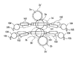
次に、本印刷機の胴回転駆動系の構成を説明すると、図2に示すように、固定動であるブランケット胴3aの軸13aにはギヤ(胴付設ギヤ)25が、移動動である版胴2a,2b及びブランケット胴3bの軸12a,12b,13bにはそれぞれギヤ(胴付設ギヤ)26a,26c,26bが固設されている。
そして、ギヤ25にはギヤ(動力伝達ギヤ)23が噛合し、ギヤ26a,26c,26bにはそれぞれギヤ(動力伝達ギヤ)24a,24c,24bが噛合している。
【0036】
また、移動胴2a,2b,3bの胴付設ギヤ26a,26c,26bに噛合する動力伝達ギヤ24a,24c,24bは、各移動胴2a,2b,3bを枢支するピボット14a,14c,14bと同心上に設けられている。ただし、動力伝達ギヤ24a,24c,24bはピボット14a,14c,14bとは無関係に回転する。
【0037】
また、動力伝達ギヤ24a,23,24b,24cは隣接するもの同士が互いに噛合した四連ギヤとして構成されている。
このような動力伝達ギヤ24a,23,24b,24cのひとつ(ここでは、位置を固定されたブランケット胴3aに対応する動力伝達ギヤ23の軸22)に、版胴2a,2b及びブランケット胴3a,3bを回転駆動するための駆動用モータ21が接続されており、駆動用モータ21が回転すると、ブランケット胴3aが動力伝達ギヤ23を介して回転駆動され、版胴2aは動力伝達ギヤ24aを介して回転駆動され、版胴2bは動力伝達ギヤ24cを介して回転駆動され、ブランケット胴3bが動力伝達ギヤ24bを介して回転駆動されるようになっている。
【0038】
本発明の一実施形態にかかるバリアブルカットオフ印刷機は上述のように構成されているので、カットオフ長さを変更する際には、各メカロック17の固定を解除して、各エアシリンダ16を作動させて、移動胴である版胴2a,2b及びブランケット胴3bを脱胴し、版胴2a,2b及びブランケット胴3a,3bをカットオフ長さに応じた外径のもの(符号2a´,2b´,3a´,3b´参照)に変更して、隣接する各胴2a´,3a´,3b´,2b´が接触するように、各エアシリンダ16を作動させる。
【0039】
この結果、ウェブ1のパス位置は変わる(符号1´参照)ものの、各移動胴2a´,2b´,3b´はカットオフ長さに応じて一意的に位置が決まり、ブランケット胴3a´,3b´のニップ点(原点)も決定するので、原点位置調整は不要になる。
このとき、各エアシリンダ16を、レギュレータにより流体圧を精密調整可能なものとして、流体圧シリンダの流体圧を予め較正しておけば、この流体圧シリンダの流体圧によって印圧を設定することができる。
【0040】
この後、各メカロック17を作動させれば、移動胴の固定を確実に行なえる。
なお、各メカロック17はエア圧を利用して発生する摩擦力で各シリンダを固定するので、各シリンダの固定及び固定解除を容易に且つ確実に行なうことができる。
このメカロック17についても、エア以外の流体圧(例えば油圧)を用いたり、他の締め付け力を用いたりしてもよい。
【0041】
また、各胴2a,2b,3a,3bの回転駆動にあたっては、1つの駆動用モータによって、4つの胴を駆動することができ、しかも、カットオフ長さを変更する場合には、各移動胴2a,3a,3bをピボット14回りに揺動させるとこれと共に胴付設ギヤ25,26a,26b,26cも揺動するが、動力伝達ギヤ23,24a,24b,24cがピボット17と同心上に設けてあるため、胴付設ギヤ25,26a,26b,26cは動力伝達ギヤ23,24a,24b,24cと噛合した状態を保って揺動する。このため、カットオフ長さを変更されても、各動力伝達ギヤ及び各胴付設ギヤを通じて1つの駆動用モータによって、4つの胴を駆動することができる。
【0042】
また、4つの胴付設ギヤ25,26a,26b,26cを互いに同一歯数のギヤとし、4つの動力伝達ギヤ23,24a,24b,24cを互いに同一歯数のギヤとしているので、同一ギヤを用いて低コストに且つ確実に各胴を同期回転させることができる。
さらに、各胴付設ギヤ25,26a,26b,26cの刃先円の径を、最小カットオフ長さに応じた各胴の外径よりも小さく設定すれば、カットオフ調整範囲での胴付設ギヤの干渉を防止することができる。
【0043】
また、各動力伝達ギヤ25,26a,26b,26cの刃先円の径を、カットオフ長さの調整範囲の中間値に応じた各胴の外径とほぼ等しく設定することが好ましく、これにより、カットオフ調整範囲を広く設定しやすくなる。
【0044】
[その他]
以上、本発明の実施形態について説明したが、本発明は上述の実施形態に限定されるものではなく、本発明の趣旨を逸脱しない範囲内で種々変形して実施することができる。
例えば、上記実施形態を互いに組み合わせて実施しても良いことは言うまでもない。つまり、各胴の回転駆動系のみを適用したり、各胴の移動系のみを適用したりしてもよく、さらに、回転駆動系の一部や胴移動系の一部のみを適用しても良い。
【0045】
【発明の効果】
以上説明したように、本発明のバリアブルカットオフ印刷機(請求項1)によれば、第1,第2のブランケット胴のうちいずれかの胴が軸位置を固定された固定胴として構成され、残りの3つの胴が該固定胴に対して離接するように軸位置を移動可能にされた移動胴として構成されており、各移動胴がそれぞれ所定の軌道で移動するので、第1,第2のブランケット胴及び第1,第2の版胴の各外径が設定されれば、少なくとも、第1,第2のブランケット胴によるニップ点(原点)は幾何学的に1つに決定することになり、原点位置調整は不要になる。
【0046】
該駆動手段として、流体圧シリンダを用いれば、移動胴を位置決めする場合、固定胴に隣接する移動胴については、流体圧シリンダを作動させて固定胴に追い込むことによって行なうことができる。さらにかかる流体圧シリンダを、レギュレータにより流体圧を精密調整可能なものとすれば、流体圧シリンダの流体圧を予め較正しておき、この流体圧シリンダの流体圧によって印圧を設定することができる(請求項2)。
【0047】
該固定手段として、流体圧を利用して発生する摩擦力で該駆動手段の可動部又は該支持部材を固定するメカニカルロック機構を用いれば、移動胴の固定及び固定解除を容易に且つ確実に行なうことができる。したがって、流体圧シリンダの流体圧によって印圧を設定した場合、確実にこの設定状態に保持することができる(請求項3)。
【0048】
該案内手段として、各支持部材をそれぞれ揺動可能に支持するピボットを用いれば、各胴を移動可能にシンプルに保持することができる(請求項4)。
案内手段としてピボットを用いる構成に加えて、固定胴及び移動胴のそれぞれに各胴と一体に回転する胴付設ギヤを設け、固定胴及び移動胴毎のそれぞれに上記の各胴付設ギヤと噛合する動力伝達ギヤを設けて、動力伝達ギヤのうち上記の各移動胴に設けられたものは移動胴を支持する該ピボットと同心上に配置するとともに、各動力伝達ギヤを四連ギヤとして構成し、これらの動力伝達ギヤのうちの固定胴に設けられた動力伝達ギヤの回転軸に、各胴を回転駆動するための駆動用モータを接続すれば、1つの駆動用モータによって、4つの胴を駆動することができる。しかも、カットオフ長さを変更する場合には、各移動胴をピボット回りに揺動させるとこれと共に胴付設ギヤも揺動するが、動力伝達ギヤがピボットと同心上に設けてあるため、胴付設ギヤは動力伝達ギヤと噛合した状態を保って揺動するため、カットオフ長さを変更されても、各動力伝達ギヤ及び各胴付設ギヤを通じて1つの駆動用モータによって、4つの胴を駆動することができる(請求項6)。
【0049】
また、本発明のバリアブルカットオフ印刷機(請求項7)によれば、第1,第2のブランケット胴及び第1,第2の版胴のうちいずれかの胴が軸位置を固定された固定胴として構成され、残りの3つの胴が該固定胴に対して離接するように軸位置を移動可能にピボットで支持された移動胴として構成されるとともに、固定胴及び移動胴にそれぞれ設けられて各胴と一体に回転する胴付設ギヤと、各胴毎に設けられて上記の各胴付設ギヤと噛合する動力伝達ギヤとをそなえ、上記の各動力伝達ギヤは四連ギヤとして構成されるとともに該動力伝達ギヤのうち上記の各移動胴に設けられたものは該移動胴を支持する該ピボットと同心上に配置され、上記動力伝達ギヤのうちの固定胴に設けられた動力伝達ギヤの回転軸に、上記の各胴を回転駆動する駆動用モータが接続されているので、1つの駆動用モータによって、4つの胴を駆動することができ、しかも、カットオフ長さを変更する場合には、各移動胴をピボット回りに揺動させるとこれと共に胴付設ギヤも揺動するが、動力伝達ギヤがピボットと同心上に設けてあるため、胴付設ギヤは動力伝達ギヤと噛合した状態を保って揺動するため、カットオフ長さを変更されても、各動力伝達ギヤ及び各胴付設ギヤを通じて1つの駆動用モータによって、4つの胴を駆動することができる。
【0050】
4つの胴付設ギヤを互いに同一歯数のギヤとし、4つの動力伝達ギヤを互いに同一歯数のギヤとすれば、同一ギヤを用いて低コストに且つ確実に各胴を同期回転させることができる(請求項8)。
さらに、各胴付設ギヤの刃先円の径を、最小カットオフ長さに応じた各胴の外径よりも小さく設定すれば、カットオフ調整範囲での胴付設ギヤの干渉を防止することができる(請求項9)。
【0051】
また、各動力伝達ギヤの刃先円の径を、カットオフ長さの調整範囲の中間値に応じた各胴の外径とほぼ等しく設定すれば、カットオフ調整範囲を広く設定しやすくなる(請求項10)。
【図面の簡単な説明】
【図1】本発明の一実施形態にかかるバリアブルカットオフ印刷機の胴移動系の構成を説明する印刷胴の模式的側面図である。
【図2】本発明の一実施形態にかかるバリアブルカットオフ印刷機の胴回転駆動系の構成を説明する印刷胴の模式的側面図である。
【図3】本発明の一実施形態にかかるバリアブルカットオフ印刷機の胴位置の固定手段を説明する模式的断面図であり、(a)は固定状態を示し、(b)は固定解除状態を示す。
【図4】バリアブルカットオフ印刷機を説明する印刷機の要部の模式的側面図である。
【図5】従来のバリアブルカットオフ印刷機の胴移動系の構成を説明する印刷胴の模式的側面図である。
【図6】従来のバリアブルカットオフ印刷機の胴回転駆動系の構成を説明する印刷胴の模式的側面図である。
【符号の説明】
1,1´ ウェブ
2,2a,2b,2a´,2b´ 版胴
3,3a,3b,3a´,3b´ ブランケット胴
4,4a,4b 刷版
5,5a,5b ブランケット
12a,12b,13a,13b 軸
14,14a,14b,14c ピボット
15,15a,15b,15c 可動軸受ブロック(支持部材)
16,16a,16b,16c エアシリンダ(流体圧シリンダ)
17,17a,17b,17c メカニカルストッパ(メカストッパ)
18a ピストンロッド
18b ケーシング
18c テーパ状ブレーキピストン
18d スプリング
18e ローラ
18f ブレーキアーム
18g ブレーキシュー
18h テーパ面
18j エア給排口
18k エア室
21 駆動用モータ
22 軸
23,24a,24c,24b ギヤ(動力伝達ギヤ)
25,26a,26c,26b ギヤ(胴付設ギヤ)[0001]
TECHNICAL FIELD OF THE INVENTION
The present invention is a rotary printing press that performs printing on both sides of a web so as to sandwich a running web, and has a cutoff length by replacing each blanket cylinder or each plate cylinder with a different outer diameter. The present invention relates to a variable cut-off printing machine that can change the printing.
[0002]
[Prior art]
In order to perform printing on both sides of the web (continuous paper), the rotary printing press is provided with
[0003]
In such a rotary printing machine, when the printing length is changed (that is, the cutoff length of the web is changed), the circumferential length of the printing plate or blanket is changed, that is, the printing cylinder (the plate cylinder 2 and the blanket cylinder) is changed. In some cases, it is required to change the diameter of 3). In response to such a request, generally, the printing cylinders 2, 3, the printing plate 4, and the blanket 5 are all replaced with one another, and as shown by the solid line and the dashed line in FIG. It cannot be handled without changing the support position.
[0004]
Therefore, various techniques have been proposed for moving the shaft support positions (also simply referred to as shaft positions) of the printing cylinders 2 and 3 (for example, see Patent Documents 1 and 2).
In the technique according to Patent Literature 1, as shown in FIG. 5, the axial positions of the
[0005]
For example, when each
[0006]
Each of the
[0007]
In the technique according to Patent Literature 2, the
Even when the shaft support position of each
[0008]
Therefore, in the case of the technique according to Patent Document 2, as shown in FIG. 6, each of the
[0009]
Further, a gear mechanism is interposed between the motor and each of the
[0010]
[Patent Document 1]
JP 2001-514105 A
[Patent Document 2]
JP 2001-62989 A
[Patent Document 3]
Japanese Patent Publication No. 10-503444
[0011]
[Problems to be solved by the invention]
In a variable cut-off printing press, it is necessary to adjust the position of the printing cylinder in accordance with the outer diameter of the printing cylinder and to adjust the origin of the printing cylinder every time the cut-off is changed. That is, it is necessary to adjust the positions of the
[0012]
However, in the techniques of Patent Literatures 1 and 2, since the position of both the
[0013]
In addition, it is necessary to adjust the printing pressure so that a predetermined printing pressure is obtained from the origin adjustment position, and the printing pressure needs to be adjusted even when the paper pressure changes significantly. Is not easy to adjust.
Further, since the printing pressure is adjusted by the amount of drive of the printing cylinder, individual differences occur due to mechanical play or elastic deformation, so that quantitative management cannot be performed.
[0014]
As for the drive system of each printing cylinder of the variable cut-off printing press, if a single motor system is used as shown in FIG. 6, four motors are required for one unit, which increases the cost and increases the size of a large control panel. It becomes necessary to install.
Further, since the inertial mass of the motor itself is smaller than the mass of each printing cylinder, the motor is susceptible to disturbances such as generating a calling shock and is liable to cause rotation fluctuation.
[0015]
Further, as in the technique of Patent Document 3, a mechanical drive system in which a gear is interposed between a motor and a printing cylinder is employed, and such a motor and a gear mechanism are separately provided for each shaft support position of the printing cylinder. In this case, the drive system becomes extremely complicated, and when changing gears at the time of cut-off, a great deal of switching time and labor is required.
[0016]
The present invention has been devised in view of such a problem, and a first object of the present invention is to provide a variable cut-off printing machine capable of easily adjusting the origin position of a printing cylinder every time the cut-off is changed. That is.
A second object of the present invention is to provide a variable cut-off printing machine which can easily adjust the printing pressure.
Further, a third object of the present invention is to provide a variable cut-off printing machine which has a simple configuration, is less likely to cause rotational fluctuations, and can appropriately rotate each printing cylinder.
[0017]
[Means for Solving the Problems]
In order to achieve the above object, a variable cut-off printing press according to the present invention (Claim 1) is provided with a blanket on the outer periphery and a blanket provided on each side of a running web so as to sandwich the running web. A first plate cylinder equipped with a blanket cylinder, a printing plate contacting the blanket of the first blanket cylinder on the outer periphery, and a first plate cylinder equipped with a printing plate contacting the blanket of the second blanket cylinder on the outer periphery. A variable cut having a second plate cylinder and a cut-off length that can be changed by changing the outer diameter of each of the first and second blanket cylinders and the first and second plate cylinders. An off-press machine, wherein one of the first and second blanket cylinders is configured as a fixed cylinder having a fixed axial position, and the remaining three cylinders are separated from and contacted with the fixed cylinder. Move the axis position Guide means configured to guide the movement of a support member that supports each of the moving cylinders so that each of the moving cylinders moves in a predetermined trajectory. A drive means for moving the moving cylinder through the support member so as to move away from and to the fixed cylinder along the predetermined track, and a fixing means for mechanically fixing the position of each of the moving cylinders are provided. It is characterized by:
[0018]
It is preferable that the driving means is a fluid pressure cylinder whose fluid pressure can be precisely adjusted by a regulator (claim 2).
The fixing means is preferably a mechanical lock mechanism for fixing the movable portion of the driving means or the support member by a frictional force generated using a fluid pressure (claim 3).
It is preferable that the guide means is a pivot that supports each of the support members so as to be swingable (claim 4).
[0019]
It is preferable that the guide means is a linear guide that guides each of the support members so as to be slidable (claim 5).
Further, a body-provided gear provided on each of the fixed cylinder and the movable body and rotating integrally with each body, and a power transmission provided on each of the fixed body and the movable body and engaged with each of the body-provided gears Gears, each of the power transmission gears is configured as a quadruple gear, and among the power transmission gears, those provided on each of the moving cylinders are arranged concentrically with the pivots that support the moving cylinders. Preferably, a driving motor for rotating each of the cylinders is connected to a rotation shaft of a power transmission gear provided on a fixed cylinder of the power transmission gears.
[0020]
In addition, the variable cut-off printing press of the present invention (Claim 7) includes first and second blanket cylinders each provided on both sides of a running web and provided with a blanket on an outer periphery thereof, and A first plate cylinder peripherally equipped with a printing plate contacting the blanket of a first blanket cylinder, and a second plate cylinder peripherally equipped with a printing plate contacting the blanket of the second blanket cylinder. A variable cutoff printing press having a cutoff length that can be changed by changing the outer diameter of each of the first and second blanket cylinders and the first and second plate cylinders. One of the first and second blanket cylinders and the first and second plate cylinders is configured as a fixed cylinder having a fixed axial position, and the remaining three cylinders are fixed to the fixed cylinder. The axial position so that A barrel-mounted gear that is movably supported by a pivot and that is provided on the fixed barrel and the movable barrel, respectively, and that rotates together with each barrel. Each of the power transmission gears is configured as a quadruple gear, and one of the power transmission gears provided on each of the moving cylinders is the moving cylinder. A driving motor for rotating each of the cylinders is connected to a rotation shaft of a power transmission gear provided on a fixed cylinder of the power transmission gears, which is arranged concentrically with the pivot for supporting the body. It is characterized by.
[0021]
Preferably, the four body-attached gears have the same number of teeth, and the four power transmission gears preferably have the same number of teeth.
It is preferable that the diameter of the cutting edge circle of each of the body-attached gears is set smaller than the outer diameter of each of the cylinders according to the minimum cutoff length (claim 9).
It is preferable that the diameter of the cutting edge circle of each of the power transmission gears is set to be substantially equal to the outer diameter of each of the cylinders according to the intermediate value of the adjustment range of the cutoff length.
[0022]
BEST MODE FOR CARRYING OUT THE INVENTION
Hereinafter, embodiments of the present invention will be described with reference to the drawings.
1 to 3 show a variable cut-off printing press according to an embodiment of the present invention. FIG. 1 is a schematic side view of a printing cylinder illustrating a configuration of a cylinder moving system, and FIG. FIG. 3 is a schematic side view of a printing cylinder illustrating a configuration of a driving system, and FIG. 3 is a schematic cross-sectional view illustrating fixing means of the cylinder position.
[0023]
As shown in FIG. 1, the variable cutoff printing press according to the present embodiment is a rotary-type double-sided printing press that performs printing on both sides of a web (continuous paper). The lower surface) is provided with
[0024]
A printing plate (not shown) is provided on the surface of each plate cylinder 2, and a blanket is provided on the surface of each blanket cylinder 3.
Of these
[0025]
That is, the
[0026]
One end of each
[0027]
The
The pivot 14 functions as guide means for guiding each movable bearing block 15 so as to swing around the pivot axis. The air cylinder 16 functions as a driving unit that rotates (swings) each movable bearing block 15 around the pivot axis by expanding and contracting.
[0028]
Here, the pivot 14 is used as the guide means, but other guide means such as a slide guide (for example, a linear slide guide) for sliding each movable bearing block 15 may be applied. However, in the configuration in which each movable bearing block 15 is swung around the pivot 14, the support of each movable bearing block 15 can be simplified, and each movable bearing block 15 can be easily and smoothly moved. Stable driving can be performed only by providing one driving means at the end of the movable bearing block 15.
[0029]
Although the air cylinder 16 is used as the driving means here, a fluid pressure cylinder such as a hydraulic cylinder can be widely applied. Of course, other than a fluid pressure cylinder such as an electric motor may be used as the driving means. However, in the case of the air cylinder 16, there is an advantage that the handling of piping and the like from the fluid pressure source (air pressure source) is easy and the handling is easy.
[0030]
As the
[0031]
One space defined by the tapered
[0032]
A tapered tapered
As shown in FIG. 3B, when the air in the
[0033]
Conversely, as shown in FIG. 3A, when air is supplied into the
[0034]
The relationship between the rotation center A of the
[0035]
Next, the configuration of the cylinder rotation drive system of the printing press will be described. As shown in FIG. 2, a gear (cylinder attached gear) 25 is provided on a
A gear (power transmission gear) 23 meshes with the
[0036]
The power transmission gears 24a, 24c, 24b meshing with the body-attached
[0037]
The power transmission gears 24a, 23, 24b, 24c are configured as quadruple gears in which adjacent ones mesh with each other.
One of the power transmission gears 24a, 23, 24b, 24c (here, the
[0038]
Since the variable cutoff printing press according to one embodiment of the present invention is configured as described above, when changing the cutoff length, the fixing of each
[0039]
As a result, although the path position of the web 1 changes (see reference numeral 1 '), the position of each moving
At this time, if the air pressure of each air cylinder 16 can be precisely adjusted by a regulator and the fluid pressure of the fluid pressure cylinder is calibrated in advance, the printing pressure can be set by the fluid pressure of the fluid pressure cylinder. it can.
[0040]
Thereafter, when the respective
Since each
Also for the
[0041]
In rotating the
[0042]
Further, since the four body-attached
Furthermore, if the diameter of the cutting edge circle of each body-mounted
[0043]
Further, it is preferable that the diameter of the cutting edge circle of each of the power transmission gears 25, 26a, 26b, 26c is set to be substantially equal to the outer diameter of each cylinder corresponding to an intermediate value of the adjustment range of the cutoff length. It becomes easy to set a wide cutoff adjustment range.
[0044]
[Others]
Although the embodiments of the present invention have been described above, the present invention is not limited to the above-described embodiments, and can be variously modified and implemented without departing from the gist of the present invention.
For example, it goes without saying that the above embodiments may be implemented in combination with each other. In other words, only the rotation drive system of each body may be applied, or only the movement system of each body may be applied, and further, only a part of the rotation drive system or a part of the body movement system may be applied. good.
[0045]
【The invention's effect】
As described above, according to the variable cut-off printing press of the present invention (claim 1), one of the first and second blanket cylinders is configured as a fixed cylinder having a fixed axial position, The remaining three cylinders are configured as movable cylinders whose axial positions can be moved so as to move away from and to the fixed cylinder. Each of the movable cylinders moves in a predetermined trajectory. If the outer diameters of the blanket cylinder and the first and second plate cylinders are set, at least the nip point (origin) of the first and second blanket cylinders is geometrically determined to be one. No need to adjust the home position.
[0046]
If a hydraulic cylinder is used as the driving means, the positioning of the moving cylinder can be performed by moving the moving cylinder adjacent to the fixed cylinder to operate the hydraulic cylinder to drive into the fixed cylinder. Further, if such a fluid pressure cylinder is capable of precisely adjusting the fluid pressure by a regulator, the fluid pressure of the fluid pressure cylinder can be calibrated in advance, and the printing pressure can be set by the fluid pressure of the fluid pressure cylinder. (Claim 2).
[0047]
If a mechanical lock mechanism for fixing the movable part of the driving means or the supporting member by a frictional force generated by using a fluid pressure is used as the fixing means, the moving cylinder can be easily and reliably fixed and released. be able to. Therefore, when the printing pressure is set by the fluid pressure of the fluid pressure cylinder, it is possible to surely maintain the setting state (claim 3).
[0048]
If a pivot is used as the guide means for swingably supporting each support member, each body can be simply and movably held (claim 4).
In addition to the configuration using a pivot as the guide means, a body-provided gear that rotates integrally with each of the fixed body and the movable body is provided on each of the fixed body and the movable body, and each of the fixed body and the movable body engages with each of the body-provided gears described above. A power transmission gear is provided, and among the power transmission gears, those provided on each of the moving cylinders are arranged concentrically with the pivot supporting the moving cylinder, and each power transmission gear is configured as a quadruple gear, If a driving motor for rotating each of the power transmission gears is connected to the rotation shaft of the power transmission gear provided on the fixed cylinder among these power transmission gears, the four drums are driven by one driving motor. can do. In addition, when the cutoff length is changed, when the moving cylinders are pivoted around the pivot, the gear attached to the cylinder is also pivoted, but the power transmission gear is provided concentrically with the pivot. Since the attached gears swing while maintaining the meshed state with the power transmission gears, even if the cutoff length is changed, the four barrels are driven by one drive motor through each power transmission gear and each barrel attached gear. (Claim 6).
[0049]
According to the variable cut-off printing press of the present invention, any one of the first and second blanket cylinders and the first and second plate cylinders has a fixed axial position. The remaining three cylinders are configured as movable cylinders supported by pivots so that the remaining three cylinders can move in the axial position so as to move away from and fixed to the fixed cylinder, and are provided on the fixed cylinder and the movable cylinder, respectively. A body-provided gear that rotates integrally with each body, and a power transmission gear that is provided for each body and meshes with each of the body-provided gears. Among the power transmission gears, those provided on each of the moving cylinders are arranged concentrically with the pivots that support the moving cylinders, and the rotation of the power transmission gears provided on the fixed cylinder of the power transmission gears Each of the above cylinders is rotationally driven Since the driving motors are connected, four cylinders can be driven by one driving motor, and when changing the cutoff length, each moving cylinder is swung around the pivot. With this, the gear attached to the body also swings, but since the power transmission gear is provided concentrically with the pivot, the gear attached to the body swings while maintaining the meshed state with the power transmission gear, so the cutoff length is Even if changed, the four cylinders can be driven by one driving motor through each power transmission gear and each trunk attached gear.
[0050]
If the four body-attached gears are gears having the same number of teeth and the four power transmission gears are gears having the same number of teeth, the same gears can be used to reliably and synchronously rotate the respective bodies at low cost. (Claim 8).
Furthermore, if the diameter of the cutting edge circle of each body-mounted gear is set smaller than the outer diameter of each body corresponding to the minimum cutoff length, interference of the body-mounted gear in the cutoff adjustment range can be prevented. (Claim 9).
[0051]
Further, if the diameter of the cutting edge circle of each power transmission gear is set substantially equal to the outer diameter of each cylinder corresponding to the intermediate value of the adjustment range of the cutoff length, it is easy to set the cutoff adjustment range wide. Item 10).
[Brief description of the drawings]
FIG. 1 is a schematic side view of a printing cylinder explaining a configuration of a cylinder moving system of a variable cutoff printing press according to an embodiment of the present invention.
FIG. 2 is a schematic side view of a printing cylinder illustrating a configuration of a cylinder rotation drive system of a variable cutoff printing press according to an embodiment of the present invention.
FIGS. 3A and 3B are schematic cross-sectional views illustrating a means for fixing the barrel position of the variable cut-off printing press according to one embodiment of the present invention, wherein FIG. 3A shows a fixed state, and FIG. Show.
FIG. 4 is a schematic side view of a main part of a printing press explaining a variable cut-off printing press.
FIG. 5 is a schematic side view of a printing cylinder illustrating a configuration of a cylinder moving system of a conventional variable cut-off printing press.
FIG. 6 is a schematic side view of a printing cylinder for explaining a configuration of a cylinder rotation drive system of a conventional variable cut-off printing press.
[Explanation of symbols]
1,1 'web
2, 2a, 2b, 2a ', 2b' plate cylinder
3,3a, 3b, 3a ', 3b' Blanket cylinder
4,4a, 4b printing plate
5,5a, 5b blanket
12a, 12b, 13a, 13b axis
14, 14a, 14b, 14c pivot
15, 15a, 15b, 15c Movable bearing block (support member)
16, 16a, 16b, 16c Air cylinder (fluid pressure cylinder)
17, 17a, 17b, 17c Mechanical stopper (mechanical stopper)
18a Piston rod
18b casing
18c tapered brake piston
18d spring
18e roller
18f brake arm
18g brake shoe
18h tapered surface
18j Air supply / discharge port
18k air chamber
21 Drive motor
22 axes
23, 24a, 24c, 24b Gear (power transmission gear)
25, 26a, 26c, 26b Gear (body-mounted gear)
Claims (10)
該第1のブランケット胴の該ブランケットに接触する刷版を外周に装備した第1の版胴、及び該第2のブランケット胴の該ブランケットに接触する刷版を外周に装備した第2の版胴とを有し、
上記の第1,第2のブランケット胴及び上記の第1,第2の版胴のそれぞれの外径を変更することによりカットオフ長さを変更しうるバリアブルカットオフ印刷機であって、
上記の第1,第2のブランケット胴のうちいずれかの胴が軸位置を固定された固定胴として構成され、残りの3つの胴が該固定胴に対して離接するように軸位置を移動可能にされた移動胴として構成されて、
上記の各移動胴がそれぞれ所定の軌道で移動するように、上記の各移動胴を軸支する支持部材の移動を案内する案内手段と、
上記の各移動胴が該所定の軌道に沿って該固定胴に対して離接するように該支持部材を通じて移動させる駆動手段と、
上記の各移動胴の位置を機械的に固定する固定手段とをそなえている
ことを特徴とする、バリアブルカットオフ印刷機。First and second blanket cylinders respectively provided on both sides of the running web so as to sandwich the running web and provided with blankets on the outer periphery;
A first plate cylinder equipped with a printing plate that contacts the blanket of the first blanket cylinder on the outer periphery, and a second plate cylinder equipped with a printing plate that contacts the blanket of the second blanket cylinder on the outer periphery And having
A variable cutoff printing press capable of changing a cutoff length by changing an outer diameter of each of the first and second blanket cylinders and the first and second plate cylinders,
Either of the first and second blanket cylinders is configured as a fixed cylinder having a fixed axial position, and the remaining three cylinders can move the axial position so as to be separated from and brought into contact with the fixed cylinder. Configured as a moving barrel
Guide means for guiding the movement of a support member that supports each of the moving cylinders so that each of the moving cylinders moves in a predetermined trajectory,
Driving means for moving through the support member such that each of the moving cylinders moves away from and to the fixed cylinder along the predetermined track;
A variable cutoff printing press, comprising: fixing means for mechanically fixing the positions of the moving cylinders.
ことを特徴とする、請求項1記載のバリアブルカットオフ印刷機。2. The variable cut-off printing press according to claim 1, wherein said driving means is a fluid pressure cylinder whose fluid pressure can be precisely adjusted by a regulator.
ことを特徴とする、請求項1又は2記載のバリアブルカットオフ印刷機。The variable cut-off according to claim 1, wherein the fixing unit is a mechanical lock mechanism that fixes the movable portion of the driving unit or the support member by a frictional force generated using a fluid pressure. Printer.
ことを特徴とする、請求項1〜3のいずれか1項に記載のバリアブルカットオフ印刷機。The variable cut-off printing press according to any one of claims 1 to 3, wherein the guide unit is a pivot that supports each of the support members in a swingable manner.
ことを特徴とする、請求項1〜3のいずれか1項に記載のバリアブルカットオフ印刷機。The variable cut-off printing press according to any one of claims 1 to 3, wherein the guide unit is a linear guide that guides each of the support members so as to be slidable.
上記の固定胴及び移動胴毎にそれぞれ設けられて上記の各胴付設ギヤと噛合する動力伝達ギヤとをそなえ、
上記の各動力伝達ギヤは四連ギヤとして構成されるとともに該動力伝達ギヤのうち上記の各移動胴に設けられたものは該移動胴を支持する該ピボットと同心上に配置され、
上記動力伝達ギヤのうちの固定胴に設けられた動力伝達ギヤの回転軸に、上記の各胴を回転駆動する駆動用モータが接続されている
ことを特徴とする、請求項4記載のバリアブルカットオフ印刷機。A body-mounted gear provided on the fixed body and the movable body, respectively, and integrally rotating with each body;
A power transmission gear provided with each of the fixed cylinder and the movable cylinder and meshing with each of the body-attached gears,
Each of the power transmission gears described above is configured as a quadruple gear, and among the power transmission gears, one provided on each of the moving cylinders is disposed concentrically with the pivot that supports the moving cylinder,
5. The variable cut according to claim 4, wherein a drive motor for rotating each of said cylinders is connected to a rotation shaft of a power transmission gear provided on a fixed cylinder of said power transmission gears. Off printing machine.
該第1のブランケット胴の該ブランケットに接触する刷版を外周に装備した第1の版胴、及び該第2のブランケット胴の該ブランケットに接触する刷版を外周に装備した第2の版胴とを有し、
上記の第1,第2のブランケット胴及び上記の第1,第2の版胴のそれぞれの外径を変更することによりカットオフ長さを変更しうるバリアブルカットオフ印刷機であって、
上記の第1,第2のブランケット胴及び第1,第2の版胴のうちいずれかの胴が軸位置を固定された固定胴として構成され、残りの3つの胴が該固定胴に対して離接するように軸位置を移動可能にピボットで支持された移動胴として構成されるとともに、
上記の固定胴及び移動胴にそれぞれ設けられて各胴と一体に回転する胴付設ギヤと、
上記の各胴毎に設けられて上記の各胴付設ギヤと噛合する動力伝達ギヤとをそなえ、
上記の各動力伝達ギヤは四連ギヤとして構成されるとともに、該動力伝達ギヤのうち上記の各移動胴に設けられたものは該移動胴を支持する該ピボットと同心上に配置され、
上記動力伝達ギヤのうちの固定胴に設けられた動力伝達ギヤの回転軸に、上記の各胴を回転駆動する駆動用モータが接続されている
ことを特徴とする、バリアブルカットオフ印刷機。First and second blanket cylinders respectively provided on both sides of the running web so as to sandwich the running web and provided with blankets on the outer periphery;
A first plate cylinder equipped with a printing plate that contacts the blanket of the first blanket cylinder on the outer periphery, and a second plate cylinder equipped with a printing plate that contacts the blanket of the second blanket cylinder on the outer periphery And having
A variable cutoff printing press capable of changing a cutoff length by changing an outer diameter of each of the first and second blanket cylinders and the first and second plate cylinders,
One of the first and second blanket cylinders and the first and second plate cylinders is configured as a fixed cylinder having a fixed axial position, and the remaining three cylinders are fixed with respect to the fixed cylinder. Along with being configured as a movable barrel supported by a pivot so that the axis position can be moved so as to move away
A body-mounted gear provided on the fixed body and the movable body, respectively, and integrally rotating with each body;
A power transmission gear that is provided for each of the cylinders and meshes with the gears provided with the cylinders;
Each of the power transmission gears described above is configured as a quadruple gear, and among the power transmission gears, one provided on each of the moving cylinders is disposed concentrically with the pivot that supports the moving cylinder,
A variable cut-off printing press, characterized in that a drive motor for rotating each of the cylinders is connected to a rotation shaft of a power transmission gear provided on a fixed cylinder of the power transmission gears.
ことを特徴とする、請求項6又は7記載のバリアブルカットオフ印刷機。8. The variable cutoff printing according to claim 6, wherein the four body-attached gears have the same number of teeth, and the four power transmission gears have the same number of teeth. Machine.
ことを特徴とする、請求項8記載のバリアブルカットオフ印刷機。9. The variable cut-off printing according to claim 8, wherein a diameter of a cutting edge circle of each of said body-mounted gears is set smaller than an outer diameter of each of said cylinders according to a minimum cut-off length. Machine.
ことを特徴とする、請求項8又は9記載のバリアブルカットオフ印刷機。The diameter of the cutting edge circle of each of the power transmission gears is set to be substantially equal to the outer diameter of each of the barrels according to an intermediate value of the cutoff length adjustment range. 9. The variable cutoff printing press according to 9.
Priority Applications (1)
| Application Number | Priority Date | Filing Date | Title |
|---|---|---|---|
| JP2002316803A JP2004148686A (en) | 2002-10-30 | 2002-10-30 | Variable cutoff printing machine |
Applications Claiming Priority (1)
| Application Number | Priority Date | Filing Date | Title |
|---|---|---|---|
| JP2002316803A JP2004148686A (en) | 2002-10-30 | 2002-10-30 | Variable cutoff printing machine |
Publications (1)
| Publication Number | Publication Date |
|---|---|
| JP2004148686A true JP2004148686A (en) | 2004-05-27 |
Family
ID=32460400
Family Applications (1)
| Application Number | Title | Priority Date | Filing Date |
|---|---|---|---|
| JP2002316803A Pending JP2004148686A (en) | 2002-10-30 | 2002-10-30 | Variable cutoff printing machine |
Country Status (1)
| Country | Link |
|---|---|
| JP (1) | JP2004148686A (en) |
Cited By (4)
| Publication number | Priority date | Publication date | Assignee | Title |
|---|---|---|---|---|
| JP2008536723A (en) * | 2005-04-21 | 2008-09-11 | ケーニツヒ ウント バウエル アクチエンゲゼルシヤフト | Method for adjusting printing unit and cylinder position |
| US7766450B2 (en) | 2005-09-16 | 2010-08-03 | Brother Kogyo Kabushiki Kaisha | Ink jet recording apparatus |
| JP4829291B2 (en) * | 2005-04-11 | 2011-12-07 | ゴス インターナショナル アメリカス インコーポレイテッド | Printing unit that enables automatic plating using a single motor drive |
| CN103612479A (en) * | 2006-02-02 | 2014-03-05 | 高斯国际美洲公司 | Reverse air flow web stabilizer |
-
2002
- 2002-10-30 JP JP2002316803A patent/JP2004148686A/en active Pending
Cited By (5)
| Publication number | Priority date | Publication date | Assignee | Title |
|---|---|---|---|---|
| JP4829291B2 (en) * | 2005-04-11 | 2011-12-07 | ゴス インターナショナル アメリカス インコーポレイテッド | Printing unit that enables automatic plating using a single motor drive |
| JP2008536723A (en) * | 2005-04-21 | 2008-09-11 | ケーニツヒ ウント バウエル アクチエンゲゼルシヤフト | Method for adjusting printing unit and cylinder position |
| US8261661B2 (en) | 2005-04-21 | 2012-09-11 | Koenig & Bauer Aktiengesellschaft | Printing press having at least one power controlled actuator for adjusting a print-on position |
| US7766450B2 (en) | 2005-09-16 | 2010-08-03 | Brother Kogyo Kabushiki Kaisha | Ink jet recording apparatus |
| CN103612479A (en) * | 2006-02-02 | 2014-03-05 | 高斯国际美洲公司 | Reverse air flow web stabilizer |
Similar Documents
| Publication | Publication Date | Title |
|---|---|---|
| JP5582195B2 (en) | Variable valve gear | |
| US7040225B2 (en) | Method for reducing vibrations in rotating components | |
| JP4816093B2 (en) | Friction transmission | |
| JP4370087B2 (en) | Support structure for offset printing machine blanket cylinder | |
| JP2003322181A (en) | Actuator for disc brake | |
| EP1882590A1 (en) | Register adjusting device of rotary body | |
| WO2016098819A1 (en) | Disc brake device | |
| US20070170299A1 (en) | Drives pertaining to a reel changer | |
| JP2009073193A (en) | Printer having pillow | |
| JP2005537197A5 (en) | ||
| JP2004148686A (en) | Variable cutoff printing machine | |
| JPS61213155A (en) | Device for controlling gripper in sheet rotary press | |
| KR20020077482A (en) | Device for operating a clutch | |
| JPH08300608A (en) | Adjusting device for rubber cylinder | |
| JP2779140B2 (en) | Adjuster for gripper mechanism of gripper | |
| JPWO2019058756A1 (en) | Web processing system and control method | |
| US6425326B1 (en) | Inking unit in a printing machine | |
| JP2005319805A (en) | Position sensor for direct driving device of cylinder in processing equipment | |
| JP2005145019A (en) | Printing pressure adjustment device for printing machine | |
| JP2009096200A (en) | Transfer cylinder between printing units of sheet-fed press | |
| JPH03204120A (en) | Pipe bending device | |
| US20070037683A1 (en) | Folding drum of a folder of a printing press | |
| EP1516728B1 (en) | Cylinder apparatus | |
| JP2803437B2 (en) | Rolling device for fillet roll machine | |
| JP2003305518A (en) | Pipe bending processing unit in pipe bending processing device |
Legal Events
| Date | Code | Title | Description |
|---|---|---|---|
| A621 | Written request for application examination |
Free format text: JAPANESE INTERMEDIATE CODE: A621 Effective date: 20051013 |
|
| A977 | Report on retrieval |
Free format text: JAPANESE INTERMEDIATE CODE: A971007 Effective date: 20070607 |
|
| A131 | Notification of reasons for refusal |
Free format text: JAPANESE INTERMEDIATE CODE: A131 Effective date: 20070612 |
|
| A521 | Written amendment |
Free format text: JAPANESE INTERMEDIATE CODE: A523 Effective date: 20070813 |
|
| A02 | Decision of refusal |
Free format text: JAPANESE INTERMEDIATE CODE: A02 Effective date: 20071113 |
|
| A521 | Written amendment |
Free format text: JAPANESE INTERMEDIATE CODE: A523 Effective date: 20080111 |
|
| A911 | Transfer of reconsideration by examiner before appeal (zenchi) |
Free format text: JAPANESE INTERMEDIATE CODE: A911 Effective date: 20080130 |
|
| A912 | Removal of reconsideration by examiner before appeal (zenchi) |
Free format text: JAPANESE INTERMEDIATE CODE: A912 Effective date: 20081010 |