JP2004147351A - Incorporated antenna for radio communication terminal - Google Patents
Incorporated antenna for radio communication terminal Download PDFInfo
- Publication number
- JP2004147351A JP2004147351A JP2004006153A JP2004006153A JP2004147351A JP 2004147351 A JP2004147351 A JP 2004147351A JP 2004006153 A JP2004006153 A JP 2004006153A JP 2004006153 A JP2004006153 A JP 2004006153A JP 2004147351 A JP2004147351 A JP 2004147351A
- Authority
- JP
- Japan
- Prior art keywords
- antenna
- wireless communication
- communication terminal
- built
- dipole antenna
- Prior art date
- Legal status (The legal status is an assumption and is not a legal conclusion. Google has not performed a legal analysis and makes no representation as to the accuracy of the status listed.)
- Pending
Links
Images


Landscapes
- Aerials With Secondary Devices (AREA)
- Support Of Aerials (AREA)
Abstract
Description
本発明は、無線通信端末に用いられる内蔵アンテナに関する。 << The present invention relates to a built-in antenna used for a wireless communication terminal.
近年、無線通信端末は、携帯性を向上させるために小型化が促進されている。これに伴い、無線通信端末に用いられる内蔵アンテナにも小型化が要求されている。これに対応するための従来の内蔵アンテナとして、板状逆Fアンテナが用いられるものがある。以下、従来の無線通信端末に用いられる内蔵アンテナについて説明する。 In recent years, miniaturization of wireless communication terminals has been promoted in order to improve portability. Along with this, miniaturization of built-in antennas used in wireless communication terminals is also required. As a conventional built-in antenna for coping with this, there is an antenna using a plate-shaped inverted-F antenna. Hereinafter, a built-in antenna used in a conventional wireless communication terminal will be described.
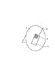
図93は、従来の無線通信端末に用いられる内蔵アンテナの構成を示す模式図である。なお、同図に示す各要素は、無線通信端末の筐体内に搭載されるものであるが、無線通信端末の全体図については、説明を簡単にするために省略する。同図に示すように、従来の無線通信端末には、一般に、地板1と板状逆Fアンテナ2とが設けられている。なお、X、Y及びZは、各々の座標軸を示す。
FIG. 93 is a schematic diagram showing a configuration of a built-in antenna used in a conventional wireless communication terminal. Although each element shown in FIG. 1 is mounted in the housing of the wireless communication terminal, an overall view of the wireless communication terminal is omitted for simplicity of description. As shown in FIG. 1, a conventional wireless communication terminal generally includes a ground plane 1 and a planar inverted-
また、上記従来の内蔵アンテナは、電波のマルチパスによる受信電界強度の変動に対処するダイバーシチアンテナとしても用いられる。図94は、従来の無線通信端末に用いられるダイバーシチアンテナの構成を示す模式図である。図94に示すように、上記従来の板状逆Fアンテナ2に加えて、外部アンテナとして、モノポールアンテナ3が設けられた構成となっている。内部アンテナである板状逆Fアンテナ2と外部アンテナであるモノポールアンテナ3の2つのアンテナによりダイバーシチ受信が行われて、安定した通信が行われる。
The above-mentioned conventional built-in antenna is also used as a diversity antenna for coping with fluctuations in received electric field strength due to multipath of radio waves. FIG. 94 is a schematic diagram showing a configuration of a diversity antenna used in a conventional wireless communication terminal. As shown in FIG. 94, a monopole antenna 3 is provided as an external antenna in addition to the conventional plate-shaped inverted
しかしながら、従来の無線通信端末に用いられる板状逆Fアンテナは、板状逆Fアンテナ2そのものがアンテナとして動作するというよりむしろ、地板1を励振する励振器として動作することになる。このため、地板1にアンテナ電流が流れることになり、アンテナとしては地板が支配的となる。この結果、従来の無線通信端末に用いられる板状逆Fアンテナ2は、上記無線通信端末のユーザの人体の影響により、利得が低下するという問題がある。
However, the plate-shaped inverted-F antenna used in the conventional wireless communication terminal operates not as the plate-shaped inverted-
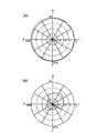
ここで、上記従来の無線通信端末に用いられる板状逆Fアンテナ2の受信特性の具体例について、図95(A)及び図95(B)を参照して説明する。図95(A)及び図95(B)は、従来の無線通信端末に用いられる板状逆Fアンテナの受信特性の実測値を示す図である。なお、ここでは、地板1の大きさを120×36mm、周波数を2180MHzとした。
Here, a specific example of the reception characteristics of the planar inverted-
まず、図95(A)は、従来の無線通信端末に用いられる板状逆Fアンテナ2の自由空間における水平面(X−Y面)の受信特性を示す図である。この場合、地板1がアンテナとして動作するので、図95(A)に示すように、板状逆Fアンテナ2は、ほぼ無指向性となっている。
First, FIG. 95 (A) is a diagram showing a reception characteristic of a planar inverted-
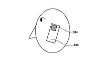
一方、図95(B)は、従来の無線通信端末に用いられる板状逆Fアンテナ2の通話時における水平面(X−Y面)の受信特性を示す図である。ここで、無線通信端末は、図96に示すような状態で用いられるとする。すなわち、板状逆Fアンテナ2及びモノポールアンテナ3が設けられた無線通信端末4は、図96に示すような状態で、ユーザ5による通話に用いられる。
On the other hand, FIG. 95 (B) is a diagram showing reception characteristics on a horizontal plane (XY plane) of the planar inverted
図95(B)から明らかなように、板状逆Fアンテナ2の利得は、通話時においては、低下している。このような、板状逆Fアンテナ2の利得の低下は、図95(A)と図95(B)を比較するに、人体の影響、例えば、ユーザの頭や手により電波が遮断される等の影響に起因するものであることは、明らかである。
利得 As is clear from FIG. 95 (B), the gain of the inverted inverted-
次いで、上記従来の無線通信端末に用いられる板状逆Fアンテナ2の放射特性の具体例について、図97(A)及び図97(B)を参照して説明する。図97(A)及び図97(B)は、従来の無線通信端末に用いられる板状逆Fアンテナの放射特性の実測値を示す図である。
Next, a specific example of the radiation characteristics of the planar inverted-
まず、図97(A)は、従来の無線通信端末に用いられる板状逆Fアンテナ2の自由空間における水平面(X−Y面)の放射特性を示す図である。この場合、地板1がアンテナとして動作するので、図97(A)に示すように、板状逆Fアンテナ2は、ほぼ無指向性となっている。
First, FIG. 97 (A) is a diagram showing radiation characteristics on a horizontal plane (XY plane) in free space of a plate-shaped inverted
一方、図97(B)は、従来の無線通信端末に用いられる板状逆Fアンテナ2の通話時における水平面(X−Y面)の放射特性を示す図である。ここで、無線通信端末は、図96に示すような状態で用いられるとする。図97(B)から明らかなように、板状逆Fアンテナ2の利得は、通話時においては、低下している。このような、板状逆Fアンテナ2の利得の低下は、図97(A)と図97(B)を比較するに、人体の影響、例えば、ユーザの頭や手により電波が遮断される等の影響に起因するものであることは、明らかである。
On the other hand, FIG. 97 (B) is a diagram showing radiation characteristics of a horizontal plane (XY plane) of the planar inverted
以上のように、上記従来の無線通信端末に用いられる板状逆Fアンテナ2においては、人体の影響により、利得が低下するという問題がある。
As described above, the plate-shaped inverted-
さらに、上記従来の無線通信端末に用いられるダイバーシチアンテナについても、板状逆Fアンテナ2が動作する場合には、上記と同様な問題が発生する。
{Circle around (4)} Also, the diversity antenna used in the above-described conventional wireless communication terminal has the same problem as described above when the plate-shaped inverted-
本発明は、かかる点に鑑みてなされたものであり、小型で、かつ、人体の影響が少ない高利得な無線通信端末用内蔵アンテナを提供することを目的とする。 The present invention has been made in view of the above circumstances, and an object of the present invention is to provide a high-gain built-in antenna for a wireless communication terminal which is small and has little influence on a human body.
本発明の無線通信端末用内蔵アンテナは、無線通信端末の筐体に内蔵され、板状の面を形成する接地導体と、前記接地導体に接続されたアンテナ素子を持つダイポールアンテナと、前記ダイポールアンテナと前記接地導体との間でインピーダンスを整合させ、かつ、平衡信号と不平衡信号との変換を行う平衡不平衡変換手段と、を有する構成を採る。 The built-in antenna for a wireless communication terminal according to the present invention is a dipole antenna built in a housing of the wireless communication terminal and forming a plate-like surface, a dipole antenna having an antenna element connected to the ground conductor, and the dipole antenna And a ground-unbalance conversion means for matching the impedance between the ground signal and the ground conductor, and converting between a balanced signal and an unbalanced signal.
本発明の無線通信端末用内蔵アンテナは、上記構成において、前記ダイポールアンテナは、棒状に形成されたアンテナ素子と矩形波状に形成されたアンテナ素子とによって構成され、前記棒状に形成されたアンテナ素子は、その軸方向が前記接地導体における前記板状の面の長手方向と平行になるように前記筐体の外部に設けられ、前記矩形波状に形成されたアンテナ素子は、その長手方向が前記接地導体における前記板状の面の長手方向と平行になるように前記筐体の内部に設けられている構成を採る。 In the wireless communication terminal built-in antenna of the present invention, in the above configuration, the dipole antenna is configured by a rod-shaped antenna element and a rectangular wave-shaped antenna element, and the rod-shaped antenna element is The antenna element is provided outside the housing so that an axial direction thereof is parallel to a longitudinal direction of the plate-shaped surface of the ground conductor, and the rectangular wave-shaped antenna element has a longitudinal direction of the ground conductor. In the case is provided inside the housing so as to be parallel to the longitudinal direction of the plate-like surface.
この構成によれば、平衡不平衡変換手段により、地板に流れるアンテナ電流を極力抑えることができるので、ダイポールアンテナの人体の影響に起因する利得劣化を抑えることができる。また、ダイポールアンテナを矩形波状のアンテナ素子により構成したので、無線通信端末用内蔵アンテナを小型化することができる。したがって、人体の影響の少ない高利得で小型の無線通信端末用内蔵アンテナを提供することができる。 According to this configuration, since the antenna current flowing to the ground plane can be suppressed as much as possible by the balance-unbalance conversion means, it is possible to suppress the gain deterioration due to the influence of the human body of the dipole antenna. Further, since the dipole antenna is formed by the rectangular wave-shaped antenna element, the size of the built-in antenna for the wireless communication terminal can be reduced. Therefore, it is possible to provide a small, high-gain built-in antenna for a wireless communication terminal that is less affected by the human body.
本発明の無線通信端末用内蔵アンテナは、上記構成において、前記ダイポールアンテナは、棒状に形成されたアンテナ素子と矩形波状に形成されたアンテナ素子とによって構成され、前記棒状に形成されたアンテナ素子は、その軸方向が前記接地導体における前記板状の面の長手方向と平行になるように前記筐体の外部に設けられ、前記矩形波状に形成されたアンテナ素子は、その長手方向が前記接地導体における前記板状の面の長手方向と垂直になるように前記筐体の内部に設けられている構成を採る。 In the wireless communication terminal built-in antenna of the present invention, in the above configuration, the dipole antenna is configured by a rod-shaped antenna element and a rectangular wave-shaped antenna element, and the rod-shaped antenna element is The antenna element is provided outside the housing so that an axial direction thereof is parallel to a longitudinal direction of the plate-shaped surface of the ground conductor, and the rectangular wave-shaped antenna element has a longitudinal direction of the ground conductor. In this case, a configuration is provided inside the housing so as to be perpendicular to the longitudinal direction of the plate-like surface in the above.
本発明の無線通信端末用内蔵アンテナは、上記構成において、前記ダイポールアンテナは、当該ダイポールアンテナを構成するアンテナ素子の給電端側が矩形波状に他端側が棒状にそれぞれ形成されており、前記アンテナ素子は、前記矩形波状に形成された部分の長手方向と前記棒状に形成された部分の軸方向とが直交するように折り曲げられ、前記矩形波状に形成された部分は、その長手方向が前記接地導体の長手方向と垂直に設けられ、かつ、前記棒状に形成された部分は前記筐体の外部に、前記矩形波状に形成された部分は前記筐体の内部にそれぞれ設けられている構成を採る。 The built-in antenna for a wireless communication terminal according to the present invention, in the above configuration, wherein the dipole antenna is formed such that a feeding end side of an antenna element constituting the dipole antenna is shaped like a rectangular wave and the other end is shaped like a rod, and the antenna element is The longitudinal direction of the rectangular wave-shaped portion and the axial direction of the rod-shaped portion are bent so as to be orthogonal to each other, and the rectangular wave-shaped portion has the longitudinal direction of the ground conductor. A configuration is provided in which the bar-shaped portion is provided outside the housing and the rectangular wave-shaped portion is provided inside the housing.
この構成によれば、ダイポールアンテナは、利得の劣化を抑えることができるとともに、アンテナ素子の長手方向と平行な垂直偏波と水平偏波のいずれも受信することができるので、垂直偏波と水平偏波のいずれが多い場合であっても、通信相手から送られる信号の偏波面と一致するので、受信利得を高くすることができる。 According to this configuration, the dipole antenna can suppress the deterioration of the gain and can receive both the vertical polarization and the horizontal polarization parallel to the longitudinal direction of the antenna element. Even if the number of polarizations is large, the reception gain can be increased because it matches the polarization plane of the signal sent from the communication partner.
本発明の無線通信端末用内蔵アンテナは、上記構成において、前記ダイポールアンテナは、前記棒状に形成されたアンテナ素子に代えて矩形波状に形成されたアンテナ素子を有する構成を採る。 内 蔵 The built-in antenna for a wireless communication terminal according to the present invention, in the above configuration, employs a configuration in which the dipole antenna has an antenna element formed in a rectangular wave shape instead of the rod-shaped antenna element.
本発明の無線通信端末用内蔵アンテナは、上記構成において、前記ダイポールアンテナは、前記棒状に形成されたアンテナ素子に代えて矩形波状に形成されたアンテナ素子を有する構成を採る。 内 蔵 The built-in antenna for a wireless communication terminal according to the present invention, in the above configuration, employs a configuration in which the dipole antenna has an antenna element formed in a rectangular wave shape instead of the rod-shaped antenna element.
本発明の無線通信端末用内蔵アンテナは、上記構成において、前記ダイポールアンテナは、前記アンテナ素子の前記棒状に形成された部分を矩形波状に形成してなる構成を採る。 内 蔵 The built-in antenna for a wireless communication terminal according to the present invention, in the above configuration, employs a configuration in which the dipole antenna is formed by forming the rod-shaped portion of the antenna element into a rectangular wave shape.
この構成によれば、ダイポールアンテナは、利得の劣化を抑えることができるとともに、外部アンテナを矩形波状にしたことから、小型化を図ることができる。 According to this configuration, the dipole antenna can suppress the deterioration of the gain, and can reduce the size because the external antenna has a rectangular wave shape.
本発明のダイバーシチアンテナは、上記記載の無線通信端末用内蔵アンテナを2つ用いて構成されている構成を採る。 ダ イ The diversity antenna of the present invention employs a configuration using two of the above-described built-in antennas for a wireless communication terminal.
本発明のダイバーシチアンテナは、上記記載の無線通信端末用内蔵アンテナと、矩形波状に形成された2つのアンテナ素子を持つダイポールアンテナとを有し、前記無線通信端末用内蔵アンテナ及び前記ダイポールアンテナによりダイバーシチ送受信を行う構成を採る。 A diversity antenna according to the present invention includes the above-described built-in antenna for a wireless communication terminal, and a dipole antenna having two antenna elements formed in a rectangular wave shape. Diversity is provided by the built-in antenna for a wireless communication terminal and the dipole antenna. A configuration for transmitting and receiving is adopted.
本発明のダイバーシチアンテナは、上記構成において、前記ダイポールアンテナは、矩形波状に形成された2つのアンテナ素子によって構成され、前記矩形波状に形成されたアンテナ素子は、いずれも、その長手方向が前記接地導体における前記板状の面の長手方向と平行になるように前記筐体の内部に設けられている構成を採る。 In the diversity antenna according to the present invention, in the above configuration, the dipole antenna is configured by two antenna elements formed in a rectangular wave shape, and each of the antenna elements formed in the rectangular wave shape has the ground direction set to the ground. A configuration is provided in the housing so as to be parallel to the longitudinal direction of the plate-shaped surface of the conductor.
本発明のダイバーシチアンテナは、上記構成において、前記ダイポールアンテナは、矩形波状に形成された2つのアンテナ素子によって構成され、前記矩形波状に形成されたアンテナ素子は、いずれも、その長手方向が前記接地導体における前記板状の面の長手方向と垂直になるように設けられている構成を採る。 In the diversity antenna according to the present invention, in the above configuration, the dipole antenna is configured by two antenna elements formed in a rectangular wave shape, and each of the antenna elements formed in the rectangular wave shape has the ground direction set to the ground. A configuration is adopted in which the conductor is provided so as to be perpendicular to the longitudinal direction of the plate-shaped surface.
本発明のダイバーシチアンテナは、上記構成において、前記ダイポールアンテナは、矩形波状に形成された2つのアンテナ素子によって構成され、前記矩形波状に形成された2つのアンテナ素子のうち第1のアンテナ素子は、その長手方向が前記接地導体における前記板状の面の長手方向と平行に設けられ、第2のアンテナ素子は、その長手方向が前記接地導体における前記板状の面の長手方向と垂直に設けられている構成を採る。 In the diversity antenna of the present invention, in the above configuration, the dipole antenna is configured by two antenna elements formed in a rectangular wave shape, and a first antenna element of the two antenna elements formed in the rectangular wave shape is: The longitudinal direction is provided parallel to the longitudinal direction of the plate-shaped surface of the ground conductor, and the second antenna element is provided such that the longitudinal direction is perpendicular to the longitudinal direction of the plate-shaped surface of the ground conductor. It adopts the configuration that is.
この構成によれば、ダイバーシチアンテナとして、上記構成のダイポールアンテナが用いられるので、人体の影響の少ない高利得な無線通信端末用ダイバーシチアンテナを提供することができる。 According to this configuration, since the dipole antenna having the above configuration is used as the diversity antenna, it is possible to provide a high-gain diversity antenna for a wireless communication terminal that is less affected by a human body.
本発明の無線通信端末用内蔵アンテナは、上記構成において、前記ダイポールアンテナは、棒状に形成されたアンテナ素子と矩形波状に形成されたアンテナ素子とによって構成され、前記棒状に形成されたアンテナ素子は、その軸方向が前記接地導体における前記板状の面の長手方向と垂直になるように前記筐体の内部に設けられ、前記矩形波状に形成されたアンテナ素子は、その長手方向が前記接地導体における前記板状の面の長手方向と平行になるように前記筐体の内部に設けられている構成を採る。 In the wireless communication terminal built-in antenna of the present invention, in the above configuration, the dipole antenna is configured by a rod-shaped antenna element and a rectangular wave-shaped antenna element, and the rod-shaped antenna element is The antenna element is provided inside the housing such that an axial direction thereof is perpendicular to a longitudinal direction of the plate-shaped surface of the ground conductor, and the antenna element formed in a rectangular wave shape has a longitudinal direction of the ground conductor. In the case is provided inside the housing so as to be parallel to the longitudinal direction of the plate-like surface.
本発明の無線通信端末用内蔵アンテナは、上記構成において、前記ダイポールアンテナは、棒状に形成されたアンテナ素子と矩形波状に形成されたアンテナ素子とによって構成され、前記棒状に形成されたアンテナ素子は、その軸方向が前記接地導体における前記板状の面の長手方向と平行になるように前記筐体の内部に設けられ、前記矩形波状に形成されたアンテナ素子は、その長手方向が前記接地導体における前記板状の面の長手方向と垂直になるように前記筐体の内部に設けられている構成を採る。 In the wireless communication terminal built-in antenna of the present invention, in the above configuration, the dipole antenna is configured by a rod-shaped antenna element and a rectangular wave-shaped antenna element, and the rod-shaped antenna element is The antenna element is provided inside the housing such that an axial direction thereof is parallel to a longitudinal direction of the plate-shaped surface of the ground conductor, and the rectangular wave-shaped antenna element has a longitudinal direction of the ground conductor. In this case, a configuration is provided inside the housing so as to be perpendicular to the longitudinal direction of the plate-like surface in the above.
本発明の無線通信端末用内蔵アンテナは、上記構成において、前記ダイポールアンテナは、当該ダイポールアンテナを構成するアンテナ素子の給電端側が棒状に他端側が矩形波状にそれぞれ形成されており、前記アンテナ素子は、前記矩形波状に形成された部分の長手方向と前記棒状に形成された部分の軸方向とが直交するように折り曲げられ、前記矩形波状に形成された部分は、その長手方向が前記接地導体の長手方向と平行に設けられ、かつ、前記棒状に形成された部分及び前記矩形波状に形成された部分は前記筐体の内部に設けられている構成を採る。 The built-in antenna for a wireless communication terminal according to the present invention, in the above configuration, wherein the dipole antenna is formed such that a feeding end side of an antenna element constituting the dipole antenna is shaped like a bar and the other end is shaped like a rectangular wave. The longitudinal direction of the rectangular wave-shaped portion and the axial direction of the rod-shaped portion are bent so as to be orthogonal to each other. A configuration is provided in which the bar-shaped portion and the rectangular wave-shaped portion are provided in parallel with the longitudinal direction and are provided inside the housing.
本発明の無線通信端末用内蔵アンテナは、上記構成において、前記ダイポールアンテナは、当該ダイポールアンテナを構成するアンテナ素子の給電端側が矩形波状に他端側が棒状にそれぞれ形成されており、前記アンテナ素子は、前記矩形波状に形成された部分の長手方向と前記棒状に形成された部分の軸方向とが直交するように折り曲げられ、前記矩形波状に構成された部分は、その長手方向が前記接地導体の長手方向と垂直に設けられ、かつ、前記棒状に形成された部分及び前記矩形波状に形成された部分は前記筐体の内部に設けられている構成を採る。 The built-in antenna for a wireless communication terminal according to the present invention, in the above configuration, wherein the dipole antenna is formed such that a feeding end side of an antenna element constituting the dipole antenna is formed in a rectangular wave shape and the other end side is formed in a rod shape. The longitudinal direction of the rectangular wave-shaped portion and the axial direction of the rod-shaped portion are bent so as to be orthogonal to each other, and the rectangular wave-shaped portion has the longitudinal direction of the ground conductor. The rod-shaped portion and the rectangular wave-shaped portion are provided perpendicular to the longitudinal direction and are provided inside the housing.
この構成によれば、ダイポールアンテナは、利得の劣化を抑えることができるとともに、前記ダイポールアンテナを構成するアンテナ素子の長手方向と平行な垂直偏波と水平偏波のいずれも受信することができるので、垂直偏波と水平偏波のいずれが多い場合であっても、通信相手から送られる信号の偏波面と一致するので、受信利得を高くすることができる。 According to this configuration, the dipole antenna can suppress the deterioration of the gain and can receive both the vertical polarization and the horizontal polarization parallel to the longitudinal direction of the antenna element forming the dipole antenna. Regardless of which of the vertical polarization and the horizontal polarization is large, the reception gain can be increased because it matches the polarization plane of the signal sent from the communication partner.
さらに、垂直偏波を主に棒状のアンテナ素子で受信し、水平偏波を主に矩形波状のアンテナ素子で受信することから、垂直偏波と水平偏波の偏波比を適宜変化させることができるので、アンテナの使用目的に応じた偏波比で受信することができる。 Furthermore, since the vertical polarization is mainly received by the rod-shaped antenna element and the horizontal polarization is mainly received by the rectangular antenna element, it is possible to appropriately change the polarization ratio between the vertical polarization and the horizontal polarization. Therefore, reception can be performed at a polarization ratio according to the purpose of use of the antenna.
本発明の無線通信端末用内蔵アンテナは、上記構成において、前記ダイポールアンテナは、矩形波状に形成されたアンテナ素子によって構成され、前記アンテナ素子は、その給電端と他端との間にインダクタンス素子が装荷されている構成を採る。 In the wireless communication terminal built-in antenna of the present invention, in the above-described configuration, the dipole antenna is configured by an antenna element formed in a rectangular wave shape, and the antenna element has an inductance element between its feeding end and the other end. Take the loaded configuration.
本発明の無線通信端末用内蔵アンテナは、上記構成において、前記ダイポールアンテナは、キャパシタンス素子が装荷された矩形波状の折り返しダイポールアンテナである構成を採る。 内 蔵 The built-in antenna for a wireless communication terminal according to the present invention, in the above configuration, employs a configuration in which the dipole antenna is a folded rectangular dipole antenna loaded with a capacitance element.
本発明の無線通信端末用内蔵アンテナは、上記構成において、前記ダイポールアンテナは、螺旋状に形成されたアンテナ素子によって構成され、前記アンテナ素子は、その給電端と他端との間にインダクタンス素子が装荷されている構成を採る。 In the wireless communication terminal built-in antenna of the present invention, in the above configuration, the dipole antenna is formed by a spirally formed antenna element, and the antenna element has an inductance element between a feeding end and the other end. Take the loaded configuration.
本発明の無線通信端末用内蔵アンテナは、上記構成において、前記ダイポールアンテナは、キャパシタンス素子が装荷された螺旋状の折り返しダイポールアンテナである構成を採る。 内 蔵 The built-in antenna for a wireless communication terminal according to the present invention, in the above configuration, employs a configuration in which the dipole antenna is a spiral folded dipole antenna loaded with a capacitance element.
本発明の無線通信端末用内蔵アンテナは、上記構成において、前記ダイポールアンテナは、矩形波状に形成されたアンテナ素子と、前記矩形波状に形成されたアンテナ素子と平行に配置された別の矩形波状のアンテナ素子とによって構成されている構成を採る。 The built-in antenna for a wireless communication terminal of the present invention, in the above configuration, wherein the dipole antenna has an antenna element formed in a rectangular waveform and another rectangular waveform arranged in parallel with the antenna element formed in the rectangular waveform. A configuration including an antenna element is employed.
本発明の無線通信端末用内蔵アンテナは、上記構成において、前記ダイポールアンテナは、螺旋状に形成されたアンテナ素子と、前記螺旋状に形成されたアンテナ素子と平行に配置された別の螺旋状のアンテナ素子とによって構成されている構成を採る。 In the wireless communication terminal built-in antenna of the present invention, in the above-described configuration, the dipole antenna has a helically formed antenna element and another helically formed antenna element arranged in parallel with the helically formed antenna element. A configuration including an antenna element is employed.
これらの構成によれば、利得の劣化を抑えることができるとともに、インピーダンスをステップアップさせることができ、インピーダンス整合を容易に行うことができる。また、ダイポールアンテナを二周波アンテナとして実現することができる。 According to these configurations, the deterioration of the gain can be suppressed, the impedance can be stepped up, and the impedance matching can be easily performed. Further, the dipole antenna can be realized as a two-frequency antenna.
本発明の無線通信端末用内蔵アンテナは、上記構成において、棒状に形成された第一の無給電素子をさらに有し、前記ダイポールアンテナは、棒状に形成された2つのアンテナ素子を同一直線上に配置して構成され、前記第一の無給電素子は、その軸方向が前記ダイポールアンテナを構成する前記棒状に形成されたアンテナ素子の軸方向と平行であり、かつ、当該第一の無給電素子と前記ダイポールアンテナを構成する前記棒状に形成されたアンテナ素子とによって形成される基準面が前記筐体の主面と直交するように設けられ、前記基準面に沿う方向であって前記筐体の主面と直交する方向に指向性が形成されている構成を採る。 The built-in antenna for a wireless communication terminal of the present invention, in the above configuration, further includes a first parasitic element formed in a rod shape, and the dipole antenna is configured such that the two antenna elements formed in a rod shape are on the same straight line. The first parasitic element is arranged and configured, and the axial direction thereof is parallel to the axial direction of the rod-shaped antenna element forming the dipole antenna, and the first parasitic element. And a reference surface formed by the rod-shaped antenna element constituting the dipole antenna is provided so as to be orthogonal to the main surface of the housing, and is a direction along the reference surface and A configuration in which directivity is formed in a direction orthogonal to the main surface is adopted.
この構成によれば、ダイポールアンテナの長さ、第一の無給電素子の長さ、及び、ダイポールアンテナと第一の無給電素子との間隔を適切に調整することにより、人体と逆方向の指向性を持つようにしたので、ダイポールアンテナの人体の影響による利得劣化を抑えることができる。また、平衡不平衡変換回路においてインピーダンスを適切に整合させることにより、地板に流れるアンテナ電流を極力抑えることができるので、ダイポールアンテナの利得劣化を抑えることができる。 According to this configuration, by appropriately adjusting the length of the dipole antenna, the length of the first parasitic element, and the interval between the dipole antenna and the first parasitic element, the directivity in the direction opposite to the human body is adjusted. Since it has the characteristic, it is possible to suppress the gain deterioration due to the influence of the human body of the dipole antenna. Further, by appropriately matching the impedance in the balanced-unbalanced conversion circuit, the antenna current flowing through the ground plane can be suppressed as much as possible, so that the gain deterioration of the dipole antenna can be suppressed.
本発明の無線通信端末用内蔵アンテナは、上記構成において、矩形波状に形成された第一の無給電素子をさらに有し、前記ダイポールアンテナは、矩形波状に形成された2つのアンテナ素子をその長手方向の中心線が同一直線上になるように配置して構成され、前記第一の無給電素子は、その長手方向が前記ダイポールアンテナを構成する前記矩形波状に形成されたアンテナ素子の長手方向と平行であり、かつ、当該第一の無給電素子と前記ダイポールアンテナを構成する前記矩形波状に形成されたアンテナ素子とによって形成される基準面が前記筐体の主面と直交するように設けられ、前記基準面に沿う方向であって前記筐体の主面と直交する方向に指向性が形成されている構成を採る。 The built-in antenna for a wireless communication terminal of the present invention, in the above configuration, further includes a first parasitic element formed in a rectangular wave shape, and the dipole antenna has two antenna elements formed in a rectangular wave shape. The first parasitic element is arranged so that the center line of the direction is on the same straight line, and the longitudinal direction of the first parasitic element is the longitudinal direction of the rectangular wave-shaped antenna element constituting the dipole antenna. Parallel, and a reference plane formed by the first parasitic element and the rectangular wave-shaped antenna element forming the dipole antenna is provided so as to be orthogonal to the main surface of the housing. The directivity is formed in a direction along the reference plane and perpendicular to the main surface of the housing.
本発明の無線通信端末用内蔵アンテナは、上記構成において、前記筐体の主面は、矩形状に形成されており、前記第一の無給電素子は、前記筐体の主面の長手方向に沿って設けられている構成を採る。 In the wireless communication terminal built-in antenna of the present invention, in the above configuration, the main surface of the housing is formed in a rectangular shape, and the first parasitic element is arranged in a longitudinal direction of the main surface of the housing. The structure provided along is adopted.
この構成によれば、人体の影響による利得劣化を抑えることができるとともに、受信の際には、軸方向と平行な垂直偏波を受信することができる。したがって、垂直偏波が多い場合には、アンテナの軸方向と偏波面が一致するので受信利得を高くすることができる。 According to this configuration, it is possible to suppress the gain deterioration due to the influence of the human body, and at the time of reception, it is possible to receive a vertically polarized wave parallel to the axial direction. Therefore, when there are many vertical polarizations, the axis of the antenna coincides with the polarization plane, so that the reception gain can be increased.
本発明の無線通信端末用内蔵アンテナは、上記構成において、前記筐体の主面は、矩形状に形成されており、前記第一の無給電素子は、前記筐体の主面の幅方向に沿って設けられている構成を採る。 In the wireless communication terminal built-in antenna of the present invention, in the above configuration, the main surface of the housing is formed in a rectangular shape, and the first parasitic element is arranged in a width direction of the main surface of the housing. The structure provided along is adopted.
この構成によれば、人体の影響による利得劣化を抑えることができるとともに、受信の際には、軸方向と平行な水平偏波を受信することができる。したがって、水平偏波が多い場合には、アンテナの軸方向と偏波面が一致するので受信利得を高くすることができる。 According to this configuration, it is possible to suppress the gain deterioration due to the influence of the human body, and to receive horizontal polarized waves parallel to the axial direction during reception. Therefore, when there is a large amount of horizontal polarization, the reception direction can be increased because the axial direction of the antenna coincides with the plane of polarization.
本発明の無線通信端末用内蔵アンテナは、上記構成において、前記筐体の主面は、矩形状に形成されており、前記第一の無給電素子は、前記基準面に沿って折り曲げられ、折り曲げ後の一方の直線部分は、前記筐体の主面の長手方向に沿って設けられ、折り曲げ後の他方の直線部分は、前記筐体の主面の幅方向に沿って設けられている構成を採る。 In the wireless communication terminal built-in antenna of the present invention, in the above configuration, a main surface of the housing is formed in a rectangular shape, and the first parasitic element is bent along the reference plane, and is bent. The rear one linear portion is provided along the longitudinal direction of the main surface of the housing, and the other linear portion after bending is provided along the width direction of the main surface of the housing. take.
本発明の無線通信端末用内蔵アンテナは、上記構成において、前記筐体の主面は、矩形状に形成されており、前記第一の無給電素子は、前記基準面に沿ってコの字形に折り曲げられ、折り曲げ後の直線部分のうち、端部を含む直線部分は、前記筐体の主面の長手方向に沿って設けられ、端部を含まない直線部分は、前記筐体の主面の幅方向に沿って設けられている構成を採る。 In the wireless communication terminal built-in antenna of the present invention, in the above configuration, the main surface of the housing is formed in a rectangular shape, and the first parasitic element has a U shape along the reference surface. Among the straight portions that are bent, the straight portion including the end is provided along the longitudinal direction of the main surface of the housing, and the straight portion that does not include the end is formed of the main surface of the housing. A configuration is provided along the width direction.
この構成によれば、人体の影響による利得劣化を抑えることができるとともに、受信の際には、軸方向と平行な垂直偏波と水平偏波のいずれも受信することができる。したがって、垂直偏波と水平偏波のいずれが多い場合であっても、本実施の形態に係る無線通信端末用内蔵アンテナは通信相手から送られる信号の偏波面と一致するので、受信利得を高くすることができる。 According to this configuration, gain deterioration due to the influence of the human body can be suppressed, and both vertical and horizontal polarized waves parallel to the axial direction can be received during reception. Therefore, regardless of whether the vertical polarization or the horizontal polarization is large, the built-in antenna for the wireless communication terminal according to the present embodiment matches the polarization plane of the signal transmitted from the communication partner, and thus increases the reception gain. can do.
本発明の無線通信端末用内蔵アンテナは、上記構成において、棒状に形成された第二の無給電素子をさらに有し、前記第二の無給電素子は、その軸方向が前記ダイポールアンテナを構成する前記棒状に形成されたアンテナ素子の軸方向と平行に設けられている構成を採る。 The built-in antenna for a wireless communication terminal according to the present invention, in the above-described configuration, further includes a second parasitic element formed in a rod shape, and the axial direction of the second parasitic element configures the dipole antenna. A configuration is provided in which the antenna element is formed parallel to the axial direction of the rod-shaped antenna element.
本発明の無線通信端末用内蔵アンテナは、上記構成において、矩形波状に形成された第二の無給電素子をさらに有し、前記第二の無給電素子は、その長手方向が前記ダイポールアンテナを構成する前記矩形波状に形成されたアンテナ素子の長手方向と平行に設けられている構成を採る。 The built-in antenna for a wireless communication terminal of the present invention, in the above-described configuration, further includes a second parasitic element formed in a rectangular wave shape, and the second parasitic element forms the dipole antenna in a longitudinal direction thereof. The antenna device is provided in parallel with the longitudinal direction of the rectangular wave-shaped antenna element.
本発明の無線通信端末用内蔵アンテナは、上記構成において、前記筐体の主面は、矩形状に形成されており、前記第一の無給電素子は、前記筐体の主面の長手方向に沿って設けられ、前記第二の無給電素子は、前記筐体の主面の長手方向に沿って設けられている構成を採る。 In the wireless communication terminal built-in antenna of the present invention, in the above configuration, the main surface of the housing is formed in a rectangular shape, and the first parasitic element is arranged in a longitudinal direction of the main surface of the housing. And the second parasitic element is provided along the longitudinal direction of the main surface of the housing.
本発明の無線通信端末用内蔵アンテナは、上記構成において、前記筐体の主面は、矩形状に形成されており、前記第一の無給電素子は、前記筐体の主面の幅方向に沿って設けられ、前記第二の無給電素子は、前記筐体の主面の幅方向に沿って設けられている構成を採る。 In the wireless communication terminal built-in antenna of the present invention, in the above configuration, the main surface of the housing is formed in a rectangular shape, and the first parasitic element is arranged in a width direction of the main surface of the housing. And the second parasitic element is provided along the width direction of the main surface of the housing.
本発明の無線通信端末用内蔵アンテナは、上記構成において、前記筐体の主面は、矩形状に形成されており、前記第一の無給電素子は、前記基準面に沿って折り曲げられて形成され、折り曲げ後の一方の直線部分は、前記筐体の主面の長手方向に沿って、折り曲げ後の他方の直線部分は、前記筐体の主面の幅方向に沿って設けられ、前記第二の無給電素子は、前記基準面に沿って折り曲げられて、折り曲げ後の一方の直線部分は、前記筐体の主面の長手方向に沿って設けられ、折り曲げ後の他方の直線部分は、前記筐体の主面の幅方向に沿って設けられている構成を採る。 In the wireless communication terminal built-in antenna of the present invention, in the above configuration, the main surface of the housing is formed in a rectangular shape, and the first parasitic element is formed by being bent along the reference surface. The one straight portion after the bending is provided along the longitudinal direction of the main surface of the housing, and the other straight portion after the bending is provided along the width direction of the main surface of the housing. The two parasitic elements are bent along the reference plane, and one linear portion after the bending is provided along the longitudinal direction of the main surface of the housing, and the other linear portion after the bending is A configuration is provided along the width direction of the main surface of the housing.
本発明の無線通信端末用内蔵アンテナは、上記構成において、前記筐体の主面は、矩形状に形成されており、前記第一の無給電素子は、前記基準面に沿ってコの字形に折り曲げられ、折り曲げ後の直線部分のうち、端部を含む直線部分は、前記筐体の主面の長手方向に沿って設けられ、端部を含まない直線部分は、前記筐体の主面の幅方向に沿って設けられ、前記第二の無給電素子は、前記基準面に沿ってコの字形に折り曲げられ、折り曲げ後の直線部分のうち、端部を含む直線部分は、前記筐体の主面の長手方向に沿って設けられ、端部を含まない直線部分は、前記筐体の主面の幅方向に沿って設けられている構成を採る。 In the wireless communication terminal built-in antenna of the present invention, in the above configuration, the main surface of the housing is formed in a rectangular shape, and the first parasitic element has a U shape along the reference surface. Among the straight portions that are bent, the straight portion including the end is provided along the longitudinal direction of the main surface of the housing, and the straight portion that does not include the end is formed of the main surface of the housing. The second parasitic element is provided along the width direction, and the second parasitic element is bent in a U-shape along the reference plane, and a straight part including an end of the bent straight part is a part of the housing. The straight portion provided along the longitudinal direction of the main surface and not including the end portion is provided along the width direction of the main surface of the housing.
これらの構成によれば、第二の無給電素子とダイポールアンテナを構成するアンテナ素子を適切な間隔で対向させることにより、入力反射特性を広帯域化することができる。 According to these configurations, the input reflection characteristic can be broadened by making the second parasitic element and the antenna element forming the dipole antenna face each other at an appropriate interval.
本発明の無線通信端末用内蔵アンテナは、上記構成において、前記ダイポールアンテナは、折り返しダイポールアンテナである構成を採る。 内 蔵 The built-in antenna for a wireless communication terminal according to the present invention employs a configuration in which, in the above configuration, the dipole antenna is a folded dipole antenna.
本発明の無線通信端末用内蔵アンテナは、上記構成において、前記ダイポールアンテナは、インピーダンス変換手段を持つ構成を採る。 内 蔵 The built-in antenna for a wireless communication terminal according to the present invention, in the above configuration, employs a configuration in which the dipole antenna has impedance conversion means.
これらの構成によれば、インピーダンスをステップアップさせることができ、インピーダンス整合を容易に行うことができる。 According to these configurations, the impedance can be stepped up, and impedance matching can be easily performed.
本発明の無線通信端末用内蔵アンテナは、無線通信端末の筐体に内蔵され、板状の面を形成する接地導体と、前記接地導体に接続されたアンテナ素子を持つモノポールアンテナと、前記モノポールアンテナと前記接地導体との間でインピーダンスを整合させ、かつ、平衡信号と不平衡信号との変換を行う平衡不平衡変換手段と、を有する構成を採る。 The built-in antenna for a wireless communication terminal according to the present invention is a monopole antenna that is built into a housing of the wireless communication terminal and has a ground conductor forming a plate-like surface, an antenna element connected to the ground conductor, and the monopole antenna. A balance-unbalance conversion means for matching the impedance between the pole antenna and the ground conductor and performing conversion between a balanced signal and an unbalanced signal is adopted.
本発明の無線通信端末用内蔵アンテナは、上記構成において、棒状に形成された第一の無給電素子をさらに有し、前記モノポールアンテナは、棒状に形成されたアンテナ素子によって構成され、前記第一の無給電素子は、その軸方向が前記モノポールアンテナを構成する前記棒状に形成されたアンテナ素子の軸方向と平行であり、かつ、当該第一の無給電素子と前記モノポールアンテナを構成する前記棒状に形成されたアンテナ素子とによって形成される基準面が前記筐体の主面と直交するように設けられ、前記基準面に沿う方向であって前記筐体の主面と直交する方向に指向性が形成されている構成を採る。 The built-in antenna for a wireless communication terminal of the present invention, in the above configuration, further includes a first parasitic element formed in a rod shape, wherein the monopole antenna is formed by an antenna element formed in a rod shape, One parasitic element has its axial direction parallel to the axial direction of the rod-shaped antenna element forming the monopole antenna, and forms the first parasitic element and the monopole antenna. A reference surface formed by the rod-shaped antenna element is provided so as to be orthogonal to the main surface of the housing, and is a direction along the reference surface and a direction orthogonal to the main surface of the housing. In this configuration, directivity is formed.
本発明の無線通信端末用内蔵アンテナは、上記構成において、矩形波状に形成された第一の無給電素子をさらに有し、前記モノポールアンテナは、矩形波状に形成されたアンテナ素子によって構成され、前記第一の無給電素子は、その長手方向が前記モノポールアンテナを構成する前記矩形波状に形成されたアンテナ素子の長手方向と平行であり、かつ、当該第一の無給電素子と前記モノポールアンテナを構成する前記矩形波状に形成されたアンテナ素子とによって形成される基準面が前記筐体の主面と直交するように設けられ、前記基準面に沿う方向であって前記筐体の主面と直交する方向に指向性が形成されている構成を採る。 The built-in antenna for a wireless communication terminal of the present invention, in the above configuration, further includes a first parasitic element formed in a rectangular wave shape, the monopole antenna is configured by an antenna element formed in a rectangular wave shape, The first parasitic element has a longitudinal direction parallel to a longitudinal direction of the rectangular wave-shaped antenna element forming the monopole antenna, and the first parasitic element and the monopole antenna are parallel to each other. A reference surface formed by the rectangular wave-shaped antenna element forming the antenna is provided so as to be orthogonal to a main surface of the housing, and is a direction along the reference surface and is a main surface of the housing. A configuration is adopted in which directivity is formed in a direction orthogonal to.
本発明の無線通信端末用内蔵アンテナは、上記構成において、棒状に形成された第二の無給電素子をさらに有し、前記第二の無給電素子は、その軸方向が前記モノポールアンテナを構成する前記棒状に形成されたアンテナ素子の軸方向と平行に設けられている構成を採る。 The built-in antenna for a wireless communication terminal according to the present invention, in the above-described configuration, further includes a second parasitic element formed in a rod shape, and the axial direction of the second parasitic element configures the monopole antenna. A configuration is provided in parallel with the axial direction of the rod-shaped antenna element.
本発明の無線通信端末用内蔵アンテナは、上記構成において、矩形波状に形成された第二の無給電素子をさらに有し、前記第二の無給電素子は、その長手方向が前記モノポールアンテナを構成する前記矩形波状に形成されたアンテナ素子の長手方向と平行に設けられている構成を採る。 The built-in antenna for a wireless communication terminal of the present invention, in the above-described configuration, further includes a second parasitic element formed in a rectangular wave shape, and the second parasitic element has a longitudinal direction corresponding to the monopole antenna. A configuration is provided in which the rectangular wave-shaped antenna element is provided in parallel with the longitudinal direction.
本発明の無線通信端末用内蔵アンテナは、上記構成において、前記筐体の主面は、矩形状に形成されており、前記第一の無給電素子は、前記筐体の主面の長手方向に沿って設けられ、前記第二の無給電素子は、前記筐体の主面の長手方向に沿って設けられている構成を採る。 In the wireless communication terminal built-in antenna of the present invention, in the above configuration, the main surface of the housing is formed in a rectangular shape, and the first parasitic element is arranged in a longitudinal direction of the main surface of the housing. And the second parasitic element is provided along the longitudinal direction of the main surface of the housing.
これらの構成によれば、第二の無給電素子とダイポールアンテナを構成するアンテナ素子を適切な間隔で対向させることにより、入力反射特性を広帯域化することができる。 According to these configurations, the input reflection characteristic can be broadened by making the second parasitic element and the antenna element forming the dipole antenna face each other at an appropriate interval.
本発明の無線通信端末用内蔵アンテナは、上記構成において、前記モノポールアンテナは、折り返しモノポールアンテナである構成を採る。 内 蔵 The built-in antenna for a wireless communication terminal according to the present invention employs a configuration in which, in the above configuration, the monopole antenna is a folded monopole antenna.
本発明の無線通信端末用内蔵アンテナは、上記構成において、前記モノポールアンテナは、インピーダンス変換手段を持つ構成を採る。 内 蔵 The built-in antenna for a wireless communication terminal according to the present invention, in the above configuration, employs a configuration in which the monopole antenna has impedance conversion means.
この構成によれば、インピーダンスをステップアップさせることができ、インピーダンス整合を容易に行うことができる。 According to this configuration, the impedance can be stepped up, and impedance matching can be easily performed.
本発明のダイバーシチアンテナは、上記記載の無線通信端末用内蔵アンテナと、棒状に形成されたモノポールアンテナとを有し、前記無線通信端末用内蔵アンテナ及び前記モノポールアンテナによりダイバーシチ送受信を行う構成を採る。 The diversity antenna of the present invention includes the wireless communication terminal built-in antenna described above and a rod-shaped monopole antenna, and has a configuration in which diversity transmission and reception is performed by the wireless communication terminal built-in antenna and the monopole antenna. take.
本発明のダイバーシチアンテナは、上記記載の無線通信端末用内蔵アンテナと、矩形波状に形成されたモノポールアンテナとを有し、前記無線通信端末用内蔵アンテナ及び前記モノポールアンテナによりダイバーシチ送受信を行う構成を採る。 A diversity antenna according to the present invention includes the above-described built-in antenna for a wireless communication terminal and a monopole antenna formed in a rectangular waveform, and performs diversity transmission and reception using the built-in antenna for a wireless communication terminal and the monopole antenna. Take.
本発明のダイバーシチアンテナは、上記記載の無線通信端末用内蔵アンテナと、螺旋状に形成されたモノポールアンテナとを有し、前記無線通信端末用内蔵アンテナ及び前記モノポールアンテナによりダイバーシチ送受信を行う構成を採る。 A diversity antenna according to the present invention includes the built-in antenna for a wireless communication terminal described above, and a monopole antenna formed in a spiral shape, and performs diversity transmission and reception using the built-in antenna for a wireless communication terminal and the monopole antenna. Take.
本発明のダイバーシチアンテナは、上記記載の無線通信端末用内蔵アンテナを2つ用いて構成され、当該2つの無線通信端末用内蔵アンテナによりダイバーシチ送受信を行う構成を採る。 ダ イ The diversity antenna of the present invention is configured by using the two built-in antennas for wireless communication terminals described above, and adopts a configuration in which diversity transmission and reception are performed by the two built-in antennas for wireless communication terminals.
本発明のダイバーシチアンテナは、上記記載の無線通信端末用内蔵アンテナ及び上記記載の他の無線通信端末用内蔵アンテナによりダイバーシチ送受信を行う構成を採る。 The diversity antenna of the present invention employs a configuration in which diversity transmission / reception is performed by the above-described built-in antenna for a wireless communication terminal and the above-described built-in antenna for another wireless communication terminal.
これらの構成によれば、人体の影響の少ない高利得な無線通信端末用ダイバーシチアンテナを提供することができる。 According to these configurations, it is possible to provide a high-gain diversity antenna for wireless communication terminals that is less affected by the human body.
本発明の通信端末装置は、上記記載の無線通信端末用内蔵アンテナを有する構成を採る。 通信 A communication terminal device of the present invention employs a configuration having the above-described built-in antenna for a wireless communication terminal.
この構成によれば、無線通信端末用内蔵アンテナとして上記記載の無線通信端末用内蔵アンテナが用いられるので、人体の影響の少ない高利得な無線通信端末用内蔵アンテナを備えた通信端末装置を提供することができる。 According to this configuration, since the above-described built-in antenna for the wireless communication terminal is used as the built-in antenna for the wireless communication terminal, a communication terminal device provided with the built-in antenna for the wireless communication terminal that has less influence of the human body and has a high gain is provided. be able to.
本発明の通信端末装置は、上記記載のダイバーシチアンテナを有する構成を採る。 通信 The communication terminal device of the present invention employs a configuration having the above-described diversity antenna.
この構成によれば、ダイバーシチアンテナとして上記記載のダイポールアンテナが用いられるので、人体の影響の少ない高利得な無線通信端末用ダイバーシチアンテナを備えた通信端末装置を提供することができる。 According to this configuration, since the above-described dipole antenna is used as the diversity antenna, it is possible to provide a communication terminal device equipped with a high-gain wireless communication terminal diversity antenna that is less affected by a human body.
本発明の基地局装置は、上記記載の無線通信端末用内蔵アンテナを有する構成を採る。 基地 The base station apparatus of the present invention employs a configuration having the above-described built-in antenna for a wireless communication terminal.
この構成によれば、無線通信端末用内蔵アンテナとして上記記載の無線通信端末用内蔵アンテナが用いられるので、人体の影響の少ない高利得な無線通信端末用内蔵アンテナを備えた基地局装置を提供することができる。 According to this configuration, since the above-described built-in antenna for a wireless communication terminal is used as the built-in antenna for a wireless communication terminal, a base station apparatus having a high-gain built-in antenna for a wireless communication terminal that is less affected by a human body is provided. be able to.
本発明の基地局装置は、上記記載のダイバーシチアンテナを有する構成を採る。 基地 The base station apparatus of the present invention employs a configuration having the diversity antenna described above.
この構成によれば、ダイバーシチアンテナとして上記記載のダイポールアンテナが用いられるので、人体の影響の少ない高利得な無線通信端末用ダイバーシチアンテナを備えた基地局装置を提供することができる。 According to this configuration, since the above-described dipole antenna is used as the diversity antenna, it is possible to provide a base station apparatus equipped with a high-gain wireless communication terminal diversity antenna that is less affected by a human body.
以上説明したように、本発明によれば、アンテナ素子と給電手段との間でインピーダンス整合を適切に行うようにしたので、人体の影響の少ない高利得な無線通信端末用内蔵アンテナを提供することができる。また、ダイポールアンテナのアンテナ素子を矩形波状とすることにより、小型形状の無線通信端末用内蔵アンテナを提供することができる。 As described above, according to the present invention, since the impedance matching is properly performed between the antenna element and the feeding unit, it is possible to provide a high-gain built-in antenna for a wireless communication terminal that is less affected by a human body. Can be. Further, by forming the antenna element of the dipole antenna into a rectangular wave shape, a small-sized built-in antenna for a wireless communication terminal can be provided.
また、ダイポールアンテナの長さ、第一の無給電素子の長さ、及び、ダイポールアンテナと第一の無給電素子との間隔を適切に調整することにより、人体と逆方向の指向性を持つようにしたので、人体の影響による利得劣化を抑えることができる。 In addition, by appropriately adjusting the length of the dipole antenna, the length of the first parasitic element, and the distance between the dipole antenna and the first parasitic element, it is possible to have directivity in a direction opposite to the human body. Therefore, it is possible to suppress gain deterioration due to the influence of the human body.
また、ダイポールアンテナの長さ、第一の無給電素子の長さ、及び、ダイポールアンテナと第一の無給電素子との間隔を適切に調整することにより、人体と逆方向の指向性を持つようにしたので、ダイポールアンテナの人体の影響による利得劣化を抑えることができる。 In addition, by appropriately adjusting the length of the dipole antenna, the length of the first parasitic element, and the distance between the dipole antenna and the first parasitic element, it is possible to have directivity in a direction opposite to the human body. Therefore, it is possible to suppress the gain deterioration due to the influence of the human body of the dipole antenna.
また、第二の無給電素子とダイポールアンテナを構成するアンテナ素子を適切な間隔で対向させることにより、入力反射特性を広帯域化することができる。 入 力 Also, by making the second parasitic element and the antenna element constituting the dipole antenna face each other at an appropriate interval, the input reflection characteristic can be broadened.
本発明の第1の骨子は、無線通信端末にダイポールアンテナを設け、インピーダンス変換機能を有する平衡不平衡変換手段を介して前記ダイポールアンテナに対して給電を行うことにより、無線機地板に流れるアンテナ電流を極力抑えて、通話時において人体の影響を少なくしたことである。 A first gist of the present invention is to provide a dipole antenna in a wireless communication terminal and to supply power to the dipole antenna through a balun converting means having an impedance converting function, thereby providing an antenna current flowing in a radio base plate. As much as possible to reduce the effect of the human body during a call.
本発明の第2の骨子は、ダイポールアンテナを構成するアンテナ素子の長手方向と平行に第一の無給電素子を設け、前記ダイポールアンテナを構成するアンテナ素子の長手方向の長さ、前記第一の無給電素子の長手方向の長さ、及び前記ダイポールアンテナを構成するアンテナ素子と前記第一の無給電素子との間隔を適切に調整することにより、通話時にアンテナが人体と反対の方向の指向性を持つようにしたことである。 A second gist of the present invention is to provide a first parasitic element in parallel with a longitudinal direction of an antenna element constituting a dipole antenna, and to provide a length in a longitudinal direction of the antenna element constituting the dipole antenna, By appropriately adjusting the length in the longitudinal direction of the parasitic element, and the distance between the antenna element forming the dipole antenna and the first parasitic element, the directivity of the antenna in the direction opposite to the human body during a call is reduced. It is to have.
本発明の第3の骨子は、ダイポールアンテナを構成するアンテナ素子と対向して第二の無給電素子を配置し、この第二の無給電素子とダイポールアンテナを構成するアンテナ素子との対向間隔を、第二の無給電素子とダイポールアンテナとの間の相互インピーダンスを変化させて適切に設定することにより無線通信端末用内蔵アンテナの入力インピーダンスを広帯域化するようにしたことである。 In a third gist of the present invention, a second parasitic element is disposed so as to face an antenna element forming a dipole antenna, and a facing distance between the second parasitic element and an antenna element forming a dipole antenna is set. In addition, the input impedance of the built-in antenna for a wireless communication terminal is broadened by changing the mutual impedance between the second parasitic element and the dipole antenna and setting it appropriately.
以下、本発明の実施の形態について、図面を参照して詳細に説明する。 Hereinafter, embodiments of the present invention will be described in detail with reference to the drawings.
(実施の形態1)
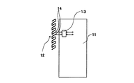
図1は、本発明の実施の形態1に係る無線通信端末用内蔵アンテナの構成を示す模式図である。なお、同図に示す各要素は、無線通信端末の筐体内に搭載されるものであるが、無線通信端末の全体図については、説明を簡単にするために省略する。
(Embodiment 1)
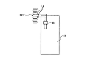
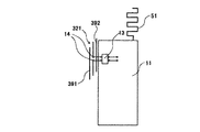
FIG. 1 is a schematic diagram showing a configuration of a built-in antenna for a wireless communication terminal according to Embodiment 1 of the present invention. Although each element shown in FIG. 1 is mounted in the housing of the wireless communication terminal, an overall view of the wireless communication terminal is omitted for simplicity of description.
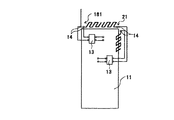
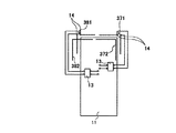
本実施の形態に係る無線通信端末用内蔵アンテナは、地板11と、ダイポールアンテナ12と、平衡不平衡変換回路13と、給電端14とを有して構成されている。以下、各構成要素について説明する。
The built-in antenna for a wireless communication terminal according to the present embodiment includes a
地板11は、板状の接地導体であり、無線通信端末における図示しない操作ボタン、ディスプレイ及びスピーカ等が設けられた面(鉛直面)と平行になるように取り付けられている。
The
ダイポールアンテナ12は、矩形波状(櫛刃状)に形成された2本のアンテナ素子によって構成されている。これにより、ダイポールアンテナは小型化されることになる。ダイポールアンテナ12を構成する2本のアンテナ素子は、それぞれの長手方向の中心線が同一直線上になるように配置されている。
The
また、ダイポールアンテナ12は、アンテナ素子の長手方向が無線通信端末の上面(水平面)と垂直になるように取り付けられている。結果として、ダイポールアンテナ12は、アンテナ素子の長手方向が水平面に対して垂直になるように設けられたことになる。これにより、ダイポールアンテナ12は、自由空間においては、主に、このダイポールアンテナ12の長手方向と平行な垂直偏波を受信する。さらに、通話時においては、人体が反射板として動作するので、ダイポールアンテナ12は、人体方向と逆の方向の指向性を有する。
The
平衡不平衡変換回路13は、1対1又はn対1(nは整数)のインピーダンス変換比を有する変換回路であり、ダイポールアンテナ12の給電端14に取り付けられている。つまり、平衡不平衡変換回路13の一方の端子は、図示しない送受信回路に接続され、また、もう一方の端子は、地板11に取り付けられている。これにより、平衡不平衡変換回路13は、ダイポールアンテナ12と上記送受信回路との間のインピーダンス変換を行うので、両者間のインピーダンス整合を適正にとることができる。さらに、平衡不平衡変換回路13は、上記送受信回路の不平衡信号を平衡信号に変換してダイポールアンテナ12に供給するので、地板11に流れる電流を極力抑えることができる。これにより、地板11のアンテナとしての作用が防止されるので、人体の影響に起因するダイポールアンテナ12の利得低下を抑えることができる。
The 不 balance-
次いで、上記構成の無線通信端末用内蔵アンテナの動作について説明する。上記送受信回路からの不平衡信号は、平衡不平衡変換回路13により平衡信号に変換された後、ダイポールアンテナ12に送られる。このように給電されたダイポールアンテナ12により、主に、このダイポールアンテナ12の長手方向と平行な垂直偏波が送信される。また、受信の際には、上記長手方向と平行な垂直偏波が受信される。したがって、自由空間においては、ダイポールアンテナ12を中心としてあらゆる方向からの垂直偏波が受信され、また、通話時においては、上述したように人体が反射板となるので、上記垂直偏波のうち、人体と反対の方向からの垂直偏波が主に受信される。
Next, the operation of the built-in antenna for a wireless communication terminal having the above configuration will be described. The unbalanced signal from the transmission / reception circuit is converted to a balanced signal by the balanced /
ダイポールアンテナ12により受信された上記信号(平衡信号)は、平衡不平衡変換回路13を介して、上記送受信回路に送られる。ここで、上述した平衡不平衡変換回路13により、地板11に流れる電流は極力抑えられるので、地板11によるアンテナ動作が防止される。これにより、人体の影響に起因する利得の低下が最小限に抑えられる。
The signal (balanced signal) received by the
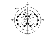
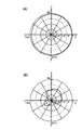
ここで、上記構成の無線通信端末用内蔵アンテナの受信特性について、図2を参照して説明する。図2は、本実施の形態に係る無線通信端末用内蔵アンテナの通話時における受信特性の実測値を示す図である。なお、ここでは、地板11の大きさを120×36mm、ダイポールアンテナ12の大きさを63×5mm、人体面からダイポールアンテナ12までの距離を5mm、周波数を2180MHzとした。また、図2において、原点から見て270度の方向が、図1におけるダイポールアンテナ12から見た人体の方向に相当する。
Here, the reception characteristics of the built-in antenna for a wireless communication terminal having the above configuration will be described with reference to FIG. FIG. 2 is a diagram showing measured values of reception characteristics of the built-in antenna for a wireless communication terminal according to the present embodiment during a call. Here, the size of the
図2から明らかなように、ダイポールアンテナ12は、人体が反射板として作用することによる影響を受けて、人体方向とは逆の方向に指向性を有するとともに、上述した理由により指向性の割れが防止されただけでなく、図95(B)に示した従来例と比べて、利得の劣化が抑えられた高い利得の特性を有している。
As is clear from FIG. 2, the
このように、本実施の形態によれば、平衡不平衡変換回路13において不平衡信号を平衡信号に変換することにより、地板11に流れるアンテナ電流を極力抑えることができるので、ダイポールアンテナ12の、人体の影響に起因する利得劣化を抑えることができる。さらに、ダイポールアンテナ12を矩形波状のアンテナ素子により構成したので、無線通信端末用内蔵アンテナを小型化することができる。したがって、人体の影響が少ない高利得で小型の無線通信端末用内蔵アンテナを提供することができる。
As described above, according to the present embodiment, by converting the unbalanced signal into the balanced signal in the balanced-
(実施の形態2)
実施の形態2は、実施の形態1においてダイポールアンテナ12の取り付け方法を変更した場合の形態である。実施の形態2は、ダイポールアンテナの取り付け方法以外については、実施の形態1と同様であるので、詳しい説明を省略する。以下、本実施の形態に係る無線通信端末用内蔵アンテナにおいて、実施の形態1と相違する点について、図3を用いて説明する。なお、実施の形態1と同様な部分については、同一符号を付して詳しい説明を省略する。
(Embodiment 2)
図3は、本発明の実施の形態2に係る無線通信端末用内蔵アンテナの構成を示す模式図である。この図に示すように、実施の形態2に係る無線通信端末用内蔵アンテナは、地板11と、ダイポールアンテナ12aと、平衡不平衡変換回路13と、給電端14とを有して構成されている。
FIG. 3 is a schematic diagram showing a configuration of a built-in antenna for a wireless communication terminal according to
ダイポールアンテナ12aは、アンテナ素子の長手方向が無線通信端末の上面(水平面)と平行になるように取り付けられている。すなわち、本実施の形態は、ダイポールアンテナ12aの長手方向が無線通信端末の上面(水平面)と平行であるという点で、実施の形態1と相違している。
The
これにより、ダイポールアンテナ12aは、利得の劣化を抑えることができるとともに、主に、このダイポールアンテナ12aの長手方向と平行な水平偏波を受信することができる。ところで、通信相手から送られる信号は、反射等の様々な要因により、垂直偏波と水平偏波が混在したものになる。したがって、水平偏波が多い場合には、アンテナの長手方向と信号の偏波面とが一致するので、受信利得を高くすることができる。
Thereby, the
このように、本実施の形態によれば、ダイポールアンテナ12aは、上記長手方向が無線通信端末の上面と平行になるように取り付けられているので、人体の影響に起因する利得劣化を抑えるだけでなく、主に水平偏波を受信することができる。したがって、アンテナの長手方向と通信相手からの信号の偏波面とが一致しないことに起因する利得劣化を防止することができ、人体の影響が少ない高利得で小型の無線通信端末用内蔵アンテナを提供することができる。
As described above, according to the present embodiment,
(実施の形態3)
実施の形態3は、実施の形態1においてダイポールアンテナ12の構成及び取り付け方法を変更した場合の形態である。実施の形態3は、ダイポールアンテナの構成及び取り付け方法以外については、実施の形態1と同様であるので、詳しい説明を省略する。以下、本実施の形態に係る無線通信端末用内蔵アンテナにおいて、実施の形態1と相違する点について、図4を用いて説明する。なお、実施の形態1と同様な部分については、同一符号を付して詳しい説明を省略する。
(Embodiment 3)
Embodiment 3 is an embodiment in which the configuration and mounting method of the
図4は、本発明の実施の形態3に係る無線通信端末用内蔵アンテナの構成を示す模式図である。この図に示すように、実施の形態3に係る無線通信端末用内蔵アンテナは、地板11と、ダイポールアンテナ21と、平衡不平衡変換回路13と、給電端14とを有して構成されている。ダイポールアンテナ21を構成する2本のアンテナ素子は、互いにそれぞれの長手方向が垂直になるように配置されている。
FIG. 4 is a schematic diagram showing a configuration of a built-in antenna for a wireless communication terminal according to Embodiment 3 of the present invention. As shown in this figure, the built-in antenna for a wireless communication terminal according to the third embodiment includes a
また、ダイポールアンテナ21は、一方のアンテナ素子の長手方向が無線通信端末の上面(水平面)と垂直になり、かつ、他方のアンテナ素子の長手方向が無線通信端末の上面(水平面)と平行になるように取り付けられている。
In the
次いで、上記構成の無線通信端末用内蔵アンテナの動作について説明する。上記送受信回路からの不平衡信号は、平衡不平衡変換回路13により平衡信号に変換された後、ダイポールアンテナ21に送られる。このように給電されたダイポールアンテナ21を構成する、無線通信端末の上面(水平面)と垂直に配置されたアンテナ素子により、主に、このアンテナ素子の長手方向と平行な垂直偏波が送信される。また、受信の際には、上記長手方向と平行な垂直偏波が受信される。一方、同様に給電されたダイポールアンテナ21を構成する、無線通信端末の上面(水平面)と平行に配置されたアンテナ素子により、主に、このアンテナ素子の長手方向と平行な水平偏波が送信される。また、受信の際には、上記長手方向と平行な水平偏波が受信される。したがって、自由空間においては、ダイポールアンテナ21を中心としてあらゆる方向からの垂直偏波及び水平偏波が受信され、また、通話時においては、上述したように人体が反射板となるので、上記垂直偏波及び水平偏波のうち、人体と反対の方向からの垂直偏波及び水平偏波が主に受信される。
Next, the operation of the built-in antenna for a wireless communication terminal having the above configuration will be described. The unbalanced signal from the transmitting / receiving circuit is converted to a balanced signal by the balanced /
これにより、ダイポールアンテナ21は、利得の劣化を抑えることができるとともに、各アンテナ素子の長手方向とそれぞれ平行な垂直偏波と水平偏波のいずれをも受信することができる。ところで、通信相手から送られる信号は、反射等の様々な要因により、垂直偏波と水平偏波が混在したものになる。したがって、垂直偏波と水平偏波のいずれが多い場合であっても、本実施の形態に係る無線通信端末用内蔵アンテナは、ダイポールアンテナ21の各アンテナ素子の長手方向のいずれかが通信相手から送られる信号の偏波面と一致するので、受信利得を高くすることができる。
Thereby, the
このように、本実施の形態によれば、平衡不平衡変換回路13により、地板11に流れるアンテナ電流を極力抑えることができるので、ダイポールアンテナ21の人体の影響に起因する利得劣化を抑えることができる。さらに、ダイポールアンテナ21を矩形波状のアンテナ素子により構成したので、無線通信端末用内蔵アンテナを小型化することができる。したがって、人体の影響が少ない高利得で小型の無線通信端末用内蔵アンテナを提供することができる。
As described above, according to the present embodiment, the antenna current flowing through the
(実施の形態4)
実施の形態4は、実施の形態1においてダイポールアンテナ12を構成するアンテナ素子の形状及びダイポールアンテナ12の取り付け方法を変更した場合の形態である。実施の形態4は、アンテナ素子の形状及びダイポールアンテナの取り付け方法以外については、実施の形態1と同様であるので、詳しい説明を省略する。以下、本実施の形態に係る無線通信端末用内蔵アンテナにおいて、実施の形態1と相違する点について、図5を用いて説明する。なお、実施の形態1と同様な部分については、同一符号を付して詳しい説明を省略する。
(Embodiment 4)
Embodiment 4 is an embodiment in which the shape of the antenna element forming the
図5は、本発明の実施の形態4に係る無線通信端末用内蔵アンテナの構成を示す模式図である。この図に示すように、実施の形態4に係る無線通信端末用内蔵アンテナは、地板11と、ダイポールアンテナ31と、平衡不平衡変換回路13と、給電端14とを有して構成されている。ダイポールアンテナ31を構成する2本のアンテナ素子は、それぞれ、中央付近で折り曲げられ、折り曲げられた面が互いに垂直になるように形成されている。ここで、この場合において、各アンテナ素子の互いに垂直な面のうち給電端14を有する方の面を第1の矩形波面といい、給電端14を有しない方の面を第2の矩形波面という。
FIG. 5 is a schematic diagram showing a configuration of a built-in antenna for a wireless communication terminal according to Embodiment 4 of the present invention. As shown in this figure, the built-in antenna for a wireless communication terminal according to the fourth embodiment includes a
上記構成のダイポールアンテナ31を構成する各アンテナ素子は、第1の矩形波面の長手方向が無線通信端末の上面(水平面)と平行になるように取り付けられている。また、上記各アンテナ素子は、第2の矩形波面の長手方向が無線通信端末の上面(水平面)と垂直になるように取り付けられている。
各 Each of the antenna elements constituting the
すなわち、本実施の形態は、ダイポールアンテナ31の各アンテナ素子について、第1の矩形波面の長手方向が無線通信端末の上面と平行であり、かつ、第2の矩形波面の長手方向が無線通信端末の上面と垂直であるという点で、実施の形態1と相違している。結果として、ダイポールアンテナ31は、実施の形態3と同様に、通話時において、一部分(上記第1の矩形波面)の長手方向が無線通信端末の上面(水平面)と平行になり、かつ、他の部分(上記第2の矩形波面)の長手方向が無線通信端末の上面(水平面)と垂直になるように設けられたことになる。
That is, in the present embodiment, for each antenna element of
このように、本実施の形態によれば、上記のような構成としても、実施の形態3と同様の効果を得ることができる。 As described above, according to the present embodiment, even with the above-described configuration, the same effect as that of the third embodiment can be obtained.
次の実施の形態5から実施の形態11は、実施の形態1から実施の形態4における無線通信端末用内蔵アンテナを用いてダイバーシチアンテナを実現する場合の形態である。
(実施の形態5)
実施の形態5は、実施の形態1における無線通信端末用内蔵アンテナを用いてダイバーシチアンテナを実現する場合の形態である。以下、本実施の形態に係る無線通信端末用ダイバーシチアンテナについて、図6を用いて説明する。なお、実施の形態1と同様な構成については、同一符号を付して詳しい説明を省略する。
(Embodiment 5)
図6は、本発明の実施の形態5に係る無線通信端末用ダイバーシチアンテナの構成を示す模式図である。図6において、実施の形態1に係る無線通信端末用内蔵アンテナの構成に加えて、モノポールアンテナ41がさらに設けられている。
FIG. 6 is a schematic diagram showing a configuration of a diversity antenna for a wireless communication terminal according to
ここで、ダイバーシチアンテナを構成する一方のアンテナを、実施の形態1におけるダイポールアンテナ12とし、かつ、受信専用とする。また、ダイバーシチアンテナを構成するもう一方のアンテナを、モノポールアンテナ41とし、かつ、送受信共用とする。
Here, one of the antennas constituting the diversity antenna is the
上記構成の無線通信端末用ダイバーシチアンテナにおいて、送信時には、モノポールアンテナ41のみが動作し、受信時には、ダイポールアンテナ12とモノポールアンテナ41の両方が動作して、ダイバーシチ受信が行われる。
In the diversity antenna for a wireless communication terminal having the above configuration, only the
このように、本実施の形態によれば、ダイバーシチアンテナとして、実施の形態1におけるダイポールアンテナ12が用いられるので、実施の形態1と同様に、人体の影響が少ない高利得で小型の無線通信端末用ダイバーシチアンテナを提供することができる。
As described above, according to the present embodiment,
(実施の形態6)
実施の形態6は、実施の形態5においてモノポールアンテナ41の構成を変更した場合の形態である。以下、本実施の形態に係る無線通信端末用ダイバーシチアンテナについて、図7を用いて説明する。なお、実施の形態5と同様な構成については、同一符号を付して詳しい説明を省略する。
(Embodiment 6)
Embodiment 6 is an embodiment in which the configuration of the
図7は、本発明の実施の形態6に係る無線通信端末用ダイバーシチアンテナの構成を示す模式図である。図7に示すように、本実施の形態に係る無線通信端末用ダイバーシチアンテナは、地板11と、ダイポールアンテナ12と、平衡不平衡変換回路13と、給電端14と、モノポールアンテナ51とを有して構成されている。モノポールアンテナ51は、矩形波状に形成されたアンテナ素子で構成されている。
FIG. 7 is a schematic diagram showing a configuration of a diversity antenna for wireless communication terminals according to Embodiment 6 of the present invention. As shown in FIG. 7, the diversity antenna for a wireless communication terminal according to the present embodiment includes a
上記構成の無線通信端末用ダイバーシチアンテナにおいて、送信時には、モノポールアンテナ51のみが動作し、受信時には、ダイポールアンテナ12とモノポールアンテナ51の両方が動作して、ダイバーシチ受信が行われる。
In the diversity antenna for a wireless communication terminal having the above configuration, only the
このように、本実施の形態によれば、ダイバーシチアンテナとして、実施の形態1におけるダイポールアンテナ12が用いられるので、人体の影響が少ない高利得な無線通信端末用ダイバーシチアンテナを提供することができる。さらに、モノポールアンテナ51を矩形波状としたので、外部アンテナを小型にすることができる。
As described above, according to the present embodiment, since
(実施の形態7)
実施の形態7は、実施の形態5においてモノポールアンテナ41の構成を変更した場合の形態である。以下、本実施の形態に係る無線通信端末用ダイバーシチアンテナについて、図8を用いて説明する。なお、実施の形態5と同様な構成については、同一符号を付して詳しい説明を省略する。
(Embodiment 7)
Embodiment 7 is an embodiment in which the configuration of the
図8は、本発明の実施の形態7に係る無線通信端末用ダイバーシチアンテナの構成を示す模式図である。この図に示すように、実施の形態7に係る無線通信端末用ダイバーシチアンテナは、地板11と、ダイポールアンテナ12と、平衡不平衡変換回路13と、給電端14と、モノポールアンテナ61とを有して構成されている。モノポールアンテナ61は、螺旋状に形成されたアンテナ素子で構成されている。
FIG. 8 is a schematic diagram showing a configuration of a diversity antenna for wireless communication terminals according to Embodiment 7 of the present invention. As shown in this figure, the diversity antenna for a wireless communication terminal according to the seventh embodiment includes a
上記構成の無線通信端末用ダイバーシチアンテナにおいて、送信時には、モノポールアンテナ61のみが動作し、受信時には、ダイポールアンテナ12とモノポールアンテナ61の両方が動作して、ダイバーシチ受信が行われる。
In the diversity antenna for a wireless communication terminal having the above configuration, only the
このように、本実施の形態によれば、上記のような構成としても、実施の形態6と同様の効果を得ることができる。 As described above, according to the present embodiment, even with the above-described configuration, the same effect as that of the sixth embodiment can be obtained.
(実施の形態8)
実施の形態8は、実施の形態1に係る無線通信端末用内蔵アンテナを用いてダイバーシチアンテナを実現する場合の形態である。以下、本実施の形態に係る無線通信端末用ダイバーシチアンテナについて、図9を用いて説明する。なお、実施の形態1と同様な構成については、同一符号を付して詳しい説明を省略する。
(Embodiment 8)
Embodiment 8 is an embodiment in which a diversity antenna is realized using the built-in antenna for a wireless communication terminal according to Embodiment 1. Hereinafter, the diversity antenna for wireless communication terminal according to the present embodiment will be described using FIG. In addition, about the structure similar to Embodiment 1, the same code | symbol is attached | subjected and detailed description is abbreviate | omitted.
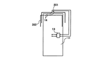
図9は、本発明の実施の形態8に係る無線通信端末用ダイバーシチアンテナの構成を示す模式図である。この図に示すように、実施の形態1に係る無線通信端末用内蔵アンテナの構成に加えて、別のダイポールアンテナ71がさらに地板11の側面に設けられている。なお、ダイポールアンテナ71は、ダイポールアンテナ12と同様の構成である。
FIG. 9 is a schematic diagram showing a configuration of a diversity antenna for a wireless communication terminal according to Embodiment 8 of the present invention. As shown in this figure, in addition to the configuration of the built-in antenna for a wireless communication terminal according to the first embodiment, another dipole antenna 71 is further provided on the side surface of
ここで、ダイバーシチアンテナを構成する一方のアンテナを、実施の形態1におけるダイポールアンテナ12とし、かつ、受信専用とする。また、ダイバーシチアンテナを構成するもう一方のアンテナを、ダイポールアンテナ71とし、かつ、送受信共用とする。
Here, one of the antennas constituting the diversity antenna is the
上記構成の無線通信端末用ダイバーシチアンテナにおいて、送信時には、ダイポールアンテナ71のみが動作し、受信時には、ダイポールアンテナ12とダイポールアンテナ71の両方が動作して、ダイバーシチ受信が行われる。
In the diversity antenna for a wireless communication terminal having the above configuration, only the dipole antenna 71 operates at the time of transmission, and at the time of reception, both the
このように、本実施の形態によれば、ダイバーシチアンテナとして、実施の形態1におけるダイポールアンテナ12及びこれと同様に構成されたダイポールアンテナ71が用いられるので、人体の影響が少ない高利得の無線通信端末用ダイバーシチアンテナを提供することができる。さらに、ダイポールアンテナ71をダイポールアンテナ12と同様に矩形波状のアンテナ素子により構成したので、ダイバーシチアンテナを小型にすることができる。
As described above, according to the present embodiment,
(実施の形態9)
実施の形態9は、実施の形態8においてダイポールアンテナ71の取り付け方法を変更した場合の形態である。実施の形態9は、ダイポールアンテナの取り付け方法以外については、実施の形態8と同様であるので、詳しい説明を省略する。以下、本実施の形態に係る無線通信端末用内蔵アンテナにおいて、実施の形態8と相違する点について、図10を用いて説明する。なお、実施の形態8と同様な部分については、同一符号を付して詳しい説明を省略する。
(Embodiment 9)
Embodiment 9 is an embodiment in which the mounting method of the dipole antenna 71 in Embodiment 8 is changed. The ninth embodiment is the same as the eighth embodiment except for the method of attaching the dipole antenna, and a detailed description thereof will be omitted. Hereinafter, differences between the built-in antenna for a wireless communication terminal according to the present embodiment and Embodiment 8 will be described with reference to FIG. The same parts as in the eighth embodiment are denoted by the same reference numerals, and detailed description is omitted.
図10は、本発明の実施の形態9に係る無線通信端末用内蔵アンテナの構成を示す模式図である。この図に示すように、追加のダイポールアンテナ71aは、その長手方向が無線通信端末の上面(水平面)と平行になるように取り付けられている。すなわち、本実施の形態は、ダイポールアンテナ71aの長手方向が無線通信端末の上面(水平面)と平行であるという点で、実施の形態8と相違している。結果として、ダイポールアンテナ71aは、その長手方向が、通話時において、人体に対して直角になると同時に水平面に対して平行になるように設けられたことになる。
FIG. 10 is a schematic diagram showing a configuration of a built-in antenna for a wireless communication terminal according to Embodiment 9 of the present invention. As shown in this figure, the
上記構成の無線通信端末用ダイバーシチアンテナにおいて、送信時には、ダイポールアンテナ71aのみが動作し、受信時には、ダイポールアンテナ12とダイポールアンテナ71aの両方が動作して、ダイバーシチ受信が行われる。
In the diversity antenna for a wireless communication terminal having the above configuration, only the
これにより、ダイポールアンテナ12は、利得の劣化を抑えることができるとともに、主に、アンテナ素子の長手方向と平行な垂直偏波を受信することができる。また、ダイポールアンテナ71aは、利得の劣化を抑えることができるとともに、主に、アンテナ素子の長手方向と平行な水平偏波を受信することができる。ところで、通信相手から送られる信号は、反射等の様々な要因により、垂直偏波と水平偏波が混在したものになる。したがって、垂直偏波と水平偏波のいずれが多い場合であっても、本実施の形態に係る無線通信端末用内蔵アンテナは、各ダイポールアンテナ12,71aの長手方向のいずれかが通信相手から送られる信号の偏波面と一致するので、受信利得を高くすることができる。
Thereby, the
このように、本実施の形態によれば、ダイバーシチアンテナとして、実施の形態1におけるダイポールアンテナ12及びこれと同様に構成されたダイポールアンテナ71aが用いられるので、人体の影響が少ない高利得の無線通信端末用ダイバーシチアンテナを提供することができる。さらに、ダイポールアンテナ71aをダイポールアンテナ12と同様に矩形波状のアンテナ素子により構成したので、ダイバーシチアンテナを小型にすることができる。
As described above, according to the present embodiment,
(実施の形態10)
実施の形態10は、図11に示すように、実施の形態8において送受信の双方に用いられるダイポールアンテナ71を実施の形態3のダイポールアンテナ21と同様に構成されたダイポールアンテナ81に変更した形態である。実施の形態10は、ダイポールアンテナ81の構成及び取り付け方法以外については、実施の形態8と同様である。なお、図11において、実施の形態8と同様な部分については、同一符号を付して詳しい説明を省略する。
(Embodiment 10)
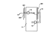
In the tenth embodiment, as shown in FIG. 11, a dipole antenna 71 used for both transmission and reception in the eighth embodiment is changed to a
図11は、本発明の実施の形態10に係る無線通信端末用ダイバーシチアンテナの構成を示す模式図である。この図に示すように、ダイポールアンテナ81は、一方のアンテナ素子の長手方向が無線通信端末の上面(水平面)と垂直になり、かつ、他方のアンテナ素子の長手方向が無線通信端末の上面(水平面)と平行になるように取り付けられている。
FIG. 11 is a schematic diagram showing a configuration of a diversity antenna for a wireless communication terminal according to
上記構成の無線通信端末用ダイバーシチアンテナにおいて、送信時には、ダイポールアンテナ81のみが動作し、受信時には、ダイポールアンテナ12とダイポールアンテナ81の両方が動作して、ダイバーシチ受信が行われる。
In the diversity antenna for a wireless communication terminal having the above configuration, only the
これにより、ダイポールアンテナ81は、利得の劣化を抑えることができるとともに、主に、各アンテナ素子の長手方向とそれぞれ平行な垂直偏波及び水平偏波を受信することができる。また、ダイポールアンテナ12は、利得の劣化を抑えることができるとともに、主に、アンテナ素子の長手方向と平行な垂直偏波を受信することができる。ところで、通信相手から送られる信号は、反射等の様々な要因により、垂直偏波と水平偏波が混在したものになる。したがって、垂直偏波と水平偏波のいずれが多い場合であっても、本実施の形態に係る無線通信端末用内蔵アンテナは、各ダイポールアンテナ12,81の各アンテナ素子の長手方向のいずれかが通信相手から送られる信号の偏波面と一致するので、受信利得を高くすることができる。
Thereby, the
このように、本実施の形態によれば、ダイバーシチアンテナとして、実施の形態1におけるダイポールアンテナ12及び実施の形態3におけるダイポールアンテナ21と同様に構成されたダイポールアンテナ81が用いられるので、人体の影響が少ない高利得の無線通信端末用ダイバーシチアンテナを提供することができる。さらに、ダイポールアンテナ81をダイポールアンテナ12と同様に矩形波状のアンテナ素子により構成したので、ダイバーシチアンテナを小型にすることができる。
As described above, according to the present embodiment,
(実施の形態11)
実施の形態11は、図12に示すように、実施の形態10において受信のみに用いられるダイポールアンテナ12を実施の形態3のダイポールアンテナ21と同様に構成されたダイポールアンテナ91に変更した形態である。実施の形態11は、ダイポールアンテナ91の構成及び取り付け方法以外については、実施の形態10と同様である。なお、図12において、実施の形態10と同様な部分については、同一符号を付して詳しい説明を省略する。
(Embodiment 11)
As shown in FIG. 12, the eleventh embodiment is a form in which the
図12は、本発明の実施の形態11に係る無線通信端末用ダイバーシチアンテナの構成を示す模式図である。この図に示すように、ダイポールアンテナ81及びダイポールアンテナ91は、いずれも、一方のアンテナ素子の長手方向が無線通信端末の上面(水平面)と垂直になり、かつ、他方のアンテナ素子の長手方向が無線通信端末の上面(水平面)と平行になるように取り付けられている。
FIG. 12 is a schematic diagram showing a configuration of a diversity antenna for a wireless communication terminal according to
上記構成の無線通信端末用ダイバーシチアンテナにおいて、送信時には、ダイポールアンテナ81のみが動作し、受信時には、ダイポールアンテナ81とダイポールアンテナ91の両方が動作して、ダイバーシチ受信が行われる。
In the diversity antenna for a wireless communication terminal having the above configuration, only the
これにより、ダイポールアンテナ81は、利得の劣化を抑えることができるとともに、主に、各アンテナ素子の長手方向とそれぞれ平行な垂直偏波及び水平偏波を受信することができる。また、ダイポールアンテナ91も、利得の劣化を抑えることができるとともに、主に、各アンテナ素子の長手方向とそれぞれ平行な垂直偏波及び水平偏波を受信することができる。ところで、通信相手から送られる信号は、反射等の様々な要因により、垂直偏波と水平偏波が混在したものになる。したがって、垂直偏波と水平偏波のいずれが多い場合であっても、本実施の形態に係る無線通信端末用内蔵アンテナは、各ダイポールアンテナ81,91の各アンテナ素子の長手方向のいずれかが通信相手から送られる信号の偏波面と一致するので、受信利得を高くすることができる。
Thereby, the
このように、本実施の形態によれば、ダイバーシチアンテナとして、実施の形態3におけるダイポールアンテナ21と同様に構成されたダイポールアンテナ81及びダイポールアンテナ91が用いられるので、人体の影響が少ない高利得な無線通信端末用ダイバーシチアンテナを提供することができる。さらに、各ダイポールアンテナ81,91を矩形波状としたことから、ダイバーシチアンテナを小型にすることができる。
As described above, according to the present embodiment,
(実施の形態12)
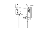
図13は、本発明の実施の形態12における折り返しダイポールアンテナ101の構成を示す模式図である。この図に示すように、実施の形態12における折り返しダイポールアンテナ101は、実施の形態1から実施の形態11で説明した矩形波状のダイポールアンテナのアンテナ素子を2組平行に配置し、この平行に配置した2組のアンテナ素子の先端を短絡して形成されている。
(Embodiment 12)
FIG. 13 is a schematic diagram showing a configuration of folded
上記構成の折り返しダイポールアンテナ101は、本明細書中の各実施の形態におけるダイポールアンテナとして適用可能である。
返 し The folded
このように、本実施の形態によれば、本明細書中の各実施の形態におけるダイポールアンテナとして折り返しダイポールアンテナ101を適用することにより、本明細書中の各実施の形態と同様の効果を得ることができ、さらに、インピーダンスをステップアップさせることができ、インピーダンス整合を容易に行うことができる。
As described above, according to the present embodiment, by applying the folded
(実施の形態13)
実施の形態13は、実施の形態12における折り返しダイポールアンテナ101の構成を変更したものである。実施の形態13は、ダイポールアンテナの構成以外については、実施の形態12と同様である。なお、図14において、実施の形態1から実施の形態11と同様な部分については、同一符号を付して詳しい説明を省略する。
(Embodiment 13)
In the thirteenth embodiment, the configuration of the folded
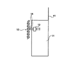
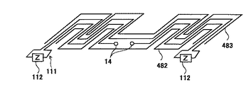
図14は、本発明の実施の形態13における折り返しダイポールアンテナ111の構成を示す模式図である。この図に示すように、実施の形態13における折り返しダイポールアンテナ111は、実施の形態1から実施の形態11で説明した矩形波状のダイポールアンテナのアンテナ素子を2組平行に配置し、この平行に配置した2組のアンテナ素子の先端にインピーダンス素子112をそれぞれ装荷して形成されている。
FIG. 14 is a schematic diagram showing a configuration of the folded
上記構成の折り返しダイポールアンテナ111は、本明細書中の各実施の形態におけるダイポールアンテナとして適用可能である。
The folded
このように、本実施の形態によれば、本明細書中の各実施の形態におけるダイポールアンテナとして折り返しダイポールアンテナ111を適用することにより、本明細書中の各実施の形態と同様の効果を得ることができ、さらに、インピーダンスをステップアップさせることができ、インピーダンス整合を容易に行うことができる。また、ダイポールアンテナを上記構成の折り返しダイポールアンテナ111とすることにより、広帯域化を図ることができ、アンテナをさらに小型化することができる。
As described above, according to the present embodiment, by applying the folded
(実施の形態14)
実施の形態14は、本明細書中の各実施の形態におけるダイポールアンテナの構成を変更したものである。実施の形態14は、ダイポールアンテナの構成及び取り付け方法以外については、実施の形態12と同様である。
(Embodiment 14)
図15は、本発明の実施の形態14におけるダイポールアンテナ121の構成を示す模式図である。この図に示すように、実施の形態14におけるダイポールアンテナ121は、螺旋状に形成された2本のアンテナ素子から構成されている。ダイポールアンテナ121を構成する2本のアンテナ素子は、それぞれの長手方向の中心線が同一直線上になるように配置されている。
FIG. 15 is a schematic diagram showing a configuration of
上記構成のダイポールアンテナ121は、本明細書中の各実施の形態におけるダイポールアンテナとして適用可能である。
The
このように、本実施の形態によれば、ダイポールアンテナを螺旋状のアンテナ素子から構成することにより、アンテナをさらに小型化することができる。 As described above, according to the present embodiment, the antenna can be further reduced in size by forming the dipole antenna from the spiral antenna element.
(実施の形態15)
実施の形態15は、本明細書中の各実施の形態におけるダイポールアンテナの構成を変更したものである。実施の形態15は、ダイポールアンテナの構成及び取り付け方法以外については、実施の形態12と同様である。
(Embodiment 15)
図16は、本発明の実施の形態15における折り返しダイポールアンテナ131の構成を示す模式図である。この図に示すように、実施の形態15における折り返しダイポールアンテナ131は、実施の形態14で説明した2組の螺旋状のダイポールアンテナ素子を平行に配置し、この2組のアンテナ素子の先端を短絡して形成されている。
FIG. 16 is a schematic diagram showing a configuration of the folded
上記構成の折り返しダイポールアンテナ131は、本明細書中の各実施の形態におけるダイポールアンテナとして適用可能である。
折 り The folded
このように、本実施の形態によれば、本明細書中の各実施の形態におけるダイポールアンテナとして折り返しダイポールアンテナ131を適用することにより、本明細書中の各実施の形態と同様の効果を得ることができ、さらに、インピーダンスをステップアップさせることができ、インピーダンス整合を容易に行うことができる。また、ダイポールアンテナを上記構成の折り返しダイポールアンテナ131とすることにより、アンテナをさらに小型化することができる。
As described above, according to the present embodiment, by applying the folded
(実施の形態16)
実施の形態16は、実施の形態15における折り返しダイポールアンテナ131の構成を変更したものである。実施の形態16は、ダイポールアンテナの構成及び取り付け方法以外については、実施の形態15と同様である。
(Embodiment 16)
In the sixteenth embodiment, the configuration of the folded
図17は、本発明の実施の形態16における折り返しダイポールアンテナ141の構成を示す模式図である。この図に示すように、実施の形態16における折り返しダイポールアンテナ141は、実施の形態14で説明した螺旋状のダイポールアンテナ121のアンテナ素子を2組平行に配置し、この平行に配置した2組のアンテナ素子の先端にインピーダンス素子142をそれぞれ装荷して形成されている。
FIG. 17 is a schematic diagram showing a configuration of the folded
上記構成の折り返しダイポールアンテナ141は、本明細書中の各実施の形態におけるダイポールアンテナとして適用可能である。
The folded
このように、本実施の形態によれば、ダイポールアンテナとして折り返しダイポールアンテナ141を適用することにより、実施の形態12と同様の効果を得ることができ、また、広帯域化及び小型化をも図ることができる。
As described above, according to the present embodiment, by applying the folded
なお、折り返しダイポールアンテナには自己平衡作用があるので、実施の形態12から実施の形態16(実施の形態14を除く)においては、平衡不平衡変換回路13を省略した構成としてもよい。
Since the folded dipole antenna has a self-balancing effect, a configuration in which the balance-
(実施の形態17)
実施の形態17は、実施の形態1におけるダイポールアンテナ12を、回路基板151上にパターン化して配置した形態である。
(Embodiment 17)
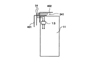
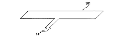
In the seventeenth embodiment, the
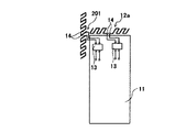
図18は、本発明の実施の形態17における回路基板151上に配置されたダイポールアンテナ12の構成を示す模式図である。この図に示すように、ダイポールアンテナ12は、回路基板151上にパターン化して配置されている。
FIG. 18 is a schematic diagram showing a configuration of
このように、本実施の形態によれば、実施の形態1におけるダイポールアンテナ12を用いているので、実施の形態1と同様の効果を得ることができる。また、実施の形態1におけるダイポールアンテナ12を回路基板151上にパターン化して配置したので、安定した特性を得ることができる。
As described above, according to the present embodiment, since the
なお、実施の形態1におけるダイポールアンテナ12以外に、本明細書中の他の各実施の形態におけるダイポールアンテナを回路基板151上にパターン化して配置するようにしてもよい。
In addition, other than the
(実施の形態18)
実施の形態18は、実施の形態1におけるダイポールアンテナ12を、筐体ケース161上にパターン化して配置した形態である。
(Embodiment 18)
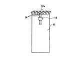
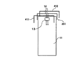
In the eighteenth embodiment, the
図19は、本発明の実施の形態18における筐体ケース161上に配置されたダイポールアンテナ12の構成を示す模式図である。この図に示すように、ダイポールアンテナ12は、筐体ケース161上にパターン化して配置されている。
FIG. 19 is a schematic diagram showing a configuration of
このように、本実施の形態によれば、実施の形態1におけるダイポールアンテナ12を用いているので、実施の形態1と同様の効果を得ることができる。また、実施の形態1におけるダイポールアンテナ12を筐体ケース161上にパターン化して配置したので、安定した特性を得ることができるとともに、アンテナの設置スペースを省略することができ、装置の小型化を図ることができる。
As described above, according to the present embodiment, since the
なお、実施の形態1におけるダイポールアンテナ12以外に、本明細書中の他の各実施の形態におけるダイポールアンテナを筐体ケース161上にパターン化して配置するようにしてもよい。
In addition, other than the
(実施の形態19)
実施の形態19は、実施の形態1においてダイポールアンテナ12の構成を変更した場合の形態である。実施の形態19は、ダイポールアンテナの構成以外については、実施の形態1と同様であるので、詳しい説明を省略する。以下、本実施の形態に係る無線通信端末用内蔵アンテナにおいて、実施の形態1と相違する点について、図20を用いて説明する。なお、実施の形態1と同様な部分については、同一符号を付して詳しい説明を省略する。
(Embodiment 19)
The nineteenth embodiment is an embodiment in which the configuration of the
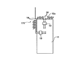
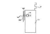
図20は、本発明の実施の形態19に係る無線通信端末用内蔵アンテナの構成を示す模式図である。この図に示すように、実施の形態19に係る無線通信端末用内蔵アンテナは、地板11と、平衡不平衡変換回路13と、給電端14と、ダイポールアンテナ171とを有して構成されている。ダイポールアンテナ171を構成する2本のアンテナ素子のうち、一方は矩形波状に形成され、他方は棒状に形成されている。この2本のアンテナ素子は、互いにそれぞれの長手方向の中心線が同一直線上になるように配置されている。また、棒状のアンテナ素子は、図示しない無線通信端末の外部に配置されている。
FIG. 20 is a schematic diagram showing a configuration of a built-in antenna for a wireless communication terminal according to Embodiment 19 of the present invention. As shown in this figure, the built-in antenna for a wireless communication terminal according to the nineteenth embodiment includes a
ダイポールアンテナ171は、矩形波状に形成されたアンテナ素子の長手方向が無線通信端末の上面(水平面)と垂直になるように、また、棒状に形成されたアンテナ素子の長手方向が無線通信端末の上面(水平面)と垂直になるように取り付けられている。
The
上述したように、ダイポールアンテナ171は、棒状に形成されたアンテナ素子の軸方向及び矩形波状に形成されたアンテナ素子の長手方向がそれぞれ無線通信端末の上面(水平面)と垂直になるように取り付けられている。これにより、ダイポールアンテナ171は、自由空間においては、主に、棒状のアンテナ素子の軸方向及び矩形波状のアンテナ素子の長手方向と平行な垂直偏波を受信する。さらに、通話時においては、人体が反射板として動作するので、ダイポールアンテナ171は、人体方向と逆の方向の指向性を有する。
As described above, the
次いで、上記構成の無線通信端末用内蔵アンテナの動作について説明する。上記送受信回路からの不平衡信号は、平衡不平衡変換回路13により平衡信号に変換された後、ダイポールアンテナ171に送られる。このように給電されたダイポールアンテナ171により、主に、このダイポールアンテナ171の長手方向と平行な垂直偏波が送信される。また、受信の際には、上記長手方向と平行な垂直偏波が受信される。したがって、自由空間においては、ダイポールアンテナ171を中心としてあらゆる方向からの垂直偏波が受信され、また、通話時においては、上述したように人体が反射板となるので、上記垂直偏波のうち、人体と反対の方向からの垂直偏波が主に受信される。
Next, the operation of the built-in antenna for a wireless communication terminal having the above configuration will be described. The unbalanced signal from the transmitting / receiving circuit is converted into a balanced signal by the balanced /
これにより、ダイポールアンテナ171は、利得の劣化を抑えることができるとともに、主に、このダイポールアンテナ171の長手方向と平行な垂直偏波を受信することができる。ところで、通信相手から送られる信号は、反射等の様々な要因により、垂直偏波と水平偏波が混在したものになる。したがって、垂直偏波が多い場合において、本実施の形態に係る無線通信端末用内蔵アンテナは、ダイポールアンテナ171の長手方向が通信相手から送られる信号の偏波面と一致するので、受信利得を高くすることができる。
Thereby, the
また、ダイポールアンテナ171により受信された上記信号(平衡信号)は、平衡不平衡変換回路13を介して、上記送受信回路に送られる。ここで、上述した平衡不平衡変換回路13により、地板11に流れる電流は極力抑えられるので、地板11によるアンテナ動作が防止される。これにより、人体の影響に起因する利得の低下が最小限に抑えられる。
{Circle around (2)} The signal (balanced signal) received by the
このように、本実施の形態によれば、平衡不平衡変換回路13により、地板11に流れるアンテナ電流を極力抑えることができるので、ダイポールアンテナ171の人体の影響に起因する利得劣化を抑えることができる。さらに、ダイポールアンテナ171の一方のアンテナ素子を矩形波状に形成したので、無線通信端末用内蔵アンテナを小型化することができる。したがって、人体の影響が少ない高利得で小型の無線通信端末用内蔵アンテナを提供することができる。
As described above, according to the present embodiment, the balance-
(実施の形態20)
実施の形態20は、実施の形態19においてダイポールアンテナ171の構成及び取り付け方法を変更した場合の形態である。実施の形態20は、ダイポールアンテナの構成及び取り付け方法以外については、実施の形態19と同様であるので、詳しい説明を省略する。以下、本実施の形態に係る無線通信端末用内蔵アンテナにおいて、実施の形態19と相違する点について、図21を用いて説明する。なお、実施の形態19と同様な部分については、同一符号を付して詳しい説明を省略する。
(Embodiment 20)
The twentieth embodiment is an embodiment in which the configuration and the mounting method of the
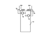
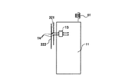
図21は、本発明の実施の形態20に係る無線通信端末用内蔵アンテナの構成を示す模式図である。この図に示すように、実施の形態20に係る無線通信端末用内蔵アンテナは、地板11と、平衡不平衡変換回路13と、給電端14と、ダイポールアンテナ181とを有して構成されている。ダイポールアンテナ181を構成する2本のアンテナ素子は、矩形波状に形成されたアンテナ素子の長手方向と、棒状に形成されたアンテナ素子の長手方向(軸方向)とが直交するように配置されている。
FIG. 21 is a schematic diagram showing a configuration of a built-in antenna for a wireless communication terminal according to
ダイポールアンテナ181は、矩形波状に形成されたアンテナ素子の長手方向が無線通信端末の上面(水平面)と平行になるように、また、棒状に形成されたアンテナ素子の軸方向が無線通信端末の上面(水平面)と垂直になるように取り付けられている。すなわち、本実施の形態は、ダイポールアンテナ181を構成する2本のアンテナ素子のうち矩形波状に形成されたアンテナ素子の長手方向が無線通信端末の上面(水平面)と平行であるという点で、実施の形態19と相違している。
The
次いで、上記構成の無線通信端末用内蔵アンテナの動作について説明する。上記送受信回路からの不平衡信号は、平衡不平衡変換回路13により平衡信号に変換された後、ダイポールアンテナ181に送られる。このように給電されたダイポールアンテナ181を構成する、無線通信端末の上面(水平面)と垂直に配置された棒状のアンテナ素子により、主に、この棒状のアンテナ素子の軸方向と平行な垂直偏波が送信される。また、受信の際には、上記軸方向と平行な垂直偏波が受信される。一方、同様に給電されたダイポールアンテナ181を構成する、無線通信端末の上面(水平面)と平行に配置された矩形波状のアンテナ素子により、主に、この矩形波状のアンテナ素子の長手方向と平行な水平偏波が送信される。また、受信の際には、上記長手方向と平行な水平偏波が受信される。したがって、自由空間においては、ダイポールアンテナ181を中心としてあらゆる方向からの垂直偏波及び水平偏波が受信され、また、通話時においては、上述したように人体が反射板となるので、上記垂直偏波及び水平偏波のうち、人体と反対の方向からの垂直偏波及び水平偏波が主に受信される。
Next, the operation of the built-in antenna for a wireless communication terminal having the above configuration will be described. The unbalanced signal from the transmitting / receiving circuit is converted to a balanced signal by the balanced /
これにより、ダイポールアンテナ181は、利得の劣化を抑えることができるとともに、各アンテナ素子の長手方向とそれぞれ平行な垂直偏波と水平偏波のいずれをも受信することができる。ところで、通信相手から送られる信号は、反射等の様々な要因により、垂直偏波と水平偏波が混在したものになる。したがって、垂直偏波と水平偏波のいずれが多い場合であっても、本実施の形態に係る無線通信端末用内蔵アンテナは、ダイポールアンテナ181の各アンテナ素子の長手方向のいずれかが通信相手から送られる信号の偏波面と一致するので、受信利得を高くすることができる。
Thereby, the
このように、本実施の形態によっても、実施の形態19と同様の効果を得ることができる。 As described above, according to the present embodiment, the same effect as in the nineteenth embodiment can be obtained.
(実施の形態21)
実施の形態21は、実施の形態19においてダイポールアンテナ171の構成及び取り付け方法を変更した場合の形態である。実施の形態21は、ダイポールアンテナの構成及び取り付け方法以外については、実施の形態19と同様であるので、詳しい説明を省略する。以下、本実施の形態に係る無線通信端末用内蔵アンテナにおいて、実施の形態19と相違する点について、図22を用いて説明する。なお、実施の形態19と同様な部分については、同一符号を付して詳しい説明を省略する。
(Embodiment 21)
図22は、本発明の実施の形態21に係る無線通信端末用内蔵アンテナの構成を示す模式図である。この図に示すように、実施の形態21に係る無線通信端末用内蔵アンテナは、地板11と、平衡不平衡変換回路13と、給電端14と、ダイポールアンテナ191とを有して構成されている。ダイポールアンテナ191を構成する2本のアンテナ素子は、それぞれ、中央付近で折り曲げられ、折り曲げられた各アンテナ素子について給電端14を有する側は矩形波状に形成され、給電端14を有しない側は棒状に形成されており、互いに各アンテナ素子の矩形波状に形成された部分の長手方向の中心線が同一直線上になるように配置されている。また、各アンテナ素子の棒状の部分は、図示しない無線通信端末の筐体の外部に配置されている。
FIG. 22 is a schematic diagram showing a configuration of a built-in antenna for a wireless communication terminal according to
上記構成のダイポールアンテナ191を構成する各アンテナ素子の矩形波状に形成された部分は、その長手方向が無線通信端末の上面(水平面)と平行になるように取り付けられている。この場合、各アンテナ素子の棒状の部分は、無線通信装置の上面(水平面)と垂直になるように位置されている。
{Circle around (1)} A rectangular wave-shaped portion of each antenna element constituting the
ダイポールアンテナ191は、各アンテナ素子の矩形波状に形成された部分の長手方向が無線通信端末の上面(水平面)と平行になるように取り付けられている。このように取り付けることによって、各アンテナ素子の棒状に形成された部分は、その軸方向が無線通信端末の上面(水平面)と垂直になる。
The
次いで、上記構成の無線通信端末用内蔵アンテナの動作について説明する。上記送受信回路からの不平衡信号は、平衡不平衡変換回路13により平衡信号に変換された後、ダイポールアンテナ191に送られる。このように給電されたダイポールアンテナ191を構成する、無線通信端末の上面(水平面)と垂直に配置されたアンテナ素子の棒状の部分により、主に、この棒状部分の軸方向と平行な垂直偏波が送信される。また、受信の際には、上記軸方向と平行な垂直偏波が受信される。一方、同様に給電されたダイポールアンテナ191を構成する、無線通信端末の上面(水平面)と平行に配置されたアンテナ素子の矩形波状の部分により、主に、この矩形波状部分の長手方向と平行な水平偏波が送信される。また、受信の際には、上記長手方向と平行な水平偏波が受信される。したがって、自由空間においては、ダイポールアンテナ191を中心としてあらゆる方向からの垂直偏波及び水平偏波が受信され、また、通話時においては、上述したように人体が反射板となるので、上記垂直偏波及び水平偏波のうち、人体と反対の方向からの垂直偏波及び水平偏波が主に受信される。
Next, the operation of the built-in antenna for a wireless communication terminal having the above configuration will be described. The unbalanced signal from the transmitting / receiving circuit is converted to a balanced signal by the balanced /
これにより、ダイポールアンテナ191は、利得の劣化を抑えることができるとともに、主に、各アンテナ素子の矩形波状の部分の長手方向と平行な水平偏波及び各アンテナ素子の棒状の部分の軸方向と平行な垂直偏波を受信することができる。ところで、通信相手から送られる信号は、反射等の様々な要因により、垂直偏波と水平偏波が混在したものになる。したがって、垂直偏波と水平偏波のいずれが多い場合であっても、本実施の形態に係る無線通信端末用内蔵アンテナは、ダイポールアンテナ191の各アンテナ素子の各部分の長手方向のいずれかが通信相手から送られる信号の偏波面と一致するので、受信利得を高くすることができる。
Thus, the
このように、本実施の形態によっても、実施の形態20と同様の効果を得ることができる。 As described above, according to the present embodiment, the same effect as in the twentieth embodiment can be obtained.
(実施の形態22)
実施の形態22は、実施の形態19においてダイポールアンテナ171を構成する棒状に形成されたアンテナ素子の構成を変更した場合の形態である。以下、本実施の形態に係る無線通信端末用アンテナについて、図23を用いて説明する。なお、実施の形態19と同様な構成については、同一符号を付して詳しい説明を省略する。
(Embodiment 22)
Embodiment 22 is an embodiment in which the configuration of the rod-shaped antenna element forming the
図23は、本発明の実施の形態22に係る無線通信端末用ダイバーシチアンテナの構成を示す模式図である。図23に示すように、実施の形態22に係る無線通信端末用アンテナは、地板11と、平衡不平衡変換回路13と、ダイポールアンテナ201とを有して構成されている。ダイポールアンテナ201は、実施の形態19におけるダイポールアンテナ171を構成する2本のアンテナ素子のうち、棒状に形成されたアンテナ素子を矩形波状に形成した構成を採る。
FIG. 23 is a schematic diagram showing a configuration of a diversity antenna for a wireless communication terminal according to Embodiment 22 of the present invention. As shown in FIG. 23, the antenna for a wireless communication terminal according to the twenty-second embodiment includes a
次いで、上記構成の無線通信端末用内蔵アンテナの動作について説明する。上記送受信回路からの不平衡信号は、平衡不平衡変換回路13により平衡信号に変換された後、ダイポールアンテナ201に送られる。このように給電されたダイポールアンテナ201は、このダイポールアンテナ201の長手方向が無線通信端末の上面(水平面)と垂直になるように配置されているので、主に、このダイポールアンテナ201の長手方向と平行な垂直偏波を送信する。また、受信の際には、上記長手方向と平行な垂直偏波を受信する。したがって、自由空間においては、ダイポールアンテナ201を中心としてあらゆる方向からの垂直偏波が受信され、また、通話時においては、上述したように人体が反射板となるので、上記垂直偏波のうち、人体と反対の方向からの垂直偏波が主に受信される。
Next, the operation of the built-in antenna for a wireless communication terminal having the above configuration will be described. The unbalanced signal from the transmitting / receiving circuit is converted to a balanced signal by the balanced /
これにより、ダイポールアンテナ201は、利得の劣化を抑えることができるとともに、主に、このダイポールアンテナ201の長手方向と平行な垂直偏波を受信することができる。ところで、通信相手から送られる信号は、反射等の様々な要因により、垂直偏波と水平偏波が混在したものになる。したがって、垂直偏波が多い場合において、本実施の形態に係る無線通信端末用内蔵アンテナは、ダイポールアンテナ201の長手方向が通信相手から送られる信号の偏波面と一致するので、受信利得を高くすることができる。
Thereby, the
このように、本実施の形態によれば、実施の形態19と同様の効果を得ることができるとともに、外部アンテナをより小型にすることができる。 As described above, according to the present embodiment, the same effects as those of the nineteenth embodiment can be obtained, and the size of the external antenna can be reduced.
(実施の形態23)
実施の形態23は、実施の形態20においてダイポールアンテナ181を構成する2本のアンテナ素子のうち棒状に形成されたアンテナ素子の構成を変更した場合の形態である。以下、本実施の形態に係る無線通信端末用アンテナについて、図24を用いて説明する。なお、実施の形態20と同様な構成については、同一符号を付して詳しい説明を省略する。
Embodiment 23
Embodiment 23 is an embodiment in which the configuration of the rod-shaped antenna element of the two antenna elements forming the
図24は、本発明の実施の形態23に係る無線通信端末用アンテナの構成を示す模式図である。図24に示すように、実施の形態23に係る無線通信端末用アンテナは、地板11と、平衡不平衡変換回路13と、ダイポールアンテナ211とを有して構成されている。ダイポールアンテナ211は、実施の形態20におけるダイポールアンテナ181を構成する2本のアンテナ素子のうち、棒状に形成されたアンテナ素子を矩形波状に変更した構成を採る。
FIG. 24 is a schematic diagram showing a configuration of a wireless communication terminal antenna according to Embodiment 23 of the present invention. As shown in FIG. 24, the antenna for a wireless communication terminal according to the twenty-third embodiment includes a
次いで、上記構成の無線通信端末用内蔵アンテナの動作について説明する。上記送受信回路からの不平衡信号は、平衡不平衡変換回路13により平衡信号に変換された後、ダイポールアンテナ211に送られる。このように給電されたダイポールアンテナ211は、一方のアンテナ素子の長手方向が無線通信端末の上面(水平面)と垂直に配置され、他方のアンテナ素子の長手方向が無線通信端末の上面(水平面)と平行に配置されているので、このダイポールアンテナ211の各アンテナ素子の長手方向とそれぞれ平行な垂直偏波及び水平偏波を送信する。また、受信の際には、上記長手方向とそれぞれ平行な垂直偏波及び水平偏波を受信する。したがって、自由空間においては、ダイポールアンテナ211を中心としてあらゆる方向からの垂直偏波及び水平偏波が受信され、また、通話時においては、上述したように人体が反射板となるので、上記垂直偏波及び水平偏波のうち、人体と反対の方向からの垂直偏波及び水平偏波が主に受信される。
Next, the operation of the built-in antenna for a wireless communication terminal having the above configuration will be described. The unbalanced signal from the transmitting / receiving circuit is converted to a balanced signal by the balanced /
これにより、ダイポールアンテナ211は、利得の劣化を抑えることができるとともに、主に、このダイポールアンテナ211の各アンテナ素子の長手方向とそれぞれ平行な垂直偏波及び水平偏波を受信することができる。ところで、通信相手から送られる信号は、反射等の様々な要因により、垂直偏波と水平偏波が混在したものになる。したがって、垂直偏波と水平偏波のいずれが多い場合であっても、本実施の形態に係る無線通信端末用内蔵アンテナは、ダイポールアンテナ211の各アンテナ素子の長手方向のいずれかが通信相手から送られる信号の偏波面と一致するので、受信利得を高くすることができる。
Accordingly, the
このように、本実施の形態によれば、実施の形態20と同様の効果を得ることができるとともに、外部アンテナをより小型にすることができる。 As described above, according to the present embodiment, the same effects as those of the twentieth embodiment can be obtained, and the external antenna can be made smaller.
(実施の形態24)
実施の形態24は、実施の形態21においてダイポールアンテナ191を構成する各アンテナ素子の棒状の部分の構成を変更した場合の形態である。以下、本実施の形態に係る無線通信端末用アンテナについて、図25を用いて説明する。なお、実施の形態21と同様な構成については、同一符号を付して詳しい説明を省略する。
(Embodiment 24)
Embodiment 24 is an embodiment in which the configuration of the rod-shaped portion of each antenna element forming the
図25は、本発明の実施の形態24に係る無線通信端末用内蔵アンテナの構成を示す模式図である。図25に示すように、本実施の形態24に係る無線通信端末用アンテナは、地板11と、平衡不平衡変換回路13と、給電端14と、ダイポールアンテナ221とを有して構成されている。ダイポールアンテナ221は、実施の形態21におけるダイポールアンテナ191を構成する各アンテナ素子の棒状に形成された部分を矩形波状に変更した構成を採る。
FIG. 25 is a schematic diagram showing a configuration of a built-in antenna for a wireless communication terminal according to Embodiment 24 of the present invention. As shown in FIG. 25, the antenna for a wireless communication terminal according to the twenty-fourth embodiment includes a
次いで、上記構成の無線通信端末用内蔵アンテナの動作について説明する。上記送受信回路からの不平衡信号は、平衡不平衡変換回路13により平衡信号に変換された後、ダイポールアンテナ221に送られる。このように給電されたダイポールアンテナ221を構成する各アンテナ素子の、無線通信端末の上面(水平面)と垂直に配置された部分により、主に、この部分の長手方向と平行な垂直偏波が送信される。また、受信の際には、上記長手方向と平行な垂直偏波が受信される。一方、同様に給電されたダイポールアンテナ221を構成する各アンテナ素子の、無線通信端末の上面(水平面)と平行に配置された部分により、主に、この部分の長手方向と平行な水平偏波が送信される。また、受信の際には、上記長手方向と平行な水平偏波が受信される。したがって、自由空間においては、ダイポールアンテナ221を中心としてあらゆる方向からの垂直偏波及び水平偏波が受信され、また、通話時においては、上述したように人体が反射板となるので、上記垂直偏波及び水平偏波のうち、人体と反対の方向からの垂直偏波及び水平偏波が主に受信される。
Next, the operation of the built-in antenna for a wireless communication terminal having the above configuration will be described. The unbalanced signal from the transmitting / receiving circuit is converted to a balanced signal by the balanced /
これにより、ダイポールアンテナ221は、利得の劣化を抑えることができるとともに、主に、各アンテナ素子の各部分の長手方向とそれぞれ平行な垂直偏波及び水平偏波を受信することができる。ところで、通信相手から送られる信号は、反射等の様々な要因により、垂直偏波と水平偏波が混在したものになる。したがって、垂直偏波と水平偏波のいずれが多い場合であっても、本実施の形態に係る無線通信端末用内蔵アンテナは、ダイポールアンテナ221の各アンテナ素子の各部分の長手方向のいずれかが通信相手から送られる信号の偏波面と一致するので、受信利得を高くすることができる。
Thereby, the
このように、本実施の形態によれば、実施の形態21と同様の効果を得ることができるとともに、外部アンテナをより小型にすることができる。 As described above, according to the present embodiment, the same effects as those of the twenty-first embodiment can be obtained, and the size of the external antenna can be reduced.
次の実施の形態25から実施の形態38は、実施の形態19から実施の形態24における無線通信端末用内蔵アンテナを用いてダイバーシチアンテナを実現する場合の形態である。 Next, the twenty-fifth embodiment to the thirty-eighth embodiment are modes in which a diversity antenna is realized using the built-in antenna for a wireless communication terminal in the nineteenth to twenty-fourth embodiments.
(実施の形態25)
実施の形態25は、実施の形態19に係る無線通信端末用内蔵アンテナを用いてダイバーシチアンテナを実現する場合の形態である。以下、本実施の形態に係る無線通信端末用ダイバーシチアンテナについて、図26を用いて説明する。なお、実施の形態19と同様な構成については、同一符号を付して詳しい説明を省略する。
(Embodiment 25)
Embodiment 25 is an embodiment in which a diversity antenna is realized by using the built-in antenna for a wireless communication terminal according to Embodiment 19. Hereinafter, the diversity antenna for wireless communication terminal according to the present embodiment will be described using FIG. Note that the same components as those of the nineteenth embodiment are denoted by the same reference numerals, and detailed description is omitted.
図26は、本発明の実施の形態25に係る無線通信端末用ダイバーシチアンテナの構成を示す模式図である。図26において、実施の形態19に係る無線通信端末用内蔵アンテナの構成に加えて、ダイポールアンテナ231がさらに設けられている。ダイポールアンテナ231は、実施の形態19におけるダイポールアンテナ171と同様の構成である。
FIG. 26 is a schematic diagram showing a configuration of a diversity antenna for a wireless communication terminal according to Embodiment 25 of the present invention. In FIG. 26, a
ここで、ダイバーシチアンテナを構成する一方のアンテナを、実施の形態19におけるダイポールアンテナ171とし、かつ、受信専用とする。また、ダイバーシチアンテナを構成するもう一方のアンテナを、ダイポールアンテナ231とし、かつ、送受信共用とする。
Here, one of the antennas constituting the diversity antenna is the
上記構成の無線通信端末用ダイバーシチアンテナにおいて、送信時には、ダイポールアンテナ231のみが動作し、受信時には、ダイポールアンテナ171とダイポールアンテナ231の両方が動作して、ダイバーシチ受信が行われる。
In the diversity antenna for a wireless communication terminal having the above configuration, only the
このように、本実施の形態によれば、ダイバーシチアンテナとして、実施の形態19におけるダイポールアンテナ171及びこれと同様に構成されたダイポールアンテナ231が用いられるので、実施の形態19と同様に、人体の影響が少ない高利得で小型の無線通信端末用ダイバーシチアンテナを提供することができる。
As described above, according to the present embodiment,
(実施の形態26)
実施の形態26は、実施の形態20に係る無線通信端末用内蔵アンテナを用いてダイバーシチアンテナを実現する場合の形態である。以下、本実施の形態に係る無線通信端末用ダイバーシチアンテナについて、図27を用いて説明する。なお、実施の形態20と同様な構成については、同一符号を付して詳しい説明を省略する。
(Embodiment 26)
Embodiment 26 is an embodiment in which a diversity antenna is realized using the built-in antenna for a wireless communication terminal according to
図27は、本発明の実施の形態26に係る無線通信端末用ダイバーシチアンテナの構成を示す模式図である。図27において、実施の形態20における無線通信端末用内蔵アンテナの構成に加えて、ダイポールアンテナ241がさらに設けられている。ダイポールアンテナ241は、実施の形態20におけるダイポールアンテナ181と同様の構成である。
FIG. 27 is a schematic diagram showing a configuration of a diversity antenna for wireless communication terminals according to Embodiment 26 of the present invention. In FIG. 27, a
ここで、ダイバーシチアンテナを構成する一方のアンテナを、実施の形態20におけるダイポールアンテナ181とし、かつ、受信専用とする。また、ダイバーシチアンテナを構成するもう一方のアンテナを、ダイポールアンテナ241とし、かつ、送受信共用とする。
Here, one of the antennas constituting the diversity antenna is the
上記構成の無線通信端末用ダイバーシチアンテナにおいて、送信時には、ダイポールアンテナ241のみが動作し、受信時には、ダイポールアンテナ181とダイポールアンテナ241の両方が動作して、ダイバーシチ受信が行われる。
In the diversity antenna for a wireless communication terminal having the above configuration, only the
このように、本実施の形態によれば、ダイバーシチアンテナとして、実施の形態20におけるダイポールアンテナ181及びこれと同様に構成されたダイポールアンテナ241が用いられるので、実施の形態20と同様に、人体の影響が少ない高利得で小型の無線通信端末用ダイバーシチアンテナを提供することができる。
As described above, according to the present embodiment,
(実施の形態27)
実施の形態27は、実施の形態22に係る無線通信端末用内蔵アンテナを用いてダイバーシチアンテナを実現する場合の形態である。以下、本実施の形態に係る無線通信端末用ダイバーシチアンテナについて、図28を用いて説明する。なお、実施の形態22と同様な構成については、同一符号を付して詳しい説明を省略する。
(Embodiment 27)
Embodiment 27 is an embodiment in which a diversity antenna is realized using the built-in antenna for a wireless communication terminal according to Embodiment 22. Hereinafter, the diversity antenna for wireless communication terminal according to the present embodiment will be described using FIG. In addition, about the structure similar to Embodiment 22, the same code | symbol is attached | subjected and detailed description is abbreviate | omitted.
図28は、本発明の実施の形態27に係る無線通信端末用ダイバーシチアンテナの構成を示す模式図である。図28において、実施の形態22に係る無線通信端末用内蔵アンテナの構成に加えて、ダイポールアンテナ251がさらに設けられている。ダイポールアンテナ251は、実施の形態22におけるダイポールアンテナ201と同様の構成である。
FIG. 28 is a schematic diagram showing a configuration of a diversity antenna for a wireless communication terminal according to Embodiment 27 of the present invention. In FIG. 28, a
ここで、ダイバーシチアンテナを構成する一方のアンテナを、実施の形態22におけるダイポールアンテナ201とし、かつ、受信専用とする。また、ダイバーシチアンテナを構成するもう一方のアンテナを、ダイポールアンテナ251とし、かつ、送受信共用とする。
Here, one of the antennas constituting the diversity antenna is the
上記構成の無線通信端末用ダイバーシチアンテナにおいて、送信時には、ダイポールアンテナ251のみが動作し、受信時には、ダイポールアンテナ201とダイポールアンテナ251の両方が動作して、ダイバーシチ受信が行われる。
In the diversity antenna for a wireless communication terminal having the above configuration, only the
このように、本実施の形態によれば、ダイバーシチアンテナとして、実施の形態22におけるダイポールアンテナ201及びこれと同様に構成されたダイポールアンテナ251が用いられるので、実施の形態22と同様に、人体の影響が少ない高利得で小型の無線通信端末用ダイバーシチアンテナを提供することができる。
As described above, according to the present embodiment,
(実施の形態28)
実施の形態28は、実施の形態23に係る無線通信端末用内蔵アンテナを用いてダイバーシチアンテナを実現する場合の形態である。以下、本実施の形態に係る無線通信端末用ダイバーシチアンテナについて、図29を用いて説明する。なお、実施の形態23と同様な構成については、同一符号を付して詳しい説明を省略する。
(Embodiment 28)
Embodiment 28 is an embodiment in which a diversity antenna is realized using the built-in antenna for a wireless communication terminal according to Embodiment 23. Hereinafter, the diversity antenna for wireless communication terminal according to the present embodiment will be described using FIG. In addition, about the structure similar to Embodiment 23, the same code | symbol is attached | subjected and detailed description is abbreviate | omitted.
図29は、本発明の実施の形態28に係る無線通信端末用ダイバーシチアンテナの構成を示す模式図である。図29において、実施の形態23に係る無線通信端末用内蔵アンテナの構成に加えて、ダイポールアンテナ261がさらに設けられている。ダイポールアンテナ261は、実施の形態23におけるダイポールアンテナ211と同様の構成である。
FIG. 29 is a schematic diagram showing a configuration of a diversity antenna for a wireless communication terminal according to Embodiment 28 of the present invention. In FIG. 29, a
ここで、ダイバーシチアンテナを構成する一方のアンテナを、実施の形態23におけるダイポールアンテナ211とし、かつ、受信専用とする。また、ダイバーシチアンテナを構成するもう一方のアンテナを、ダイポールアンテナ261とし、かつ、送受信共用とする。
Here, one of the antennas constituting the diversity antenna is the
上記構成の無線通信端末用ダイバーシチアンテナにおいて、送信時には、ダイポールアンテナ261のみが動作し、受信時には、ダイポールアンテナ211とダイポールアンテナ261の両方が動作して、ダイバーシチ受信が行われる。
In the diversity antenna for a wireless communication terminal having the above configuration, only the
このように、本実施の形態によれば、ダイバーシチアンテナとして、実施の形態23におけるダイポールアンテナ211及びこれと同様に構成されたダイポールアンテナ261が用いられるので、実施の形態23と同様に、人体の影響が少ない高利得で小型の無線通信端末用ダイバーシチアンテナを提供することができる。
As described above, according to the present embodiment,
(実施の形態29)
実施の形態29は、実施の形態1及び実施の形態19に係る無線通信端末用内蔵アンテナを用いてダイバーシチアンテナを実現する場合の形態である。以下、本実施の形態に係る無線通信端末用ダイバーシチアンテナについて、図30を用いて説明する。なお、実施の形態1及び実施の形態19と同様な構成については、同一符号を付して詳しい説明を省略する。
(Embodiment 29)
Embodiment 29 is an embodiment in which a diversity antenna is realized using the built-in antenna for a radio communication terminal according to Embodiments 1 and 19. Hereinafter, the diversity antenna for wireless communication terminal according to the present embodiment will be described using FIG. In addition, about the structure similar to Embodiment 1 and Embodiment 19, the same code | symbol is attached | subjected and detailed description is abbreviate | omitted.
図30は、本発明の実施の形態29に係る無線通信端末用ダイバーシチアンテナの構成を示す模式図である。図30において、実施の形態19に係る無線通信端末用内蔵アンテナの構成に加えて、実施の形態1におけるダイポールアンテナ12がさらに設けられている。
FIG. 30 is a schematic diagram showing a configuration of a diversity antenna for a wireless communication terminal according to Embodiment 29 of the present invention. 30, a
ここで、ダイバーシチアンテナを構成する一方のアンテナを、実施の形態1におけるダイポールアンテナ12とし、かつ、受信専用とする。また、ダイバーシチアンテナを構成するもう一方のアンテナを、実施の形態19におけるダイポールアンテナ171とし、かつ、送受信共用とする。
Here, one of the antennas constituting the diversity antenna is the
上記構成の無線通信端末用ダイバーシチアンテナにおいて、送信時には、ダイポールアンテナ171のみが動作し、受信時には、ダイポールアンテナ171とダイポールアンテナ12の両方が動作して、ダイバーシチ受信が行われる。
In the diversity antenna for a wireless communication terminal having the above configuration, only the
このように、本実施の形態によれば、ダイバーシチアンテナとして、実施の形態1におけるダイポールアンテナ12及び実施の形態19におけるダイポールアンテナ171が用いられるので、実施の形態19と同様に、人体の影響が少ない高利得で小型の無線通信端末用ダイバーシチアンテナを提供することができる。
As described above, according to the present embodiment,
(実施の形態30)
実施の形態30は、実施の形態2及び実施の形態19に係る無線通信端末用内蔵アンテナを用いてダイバーシチアンテナを実現する場合の形態である。以下、本実施の形態に係る無線通信端末用ダイバーシチアンテナについて、図31を用いて説明する。なお、実施の形態2及び実施の形態19と同様な構成については、同一符号を付して詳しい説明を省略する。
(Embodiment 30)
Embodiment 30 is an embodiment in which a diversity antenna is realized using the built-in antenna for a wireless communication terminal according to
図31は、本発明の実施の形態30に係る無線通信端末用ダイバーシチアンテナの構成を示す模式図である。図31において、実施の形態19に係る無線通信端末用内蔵アンテナの構成に加えて、実施の形態2におけるダイポールアンテナ12aがさらに設けられている。
FIG. 31 is a schematic diagram showing a configuration of a diversity antenna for a wireless communication terminal according to Embodiment 30 of the present invention. In FIG. 31, a
ここで、ダイバーシチアンテナを構成する一方のアンテナを、実施の形態2におけるダイポールアンテナ12aとし、かつ、受信専用とする。また、ダイバーシチアンテナを構成するもう一方のアンテナを、実施の形態19におけるダイポールアンテナ171とし、かつ、送受信共用とする。
Here, one of the antennas constituting the diversity antenna is the
上記構成の無線通信端末用ダイバーシチアンテナにおいて、送信時には、ダイポールアンテナ171のみが動作し、受信時には、ダイポールアンテナ171とダイポールアンテナ12aの両方が動作して、ダイバーシチ受信が行われる。
In the diversity antenna for a wireless communication terminal having the above configuration, only the
このように、本実施の形態によれば、ダイバーシチアンテナとして、実施の形態2におけるダイポールアンテナ12a及び実施の形態19におけるダイポールアンテナ171が用いられるので、実施の形態2及び実施の形態19と同様に、人体の影響が少ない高利得で小型の無線通信端末用ダイバーシチアンテナを提供することができる。
As described above, according to the present embodiment,
(実施の形態31)
実施の形態31は、実施の形態3及び実施の形態19に係る無線通信端末用内蔵アンテナを用いてダイバーシチアンテナを実現する場合の形態である。以下、本実施の形態に係る無線通信端末用ダイバーシチアンテナについて、図32を用いて説明する。なお、実施の形態3及び実施の形態19と同様な構成については、同一符号を付して詳しい説明を省略する。
(Embodiment 31)
図32は、本発明の実施の形態31に係る無線通信端末用ダイバーシチアンテナの構成を示す模式図である。図32において、実施の形態19に係る無線通信端末用内蔵アンテナの構成に加えて、実施の形態3におけるダイポールアンテナ21がさらに設けられている。
FIG. 32 is a schematic diagram showing a configuration of a diversity antenna for a wireless communication terminal according to
ここで、ダイバーシチアンテナを構成する一方のアンテナを、実施の形態3におけるダイポールアンテナ21とし、かつ、受信専用とする。また、ダイバーシチアンテナを構成するもう一方のアンテナを、実施の形態19におけるダイポールアンテナ171とし、かつ、送受信共用とする。
Here, one of the antennas constituting the diversity antenna is the
上記構成の無線通信端末用ダイバーシチアンテナにおいて、送信時には、ダイポールアンテナ171のみが動作し、受信時には、ダイポールアンテナ171とダイポールアンテナ21の両方が動作して、ダイバーシチ受信が行われる。
In the diversity antenna for a wireless communication terminal having the above configuration, only the
このように、本実施の形態によれば、ダイバーシチアンテナとして、実施の形態3におけるダイポールアンテナ21及び実施の形態19におけるダイポールアンテナ171が用いられるので、実施の形態3及び実施の形態19と同様に、人体の影響が少ない高利得で小型の無線通信端末用ダイバーシチアンテナを提供することができる。
As described above, according to the present embodiment,
(実施の形態32)
実施の形態32は、実施の形態1及び実施の形態20に係る無線通信端末用内蔵アンテナを用いてダイバーシチアンテナを実現する場合の形態である。以下、本実施の形態に係る無線通信端末用ダイバーシチアンテナについて、図33を用いて説明する。なお、実施の形態1及び実施の形態20と同様な構成については、同一符号を付して詳しい説明を省略する。
(Embodiment 32)
Embodiment 32 is an embodiment in which a diversity antenna is realized using the built-in antenna for a wireless communication terminal according to
図33は、本発明の実施の形態32に係る無線通信端末用ダイバーシチアンテナの構成を示す模式図である。図33において、実施の形態20に係る無線通信端末用内蔵アンテナの構成に加えて、実施の形態1におけるダイポールアンテナ12がさらに設けられている。
FIG. 33 is a schematic diagram showing a configuration of a diversity antenna for a wireless communication terminal according to Embodiment 32 of the present invention. 33, a
ここで、ダイバーシチアンテナを構成する一方のアンテナを、実施の形態1におけるダイポールアンテナ12とし、かつ、受信専用とする。また、ダイバーシチアンテナを構成するもう一方のアンテナを、実施の形態20におけるダイポールアンテナ181とし、かつ、送受信共用とする。
Here, one of the antennas constituting the diversity antenna is the
上記構成の無線通信端末用ダイバーシチアンテナにおいて、送信時には、ダイポールアンテナ181のみが動作し、受信時には、ダイポールアンテナ181とダイポールアンテナ12の両方が動作して、ダイバーシチ受信が行われる。
In the diversity antenna for a wireless communication terminal having the above configuration, only the
このように、本実施の形態によれば、ダイバーシチアンテナとして、実施の形態1におけるダイポールアンテナ12及び実施の形態20におけるダイポールアンテナ181が用いられるので、実施の形態1及び実施の形態20と同様に、人体の影響が少ない高利得で小型の無線通信端末用ダイバーシチアンテナを提供することができる。
As described above, according to the present embodiment,
(実施の形態33)
実施の形態33は、実施の形態3及び実施の形態20に係る無線通信端末用内蔵アンテナを用いてダイバーシチアンテナを実現する場合の形態である。以下、本実施の形態に係る無線通信端末用ダイバーシチアンテナについて、図34を用いて説明する。なお、実施の形態3及び実施の形態20と同様な構成については、同一符号を付して詳しい説明を省略する。
(Embodiment 33)
Embodiment 33 is an embodiment in which a diversity antenna is realized by using the built-in antenna for a radio communication terminal according to
図34は、本発明の実施の形態33に係る無線通信端末用ダイバーシチアンテナの構成を示す模式図である。図34において、実施の形態20に係る無線通信端末用内蔵アンテナの構成に加えて、実施の形態3におけるダイポールアンテナ21がさらに設けられている。
FIG. 34 is a schematic diagram showing a configuration of a diversity antenna for a wireless communication terminal according to Embodiment 33 of the present invention. In FIG. 34, a
ここで、ダイバーシチアンテナを構成する一方のアンテナを、実施の形態3におけるダイポールアンテナ21とし、かつ、受信専用とする。また、ダイバーシチアンテナを構成するもう一方のアンテナを、実施の形態20におけるダイポールアンテナ181とし、かつ、送受信共用とする。
Here, one of the antennas constituting the diversity antenna is the
上記構成の無線通信端末用ダイバーシチアンテナにおいて、送信時には、ダイポールアンテナ181のみが動作し、受信時には、ダイポールアンテナ181とダイポールアンテナ21の両方が動作して、ダイバーシチ受信が行われる。
In the diversity antenna for a wireless communication terminal having the above configuration, only the
このように、本実施の形態によれば、ダイバーシチアンテナとして、実施の形態3におけるダイポールアンテナ21及び実施の形態20におけるダイポールアンテナ181が用いられるので、実施の形態3及び実施の形態20と同様に、人体の影響が少ない高利得で小型の無線通信端末用ダイバーシチアンテナを提供することができる。
As described above, according to the present embodiment,
(実施の形態34)
実施の形態34は、実施の形態1及び実施の形態22に係る無線通信端末用内蔵アンテナを用いてダイバーシチアンテナを実現する場合の形態である。以下、本実施の形態に係る無線通信端末用ダイバーシチアンテナについて、図35を用いて説明する。なお、実施の形態1及び実施の形態22と同様な構成については、同一符号を付して詳しい説明を省略する。
(Embodiment 34)
Embodiment 34 is an embodiment in which a diversity antenna is realized by using the built-in antenna for a wireless communication terminal according to Embodiments 1 and 22. Hereinafter, the diversity antenna for wireless communication terminal according to the present embodiment will be described using FIG. In addition, about the structure similar to Embodiment 1 and Embodiment 22, the same code | symbol is attached | subjected and detailed description is abbreviate | omitted.
図35は、本発明の実施の形態34に係る無線通信端末用ダイバーシチアンテナの構成を示す模式図である。図35において、実施の形態22に係る無線通信端末用内蔵アンテナの構成に加えて、実施の形態1におけるダイポールアンテナ12がさらに設けられている。
FIG. 35 is a schematic diagram showing a configuration of a diversity antenna for a wireless communication terminal according to Embodiment 34 of the present invention. In FIG. 35, in addition to the configuration of the built-in antenna for a wireless communication terminal according to the twenty-second embodiment,
ここで、ダイバーシチアンテナを構成する一方のアンテナを、実施の形態1におけるダイポールアンテナ12とし、かつ、受信専用とする。また、ダイバーシチアンテナを構成するもう一方のアンテナを、実施の形態22におけるダイポールアンテナ201とし、かつ、送受信共用とする。
Here, one of the antennas constituting the diversity antenna is the
上記構成の無線通信端末用ダイバーシチアンテナにおいて、送信時には、ダイポールアンテナ201のみが動作し、受信時には、ダイポールアンテナ201とダイポールアンテナ12の両方が動作して、ダイバーシチ受信が行われる。
In the diversity antenna for a wireless communication terminal having the above configuration, only the
このように、本実施の形態によれば、ダイバーシチアンテナとして、実施の形態1におけるダイポールアンテナ12及び実施の形態22におけるダイポールアンテナ201が用いられるので、実施の形態1及び実施の形態22と同様に、人体の影響が少ない高利得で小型の無線通信端末用ダイバーシチアンテナを提供することができる。
As described above, according to the present embodiment,
(実施の形態35)
実施の形態35は、実施の形態2及び実施の形態22に係る無線通信端末用内蔵アンテナを用いてダイバーシチアンテナを実現する場合の形態である。以下、本実施の形態に係る無線通信端末用ダイバーシチアンテナについて、図36を用いて説明する。なお、実施の形態2及び実施の形態22と同様な構成については、同一符号を付して詳しい説明を省略する。
(Embodiment 35)
Embodiment 35 is an embodiment in which a diversity antenna is realized using the built-in antenna for a wireless communication terminal according to
図36は、本発明の実施の形態35に係る無線通信端末用ダイバーシチアンテナの構成を示す模式図である。図36において、実施の形態22に係る無線通信端末用内蔵アンテナの構成に加えて、実施の形態2におけるダイポールアンテナ12aがさらに設けられている。
FIG. 36 is a schematic diagram showing a configuration of a diversity antenna for wireless communication terminals according to Embodiment 35 of the present invention. In FIG. 36, in addition to the configuration of the built-in antenna for a wireless communication terminal according to the twenty-second embodiment, a
ここで、ダイバーシチアンテナを構成する一方のアンテナを、実施の形態2におけるダイポールアンテナ12aとし、かつ、受信専用とする。また、ダイバーシチアンテナを構成するもう一方のアンテナを、実施の形態22におけるダイポールアンテナ201とし、かつ、送受信共用とする。
Here, one of the antennas constituting the diversity antenna is the
上記構成の無線通信端末用ダイバーシチアンテナにおいて、送信時には、ダイポールアンテナ201のみが動作し、受信時には、ダイポールアンテナ201とダイポールアンテナ12aの両方が動作して、ダイバーシチ受信が行われる。
In the diversity antenna for a wireless communication terminal having the above configuration, only the
このように、本実施の形態によれば、ダイバーシチアンテナとして、実施の形態2におけるダイポールアンテナ12a及び実施の形態22におけるダイポールアンテナ201が用いられるので、実施の形態2及び実施の形態22と同様に、人体の影響が少ない高利得で小型の無線通信端末用ダイバーシチアンテナを提供することができる。
As described above, according to the present embodiment,
(実施の形態36)
実施の形態36は、実施の形態3及び実施の形態22に係る無線通信端末用内蔵アンテナを用いて、ダイバーシチアンテナを実現する場合の形態である。以下、本実施の形態に係る無線通信端末用ダイバーシチアンテナについて、図37を用いて説明する。なお、実施の形態3及び実施の形態22と同様な構成については、同一符号を付して詳しい説明を省略する。
(Embodiment 36)
Embodiment 36 is an embodiment in which a diversity antenna is realized by using the built-in antenna for a wireless communication terminal according to Embodiments 3 and 22. Hereinafter, the diversity antenna for wireless communication terminal according to the present embodiment will be described using FIG. In addition, about the structure similar to Embodiment 3 and Embodiment 22, the same code | symbol is attached | subjected and detailed description is abbreviate | omitted.
図37は、本発明の実施の形態36に係る無線通信端末用ダイバーシチアンテナの構成を示す模式図である。図37において、実施の形態22に係る無線通信端末用内蔵アンテナの構成に加えて、実施の形態3におけるダイポールアンテナ21がさらに設けられている。
FIG. 37 is a schematic diagram showing a configuration of a diversity antenna for a wireless communication terminal according to Embodiment 36 of the present invention. In FIG. 37, in addition to the configuration of the built-in antenna for a wireless communication terminal according to the twenty-second embodiment, a
ここで、ダイバーシチアンテナを構成する一方のアンテナを、実施の形態3におけるダイポールアンテナ21とし、かつ、受信専用とする。また、ダイバーシチアンテナを構成するもう一方のアンテナを、実施の形態22におけるダイポールアンテナ201とし、かつ、送受信共用とする。
Here, one of the antennas constituting the diversity antenna is the
上記構成の無線通信端末用ダイバーシチアンテナにおいて、送信時には、ダイポールアンテナ201のみが動作し、受信時には、ダイポールアンテナ201とダイポールアンテナ21の両方が動作して、ダイバーシチ受信が行われる。
In the diversity antenna for a wireless communication terminal having the above configuration, only the
このように、本実施の形態によれば、ダイバーシチアンテナとして、実施の形態3におけるダイポールアンテナ21及び実施の形態22におけるダイポールアンテナ201が用いられるので、実施の形態3及び実施の形態22と同様に、人体の影響が少ない高利得で小型の無線通信端末用ダイバーシチアンテナを提供することができる。
As described above, according to the present embodiment,
(実施の形態37)
実施の形態37は、実施の形態1及び実施の形態23に係る無線通信端末用内蔵アンテナを用いてダイバーシチアンテナを実現する場合の形態である。以下、本実施の形態に係る無線通信端末用ダイバーシチアンテナについて、図38を用いて説明する。なお、実施の形態1及び実施の形態23と同様な構成については、同一符号を付して詳しい説明を省略する。
(Embodiment 37)
Embodiment 37 is an embodiment in which a diversity antenna is realized by using the built-in antenna for a wireless communication terminal according to Embodiments 1 and 23. Hereinafter, the diversity antenna for wireless communication terminal according to the present embodiment will be described using FIG. In addition, about the structure similar to Embodiment 1 and Embodiment 23, the same code | symbol is attached | subjected and detailed description is abbreviate | omitted.
図38は、本発明の実施の形態37に係る無線通信端末用ダイバーシチアンテナの構成を示す模式図である。図38において、実施の形態23に係る無線通信端末用内蔵アンテナの構成に加えて、実施の形態1におけるダイポールアンテナ12がさらに設けられている。
FIG. 38 is a schematic diagram showing a configuration of a diversity antenna for a radio communication terminal according to Embodiment 37 of the present invention. In FIG. 38, a
ここで、ダイバーシチアンテナを構成する一方のアンテナを、実施の形態1におけるダイポールアンテナ12とし、かつ、受信専用とする。また、ダイバーシチアンテナを構成するもう一方のアンテナを、実施の形態23におけるダイポールアンテナ211とし、かつ、送受信共用とする。
Here, one of the antennas constituting the diversity antenna is the
上記構成の無線通信端末用ダイバーシチアンテナにおいて、送信時には、ダイポールアンテナ211のみが動作し、受信時には、ダイポールアンテナ211とダイポールアンテナ12の両方が動作して、ダイバーシチ受信が行われる。
In the diversity antenna for a wireless communication terminal having the above configuration, only the
このように、本実施の形態によれば、ダイバーシチアンテナとして、実施の形態1におけるダイポールアンテナ12及び実施の形態23におけるダイポールアンテナ211が用いられるので、実施の形態1及び実施の形態23と同様に、人体の影響が少ない高利得で小型の無線通信端末用ダイバーシチアンテナを提供することができる。
As described above, according to the present embodiment,
(実施の形態38)
実施の形態38は、実施の形態3及び実施の形態23に係る無線通信端末用内蔵アンテナを用いて、ダイバーシチアンテナを実現する場合の形態である。以下、本実施の形態に係る無線通信端末用ダイバーシチアンテナについて、図39を用いて説明する。なお、実施の形態3及び実施の形態23と同様な構成については、同一符号を付して詳しい説明を省略する。
(Embodiment 38)
Embodiment 38 is an embodiment in which a diversity antenna is realized by using the built-in antenna for a wireless communication terminal according to Embodiments 3 and 23. Hereinafter, the diversity antenna for wireless communication terminal according to the present embodiment will be described using FIG. In addition, about the structure similar to Embodiment 3 and Embodiment 23, the same code | symbol is attached | subjected and detailed description is abbreviate | omitted.
図39は、本発明の実施の形態38に係る無線通信端末用ダイバーシチアンテナの構成を示す模式図である。図39において、実施の形態23に係る無線通信端末用内蔵アンテナの構成に加えて、実施の形態3におけるダイポールアンテナ21がさらに設けられている。
FIG. 39 is a schematic diagram showing a configuration of a diversity antenna for a wireless communication terminal according to Embodiment 38 of the present invention. In FIG. 39, in addition to the configuration of the built-in antenna for a wireless communication terminal according to the twenty-third embodiment, a
ここで、ダイバーシチアンテナを構成する一方のアンテナを、実施の形態3におけるダイポールアンテナ21とし、かつ、受信専用とする。また、ダイバーシチアンテナを構成するもう一方のアンテナを、実施の形態23におけるダイポールアンテナ211とし、かつ、送受信共用とする。
Here, one of the antennas constituting the diversity antenna is the
上記構成の無線通信端末用ダイバーシチアンテナにおいて、送信時には、ダイポールアンテナ211のみが動作し、受信時には、ダイポールアンテナ211とダイポールアンテナ21の両方が動作して、ダイバーシチ受信が行われる。
In the diversity antenna for a wireless communication terminal having the above configuration, only the
このように、本実施の形態によれば、ダイバーシチアンテナとして、実施の形態3におけるダイポールアンテナ21及び実施の形態23におけるダイポールアンテナ211が用いられるので、実施の形態3及び実施の形態23と同様に、人体の影響が少ない高利得で小型の無線通信端末用ダイバーシチアンテナを提供することができる。
As described above, according to the present embodiment,
(実施の形態39)
実施の形態39は、実施の形態3においてダイポールアンテナ21の構成を変更した場合の形態である。実施の形態39は、ダイポールアンテナの構成以外については、実施の形態3と同様であるので、詳しい説明を省略する。以下、本実施の形態に係る無線通信端末用内蔵アンテナにおいて、実施の形態3と相違する点について、図40を用いて説明する。なお、実施の形態3と同様な部分については、同一符号を付して詳しい説明を省略する。
(Embodiment 39)
Embodiment 39 is an embodiment in which the configuration of the
図40は、本発明の実施の形態39に係る無線通信端末用内蔵アンテナの構成を示す模式図である。この図に示すように、実施の形態39に係る無線通信端末用内蔵アンテナは、地板11と、平行不平行変換回路13と、ダイポールアンテナ221とを有して構成されている。ダイポールアンテナ221を構成する2本のアンテナ素子のうち、一方は矩形波状に形成され、他方は棒状に形成されている。この2本のアンテナ素子は、矩形波状のアンテナ素子の長手方向と棒状のアンテナ素子の軸方向とが直交するように配置されている。
FIG. 40 is a schematic diagram showing a configuration of a built-in antenna for a wireless communication terminal according to Embodiment 39 of the present invention. As shown in this figure, the built-in antenna for a wireless communication terminal according to the thirty-ninth embodiment includes a
ダイポールアンテナ221は、矩形波状に形成されたアンテナ素子の長手方向が無線通信端末の上面(水平面)と垂直になるように、また、棒状に形成されたアンテナ素子の軸方向が無線通信端末の上面(水平面)と平行になるように取り付けられている。
The
上述したように、ダイポールアンテナ221は、矩形波状に形成されたアンテナ素子の長手方向が無線通信端末の上面(水平面)と垂直になるように、また、棒状に形成されたアンテナ素子の軸方向が無線通信端末の上面(水平面)と平行になるように取り付けられている。これにより、ダイポールアンテナ221は、自由空間においては、矩形波状に形成されたアンテナ素子の長手方向と平行な垂直偏波及び棒状に形成されたアンテナ素子の軸方向と平行な水平偏波を受信する。さらに、通話時においては、人体が反射板として動作するので、ダイポールアンテナ221は、人体方向と逆の方向の指向性を有する。
As described above, the
次いで、上記構成の無線通信端末用内蔵アンテナの動作について説明する。上記送受信回路からの不平衡信号は、平衡不平衡変換回路13により平衡信号に変換された後、ダイポールアンテナ221に送られる。このように給電されたダイポールアンテナ221の矩形波状に形成されたアンテナ素子により、主に、この矩形波状に形成されたアンテナ素子の長手方向と平行な垂直偏波が送信される。また、受信の際には、上記長手方向と平行な垂直偏波が受信される。一方、このように給電されたダイポールアンテナ221の棒状に形成されたアンテナ素子により、主に、この棒状に形成されたアンテナ素子の軸方向と平行な水平偏波が送信される。また、受信の際には、上記軸方向と平行な水平偏波が受信される。したがって、自由空間においては、ダイポールアンテナ221を中心としてあらゆる方向からの垂直偏波及び水平偏波が受信され、また、通話時においては、上述したように人体が反射板となるので、上記垂直偏波及び水平偏波のうち、人体と反対の方向からの垂直偏波及び水平偏波が主に受信される。
Next, the operation of the built-in antenna for a wireless communication terminal having the above configuration will be described. The unbalanced signal from the transmitting / receiving circuit is converted to a balanced signal by the balanced /
また、ダイポールアンテナ221により受信された上記信号(平衡信号)は、平衡不平衡変換回路13を介して、上記送受信回路に送られる。ここで、上述した平衡不平衡変換回路13により、地板11に流れる電流は極力抑えられるので、地板11によるアンテナ動作が防止される。これにより、人体の影響に起因する利得の低下が最小限に抑えられる。
(4) The signal (balanced signal) received by the
このように、本実施の形態によれば、平衡不平衡変換回路13により、地板11に流れるアンテナ電流を極力抑えることができるので、ダイポールアンテナ221の人体の影響に起因する利得劣化を抑えることができる。さらに、ダイポールアンテナ221の一方のアンテナ素子を矩形波状に形成したので、無線通信端末用内蔵アンテナを小型化することができる。したがって、人体の影響が少ない高利得で小型の無線通信端末用内蔵アンテナを提供することができる。
As described above, according to the present embodiment, the balance-
さらに、垂直偏波を主に矩形波状のアンテナ素子で受信し、水平偏波を主に棒状のアンテナ素子で受信するため、垂直偏波と水平偏波の偏波比を適宜変化させることができるので、アンテナの使用目的に応じた偏波比で受信することができる。 Furthermore, since the vertically polarized wave is mainly received by the rectangular wave-shaped antenna element and the horizontally polarized wave is mainly received by the rod-shaped antenna element, the polarization ratio between the vertically polarized wave and the horizontally polarized wave can be appropriately changed. Therefore, reception can be performed with a polarization ratio according to the purpose of use of the antenna.
(実施の形態40)
実施の形態40は、実施の形態39においてダイポールアンテナ221の構成を変更した場合の形態である。実施の形態40は、ダイポールアンテナの構成以外については、実施の形態39と同様であるので、詳しい説明を省略する。以下、本実施の形態に係る無線通信端末用内蔵アンテナにおいて、実施の形態39と相違する点について、図41を用いて説明する。なお、実施の形態39と同様な部分については、同一符号を付して詳しい説明を省略する。
(Embodiment 40)
Embodiment 40 is an embodiment in which the configuration of the
図41は、本発明の実施の形態40に係る無線通信端末用内蔵アンテナの構成を示す模式図である。この図に示すように、実施の形態40に係る無線通信端末用内蔵アンテナは、地板11と、平衡不平衡変換回路13と、ダイポールアンテナ231とを有して構成されている。ダイポールアンテナ231を構成する2本のアンテナ素子は、矩形波状のアンテナ素子の長手方向と棒状のアンテナ素子の軸方向とが直交するように配置されている。
FIG. 41 is a schematic diagram showing a configuration of a built-in antenna for a wireless communication terminal according to Embodiment 40 of the present invention. As shown in this figure, the built-in antenna for a wireless communication terminal according to the fortieth embodiment includes a
ダイポールアンテナ231は、矩形波状に形成されたアンテナ素子の長手方向が無線通信端末の上面(水平面)と平行になるように、また、棒状に形成されたアンテナ素子の軸方向が無線通信端末の上面(水平面)と垂直になるように取り付けられている。すなわち、本実施の形態は、矩形波状のアンテナ素子の長手方向が無線通信端末の上面(水平面)と平行であり、かつ、棒状のアンテナ素子の軸方向が無線通信端末の上面(水平面)と垂直であるという点で、実施の形態39と相違している。
The
これにより、ダイポールアンテナ231は、自由空間においては、矩形波状に形成されたアンテナ素子の長手方向と平行な水平偏波及び棒状に形成されたアンテナ素子の軸方向と平行な垂直偏波を受信する。さらに、通話時においては、人体が反射板として動作するので、ダイポールアンテナ231は、人体方向と逆の方向の指向性を有する。
Thus, in free space, the
このように、本実施の形態によっても、実施の形態39と同様の効果を得ることができる。さらに、垂直偏波を主に棒状のアンテナ素子で受信し、水平偏波を主に矩形波状のアンテナ素子で受信するため、垂直偏波と水平偏波の偏波比を適宜変化させることができるので、アンテナの使用目的に応じた偏波比で受信することができる。 As described above, according to the present embodiment, the same effect as in the thirty-ninth embodiment can be obtained. Furthermore, since the vertically polarized wave is mainly received by the rod-shaped antenna element and the horizontally polarized wave is mainly received by the rectangular wave-shaped antenna element, the polarization ratio between the vertically polarized wave and the horizontally polarized wave can be appropriately changed. Therefore, reception can be performed with a polarization ratio according to the purpose of use of the antenna.
(実施の形態41)
実施の形態41は、実施の形態4においてダイポールアンテナ31の構成を変更した場合の形態である。実施の形態41は、ダイポールアンテナの構成以外については、実施の形態4と同様であるので、詳しい説明を省略する。以下、本実施の形態に係る無線通信端末用内蔵アンテナにおいて、実施の形態4と相違する点について、図42を用いて説明する。なお、実施の形態4と同様な部分については、同一符号を付して詳しい説明を省略する。
(Embodiment 41)
図42は、本発明の実施の形態41に係る無線通信端末用内蔵アンテナの構成を示す模式図である。この図に示すように、実施の形態41に係る無線通信端末用内蔵アンテナは、地板11と、平行不平行変換回路13と、給電端14と、ダイポールアンテナ241とを有して構成されている。ダイポールアンテナ241を構成する2本のアンテナ素子は、それぞれ、中央付近で折り曲げられ、折り曲げられた各アンテナ素子について給電端14を有する側は棒状に形成され、給電端14を有しない側は矩形波状に形成されている。そして、2つのアンテナ素子は、それぞれの棒状の部分が同一直線上になるように配置されている。
FIG. 42 is a schematic diagram showing a configuration of a built-in antenna for a wireless communication terminal according to
ダイポールアンテナ241は、各アンテナ素子の矩形波状に形成された部分の長手方向が無線通信端末の上面(水平面)と垂直になるように、また、各アンテナ素子の棒状に形成された部分の軸方向が無線通信端末の上面(水平面)と平行になるように取り付けられている。
The
これにより、ダイポールアンテナ241は、自由空間においては、各アンテナ素子の矩形波状に形成された部分の長手方向と平行な垂直偏波及び各アンテナ素子の棒状に形成された部分の軸方向と平行な水平偏波を受信する。さらに、通話時においては、人体が反射板として動作するので、ダイポールアンテナ241は、人体方向と逆の方向の指向性を有する。
Thus, in free space, the
次いで、上記構成の無線通信端末用内蔵アンテナの動作について説明する。上記送受信回路からの不平衡信号は、平衡不平衡変換回路13により平衡信号に変換された後、ダイポールアンテナ241に送られる。このように給電されたダイポールアンテナ241を構成する各アンテナ素子の矩形波状に形成された部分により、主に、この矩形波状に形成された部分の長手方向と平行な垂直偏波が送信される。また、受信の際には、上記長手方向と平行な垂直偏波が受信される。一方、このように給電されたダイポールアンテナ241を構成する各アンテナ素子の棒状に形成された部分により、主に、この棒状に形成された部分の軸方向と平行な平行偏波が送信される。また、受信の際には、上記軸方向と平行な水平偏波が受信される。自由空間においては、ダイポールアンテナ241を中心としてあらゆる方向からの垂直偏波及び水平偏波が受信され、また、通話時においては、上述したように人体が反射板となるので、上記垂直偏波及び水平偏波のうち、人体と反対の方向からの垂直偏波及び水平偏波が主に受信される。
Next, the operation of the built-in antenna for a wireless communication terminal having the above configuration will be described. The unbalanced signal from the transmitting / receiving circuit is converted into a balanced signal by the balanced /
また、ダイポールアンテナ241により受信された上記信号(平衡信号)は、平衡不平衡変換回路13を介して、上記送受信回路に送られる。ここで、上述した平衡不平衡変換回路13により、地板11に流れる電流は極力抑えられるので、地板11によるアンテナ動作が防止される。これにより、人体の影響に起因する利得の低下が最小限に抑えられる。
The signal (balanced signal) received by the
このように、本実施の形態によっても、実施の形態39と同様の効果を得ることができる。さらに、垂直偏波を主にアンテナ素子の矩形波状に形成された部分で受信し、水平偏波を主にアンテナ素子の棒状に形成された部分で受信するため、垂直偏波と水平偏波の偏波比を適宜変化させることができるので、アンテナの使用目的に応じた偏波比で受信することができる。 As described above, according to the present embodiment, the same effect as in the thirty-ninth embodiment can be obtained. Furthermore, since vertically polarized waves are mainly received at the rectangular shaped portion of the antenna element and horizontal polarized waves are mainly received at the rod shaped portion of the antenna element, the vertical polarized wave and the horizontally polarized wave are mainly received. Since the polarization ratio can be appropriately changed, reception can be performed at a polarization ratio according to the intended use of the antenna.
(実施の形態42)
実施の形態42は、実施の形態41においてダイポールアンテナ241の構成を変更した場合の形態である。実施の形態42は、ダイポールアンテナの構成以外については、実施の形態41と同様であるので、詳しい説明を省略する。以下、本実施の形態に係る無線通信端末用内蔵アンテナにおいて、実施の形態41と相違する点について、図43を用いて説明する。なお、実施の形態41と同様な部分については、同一符号を付して詳しい説明を省略する。
(Embodiment 42)
Embodiment 42 is an embodiment in which the configuration of the
図43は、本発明の実施の形態42に係る無線通信端末用内蔵アンテナの構成を示す模式図である。この図に示すように、実施の形態42に係る無線通信端末用内蔵アンテナは、地板11と、平衡不平衡変換回路13と、給電端14と、ダイポールアンテナ251とを有して構成されている。ダイポールアンテナ251を構成する2本のアンテナ素子は、それぞれ、中央付近で折り曲げられ、折り曲げられた各アンテナ素子について給電端14を有する側は矩形波状に形成され、給電端14を有しない側は棒状に形成されている。そして、2つのアンテナ素子は、それぞれの矩形波状の部分の長手方向の中心軸が同一直線上になるように配置されている。
FIG. 43 is a schematic diagram showing a configuration of a built-in antenna for a wireless communication terminal according to Embodiment 42 of the present invention. As shown in this figure, the built-in antenna for a wireless communication terminal according to the forty-second embodiment includes a
ダイポールアンテナ251は、各アンテナ素子の矩形波状に形成された部分の長手方向が無線通信端末の上面(水平面)と平行になるように、また、各アンテナ素子の棒状に形成された部分の軸方向が無線通信端末の上面(水平面)と垂直になるように取り付けられている。すなわち、本実施の形態は、各アンテナ素子の矩形波状の部分の長手方向が無線通信端末の上面(水平面)と平行であり、かつ、各アンテナ素子の棒状の部分の軸方向が無線通信端末の上面(水平面)と垂直であるという点で、実施の形態41と相違している。
The
これにより、ダイポールアンテナ251は、自由空間においては、各アンテナ素子の矩形波状に形成された部分の長手方向と平行な水平偏波及び各アンテナ素子の棒状に形成された部分の軸方向と平行な垂直偏波を受信する。さらに、通話時においては、人体が反射板として動作するので、ダイポールアンテナ251は、人体方向と逆の方向の指向性を有する。
Thus, in free space, the
このように、本実施の形態によっても、実施の形態39と同様の効果を得ることができる。さらに、垂直偏波を主にアンテナ素子の棒状に形成された部分で受信し、水平偏波を主にアンテナ素子の矩形波状に形成された部分で受信するため、垂直偏波と水平偏波の偏波比を適宜変化させることができるので、アンテナの使用目的に応じた偏波比で受信することができる。 As described above, according to the present embodiment, the same effect as in the thirty-ninth embodiment can be obtained. Furthermore, since vertical polarization is mainly received at the rod-shaped portion of the antenna element and horizontal polarization is mainly received at the rectangular-shaped portion of the antenna element, the vertical polarization and the horizontal polarization are received. Since the polarization ratio can be appropriately changed, reception can be performed at a polarization ratio according to the intended use of the antenna.
(実施の形態43)
実施の形態43は、本明細書中の各実施の形態におけるダイポールアンテナの構成を変更したものである。
(Embodiment 43)
Embodiment 43 is a modification of the configuration of the dipole antenna in each of the embodiments in this specification.
図44は、本発明の実施の形態43におけるダイポールアンテナ261の構成を示す模式図である。この図に示すように、実施の形態43におけるダイポールアンテナ261は、矩形波状のダイポールアンテナを構成する各アンテナ素子の素子端と給電端14との間にインダクタンス素子262をそれぞれ装荷して形成されている。
FIG. 44 is a schematic diagram showing a configuration of
上記構成のダイポールアンテナ261は、本明細書中の各実施の形態におけるダイポールアンテナとして適用可能である。
ダ イ The
このように、本実施の形態によれば、本明細書中の各実施の形態におけるダイポールアンテナとしてダイポールアンテナ261を適用することにより、本明細書中の各実施の形態と同様の効果を得ることができ、さらに、インピーダンスをステップアップさせることができ、インピーダンス整合を容易に行うことができる。また、ダイポールアンテナを上記構成のダイポールアンテナ261とすることにより、二周波アンテナを実現することができる。
As described above, according to the present embodiment, by applying
(実施の形態44)
実施の形態44は、実施の形態12におけるダイポールアンテナ101の構成を変更したものである。実施の形態44は、ダイポールアンテナの構成以外については、実施の形態12と同様である。なお、図45において、上記実施の形態と同様な部分については、同一符号を付して詳しい説明を省略する。
(Embodiment 44)
Embodiment 44 is a modification of the configuration of
図45は、本発明の実施の形態44における折り返しダイポールアンテナ271の構成を示す模式図である。この図に示すように、実施の形態44における折り返しダイポールアンテナ271は、上記実施の形態で説明した矩形波状のダイポールアンテナのアンテナ素子を2組平行に配置し、この平行に配置した2組のアンテナ素子を中央付近においてキャパシタンス素子272で接続し、さらにその先端を短絡して形成されている。
FIG. 45 is a schematic diagram showing a configuration of the folded
上記構成の折り返しダイポールアンテナ271は、本明細書中の各実施の形態におけるダイポールアンテナとして適用可能である。
The folded
このように、本実施の形態によっても、実施の形態12と同様の効果を得ることができる。また、ダイポールアンテナを上記構成のダイポールアンテナ271とすることにより、二周波アンテナを実現することができる。
As described above, according to the present embodiment, the same effect as in the twelfth embodiment can be obtained. Further, by using the
(実施の形態45)
実施の形態45は、実施の形態14におけるダイポールアンテナ121の構成を変更したものである。実施の形態45は、ダイポールアンテナの構成以外については、実施の形態14と同様である。なお、図46において、上記実施の形態と同様な部分については、同一符号を付して詳しい説明を省略する。
(Embodiment 45)
In the forty-fifth embodiment, the configuration of
図46は、本発明の実施の形態45におけるダイポールアンテナ281の構成を示す模式図である。この図に示すように、実施の形態45におけるダイポールアンテナ281は、実施の形態14で説明した螺旋状のダイポールアンテナ121を構成する各アンテナ素子の素子端と給電端14との間にインダクタンス素子282をそれぞれ装荷して形成されている。
FIG. 46 is a schematic diagram showing a configuration of
上記構成のダイポールアンテナ281は、本明細書中の各実施の形態におけるダイポールアンテナとして適用可能である。
The
このように、本実施の形態によっても、実施の形態14と同様の効果を得ることができる。また、ダイポールアンテナを上記構成のダイポールアンテナ281とすることにより、二周波アンテナを実現することができる。
As described above, according to the present embodiment, the same effects as those of the fourteenth embodiment can be obtained. Further, by using the
(実施の形態46)
実施の形態46は、実施の形態15におけるダイポールアンテナ131の構成を変更したものである。実施の形態46は、ダイポールアンテナの構成以外については、実施の形態15と同様である。なお、図47において、上記実施の形態と同様な部分については、同一符号を付して詳しい説明を省略する。
(Embodiment 46)
The forty-sixth embodiment is a modification of the configuration of the
図47は、本発明の実施の形態46における折り返しダイポールアンテナ291の構成を示す模式図である。この図に示すように、実施の形態46における折り返しダイポールアンテナ291は、実施の形態14で説明したダイポールアンテナ121の螺旋状のアンテナ素子を2組平行に配置し、この平行に配置した2組のアンテナ素子を中央付近においてキャパシタンス素子292で接続し、さらにその先端を短絡して形成されている。
FIG. 47 is a schematic diagram showing a configuration of the folded
上記構成の折り返しダイポールアンテナ291は、本明細書中の各実施の形態におけるダイポールアンテナとして適用可能である。
The folded
このように、本実施の形態によっても、実施の形態15と同様の効果を得ることができる。また、ダイポールアンテナを上記構成のダイポールアンテナ291とすることにより、二周波アンテナを実現することができる。
As described above, according to the present embodiment, the same effect as in the fifteenth embodiment can be obtained. Further, by using the
(実施の形態47)
実施の形態47は、本明細書中の各実施の形態におけるダイポールアンテナの構成を変更したものである。実施の形態47は、ダイポールアンテナの構成以外については、上記各実施の形態と同様である。なお、図48において、上記各実施の形態と同様な部分については、同一符号を付して詳しい説明を省略する。
(Embodiment 47)
Embodiment 47 is a modification of the configuration of the dipole antenna in each of the embodiments in this specification. Embodiment 47 is the same as each of the above embodiments, except for the configuration of the dipole antenna. In FIG. 48, the same parts as those in the above embodiments are denoted by the same reference numerals, and detailed description thereof will be omitted.
図48は、本発明の実施の形態47におけるダイポールアンテナ301の構成を示す模式図である。この図に示すように、実施の形態47におけるダイポールアンテナ301は、矩形波状に形成された2本のアンテナ素子からなるダイポールアンテナ(例えば、実施の形態1におけるダイポールアンテナ12)の中央付近にこれと平行に矩形波状の別のアンテナ素子を1本配置して形成されている。換言すれば、このダイポールアンテナ301は、長さが異なる矩形波状の上記ダイポールアンテナを2組平行に配置し、この平行に配置した2組のダイポールアンテナのうち長さが短いほうのダイポールアンテナの給電端を短絡して形成されている。
FIG. 48 is a schematic diagram showing a configuration of
上記構成のダイポールアンテナ301は、本明細書中の各実施の形態におけるダイポールアンテナとして適用可能である。
ダ イ The
このように、本実施の形態によっても、実施の形態12と同様の効果を得ることができる。また、ダイポールアンテナを上記構成のダイポールアンテナ301とすることにより、二周波アンテナを実現することができる。
As described above, according to the present embodiment, the same effect as in the twelfth embodiment can be obtained. Further, by using the
(実施の形態48)
実施の形態48は、本明細書中の各実施の形態におけるダイポールアンテナの構成を変更したものである。実施の形態48は、ダイポールアンテナの構成以外については、上記各実施の形態と同様である。なお、図49において、上記各実施の形態と同様な部分については、同一符号を付して詳しい説明を省略する。
(Embodiment 48)
Embodiment 48 is a modification of the configuration of the dipole antenna in each of the embodiments in this specification. The forty-eighth embodiment is the same as the above-described embodiments except for the configuration of the dipole antenna. In FIG. 49, the same parts as those in the above embodiments are denoted by the same reference numerals, and detailed description thereof will be omitted.
図49は、本発明の実施の形態48におけるダイポールアンテナ311の構成を示す模式図である。この図に示すように、実施の形態48におけるダイポールアンテナ311は、螺旋状に形成された2本のアンテナ素子からなるダイポールアンテナ(例えば、実施の形態14におけるダイポールアンテナ121)の中央付近にこれと平行に螺旋状の別のアンテナ素子を1本配置して形成されている。換言すれば、このダイポールアンテナ311は、長さが異なる螺旋状の上記ダイポールアンテナを2組平行に配置し、この平行に配置した2組のダイポールアンテナのうち長さが短いほうのダイポールアンテナの給電端を短絡して形成されている。
FIG. 49 is a schematic diagram showing a configuration of
上記構成のダイポールアンテナ311は、本明細書中の各実施の形態におけるダイポールアンテナとして適用可能である。
The
このように、本実施の形態によっても、実施の形態14と同様の効果を得ることができる。また、ダイポールアンテナを上記構成のダイポールアンテナ311とすることにより、二周波アンテナを実現することができる。
As described above, according to the present embodiment, the same effects as those of the fourteenth embodiment can be obtained. Further, by using the
なお、折り返しダイポールアンテナには自己平衡作用があるので、実施の形態44及び実施の形態46においては、平衡不平衡変換回路13を省略した構成としてもよい。
Since the folded dipole antenna has a self-balancing action, the configuration in which the balance-
なお、上記各実施の形態においては、主に、アンテナ素子が矩形波状に形成されている場合について説明したが、本発明はこれに限られず、送受信する周波数及びアンテナを内蔵する無線機の形状・大きさによっては、アンテナ素子が棒状に形成されていてもよい。 In each of the above embodiments, a case has been mainly described where the antenna element is formed in a rectangular wave shape. However, the present invention is not limited to this. Depending on the size, the antenna element may be formed in a rod shape.
(実施の形態49)
実施の形態49は、実施の形態1におけるダイポールアンテナ12の構成を変更するとともに第一の無給電素子を設けた形態である。実施の形態49は、ダイポールアンテナ及び第一の無給電素子の構成以外については、実施の形態1と同様である。なお、図50において、上記実施の形態と同様な部分については、同一符号を付して詳しい説明を省略する。
(Embodiment 49)
Embodiment 49 is an embodiment in which the configuration of
図50は、本発明の実施の形態49に係る無線通信端末用内蔵アンテナの構成を示す模式図である。この図に示すように、実施の形態49に係る無線通信端末用内蔵アンテナは、地板11と、平衡不平衡変換回路13と、給電端14と、ダイポールアンテナ321と、第一の無給電素子322とを有して構成されている。本実施の形態に係る無線通信端末用内蔵アンテナは、無線通信端末に内蔵されている。
FIG. 50 is a schematic diagram showing a configuration of a built-in antenna for a wireless communication terminal according to Embodiment 49 of the present invention. As shown in this diagram, the built-in antenna for a wireless communication terminal according to the forty-ninth embodiment includes a
図51は、本実施の形態に係る無線通信端末用内蔵アンテナを内蔵した無線通信端末の外観を示す正面図である。この図に示すように、筐体330の主面において、その上部には、スピーカ331が設けられている。スピーカ331の下方には、発呼する電話番号や操作メニュー等の様々な情報を表示するディスプレイ332が設けられている。筐体330の主面の下端部には、ユーザの音声を取り込むためのマイク333が設けられている。また、本実施の形態に係る無線通信端末用内蔵アンテナ334が、筐体330の内部に搭載されている。この無線通信端末用内蔵アンテナ334は、地板11が主面と平行になるように設置されている。
FIG. 51 is a front view showing the appearance of a wireless communication terminal having a built-in antenna for a wireless communication terminal according to the present embodiment. As shown in this figure, a
以下、図50を参照して、本実施の形態に係る無線通信端末用内蔵アンテナの各要素について説明する。 Hereinafter, with reference to FIG. 50, each element of the built-in antenna for a wireless communication terminal according to the present embodiment will be described.
ダイポールアンテナ321は、棒状に形成された2本のアンテナ素子によって構成されている。ダイポールアンテナ321を構成する2本のアンテナ素子は、それぞれの軸方向の中心線が同一直線上になるように配置されている。
The
また、ダイポールアンテナ321は、アンテナ素子の軸方向が無線通信端末の上面(水平面)と垂直になるように取り付けられている。無線通信端末は、図52に示すような状態で用いられると考えられるので、ダイポールアンテナ321は、通話時においてアンテナ素子の軸方向が水平面に対して垂直となるように設けられたことになる。これにより、ダイポールアンテナ321は、自由空間においては、主に、このダイポールアンテナ321の軸方向と平行な垂直偏波を受信する。さらに、通話時においては、人体が反射板として動作するので、ダイポールアンテナ321は、人体方向と逆の方向の指向性を有する。
The
第一の無給電素子322は、棒状に形成されている。また、第一の無給電素子322は、ダイポールアンテナ321を構成するアンテナ素子の軸方向と平行であり、また、ダイポールアンテナ321を構成するアンテナ素子とこの第一の無給電素子322とによって形成される面(基準面)が地板11の面と直交するように配置されている。地板11は筐体330の主面と平行に設けられているので、上記基準面は、筐体330の主面とも直交している。図53は、本実施の形態に係る無線通信端末用内蔵アンテナの、図50中の矢印A方向から見た断面図である。この図からも明らかなように、第一の無給電素子322は、ダイポールアンテナ321を構成するアンテナ素子と第一の無給電素子322とによって形成される面(基準面)が地板11の面と直交するように配置されている。このようにダイポールアンテナ321と第一の無給電素子322を配置することにより、ダイポールアンテナ321を構成するアンテナ素子と第一の無給電素子322とによって形成される面(基準面)は、図51に示す筐体330の主面とも直交することになる。
The first
次いで、上記構成を有する無線通信端末用内蔵アンテナの動作について説明する。図示しない上記送受信回路からの不平衡信号は、平衡不平衡変換回路13により平衡信号に変換された後、ダイポールアンテナ321に送られる。このように給電されたダイポールアンテナ321により、主に、このダイポールアンテナ321の軸方向と平行な垂直偏波が送信される。
Next, the operation of the built-in antenna for a wireless communication terminal having the above configuration will be described. The unbalanced signal from the transmitting / receiving circuit (not shown) is converted into a balanced signal by the balanced /
ダイポールアンテナ321により送信される送信波は、ダイポールアンテナ321の長さ、第一の無給電素子322の長さ、及びダイポールアンテナ321と第一の無給電素子322の間隔を適宜変更することにより、上記基準面に沿う方向であって筐体330の主面と直交する方向に指向性を持つ。無線通信端末は、図52に示すような状態で用いられると考えられる。この場合、筐体330の主面がユーザの側頭部と対向するので、送信波は、ダイポールアンテナ321の長さ、第一の無給電素子322の長さ、及びダイポールアンテナ321と第一の無給電素子322の間隔を適切に調整することにより、人体と反対の方向に送信される。
The transmission wave transmitted by the
一方、受信の際には、ダイポールアンテナ321の軸方向と平行な垂直偏波が受信される。通話時においては、ダイポールアンテナ321の長さ、第一の無給電素子322の長さ、及びダイポールアンテナ321と第一の無給電素子322の間隔を適切に調整することにより、人体と反対の方向の指向性が形成されるので、上記垂直偏波のうち、人体と反対の方向からの垂直偏波が主に受信される。さらに、上述したように人体が反射板となることによっても、上記垂直偏波のうち、人体と反対の方向からの垂直偏波が主に受信される。
On the other hand, upon reception, a vertically polarized wave parallel to the axial direction of the
ダイポールアンテナ321により受信された上記信号(平衡信号)は、平衡不平衡変換回路13を介して、上記送受信回路に送られる。ここで、上述した平衡不平衡変換回路13により、地板11に流れる電流は極力抑えられるので、地板11によるアンテナ動作が防止される。これにより、人体の影響に起因する利得の低下が最小限に抑えられる。
The signal (balanced signal) received by the
このように、本実施の形態によれば、ダイポールアンテナ321の長さ、第一の無給電素子322の長さ、及びダイポールアンテナ321と第一の無給電素子322の間隔を適切に調整することにより、ダイポールアンテナ321が人体と反対の方向の指向性を有するようにしたので、人体の影響による利得劣化を抑えることができる。また、上述した実施の形態1と同様に、平衡不平衡変換回路13において不平衡信号を平衡信号に変換することにより、地板11に流れるアンテナ電流を極力抑えることができるので、ダイポールアンテナ321の人体の影響に起因する利得劣化を抑えることができる。
Thus, according to the present embodiment, the length of
(実施の形態50)
実施の形態50は、実施の形態49においてダイポールアンテナ321及び第一の無給電素子322の取り付け方法を変更した場合の形態である。実施の形態50は、ダイポールアンテナ及び第一の無給電素子の取り付け方法以外については、実施の形態49と同様であるので、詳しい説明を省略する。以下、本実施の形態に係る無線通信端末用内蔵アンテナにおいて、実施の形態49と相違する点について、図54を用いて説明する。なお、実施の形態49と同様な部分については、同一符号を付して詳しい説明を省略する。
(Embodiment 50)
Embodiment 50 is an embodiment in which the mounting method of
図54は、本発明の実施の形態50に係る無線通信端末用内蔵アンテナの構成を示す模式図である。この図に示すように、実施の形態50に係る無線通信端末用内蔵アンテナは、地板11と、平衡不平衡変換回路13と、給電端14と、ダイポールアンテナ321aと、第一の無給電素子322aとを有して構成されている。
FIG. 54 is a schematic diagram showing a configuration of a built-in antenna for a wireless communication terminal according to Embodiment 50 of the present invention. As shown in this figure, the built-in antenna for a wireless communication terminal according to Embodiment 50 includes a
ダイポールアンテナ321aは、アンテナ素子の軸方向が無線通信端末の上面(水平面)と平行になるように取り付けられている。すなわち、本実施の形態は、ダイポールアンテナ321aの軸方向が無線通信端末の上面(水平面)と平行であるという点で、実施の形態49と相違している。
The
このように、本実施の形態によれば、人体の影響による利得劣化を抑えることができるとともに、受信の際には、ダイポールアンテナ321aの軸方向と平行な水平偏波を受信することができる。ところで、通信相手から送られる信号は、反射等の様々な要因により、垂直偏波と水平偏波が混在したものになる。したがって、水平偏波が多い場合には、アンテナの軸方向と信号の偏波面とが一致するので、受信利得を高くすることができる。
As described above, according to the present embodiment, it is possible to suppress gain deterioration due to the influence of the human body, and to receive horizontal polarized waves parallel to the axial direction of
(実施の形態51)
実施の形態51は、実施の形態49においてダイポールアンテナ321及び第一の無給電素子322の構成及び取り付け方法を変更した場合の形態である。実施の形態51は、ダイポールアンテナ及び第一の無給電素子の構成及び取り付け方法以外については、実施の形態49と同様であるので、詳しい説明を省略する。以下、本実施の形態に係る無線通信端末用内蔵アンテナにおいて、実施の形態49と相違する点について、図55を用いて説明する。なお、実施の形態49と同様な部分については、同一符号を付して詳しい説明を省略する。
(Embodiment 51)
図55は、本発明の実施の形態51に係る無線通信端末用内蔵アンテナの構成を示す模式図である。この図に示すように、実施の形態51に係る無線通信端末用内蔵アンテナは、地板11と、平衡不平衡変換回路13と、給電端14と、ダイポールアンテナ341と、第一の無給電素子342とを有して構成されている。ダイポールアンテナ341を構成する2本のアンテナ素子は、互いに垂直になるように配置されている。第一の無給電素子342は、中央付近で折り曲げられ、折り曲げ後の直線部分が互いに直交するように形成されている。
FIG. 55 is a schematic diagram showing a configuration of a built-in antenna for a wireless communication terminal according to
ダイポールアンテナ341は、一方のアンテナ素子が無線通信端末の上面(水平面)と垂直になり、かつ、他方のアンテナ素子が無線通信端末の上面(水平面)と平行になるように取り付けられている。また、第一の無給電素子342は、折り曲げ後の一方の直線部分が無線通信端末の上面(水平面)と垂直になり、かつ、折り曲げ後の他方の直線部分が無線通信端末の上面(水平面)と平行になるように取り付けられている。
The
次いで、上記構成の無線通信端末用内蔵アンテナの動作について説明する。無線通信端末に備えられた上記送受信回路からの不平衡信号は、平衡不平衡変換回路13により平衡信号に変換された後、ダイポールアンテナ341に送られる。このように給電されたダイポールアンテナ341を構成する、無線通信端末の上面(水平面)と垂直に配置されたアンテナ素子により、主に、このアンテナ素子の軸方向と平行な垂直偏波が送信される。一方、ダイポールアンテナ341を構成する、無線通信端末の上面(水平面)と平行に配置されたアンテナ素子により、主に、このアンテナ素子の軸方向と平行な水平偏波が送信される。
Next, the operation of the built-in antenna for a wireless communication terminal having the above configuration will be described. The unbalanced signal from the transmission / reception circuit provided in the wireless communication terminal is converted to a balanced signal by the balanced /
ダイポールアンテナ341により送信される送信波は、ダイポールアンテナ341の長さ、第一の無給電素子342の長さ、及びダイポールアンテナ341と第一の無給電素子342の間隔を適切に調整することにより、上記基準面に沿う方向であって筐体330の主面と直交する方向に指向性を持つ。無線通信端末は、図52に示すような状態で用いられると考えられる。この場合、筐体330の主面がユーザの側頭部と対向するので、送信波は、ダイポールアンテナ341の長さ、第一の無給電素子342の長さ、及びダイポールアンテナ341と第一の無給電素子342の間隔を適切に調整することにより、人体と反対の方向に送信される。
The transmission wave transmitted by the
一方、受信の際には、ダイポールアンテナ341を構成する、無線通信端末の上面(水平面)と垂直に配置されたアンテナ素子により、主に、このアンテナ素子の軸方向と平行な垂直偏波が受信される。一方、ダイポールアンテナ341を構成する、無線通信端末の上面(水平面)と平行に配置されたアンテナ素子により、主に、このアンテナ素子の軸方向と平行な水平偏波が受信される。また、通話時においては、ダイポールアンテナ341の長さ、第一の無給電素子342の長さ、及びダイポールアンテナ341と第一の無給電素子342の間隔を適切に調整することにより、人体と反対の方向の指向性が形成されるので、上記垂直偏波及び水平偏波のうち、人体と反対の方向からの垂直偏波及び水平偏波が主に受信される。さらに、上述したように人体が反射板となることによっても、上記垂直偏波及び水平偏波のうち、人体と反対の方向からの垂直偏波及び水平偏波が主に受信される。
On the other hand, at the time of reception, an antenna element constituting the
このように、本実施の形態によれば、人体の影響による利得劣化を抑えることができるとともに、受信の際には、ダイポールアンテナ341の各アンテナ素子の軸方向とそれぞれ平行な垂直偏波と水平偏波のいずれをも受信することができる。ところで、通信相手から送られる信号は、反射等の様々な要因により、垂直偏波と水平偏波が混在したものになる。したがって、垂直偏波と水平偏波のいずれが多い場合であっても、本実施の形態に係る無線通信端末用内蔵アンテナは、ダイポールアンテナ341の各アンテナ素子の軸方向のいずれかが通信相手から送られる信号の偏波面と一致するので、受信利得を高くすることができる。
As described above, according to the present embodiment, gain deterioration due to the influence of the human body can be suppressed, and upon reception, vertical polarization parallel to the axial direction of each antenna element of
(実施の形態52)
実施の形態52は、実施の形態49においてダイポールアンテナ321及び第一の無給電素子322の構成及び取り付け方法を変更した場合の形態である。実施の形態52は、ダイポールアンテナ及び第一の無給電素子の構成及び取り付け方法以外については、実施の形態49と同様であるので、詳しい説明を省略する。以下、本実施の形態に係る無線通信端末用内蔵アンテナにおいて、実施の形態49と相違する点について、図56を用いて説明する。なお、実施の形態49と同様な部分については、同一符号を付して詳しい説明を省略する。
(Embodiment 52)
Embodiment 52 is an embodiment in which the configurations and mounting methods of the
図56は、本発明の実施の形態52に係る無線通信端末用内蔵アンテナの構成を示す模式図である。この図に示すように、実施の形態52に係る無線通信端末用内蔵アンテナは、地板11と、平衡不平衡変換回路13と、給電端14と、ダイポールアンテナ351と、第一の無給電素子352とを有して構成されている。ダイポールアンテナ351を構成する2本のアンテナ素子は、いずれも、中央付近で折り曲げられ、折り曲げ後の直線部分が互いに直交するように形成されている。第一の無給電素子352は、一端から所定の距離を置いた点で折り曲げられ、折り曲げ後の隣接する直線部分が互いに直交するように形成されている。また、第一の無給電素子352は、他端から所定の距離を置いた点でも折り曲げられ、折り曲げ後の隣接する直線部分が互いに直交するように形成されている。このとき、第一の無給電素子352の両端を含む折り曲げ後の直線部分は互いに平行となる。また、両端を含まない折り曲げ後の直線部分(中央部分)は、地板11の幅方向の長さよりも長くなるように形成されている。
FIG. 56 is a schematic diagram showing a configuration of a built-in antenna for a wireless communication terminal according to Embodiment 52 of the present invention. As shown in this figure, the built-in antenna for a wireless communication terminal according to the fifty-second embodiment includes a
上記構成のダイポールアンテナ351を構成する各アンテナ素子は、給電端14を含む折り曲げ後の直線部分が無線通信端末の上面(水平面)と平行になるように、また、給電端14を含まない折り曲げ後の直線部分が無線通信端末の上面(水平面)と垂直になるように取り付けられている。また、第一の無給電素子352は、端部を含む折り曲げ後の各直線部分が無線通信端末の上面(水平面)とそれぞれ垂直になるように、また、端部を含まない折り曲げ後の直線部分が無線通信端末の上面(水平面)と平行になるように取り付けられている。
Each of the antenna elements constituting the
次いで、上記構成の無線通信端末用内蔵アンテナの動作について説明する。無線通信端末に備えられた上記送受信回路からの不平衡信号は、平衡不平衡変換回路13により平衡信号に変換された後、ダイポールアンテナ351に送られる。このように給電されたダイポールアンテナ351を構成する各アンテナ素子の、無線通信端末の上面(水平面)と垂直に配置された部分により、主に、この部分の軸方向と平行な垂直偏波が送信される。一方、ダイポールアンテナ351を構成する各アンテナ素子の、無線通信端末の上面(水平面)と平行に配置された部分により、主に、この部分の軸方向と平行な水平偏波が送信される。
Next, the operation of the built-in antenna for a wireless communication terminal having the above configuration will be described. The unbalanced signal from the transmitting / receiving circuit provided in the wireless communication terminal is converted into a balanced signal by the balanced /
ダイポールアンテナ351により送信される送信波は、ダイポールアンテナ351の長さ、第一の無給電素子352の長さ、及びダイポールアンテナ351と第一の無給電素子352の間隔を適切に調整することにより、上記基準面に沿う方向であって筐体330の主面と直交する方向に指向性を持つ。無線通信端末は、図52に示すような状態で用いられると考えられる。この場合、筐体330の主面がユーザの側頭部と対向するので、送信波は、ダイポールアンテナ351の長さ、第一の無給電素子352の長さ、及びダイポールアンテナ351と第一の無給電素子352の間隔を適切に調整することにより、人体と反対の方向に送信される。
The transmission wave transmitted by the
ここで、上記構成の無線通信端末用内蔵アンテナの自由空間における放射特性について、図57を参照して説明する。図57は、本実施の形態に係る無線通信端末用内蔵アンテナの自由空間における水平面の放射特性の実測値を示す図である。なお、ここでは、地板11の大きさを27×114mm、ダイポールアンテナ351を構成するアンテナ素子の、無線通信端末の上面(水平面)と平行に配置された部分の長さを33mm、ダイポールアンテナ351を構成するアンテナ素子の、無線通信端末の上面(水平面)と垂直に配置された部分の長さを17mm、人体面からダイポールアンテナ12までの距離を4mmとした。また、図57において、原点から見て0度の方向が、図56におけるダイポールアンテナ351から見た人体の方向に相当する。
Here, the radiation characteristics of the built-in antenna for a wireless communication terminal having the above configuration in free space will be described with reference to FIG. FIG. 57 is a diagram illustrating measured values of radiation characteristics of a horizontal plane in free space of the built-in antenna for a wireless communication terminal according to the present embodiment. Here, the size of the
図57から明らかなように、ダイポールアンテナ351の長さ、第一の無給電素子352の長さ、及びダイポールアンテナ351と第一の無給電素子352の間隔を適切に調整したことにより、本実施の形態に係る無線通信端末用内蔵アンテナは、人体方向とは逆の方向に指向性を持っている。
As is apparent from FIG. 57, the present embodiment is appropriately adjusted by appropriately adjusting the length of the
次に、上記構成の無線通信端末用内蔵アンテナの通話時における放射特性について、図58を参照して説明する。図58は、本実施の形態に係る無線通信端末用内蔵アンテナの通話時における放射特性の実測値を示す図である。なお、測定条件としての各構成要素の大きさ等は、図57に示す放射特性を測定した際と同一である。また、図58において、原点から見て0度の方向が、図56におけるダイポールアンテナ351から見た人体の方向に相当する。
Next, the radiation characteristics of the built-in antenna for a wireless communication terminal having the above configuration during a call will be described with reference to FIG. FIG. 58 is a diagram showing measured values of radiation characteristics of the built-in antenna for a wireless communication terminal according to the present embodiment during a call. Note that the size and the like of each component as the measurement condition are the same as when the radiation characteristics shown in FIG. 57 were measured. In FIG. 58, the direction of 0 degrees from the origin corresponds to the direction of the human body viewed from the
図58から明らかなように、ダイポールアンテナ351の長さ、第一の無給電素子352の長さ、及びダイポールアンテナ351と第一の無給電素子352の間隔を適切に調整したことにより、本実施の形態に係る無線通信端末用内蔵アンテナは、人体方向とは逆の方向に指向性を持っている。これにより、送信の際の人体の影響による利得劣化を抑えることができるので、図97(B)に示す従来例と比べて高い利得を得ることができる。
As is apparent from FIG. 58, the present embodiment is appropriately adjusted by appropriately adjusting the length of the
このように、本実施の形態によれば、人体の影響による利得劣化を抑えることができるとともに、受信の際には、ダイポールアンテナ351の各アンテナ素子の各部分の軸方向とそれぞれ平行な垂直偏波と水平偏波のいずれをも受信することができる。ところで、通信相手から送られる信号は、反射等の様々な要因により、垂直偏波と水平偏波が混在したものになる。したがって、垂直偏波と水平偏波のいずれが多い場合であっても、本実施の形態に係る無線通信端末用内蔵アンテナは、ダイポールアンテナ351の各アンテナ素子の各部分の軸方向のいずれかが通信相手から送られる信号の偏波面と一致するので、受信利得を高くすることができる。
As described above, according to the present embodiment, gain deterioration due to the influence of the human body can be suppressed, and upon reception, vertical polarization parallel to the axial direction of each part of each antenna element of
次の実施の形態53から実施の形態59は、実施の形態49から実施の形態52における無線通信端末用内蔵アンテナを用いてダイバーシチアンテナを実現する場合の形態である。 Next, Embodiments 53 to 59 are embodiments in which a diversity antenna is realized using the built-in antenna for a wireless communication terminal in Embodiments 49 to 52.
(実施の形態53)
実施の形態53は、実施の形態49に係る無線通信端末用内蔵アンテナを用いてダイバーシチアンテナを実現する場合の形態である。以下、本実施の形態に係る無線通信端末用ダイバーシチアンテナについて、図59を用いて説明する。なお、実施の形態49と同様な構成については、同一符号を付して詳しい説明を省略する。
(Embodiment 53)
Embodiment 53 is an embodiment in which a diversity antenna is realized using the built-in antenna for a wireless communication terminal according to Embodiment 49. Hereinafter, the diversity antenna for wireless communication terminal according to the present embodiment will be described using FIG. Note that the same components as those in the forty-ninth embodiment are denoted by the same reference numerals, and detailed description thereof will be omitted.
図59は、本発明の実施の形態53に係る無線通信端末用ダイバーシチアンテナの構成を示す模式図である。図59において、実施の形態49に係る無線通信端末用内蔵アンテナの構成に加えて、モノポールアンテナ41がさらに設けられている。
FIG. 59 is a schematic diagram showing a configuration of a diversity antenna for wireless communication terminals according to Embodiment 53 of the present invention. 59, a
ここで、ダイバーシチアンテナを構成する一方のアンテナを、実施の形態49におけるダイポールアンテナ321とし、かつ、受信専用とする。また、ダイバーシチアンテナを構成するもう一方のアンテナを、モノポールアンテナ41とし、かつ、送受信共用とする。
Here, one of the antennas constituting the diversity antenna is the
上記構成の無線通信端末用ダイバーシチアンテナにおいて、送信時には、モノポールアンテナ41のみが動作し、受信時には、ダイポールアンテナ321とモノポールアンテナ41の両方が動作して、ダイバーシチ受信が行われる。
In the diversity antenna for a wireless communication terminal having the above configuration, only the
このように、本実施の形態によれば、ダイバーシチアンテナとして、実施の形態49におけるダイポールアンテナ321が用いられるので、実施の形態49と同様に、人体の影響が少ない高利得の無線通信端末用ダイバーシチアンテナを提供することができる。
As described above, according to the present embodiment,
(実施の形態54)
実施の形態54は、実施の形態53においてモノポールアンテナ41の構成を変更した場合の形態である。以下、本実施の形態に係る無線通信端末用ダイバーシチアンテナについて、図60を用いて説明する。なお、実施の形態53と同様な構成については、同一符号を付して詳しい説明を省略する。
(Embodiment 54)
Embodiment 54 is an embodiment in which the configuration of the
図60は、本発明の実施の形態54に係る無線通信端末用ダイバーシチアンテナの構成を示す模式図である。この図に示すように、実施の形態54に係る無線通信端末用ダイバーシチアンテナは、地板11と、ダイポールアンテナ321と、平衡不平衡変換回路13と、給電端14と、モノポールアンテナ51とを有して構成されている。モノポールアンテナ51は、矩形波状に形成されたアンテナ素子で構成されている。
FIG. 60 is a schematic diagram showing a configuration of a diversity antenna for wireless communication terminals according to Embodiment 54 of the present invention. As shown in this figure, the diversity antenna for a radio communication terminal according to the fifty-fourth embodiment has a
上記構成の無線通信端末用ダイバーシチアンテナにおいて、送信時には、モノポールアンテナ51のみが動作し、受信時には、ダイポールアンテナ321とモノポールアンテナ51の両方が動作して、ダイバーシチ受信が行われる。
In the diversity antenna for a wireless communication terminal having the above configuration, only the
このように、本実施の形態によれば、ダイバーシチアンテナとして、実施の形態49におけるダイポールアンテナ321が用いられるので、実施の形態49と同様に、人体の影響が少ない高利得の無線通信端末用ダイバーシチアンテナを提供することができる。
As described above, according to the present embodiment,
(実施の形態55)
実施の形態55は、実施の形態53においてモノポールアンテナ41の構成を変更した場合の形態である。以下、本実施の形態に係る無線通信端末用ダイバーシチアンテナについて、図61を用いて説明する。なお、実施の形態53と同様な構成については、同一符号を付して詳しい説明を省略する。
(Embodiment 55)
Embodiment 55 is an embodiment in which the configuration of the
図61は、本発明の実施の形態55に係る無線通信端末用ダイバーシチアンテナの構成を示す模式図である。この図に示すように、実施の形態55に係る無線通信端末用ダイバーシチアンテナは、地板11と、ダイポールアンテナ321と、平衡不平衡変換回路13と、給電端14と、モノポールアンテナ61とを有して構成されている。モノポールアンテナ61は、螺旋状に形成されたアンテナ素子で構成されている。
FIG. 61 is a schematic diagram showing a configuration of a diversity antenna for wireless communication terminals according to Embodiment 55 of the present invention. As shown in this figure, the diversity antenna for a wireless communication terminal according to the fifty-fifth embodiment has a
上記構成の無線通信端末用ダイバーシチアンテナにおいて、送信時には、モノポールアンテナ61のみが動作し、受信時には、ダイポールアンテナ321とモノポールアンテナ61の両方が動作して、ダイバーシチ受信が行われる。
In the diversity antenna for a wireless communication terminal having the above configuration, only the
このように、本実施の形態によれば、上記のような構成としても、実施の形態54と同様の効果を得ることができる。 As described above, according to the present embodiment, the same effects as those of the fifty-fourth embodiment can be obtained even with the above configuration.
(実施の形態56)
実施の形態56は、実施の形態49に係る無線通信端末用内蔵アンテナを用いてダイバーシチアンテナを実現する場合の形態である。以下、本実施の形態に係る無線通信端末用ダイバーシチアンテナについて、図62を用いて説明する。なお、実施の形態49と同様な構成については、同一符号を付して詳しい説明を省略する。
(Embodiment 56)
Embodiment 56 is an embodiment in which a diversity antenna is realized using the built-in antenna for a wireless communication terminal according to Embodiment 49. Hereinafter, the diversity antenna for wireless communication terminal according to the present embodiment will be described using FIG. Note that the same components as those in the forty-ninth embodiment are denoted by the same reference numerals, and detailed description thereof will be omitted.
図62は、本発明の実施の形態56に係る無線通信端末用ダイバーシチアンテナの構成を示す模式図である。この図に示すように、実施の形態49に係る無線通信端末用内蔵アンテナの構成に加えて、別の一組のダイポールアンテナ361及び第一の無給電素子362がさらに地板11の側面に設けられている。なお、ダイポールアンテナ361は、ダイポールアンテナ321と同様の構成である。
FIG. 62 is a schematic diagram showing a configuration of a diversity antenna for wireless communication terminals according to Embodiment 56 of the present invention. As shown in this figure, in addition to the configuration of the built-in antenna for a wireless communication terminal according to the forty-ninth embodiment, another pair of
ここで、ダイバーシチアンテナを構成する一方のアンテナを、実施の形態49におけるダイポールアンテナ321とし、かつ、受信専用とする。また、ダイバーシチアンテナを構成するもう一方のアンテナを、ダイポールアンテナ361とし、かつ、送受信共用とする。
Here, one of the antennas constituting the diversity antenna is the
上記構成の無線通信端末用ダイバーシチアンテナにおいて、送信時には、ダイポールアンテナ361のみが動作し、受信時には、ダイポールアンテナ321とダイポールアンテナ361の両方が動作して、ダイバーシチ受信が行われる。
In the diversity antenna for a wireless communication terminal having the above configuration, only the
このように、本実施の形態によれば、ダイバーシチアンテナとして、実施の形態49におけるダイポールアンテナ321及びこれと同様に構成されたダイポールアンテナ361が用いられるので、人体の影響が少ない高利得の無線通信端末用ダイバーシチアンテナを提供することができる。
As described above, according to the present embodiment, since
(実施の形態57)
実施の形態57は、実施の形態56においてダイポールアンテナ361及び第一の無給電素子362の取り付け方法を変更した場合の形態である。実施の形態57は、ダイポールアンテナ及び第一の無給電素子の取り付け方法以外については、実施の形態56と同様であるので、詳しい説明を省略する。以下、本実施の形態に係る無線通信端末用内蔵アンテナにおいて、実施の形態56と相違する点について、図63を用いて説明する。なお、実施の形態56と同様な部分については、同一符号を付して詳しい説明を省略する。
(Embodiment 57)
The fifty-seventh embodiment is an embodiment in which the method of attaching the
図63は、本発明の実施の形態57に係る無線通信端末用ダイバーシチアンテナの構成を示す模式図である。この図に示すように、追加のダイポールアンテナ361aは、その軸方向が無線通信端末の上面(水平面)と平行になるように取り付けられている。また、追加の第一の無給電素子362aも、その軸方向が無線通信端末の上面(水平面)と平行になるように取り付けられている。すなわち、本実施の形態は、ダイポールアンテナ361aの軸方向が無線通信端末の上面(水平面)と平行であるという点、及び、第一の無給電素子362aの軸方向が無線通信端末の上面(水平面)と平行であるという点で、実施の形態56と相違している。結果として、ダイポールアンテナ361aは、その軸方向が、通話時において、水平面に対して平行になるように設けられたことになる。
FIG. 63 is a schematic diagram showing a configuration of a diversity antenna for wireless communication terminals according to Embodiment 57 of the present invention. As shown in this figure, the
上記構成の無線通信端末用ダイバーシチアンテナにおいて、送信時には、ダイポールアンテナ361aのみが動作し、受信時には、ダイポールアンテナ321とダイポールアンテナ361aの両方が動作して、ダイバーシチ受信が行われる。
In the diversity antenna for a wireless communication terminal having the above configuration, only
これにより、ダイポールアンテナ321は、利得の劣化を抑えることができるとともに、主に、アンテナ素子の軸方向と平行な垂直偏波を受信することができる。また、ダイポールアンテナ361aは、利得の劣化を抑えることができるとともに、主に、アンテナ素子の軸方向と平行な水平偏波を受信することができる。ところで、通信相手から送られる信号は、反射等の様々な要因により、垂直偏波と水平偏波が混在したものになる。したがって、垂直偏波と水平偏波のいずれが多い場合であっても、本実施の形態に係る無線通信端末用内蔵アンテナは、各ダイポールアンテナ321,361aの軸方向のいずれかが通信相手から送られる信号の偏波面と一致するので、受信利得を高くすることができる。
Thereby, the
このように、本実施の形態によれば、ダイバーシチアンテナとして、実施の形態49におけるダイポールアンテナ321及びこれと同様に構成されたダイポールアンテナ361aが用いられるので、人体の影響が少ない高利得の無線通信端末用ダイバーシチアンテナを提供することができる。
As described above, according to the present embodiment,
(実施の形態58)
実施の形態58は、図64に示すように、実施の形態56において、送受信に用いられるダイポールアンテナ361を実施の形態51のダイポールアンテナ341と同様に構成されたダイポールアンテナ371に変更し、かつ、第一の無給電素子362を実施の形態51の第一の無給電素子342と同様に構成された第一の無給電素子372に変更した形態である。実施の形態58は、ダイポールアンテナ371及び第一の無給電素子372の構成及び取り付け方法以外については、実施の形態56と同様である。なお、図64において、実施の形態56と同様な部分については、同一符号を付して詳しい説明を省略する。
(Embodiment 58)
In Embodiment 58, as shown in FIG. 64, in Embodiment 56,
図64は、本発明の実施の形態58に係る無線通信端末用ダイバーシチアンテナの構成を示す模式図である。この図に示すように、ダイポールアンテナ371は、一方のアンテナ素子の軸方向が無線通信端末の上面(水平面)と垂直になり、かつ、他方のアンテナ素子の軸方向が無線通信端末の上面(水平面)と平行になるように取り付けられている。
FIG. 64 is a schematic diagram showing a configuration of a diversity antenna for wireless communication terminals according to Embodiment 58 of the present invention. As shown in this figure, in the
上記構成の無線通信端末用ダイバーシチアンテナにおいて、送信時には、ダイポールアンテナ371のみが動作し、受信時には、ダイポールアンテナ321とダイポールアンテナ371の両方が動作して、ダイバーシチ受信が行われる。
In the diversity antenna for a wireless communication terminal having the above configuration, only the
これにより、ダイポールアンテナ371は、利得の劣化を抑えることができるとともに、主に、各アンテナ素子の軸方向とそれぞれ平行な垂直偏波及び水平偏波を受信することができる。また、ダイポールアンテナ321は、利得の劣化を抑えることができるとともに、主に、アンテナ素子の軸方向と平行な垂直偏波を受信することができる。ところで、通信相手から送られる信号は、反射等の様々な要因により、垂直偏波と水平偏波が混在したものになる。したがって、垂直偏波と水平偏波のいずれが多い場合であっても、本実施の形態に係る無線通信端末用内蔵アンテナは、各ダイポールアンテナ321,371の各アンテナ素子の軸方向のいずれかが通信相手から送られる信号の偏波面と一致するので、受信利得を高くすることができる。
Accordingly, the
このように、本実施の形態によれば、ダイバーシチアンテナとして、実施の形態49におけるダイポールアンテナ321及び実施の形態51におけるダイポールアンテナ341と同様に構成されたダイポールアンテナ371が用いられるので、人体の影響が少ない高利得の無線通信端末用ダイバーシチアンテナを提供することができる。
As described above, according to the present embodiment,
(実施の形態59)
実施の形態59は、図65に示すように、実施の形態58において、受信にのみ用いられるダイポールアンテナ321を実施の形態51のダイポールアンテナ341と同様に構成されたダイポールアンテナ381に変更し、かつ、第一の無給電素子322を実施の形態51の第一の無給電素子342と同様に構成された第一の無給電素子382に変更した形態である。実施の形態59は、ダイポールアンテナ381及び第一の無給電素子382の構成及び取り付け方法以外については、実施の形態58と同様である。なお、図65において、実施の形態58と同様な部分については、同一符号を付して詳しい説明を省略する。
(Embodiment 59)
In Embodiment 59, as shown in FIG. 65, in Embodiment 58,
図65は、本発明の実施の形態59に係る無線通信端末用ダイバーシチアンテナの構成を示す模式図である。この図に示すように、ダイポールアンテナ371及びダイポールアンテナ381は、いずれも、一方のアンテナ素子の軸方向が無線通信端末の上面(水平面)と垂直になり、かつ、他方のアンテナ素子の軸方向が無線通信端末の上面(水平面)と平行になるように取り付けられている。
FIG. 65 is a schematic diagram showing a configuration of a diversity antenna for wireless communication terminals according to Embodiment 59 of the present invention. As shown in this figure, in each of
上記構成の無線通信端末用ダイバーシチアンテナにおいて、送信時には、ダイポールアンテナ371のみが動作し、受信時には、ダイポールアンテナ371とダイポールアンテナ381の両方が動作して、ダイバーシチ受信が行われる。
In the diversity antenna for a wireless communication terminal having the above configuration, only the
これにより、ダイポールアンテナ371は、利得の劣化を抑えることができるとともに、主に、各アンテナ素子の軸方向とそれぞれ平行な垂直偏波及び水平偏波を受信することができる。また、ダイポールアンテナ381も、利得の劣化を抑えることができるとともに、主に、各アンテナ素子の軸方向とそれぞれ平行な垂直偏波及び水平偏波を受信することができる。ところで、通信相手から送られる信号は、反射等の様々な要因により、垂直偏波と水平偏波が混在したものになる。したがって、垂直偏波と水平偏波のいずれが多い場合であっても、本実施の形態に係る無線通信端末用内蔵アンテナは、各ダイポールアンテナ371,381の各アンテナ素子の軸方向のいずれかが通信相手から送られる信号の偏波面と一致するので、受信利得を高くすることができる。
Accordingly, the
このように、本実施の形態によれば、ダイバーシチアンテナとして、実施の形態51におけるダイポールアンテナ341と同様に構成されたダイポールアンテナ371及びダイポールアンテナ381が用いられるので、人体の影響が少ない高利得の無線通信端末用ダイバーシチアンテナを提供することができる。
As described above, according to the present embodiment, since the
次の実施の形態60から実施の形態82は、実施の形態49から実施の形態59の構成に加えてさらに第二の無給電素子を設けることにより、無線通信端末用内蔵アンテナの広帯域化を図る場合の形態である。 In the following Embodiments 60 to 82, in addition to the structure of Embodiments 49 to 59, a second parasitic element is further provided to widen the band of the built-in antenna for a wireless communication terminal. It is a form of the case.
(実施の形態60)
実施の形態60は、実施の形態49におけるダイポールアンテナ321に2つの無給電素子を設けた形態である。実施の形態60は、ダイポールアンテナ並びに第一及び第二の無給電素子の構成以外については、実施の形態49と同様である。なお、図66において、上記実施の形態と同様な部分については、同一符号を付して詳しい説明を省略する。
(Embodiment 60)
Embodiment 60 is an embodiment in which the
図66は、本発明の実施の形態60に係る無線通信端末用内蔵アンテナの構成を示す模式図である。この図に示すように、実施の形態60に係る無線通信端末用内蔵アンテナは、地板11と、平衡不平衡変換回路13と、給電端14と、ダイポールアンテナ321と、第一の無給電素子391と、第二の無給電素子392とを有して構成されている。本実施の形態に係る無線通信端末用内蔵アンテナは、無線通信端末に内蔵されている。
FIG. 66 is a schematic diagram showing a configuration of a built-in antenna for a wireless communication terminal according to Embodiment 60 of the present invention. As shown in this figure, the built-in antenna for a wireless communication terminal according to Embodiment 60 includes a
以下、図66を参照して、本実施の形態に係る無線通信端末用内蔵アンテナの各要素について説明する。 Hereinafter, with reference to FIG. 66, each element of the built-in antenna for a wireless communication terminal according to the present embodiment will be described.
ダイポールアンテナ321は、棒状に形成された2本のアンテナ素子によって構成されている。ダイポールアンテナ321を構成する2本のアンテナ素子は、それぞれの軸方向の中心線が同一直線上になるように配置されている。
The
また、ダイポールアンテナ321は、アンテナ素子の軸方向が無線通信端末の上面(水平面)と垂直になるように取り付けられている。無線通信端末は、図52に示すような状態で用いられると考えられるので、ダイポールアンテナ321は、通話時においてアンテナ素子の軸方向が水平面に対して垂直になるように設けられたことになる。これにより、ダイポールアンテナ321は、自由空間においては、主に、このダイポールアンテナ321の軸方向と平行な垂直偏波を受信する。さらに、通話時においては、人体が反射板として動作するので、ダイポールアンテナ321は、人体方向と逆の方向の指向性を有する。
The
第一の無給電素子391は、棒状に形成されている。また、第一の無給電素子391は、ダイポールアンテナ321を構成するアンテナ素子の軸方向と平行であり、また、ダイポールアンテナ321を構成するアンテナ素子とこの第一の無給電素子391とによって形成される面(基準面)が地板11の面と直交するように配置されている。地板11は図51に示す筐体330の主面と平行に設けられているので、上記基準面は、筐体330の主面とも直交している。このようにダイポールアンテナ321と第一の無給電素子391を配置することにより、ダイポールアンテナ321を構成するアンテナ素子と第一の無給電素子391とによって形成される面(基準面)は、図51に示す筐体330の主面とも直交することになる。
The first
また、第二の無給電素子392も、棒状に形成されている。第二の無給電素子392は、ダイポールアンテナ321を構成するアンテナ素子と対向するように配置されている。この第二の無給電素子392とダイポールアンテナ321を構成するアンテナ素子との対向間隔は、第二の無給電素子392とダイポールアンテナ321との間の相互インピーダンスを変化させて、本実施の形態に係る無線通信端末用内蔵アンテナの入力インピーダンスを広帯域化するように適切に設定されている。
The second
次いで、上記構成を有する無線通信端末用内蔵アンテナの動作について説明する。図示しない上記送受信回路からの不平衡信号は、平衡不平衡変換回路13により平衡信号に変換された後、ダイポールアンテナ321に送られる。このように給電されたダイポールアンテナ321により、主に、このダイポールアンテナ321の軸方向と平行な垂直偏波が送信される。
Next, the operation of the built-in antenna for a wireless communication terminal having the above configuration will be described. The unbalanced signal from the transmitting / receiving circuit (not shown) is converted into a balanced signal by the balanced /
ダイポールアンテナ321により送信される送信波は、例えば、ダイポールアンテナ321の長さ、第一の無給電素子391の長さ、及びダイポールアンテナ321と第一の無給電素子391の間隔等の要素を適宜変更することにより、上記基準面に沿う方向であって図51に示す筐体330の主面と直交する方向に指向性を持つ。無線通信端末は、図52に示すような状態で用いられると考えられる。この場合、筐体330の主面がユーザの側頭部と対向するので、送信波は、例えば、上記のように、ダイポールアンテナ321の長さ、第一の無給電素子391の長さ、及びダイポールアンテナ321と第一の無給電素子391の間隔等の要素を適切に調整することにより、人体と反対の方向に送信される。
The transmission wave transmitted by the
一方、受信の際には、ダイポールアンテナ321の軸方向と平行な垂直偏波が受信される。通話時においては、例えば、上記のように、ダイポールアンテナ321の長さ、第一の無給電素子391の長さ、及びダイポールアンテナ321と第一の無給電素子391の間隔等の要素を適切に調整することにより、人体と反対の方向の指向性が形成されるので、上記垂直偏波のうち、人体と反対の方向からの垂直偏波が主に受信される。さらに、上述したように人体が反射板となることによっても、上記垂直偏波のうち、人体と反対の方向からの垂直偏波が主に受信される。
On the other hand, upon reception, a vertically polarized wave parallel to the axial direction of the
ダイポールアンテナ321により受信された上記信号(平衡信号)は、平衡不平衡変換回路13を介して、上記送受信回路に送られる。ここで、上述した平衡不平衡変換回路13により、地板11に流れる電流は極力抑えられるので、地板11によるアンテナ動作が防止される。これにより、人体の影響に起因する利得の低下が最小限に抑えられる。
The signal (balanced signal) received by the
このように、本実施の形態によれば、実施の形態49と同様の効果に加えて、第二の無給電素子392をダイポールアンテナ321を構成するアンテナ素子と対向して設けることにより、第二の無給電素子392とダイポールアンテナ321との間の相互インピーダンスを変化させて、本実施の形態に係る無線通信端末用内蔵アンテナの入力インピーダンスを広帯域化することができる。
As described above, according to the present embodiment, in addition to the same effects as those of the forty-ninth embodiment, the second
(実施の形態61)
実施の形態61は、実施の形態60においてダイポールアンテナ321、第一の無給電素子391、及び第二の無給電素子392の取り付け方法を変更した場合の形態である。実施の形態61は、ダイポールアンテナ、第一の無給電素子、及び第二の無給電素子の取り付け方法以外については、実施の形態60と同様であるので、詳しい説明を省略する。以下、本実施の形態に係る無線通信端末用内蔵アンテナにおいて、実施の形態60と相違する点について、図67を用いて説明する。なお、実施の形態60と同様な部分については、同一符号を付して詳しい説明を省略する。
(Embodiment 61)
図67は、本発明の実施の形態61に係る無線通信端末用内蔵アンテナの構成を示す模式図である。この図に示すように、本実施の形態に係る無線通信端末用内蔵アンテナは、地板11と、平衡不平衡変換回路13と、給電端14と、ダイポールアンテナ321aと、第一の無給電素子391aと、第二の無給電素子392aとを有して構成されている。
FIG. 67 is a schematic diagram showing a configuration of a built-in antenna for a wireless communication terminal according to
ダイポールアンテナ321aは、アンテナ素子の軸方向が無線通信端末の上面(水平面)と平行になるように取り付けられている。また、第一の無給電素子391aは、ダイポールアンテナ321aを構成するアンテナ素子の軸方向と平行であり、また、ダイポールアンテナ321aを構成するアンテナ素子とこの第一の無給電素子391aとによって形成される面(基準面)が地板11の面と略直交するように配置されている。第二の無給電素子392aは、ダイポールアンテナ321aを構成するアンテナ素子と対向するように配置されている。この第二の無給電素子392aとダイポールアンテナ321aを構成するアンテナ素子との対向間隔は、第二の無給電素子392aとダイポールアンテナ321aとの間の相互インピーダンスを変化させて、本実施の形態に係る無線通信端末用内蔵アンテナの入力インピーダンスを広帯域化するように適切に設定されている。
The
すなわち、本実施の形態は、ダイポールアンテナ321aの軸方向が無線通信端末の上面(水平面)と平行であるという点で、実施の形態60と相違している。
That is, the present embodiment is different from Embodiment 60 in that the axial direction of
このように、本実施の形態によれば、人体の影響による利得劣化を抑えることができるとともに、受信の際には、ダイポールアンテナ321aの軸方向と平行な水平偏波を受信することができる。ところで、通信相手から送られる信号は、反射等の様々な要因により、垂直偏波と水平偏波が混在したものになる。したがって、水平偏波が多い場合には、アンテナの軸方向と信号の偏波面とが一致するので、受信利得を高くすることができる。
As described above, according to the present embodiment, it is possible to suppress gain deterioration due to the influence of the human body, and to receive horizontal polarized waves parallel to the axial direction of
また、本実施の形態によれば、第二の無給電素子392aをダイポールアンテナ321aを構成するアンテナ素子と対向するように設けることにより、第二の無給電素子392aとダイポールアンテナ321aとの間の相互インピーダンスを変化させて、本実施の形態に係る無線通信端末用内蔵アンテナの入力インピーダンスを広帯域化することができる。
Further, according to the present embodiment, by providing second
(実施の形態62)
実施の形態62は、実施の形態60においてダイポールアンテナ321、第一の無給電素子391、及び第二の無給電素子392の構成及び取り付け方法を変更した場合の形態である。実施の形態62は、ダイポールアンテナ、第一の無給電素子、及び第二の無給電素子の構成及び取り付け方法以外については、実施の形態60と同じであるので、詳しい説明を省略する。以下、本実施の形態に係る無線通信端末用内蔵アンテナにおいて、実施の形態60と相違する点について、図68を用いて説明する。なお、実施の形態60と同様な部分については、同一符号を付して詳しい説明を省略する。
(Embodiment 62)
Embodiment 62 is an embodiment in which the configurations and mounting methods of the
図68は、本発明の実施の形態62に係る無線通信端末用内蔵アンテナの構成を示す模式図である。この図に示すように、実施の形態62に係る無線通信端末用内蔵アンテナは、地板11と、平衡不平衡変換回路13と、給電端14と、ダイポールアンテナ341と、第一の無給電素子401と、第二の無給電素子402とを有して構成されている。ダイポールアンテナ341を構成する2本のアンテナ素子は、互いに垂直になるように配置されている。第一の無給電素子401及び第二の無給電素子402は、それぞれ、中央付近で折り曲げられ、折り曲げ後の直線部分が互いに略直交するように形成されている。
FIG. 68 is a schematic diagram showing a configuration of a built-in antenna for a wireless communication terminal according to Embodiment 62 of the present invention. As shown in this drawing, the built-in antenna for a wireless communication terminal according to Embodiment 62 includes a
ダイポールアンテナ341は、一方のアンテナ素子が無線通信端末の上面(水平面)と垂直になり、かつ、他方のアンテナ素子が無線通信端末の上面(水平面)と平行になるように取り付けられている。また、第一の無給電素子401は、折り曲げ後の一方の直線部分が無線通信端末の上面(水平面)と垂直になり、かつ、折り曲げ後の他方の直線部分が無線通信端末の上面(水平面)と平行になるように取り付けられている。第二の無給電素子402は、ダイポールアンテナ341を構成するアンテナ素子と対向するように配置されている。この第二の無給電素子402とダイポールアンテナ341を構成するアンテナ素子との対向間隔は、第二の無給電素子402とダイポールアンテナ341との間の相互インピーダンスを変化させて、本実施の形態に係る無線通信端末用内蔵アンテナの入力インピーダンスを広帯域化するように適切に設定されている。
The
次いで、上記構成の無線通信端末用内蔵アンテナの動作について説明する。無線通信端末に備えられた上記送受信回路からの不平衡信号は、平衡不平衡変換回路13により平衡信号に変換された後、ダイポールアンテナ341に送られる。このように給電されたダイポールアンテナ341を構成する、無線通信端末の上面(水平面)と垂直に配置されたアンテナ素子により、主に、このアンテナ素子の軸方向と平行な垂直偏波が送信される。一方、ダイポールアンテナ341を構成する、無線通信端末の上面(水平面)と平行に配置されたアンテナ素子により、主に、このアンテナ素子の軸方向と平行な水平偏波が送信される。
Next, the operation of the built-in antenna for a wireless communication terminal having the above configuration will be described. The unbalanced signal from the transmission / reception circuit provided in the wireless communication terminal is converted to a balanced signal by the balanced /
ダイポールアンテナ341により送信される送信波は、例えば、ダイポールアンテナ341の長さ、第一の無給電素子401の長さ、及びダイポールアンテナ341と第一の無給電素子401の間隔等の要素を適切に調整することにより、上記基準面に沿う方向であって筐体330の主面と直交する方向に指向性を持つ。無線通信端末は、図52に示すような状態で用いられると考えられる。この場合、筐体330の主面がユーザの側頭部と対向するので、送信波は、例えば、上記のように、ダイポールアンテナ341の長さ、第一の無給電素子401の長さ、及びダイポールアンテナ341と第一の無給電素子401の間隔等の要素を適切に調整することにより、人体と反対の方向に送信される。
For example, the transmission wave transmitted by the
一方、受信の際には、ダイポールアンテナ341を構成する、無線通信端末の上面(水平面)と垂直に配置されたアンテナ素子により、主に、このアンテナ素子の軸方向と平行な垂直偏波が受信される。一方、ダイポールアンテナ341を構成する、無線通信端末の上面(水平面)と平行に配置されたアンテナ素子により、主に、このアンテナ素子の軸方向と平行な水平偏波が受信される。また、通話時においては、例えば、上記のように、ダイポールアンテナ341の長さ、第一の無給電素子401の長さ、及びダイポールアンテナ341と第一の無給電素子401の間隔等の要素を適切に調整することにより、人体と反対の方向の指向性が形成されるので、上記垂直偏波及び水平偏波のうち、人体と反対の方向からの偏波が主に受信される。さらに、上述したように人体が反射板となることによっても、上記垂直偏波及び水平偏波のうち、人体と反対の方向からの垂直偏波及び水平偏波が主に受信される。
On the other hand, at the time of reception, an antenna element constituting the
このように、本実施の形態によれば、人体の影響による利得劣化を抑えることができるとともに、受信の際には、ダイポールアンテナ341の各アンテナ素子の軸方向とそれぞれ平行な垂直偏波と水平偏波のいずれをも受信することができる。ところで、通信相手から送られる信号は、反射等の様々な要因により、垂直偏波と水平偏波が混在したものになる。したがって、垂直偏波と水平偏波のいずれが多い場合であっても、本実施の形態に係る無線通信端末用内蔵アンテナは、ダイポールアンテナ341の各アンテナ素子の軸方向のいずれかが通信相手から送られる信号の偏波面と一致するので、受信利得を高くすることができる。
As described above, according to the present embodiment, gain deterioration due to the influence of the human body can be suppressed, and upon reception, vertical polarization parallel to the axial direction of each antenna element of
また、本実施の形態によれば、第二の無給電素子402をダイポールアンテナ341を構成するアンテナ素子と対向するように設けることにより、第二の無給電素子402とダイポールアンテナ341との間の相互インピーダンスを変化させて、本実施の形態に係る無線通信端末用内蔵アンテナの入力インピーダンスを広帯域化することができる。
Further, according to the present embodiment, by providing second
(実施の形態63)
実施の形態63は、実施の形態60においてダイポールアンテナ321、第一の無給電素子391、及び第二の無給電素子392の構成及び取り付け方法を変更した場合の形態である。実施の形態63は、ダイポールアンテナ、第一の無給電素子、及び第二の無給電素子の構成及び取り付け方法以外については、実施の形態60と同様であるので、詳しい説明を省略する。以下、本実施の形態に係る無線通信端末用内蔵アンテナにおいて、実施の形態60と相違する点について、図69を用いて説明する。なお、実施の形態60と同様な部分については、同一符号を付して詳しい説明を省略する。
(Embodiment 63)
Embodiment 63 is an embodiment in which the configurations and mounting methods of the
図69は、本発明の実施の形態63に係る無線通信端末用内蔵アンテナの構成を示す模式図である。この図に示すように、実施の形態63に係る無線通信端末用内蔵アンテナは、地板11と、平衡不平衡変換回路13と、給電端14と、ダイポールアンテナ351と、第一の無給電素子411と、第二の無給電素子412とを有して構成されている。ダイポールアンテナ351を構成する2本のアンテナ素子は、いずれも、中央付近で折り曲げられ、折り曲げ後の直線部分が互いに直交するように形成されている。第一の無給電素子411及び第二の無給電素子412は、それぞれ、一端から所定の距離を置いた点で折り曲げられ、折り曲げ後の隣接する直線部分が互いに直交するように形成されている。また、第一の無給電素子411及び第二の無給電素子412は、それぞれ、他端から所定の距離を置いた点でも折り曲げられ、折り曲げ後の隣接する直線部分が互いに直交するように形成されている。すなわち、第一の無給電素子411及び第二の無給電素子412は、それぞれ、コの字形に形成されている。このとき、第一の無給電素子411の両端を含む折り曲げ後の直線部分は互いに平行となる。また、第一の無給電素子411の両端を含まない折り曲げ後の直線部分(中央部分)は、地板11の幅方向の長さよりも長くなるように形成されている。これらは第二の無給電素子412についても同様であって、第二の無給電素子412の両端を含む折り曲げ後の直線部分は互いに平行となり、また、第二の無給電素子412の両端を含まない折り曲げ後の直線部分(中央部分)は、地板11の幅方向の長さよりも長くなるように形成されている。
FIG. 69 is a schematic diagram showing a configuration of a built-in antenna for a wireless communication terminal according to Embodiment 63 of the present invention. As shown in this figure, the built-in antenna for a wireless communication terminal according to Embodiment 63 includes a
上記構成のダイポールアンテナ351を構成する各アンテナ素子は、給電端14を含む折り曲げ後の直線部分が無線通信端末の上面(水平面)と平行になるように、また、給電端14を含まない折り曲げ後の直線部分が無線通信端末の上面(水平面)と垂直になるように取り付けられている。また、第一の無給電素子411及び第二の無給電素子412は、それぞれ、端部を含む折り曲げ後の各直線部分が無線通信端末の上面(水平面)と垂直になるように、また、端部を含まない折り曲げ後の直線部分が無線通信端末の上面(水平面)と平行になるように取り付けられている。さらに、第二の無給電素子412は、ダイポールアンテナ351を構成するアンテナ素子と対向するように配置されている。この第二の無給電素子412とダイポールアンテナ351を構成するアンテナ素子との対向間隔は、第二の無給電素子412とダイポールアンテナ351との間の相互インピーダンスを変化させて、本実施の形態に係る無線通信端末用内蔵アンテナの入力インピーダンスを広帯域化するように適切に設定されている。
Each of the antenna elements constituting the
次いで、上記構成の無線通信端末用内蔵アンテナの動作について説明する。無線通信端末に備えられた上記送受信回路からの不平衡信号は、平衡不平衡変換回路13により平衡信号に変換された後、ダイポールアンテナ351に送られる。このように給電されたダイポールアンテナ351を構成する各アンテナ素子の、無線通信端末の上面(水平面)と垂直に配置された部分により、主に、この部分の軸方向と平行な垂直偏波が送信される。一方、ダイポールアンテナ351を構成する各アンテナ素子の、無線通信端末の上面(水平面)と平行に配置された部分により、主に、この部分の軸方向と平行な水平偏波が送信される。
Next, the operation of the built-in antenna for a wireless communication terminal having the above configuration will be described. The unbalanced signal from the transmitting / receiving circuit provided in the wireless communication terminal is converted into a balanced signal by the balanced /
ダイポールアンテナ351により送信される送信波は、例えば、ダイポールアンテナ351の長さ、第一の無給電素子411の長さ、及びダイポールアンテナ351と第一の無給電素子411の間隔等の要素を適切に調整することにより、上記基準面に沿う方向であって筐体330の主面と直交する方向に指向性を持つ。無線通信端末は、図52に示すような状態で用いられると考えられる。この場合、筐体330の主面がユーザの側頭部と対向するので、送信波は、例えば、上記のように、ダイポールアンテナ351の長さ、第一の無給電素子411の長さ、及びダイポールアンテナ351と第一の無給電素子411の間隔等の要素を適切に調整することにより、人体と反対の方向に送信される。
For example, the transmission wave transmitted by the
ここで、上記構成の無線通信端末用内蔵アンテナのインピーダンス特性について、図70を参照して説明する。図70は、本実施の形態に係る無線通信端末用内蔵アンテナのインピーダンス特性を示すスミスチャートである。この図に示す参照番号421は、図69に示す無線通信端末用内蔵アンテナから第一の無給電素子411及び第二の無給電素子412を取り去った構成において、地板11の大きさを30×117mm、ダイポールアンテナ351を構成するアンテナ素子の、無線通信端末の上面(水平面)と平行に配置された部分の長さを34mm、ダイポールアンテナ351を構成するアンテナ素子の、無線通信端末の上面(水平面)と垂直に配置された部分の長さを18mmとしたときのインピーダンス特性である。また、参照番号422は、図69に示す無線通信端末用内蔵アンテナの構成において、第二の無給電素子412の、無線通信端末の上面(水平面)と平行に配置された部分の長さを34mm、無線通信端末の上面(水平面)と垂直に配置された部分の長さを18mmとし、また、第二の無給電素子412とダイポールアンテナ351との間隔を2mmとしたときのインピーダンス特性である。なお、参照番号423及び424は、周波数が1920MHzのときを示し、参照番号425及び426は、周波数が2180MHzのときを示している。
Here, the impedance characteristics of the built-in antenna for a wireless communication terminal having the above configuration will be described with reference to FIG. FIG. 70 is a Smith chart showing the impedance characteristics of the built-in antenna for a wireless communication terminal according to the present embodiment.
この図70から明らかなように、第二の無給電素子412を、ダイポールアンテナ351を構成するアンテナ素子と適切な間隔で対向配置することにより、無線通信端末用内蔵アンテナの入力インピーダンス特性を広帯域化することができる。
As is apparent from FIG. 70, the input impedance characteristic of the built-in antenna for a wireless communication terminal can be broadened by arranging the second
次に、本実施の形態に係る無線通信端末用内蔵アンテナの自由空間における放射特性について、図71及び図72を参照して説明する。図71は、図69に示す無線通信端末用内蔵アンテナから第一の無給電素子411を取り去った構成を有する無線通信端末用内蔵アンテナの自由空間における水平面の放射特性の実測値を示す図である。なお、ここでは、図70に示すインピーダンス特性を測定した場合と同様に、地板11の大きさを30×117mm、ダイポールアンテナ351を構成するアンテナ素子の、無線通信端末の上面(水平面)と平行に配置された部分の長さを34mm、ダイポールアンテナ351を構成するアンテナ素子の、無線通信端末の上面(水平面)と垂直に配置された部分の長さを18mmとし、第二の無給電素子412とダイポールアンテナ351との間隔を2mmとした。
Next, radiation characteristics in free space of the built-in antenna for a wireless communication terminal according to the present embodiment will be described with reference to FIGS. 71 and 72. FIG. 71 is a diagram illustrating measured values of radiation characteristics of a horizontal plane in free space of the wireless communication terminal built-in antenna having a configuration in which the first
図71から明らかなように、図69に示す無線通信端末用内蔵アンテナから第一の無給電素子411を取り去った構成を有する無線通信端末用内蔵アンテナは、無指向性となっている。
71. As is clear from FIG. 71, the built-in antenna for a wireless communication terminal having a configuration in which the first
図72は、図69に示す本実施の形態に係る無線通信端末用内蔵アンテナの自由空間における水平面の放射特性の実測値を示す図である。なお、ここでは、第一の無給電素子411の、無線通信端末の上面(水平面)と平行に配置された部分の長さを34mm、無線通信端末の上面(水平面)と垂直に配置された部分の長さを16.5mmとし、第一の無給電素子411とダイポールアンテナ351との間隔を4mmとした。地板11の大きさ、ダイポールアンテナ351を構成するアンテナ素子の長さ、及び第二の無給電素子412とダイポールアンテナ351との対向間隔は、図70に示すインピーダンス特性を測定したときと同様である。
FIG. 72 is a diagram showing measured values of radiation characteristics of a horizontal plane in free space of the built-in antenna for a wireless communication terminal according to the present embodiment shown in FIG. 69. Here, the length of the portion of the first
図72から明らかなように、図69に示す本実施の形態に係る無線通信端末用内蔵アンテナは、ダイポールアンテナ351を構成するアンテナ素子の長さ、第一の無給電素子411の長さ、及びダイポールアンテナ351と第一の無給電素子411の間隔等の要素を適切に調整することにより、所望の方向の指向性を形成することができる。
As is clear from FIG. 72, the built-in antenna for a wireless communication terminal according to the present embodiment shown in FIG. 69 has a length of an antenna element forming
次に、上記構成の無線通信端末用内蔵アンテナの通話時における放射特性について、図73を参照して説明する。図73は、図69に示す本実施の形態に係る無線通信端末用内蔵アンテナの通話時における放射特性の実測値を示す図である。なお、測定条件としての各構成要素の大きさ等は、図72に示す放射特性を測定した際と同一である。また、図73において、原点から見て180度の方向が、図69におけるダイポールアンテナ351から見た人体の方向に相当する。
Next, the radiation characteristics of the built-in antenna for a wireless communication terminal having the above configuration during a call will be described with reference to FIG. FIG. 73 is a diagram showing measured values of radiation characteristics of the built-in antenna for a wireless communication terminal according to the present embodiment shown in FIG. 69 during a call. The size and the like of each component as the measurement conditions are the same as when the radiation characteristics shown in FIG. 72 were measured. In FIG. 73, the direction of 180 degrees from the origin corresponds to the direction of the human body as viewed from the
図73から明らかなように、ダイポールアンテナ351の長さ、第一の無給電素子411の長さ、及びダイポールアンテナ351と第一の無給電素子411の間隔を適切に調整したことにより、本実施の形態に係る無線通信端末用内蔵アンテナは、人体方向とは逆の方向に指向性を持っている。これにより、送信の際の人体の影響による利得劣化を抑えることができるので、図97(B)に示す従来例と比べて高い利得を得ることができる。
As is apparent from FIG. 73, the present embodiment is appropriately adjusted by adjusting the length of the
このように、本実施の形態によれば、人体の影響による利得劣化を抑えることができるとともに、受信の際には、ダイポールアンテナ351の各アンテナ素子の各部分の軸方向とそれぞれ平行な垂直偏波と水平偏波のいずれをも受信することができる。ところで、通信相手から送られる信号は、反射等の様々な要因により、垂直偏波と水平偏波が混在したものになる。したがって、垂直偏波と水平偏波のいずれが多い場合であっても、本実施の形態に係る無線通信端末用内蔵アンテナは、ダイポールアンテナ351の各アンテナ素子の各部分の軸方向のいずれかが通信相手から送られる信号の偏波面と一致するので、受信利得を高くすることができる。
As described above, according to the present embodiment, gain deterioration due to the influence of the human body can be suppressed, and upon reception, vertical polarization parallel to the axial direction of each part of each antenna element of
また、本実施の形態によれば、第二の無給電素子412をダイポールアンテナ351を構成するアンテナ素子と対向するように設けることにより、第二の無給電素子412とダイポールアンテナ351との間の相互インピーダンスを変化させて、本実施の形態に係る無線通信端末用内蔵アンテナの入力インピーダンスを広帯域化することができる。
Further, according to the present embodiment, by providing second
(実施の形態64)
実施の形態64は、実施の形態60においてダイポールアンテナ321をモノポールアンテナに変更した場合の形態である。以下、本実施の形態に係る無線通信端末用内蔵アンテナについて、図74を用いて説明する。なお、実施の形態60と同様な構成については、同一符号を付して詳しい説明を省略する。
(Embodiment 64)
Embodiment 64 is an embodiment in which
図74は、本発明の実施の形態64に係る無線通信端末用内蔵アンテナの構成を示す模式図である。この図に示すように、本実施の形態に係る無線通信端末用内蔵アンテナは、地板11と、平衡不平衡変換回路13と、給電端14と、モノポールアンテナ431と、第一の無給電素子432と、第二の無給電素子433とを有して構成されている。
FIG. 74 is a schematic diagram showing a configuration of a built-in antenna for a wireless communication terminal according to Embodiment 64 of the present invention. As shown in this figure, the built-in antenna for a wireless communication terminal according to the present embodiment includes a
モノポールアンテナ431は、棒状に形成されている。また、モノポールアンテナ431は、その軸方向が無線通信端末の上面(水平面)と垂直になるように取り付けられている。無線通信端末は、図52に示すような状態で用いられると考えられるので、モノポールアンテナ431は、通話時においてその軸方向が水平面に対して垂直になるように設けられたことになる。これにより、モノポールアンテナ431は、自由空間においては、主に、このモノポールアンテナ431の軸方向と平行な垂直偏波を受信する。さらに、通話時においては、人体が反射板として動作するので、モノポールアンテナ431は、人体方向と逆の方向の指向性を有する。
The
第一の無給電素子432は、棒状に形成されている。また、第一の無給電素子432は、モノポールアンテナ431の軸方向と平行であり、また、モノポールアンテナ431を構成するアンテナ素子とこの第一の無給電素子432とによって形成される面(基準面)が地板11の面と直交するように配置されている。地板11は図51に示す筐体330の主面と平行に設けられているので、上記基準面は、筐体330の主面とも直交している。このようにモノポールアンテナ431と第一の無給電素子432を配置することにより、モノポールアンテナ431を構成するアンテナ素子と第一の無給電素子432とによって形成される面(基準面)は、図51に示す筐体330の主面とも直交することになる。
The first
また、第二の無給電素子433も、棒状に形成されている。第二の無給電素子433は、モノポールアンテナ431と対向するように配置されている。この第二の無給電素子433とモノポールアンテナ431との対向間隔は、第二の無給電素子433とモノポールアンテナ431との間の相互インピーダンスを変化させて、本実施の形態に係る無線通信端末用内蔵アンテナの入力インピーダンスを広帯域化するように適切に設定されている。
The second
次いで、上記構成を有する無線通信端末用内蔵アンテナの動作について説明する。図示しない上記送受信回路からの不平衡信号は、平衡不平衡変換回路13により平衡信号に変換された後、モノポールアンテナ431に送られる。このように給電されたモノポールアンテナ431により、主に、モノポールアンテナ431の軸方向と平行な垂直偏波が送信される。
Next, the operation of the built-in antenna for a wireless communication terminal having the above configuration will be described. The unbalanced signal from the transmitting / receiving circuit (not shown) is converted to a balanced signal by the balanced /
モノポールアンテナ431により送信される送信波は、例えば、モノポールアンテナ431の長さ、第一の無給電素子432の長さ、及びモノポールアンテナ431と第一の無給電素子432の間隔等の要素を適宜変更することにより、上記基準面に沿う方向であって図51に示す筐体330の主面と直交する方向に指向性を持つ。無線通信端末は、図52に示すような状態で用いられると考えられる。この場合、筐体330の主面がユーザの側頭部と対向するので、送信波は、例えば、上記のように、モノポールアンテナ431の長さ、第一の無給電素子432の長さ、及びモノポールアンテナ431と第一の無給電素子432の間隔等の要素を適切に調整することにより、人体と反対の方向に送信される。
The transmission wave transmitted by the
一方、受信の際には、モノポールアンテナ431の軸方向と平行な垂直偏波が受信される。通話時においては、例えば、上記のように、モノポールアンテナ431の長さ、第一の無給電素子432の長さ、及びモノポールアンテナ431と第一の無給電素子432の間隔等の要素を適切に調整することにより、人体と反対の方向の指向性が形成されるので、上記垂直偏波のうち、人体と反対の方向からの垂直偏波が主に受信される。さらに、上述したように人体が反射板となることによっても、上記垂直偏波のうち、人体と反対の方向からの垂直偏波が主に受信される。
On the other hand, at the time of reception, a vertically polarized wave parallel to the axial direction of the
モノポールアンテナ431により受信された上記信号(平衡信号)は、平衡不平衡変換回路13を介して、上記受信回路に送られる。ここで、上述した平衡不平衡変換回路13により、地板11に流れる電流は極力抑えられるので、地板11によるアンテナ動作が防止される。これにより、人体の影響に起因する利得の低下が最小限に抑えられる。
The signal (balanced signal) received by the
このように、本実施の形態によれば、実施の形態60と同様の効果を得ることができる。また、本実施の形態によれば、ダイポールアンテナをモノポールアンテナに変更することにより、アンテナを小型化することができる。 As described above, according to the present embodiment, it is possible to obtain the same effects as those of the sixty-first embodiment. Also, according to the present embodiment, the antenna can be downsized by changing the dipole antenna to a monopole antenna.
次の実施の形態65から実施の形態72は、実施の形態60から実施の形態64における無線通信端末用内蔵アンテナを用いてダイバーシチアンテナを実現する場合の形態である。 Next, Embodiments 65 to 72 are embodiments in which a diversity antenna is realized by using the built-in antenna for a wireless communication terminal in Embodiments 60 to 64.
(実施の形態65)
実施の形態65は、実施の形態60に係る無線通信端末用内蔵アンテナを用いてダイバーシチアンテナを実現する場合の形態である。以下、本実施の形態に係る無線通信端末用ダイバーシチアンテナについて、図75を用いて説明する。なお、実施の形態60と同様な構成については、同一符号を付して詳しい説明を省略する。
(Embodiment 65)
Embodiment 65 is an embodiment in which a diversity antenna is realized by using the built-in antenna for a wireless communication terminal according to Embodiment 60. Hereinafter, the diversity antenna for wireless communication terminal according to the present embodiment will be described using FIG. Note that the same components as those in Embodiment 60 are denoted by the same reference numerals, and detailed description is omitted.
図75は、本発明の実施の形態65に係る無線通信端末用ダイバーシチアンテナの構成を示す模式図である。この図に示すように、本実施の形態に係る無線通信端末用ダイバーシチアンテナは、実施の形態60に係る無線通信端末用内蔵アンテナの構成に加えて、モノポールアンテナ41がさらに設けられている。
FIG. 75 is a schematic diagram showing a configuration of a diversity antenna for wireless communication terminals according to Embodiment 65 of the present invention. As shown in this figure, the diversity antenna for radio communication terminal according to the present embodiment further includes a
ここで、ダイバーシチアンテナを構成する一方のアンテナを、ダイポールアンテナ321とし、かつ、受信専用とする。また、ダイバーシチアンテナを構成するもう一方のアンテナを、モノポールアンテナ41とし、かつ、送受信共用とする。
Here, one of the antennas constituting the diversity antenna is a
上記構成の無線通信端末用ダイバーシチアンテナにおいて、送信時には、モノポールアンテナ41のみが動作し、受信時には、ダイポールアンテナ321とモノポールアンテナ41の両方が動作して、ダイバーシチ受信が行われる。
In the diversity antenna for a wireless communication terminal having the above configuration, only the
このように、本実施の形態によれば、実施の形態60に係る無線通信端末用内蔵アンテナにさらにモノポールアンテナ41を設けてダイバーシチアンテナとしたので、人体の影響による利得劣化を抑えることができ、広帯域な入力インピーダンス特性を有する無線通信端末用ダイバーシチアンテナを提供することができる。
As described above, according to the present embodiment, since the
(実施の形態66)
実施の形態66は、実施の形態65においてモノポールアンテナ41の構成を変更した場合の形態である。以下、本実施の形態に係る無線通信端末用ダイバーシチアンテナについて、図76を用いて説明する。なお、実施の形態65と同様な構成については、同一符号を付して詳しい説明を省略する。
(Embodiment 66)
Embodiment 66 is an embodiment in which the configuration of the
図76は、本発明の実施の形態66に係る無線通信端末用ダイバーシチアンテナの構成を示す模式図である。この図に示すように、本実施の形態に係る無線通信端末用ダイバーシチアンテナは、地板11と、ダイポールアンテナ321と、第一の無給電素子391と、第二の無給電素子392と、平衡不平衡変換回路13と、給電端14と、モノポールアンテナ51とを有して構成されている。モノポールアンテナ51は、矩形波状に形成されたアンテナ素子で構成されている。
FIG. 76 is a schematic diagram showing a configuration of a diversity antenna for wireless communication terminals according to Embodiment 66 of the present invention. As shown in this figure, the diversity antenna for a wireless communication terminal according to the present embodiment includes a
上記構成の無線通信端末用ダイバーシチアンテナにおいて、送信時には、モノポールアンテナ51のみが動作し、受信時には、ダイポールアンテナ321とモノポールアンテナ51の両方が動作して、ダイバーシチ受信が行われる。
In the diversity antenna for a wireless communication terminal having the above configuration, only the
このように、本実施の形態によれば、実施の形態60に係る無線通信端末用内蔵アンテナにさらにモノポールアンテナ51を設けてダイバーシチアンテナとしたので、人体の影響による利得劣化を抑えることができ、広帯域な入力インピーダンス特性を有する無線通信端末用ダイバーシチアンテナを提供することができる。
As described above, according to the present embodiment, since the
(実施の形態67)
実施の形態67は、実施の形態65においてモノポールアンテナ41の構成を変更した場合の形態である。以下、本実施の形態に係る無線通信端末用ダイバーシチアンテナについて、図77を用いて説明する。なお、実施の形態65と同様な構成については、同一符号を付して詳しい説明を省略する。
(Embodiment 67)
Embodiment 67 is an embodiment in which the configuration of the
図77は、本発明の実施の形態67に係る無線通信端末用ダイバーシチアンテナの構成を示す模式図である。この図に示すように、実施の形態67に係る無線通信端末用ダイバーシチアンテナは、地板11と、ダイポールアンテナ321と、第一の無給電素子391と、第二の無給電素子392と、平衡不平衡変換回路13と、給電端14と、モノポールアンテナ61とを有して構成されている。モノポールアンテナ61は、螺旋状に形成されたアンテナ素子で構成されている。
FIG. 77 is a schematic diagram showing a configuration of a diversity antenna for a wireless communication terminal according to Embodiment 67 of the present invention. As shown in this figure, the diversity antenna for wireless communication terminal according to Embodiment 67 includes a
上記構成の無線通信端末用ダイバーシチアンテナにおいて、送信時には、モノポールアンテナ61のみが動作し、受信時には、ダイポールアンテナ321とモノポールアンテナ61の両方が動作して、ダイバーシチ受信が行われる。
In the diversity antenna for a wireless communication terminal having the above configuration, only the
このように、本実施の形態によれば、実施の形態60に係る無線通信端末用内蔵アンテナにさらにモノポールアンテナ61を設けてダイバーシチアンテナとしたので、人体の影響による利得劣化を抑えることができ、広帯域な入力インピーダンス特性を有する無線通信端末用ダイバーシチアンテナを提供することができる。
As described above, according to the present embodiment, since the
(実施の形態68)
実施の形態68は、実施の形態60に係る無線通信端末用内蔵アンテナを用いてダイバーシチアンテナを実現する場合の形態である。以下、本実施の形態に係る無線通信端末用ダイバーシチアンテナについて、図78を用いて説明する。なお、実施の形態60と同様な構成については、同一符号を付して詳しい説明を省略する。
(Embodiment 68)
Embodiment 68 is an embodiment in which a diversity antenna is realized by using the built-in antenna for a wireless communication terminal according to Embodiment 60. Hereinafter, the diversity antenna for wireless communication terminal according to the present embodiment will be described using FIG. Note that the same components as those in Embodiment 60 are denoted by the same reference numerals, and detailed description is omitted.
図78は、本発明の実施の形態68に係る無線通信端末用ダイバーシチアンテナの構成を示す模式図である。この図に示すように、本実施の形態に係る無線通信端末用ダイバーシチアンテナは、実施の形態60に係る無線通信端末用内蔵アンテナの構成に加えて、別の一組のダイポールアンテナ441、第一の無給電素子442、及び第二の無給電素子443がさらに地板11の側面に設けられている。
FIG. 78 is a schematic diagram showing a configuration of a diversity antenna for wireless communication terminals according to Embodiment 68 of the present invention. As shown in this figure, the diversity antenna for wireless communication terminal according to the present embodiment is different from the configuration of the built-in antenna for wireless communication terminal according to embodiment 60 in that another set of
ダイポールアンテナ441は、実施の形態60におけるダイポールアンテナ321と同様の構成である。
第一の無給電素子442は、棒状に形成されており、ダイポールアンテナ441を構成するアンテナ素子の軸方向と平行であり、ダイポールアンテナ441を構成するアンテナ素子とこの第一の無給電素子442とによって形成される面(基準面)が地板11の面と直交するように配置されている。地板11は、図51に示す筐体330の主面と平行に設けられているので、上記基準面は、筐体330の主面とも直交している。このようにダイポールアンテナ441と第一の無給電素子442を配置することにより、ダイポールアンテナ441を構成するアンテナ素子と第一の無給電素子442とによって形成される面(基準面)は、図51に示す筐体330の主面とも直交することになる。
The first
また、第二の無給電素子443も、棒状に形成されている。第二の無給電素子443は、ダイポールアンテナ441を構成するアンテナ素子と対向するように配置されている。この第二の無給電素子443とダイポールアンテナ441を構成するアンテナ素子との対向間隔は、第二の無給電素子443とダイポールアンテナ441との間の相互インピーダンスを変化させて、本実施の形態に係る無線通信端末用内蔵アンテナの入力インピーダンスを広帯域化するように適切に設定されている。
The second
上記構成のダイポールアンテナ441により送信される送信波は、例えば、ダイポールアンテナ441の長さ、第一の無給電素子442の長さ、及びダイポールアンテナ441と第一の無給電素子442の間隔等の要素を適宜変更することにより、上記基準面に沿う方向であって図51に示す筐体330の主面と直交する方向に指向性を持つ。無線通信端末は、図52に示すような状態で用いられると考えられる。この場合、筐体330の主面がユーザの側頭部と対向するので、送信波は、例えば、上記のように、ダイポールアンテナ441の長さ、第一の無給電素子442の長さ、及びダイポールアンテナ441と第一の無給電素子442の間隔等の要素を適切に調整することにより、人体と反対の方向に送信される。
The transmission wave transmitted by the
一方、受信の際には、ダイポールアンテナ441の軸方向と平行な垂直偏波が受信される。通話時においては、例えば、上記のように、ダイポールアンテナ441の長さ、第一の無給電素子442の長さ、及びダイポールアンテナ441と第一の無給電素子442の間隔等の要素を適切に調整することにより、人体と反対の方向の指向性が形成されるので、上記垂直偏波のうち、人体と反対の方向からの垂直偏波が主に受信される。さらに、上述したように人体が反射板となることによっても、上記垂直偏波のうち、人体と反対の方向からの垂直偏波が主に受信される。
On the other hand, upon reception, a vertically polarized wave parallel to the axial direction of the
ここで、ダイバーシチアンテナを構成する一方のアンテナを、ダイポールアンテナ321とし、かつ、受信専用とする。また、ダイバーシチアンテナを構成するもう一方のアンテナを、ダイポールアンテナ441とし、かつ、送受信共用とする。
Here, one of the antennas constituting the diversity antenna is a
上記構成の無線通信端末用ダイバーシチアンテナにおいて、送信時には、ダイポールアンテナ441のみが動作し、受信時には、ダイポールアンテナ321とダイポールアンテナ441の両方が動作して、ダイバーシチ受信が行われる。
In the diversity antenna for a wireless communication terminal having the above configuration, only the
このように、本実施の形態によれば、ダイバーシチアンテナとして、実施の形態60におけるダイポールアンテナ321及びこれと同様に構成されたダイポールアンテナ441が用いられるので、人体の影響による利得劣化を抑えることができ、広帯域な入力インピーダンス特性を有する無線通信端末用ダイバーシチアンテナを提供することができる。
As described above, according to the present embodiment,
(実施の形態69)
実施の形態69は、実施の形態68においてダイポールアンテナ441、第一の無給電素子442、及び第二の無給電素子443の取り付け方法を変更した場合の形態である。実施の形態69は、ダイポールアンテナ、第一の無給電素子、及び第二の無給電素子の取り付け方法以外については、実施の形態68と同様であるので、詳しい説明を省略する。以下、本実施の形態に係る無線通信端末用内蔵アンテナにおいて、実施の形態68と相違する点について、図79を用いて説明する。なお、実施の形態68と同様な部分については、同一符号を付して詳しい説明を省略する。
(Embodiment 69)
Embodiment 69 is an embodiment in which the mounting method of the
図79は、本発明の実施の形態69に係る無線通信端末用ダイバーシチアンテナの構成を示す模式図である。この図に示すように、追加のダイポールアンテナ441aは、その軸方向が無線通信端末の上面(水平面)と平行になるように取り付けられている。また、追加の第一の無給電素子442a及び第二の無給電素子443aも、それぞれ、その軸方向が無線通信端末の上面(水平面)と平行になるように取り付けられている。すなわち、本実施の形態は、ダイポールアンテナ441aの軸方向、第一の無給電素子442aの軸方向、及び第二の無給電素子443aの軸方向が無線通信端末の上面(水平面)と平行であるという点で、実施の形態68と相違している。結果として、ダイポールアンテナ441aは、その軸方向が、通話時において、水平面に対して平行になるように設けられたことになる。
FIG. 79 is a schematic diagram showing a configuration of a diversity antenna for a wireless communication terminal according to Embodiment 69 of the present invention. As shown in this figure, the
上記構成の無線通信端末用ダイバーシチアンテナにおいて、送信時には、ダイポールアンテナ441aのみが動作し、受信時には、ダイポールアンテナ321とダイポールアンテナ441aの両方が動作して、ダイバーシチ受信が行われる。
In the diversity antenna for a wireless communication terminal having the above configuration, only the
このように、本実施の形態によれば、ダイバーシチアンテナとして、実施の形態60におけるダイポールアンテナ321及びこれと同様に構成されたダイポールアンテナ441aが用いられるので、人体の影響による利得劣化を抑えることができ、広帯域な入力インピーダンス特性を有する無線通信端末用ダイバーシチアンテナを提供することができる。また、垂直偏波と水平偏波のいずれが多い場合であっても受信利得を高くすることができる。
As described above, according to the present embodiment,
(実施の形態70)
実施の形態70は、図80に示すように、実施の形態68において、送受信に用いられるダイポールアンテナ441を実施の形態62のダイポールアンテナ341と同様に構成されたダイポールアンテナ451に変更し、第一の無給電素子442を実施の形態62の第一の無給電素子401と同様に構成された第一の無給電素子452に変更し、第二の無給電素子443を実施の形態62の第二の無給電素子402と同様に構成された第二の無給電素子453に変更した形態である。実施の形態70は、ダイポールアンテナ451、第一の無給電素子452、及び第二の無給電素子453の構成及び取り付け方法以外については、実施の形態68と同様である。なお、図80において、実施の形態68と同様な部分については、同一符号を付して詳しい説明を省略する。
(Embodiment 70)
In Embodiment 70, as shown in FIG. 80, a
図80は、本発明の実施の形態70に係る無線通信端末用ダイバーシチアンテナの構成を示す模式図である。この図に示すように、ダイポールアンテナ451は、一方のアンテナ素子の軸方向が無線通信端末の上面(水平面)と垂直になり、かつ、他方のアンテナ素子の軸方向が無線通信端末の上面(水平面)と平行になるように取り付けられている。
FIG. 80 is a schematic diagram showing a configuration of a diversity antenna for a wireless communication terminal according to Embodiment 70 of the present invention. As shown in this figure, in the
上記構成の無線通信端末用ダイバーシチアンテナにおいて、送信時には、ダイポールアンテナ451のみが動作し、受信時には、ダイポールアンテナ321とダイポールアンテナ451の両方が動作して、ダイバーシチ受信が行われる。
In the diversity antenna for a wireless communication terminal having the above configuration, only the
これにより、ダイポールアンテナ451は、利得の劣化を抑えることができるとともに、主に、各アンテナ素子の軸方向とそれぞれ平行な垂直偏波及び水平偏波を受信することができる。また、ダイポールアンテナ321は、利得の劣化を抑えることができるとともに、主に、アンテナ素子の軸方向と平行な垂直偏波を受信することができる。ところで、通信相手から送られる信号は、反射等の様々な要因により、垂直偏波と水平偏波が混在したものになる。したがって、垂直偏波と水平偏波のいずれが多い場合であっても、本実施の形態に係る無線通信端末用内蔵アンテナは、各ダイポールアンテナ321,451の各アンテナ素子の軸方向のいずれかが通信相手から送られる信号の偏波面と一致するので、受信利得を高くすることができる。
Thereby, the
このように、本実施の形態によれば、ダイバーシチアンテナとして、実施の形態60におけるダイポールアンテナ321及び実施の形態60におけるダイポールアンテナ341と同様に構成されたダイポールアンテナ451が用いられるので、人体の影響による利得劣化を抑えることができ、広帯域な入力インピーダンス特性を有する無線通信端末用ダイバーシチアンテナを提供することができる。また、垂直偏波と水平偏波のいずれが多い場合であっても受信利得を高くすることができる。
As described above, according to the present embodiment, as the diversity antenna,
(実施の形態71)
実施の形態71は、図81に示すように、実施の形態70において、受信にのみ用いられるダイポールアンテナ321を実施の形態62のダイポールアンテナ341と同様に構成されたダイポールアンテナ461に変更し、第一の無給電素子391を実施の形態62の第一の無給電素子401と同様に構成された第一の無給電素子462に変更し、第二の無給電素子392を実施の形態62の第二の無給電素子402と同様に構成された第二の無給電素子463に変更した形態である。実施の形態71は、ダイポールアンテナ461、第一の無給電素子462、及び第二の無給電素子463の構成及び取り付け方法以外については、実施の形態70と同様である。なお、図81において、実施の形態70と同様な部分については、同一符号を付して詳しい説明を省略する。
(Embodiment 71)
In Embodiment 71, as shown in FIG. 81, in Embodiment 70,
図81は、本発明の実施の形態71に係る無線通信端末用ダイバーシチアンテナの構成を示す模式図である。この図に示すように、ダイポールアンテナ451及びダイポールアンテナ461は、いずれも、一方のアンテナ素子の軸方向が無線通信端末の上面(水平面)と垂直になり、かつ、他方のアンテナ素子の軸方向が無線通信端末の上面(水平面)と平行になるように取り付けられている。
FIG. 81 is a schematic diagram showing a configuration of a diversity antenna for a wireless communication terminal according to Embodiment 71 of the present invention. As shown in this figure, in both
上記構成の無線通信端末用ダイバーシチアンテナにおいて、送信時には、ダイポールアンテナ451のみが動作し、受信時には、ダイポールアンテナ451とダイポールアンテナ461の両方が動作して、ダイバーシチ受信が行われる。
In the diversity antenna for a wireless communication terminal having the above configuration, only the
これにより、ダイポールアンテナ451は、利得の劣化を抑えることができるとともに、主に、各アンテナ素子の軸方向とそれぞれ平行な垂直偏波及び水平偏波を受信することができる。また、ダイポールアンテナ461も、利得の劣化を抑えることができるとともに、主に、各アンテナ素子の軸方向とそれぞれ平行な垂直偏波及び水平偏波を受信することができる。ところで、通信相手から送られる信号は、反射等の様々な要因により、垂直偏波と水平偏波が混在したものになる。したがって、垂直偏波と水平偏波のいずれが多い場合であっても、本実施の形態に係る無線通信端末用内蔵アンテナは、各ダイポールアンテナ451,461の各アンテナ素子の軸方向のいずれかが通信相手から送られる信号の偏波面と一致するので、受信利得を高くすることができる。
Thereby, the
このように、本実施の形態によれば、ダイバーシチアンテナとして、実施の形態62におけるダイポールアンテナ341と同様に構成されたダイポールアンテナ451及びダイポールアンテナ461が用いられるので、人体の影響による利得劣化を抑えることができ、広帯域な入力インピーダンス特性を有する無線通信端末用ダイバーシチアンテナを提供することができる。また、垂直偏波と水平偏波のいずれが多い場合であっても受信利得を高くすることができる。
As described above, according to the present embodiment,
(実施の形態72)
実施の形態72は、図82に示すように、実施の形態68において、送受信に用いられるダイポールアンテナ441を実施の形態64のモノポールアンテナ431と同様に構成されたモノポールアンテナ471に変更し、第一の無給電素子442を実施の形態64の第一の無給電素子432と同様に構成された第一の無給電素子472に変更し、第二の無給電素子443を実施の形態64の第二の無給電素子433と同様に構成された第二の無給電素子473に変更した形態である。実施の形態72は、モノポールアンテナ471、第一の無給電素子472、及び第二の無給電素子473の構成及び取り付け方法以外については、実施の形態68と同様である。なお、図82において、実施の形態68と同様な部分については、同一符号を付して詳しい説明を省略する。
(Embodiment 72)
In Embodiment 72, as shown in FIG. 82, in Embodiment 68,
図82は、本発明の実施の形態72に係る無線通信端末用ダイバーシチアンテナの構成を示す模式図である。この図に示すように、モノポールアンテナ471、第一の無給電素子472、及び第二の無給電素子473は、いずれも、その軸方向が無線通信端末の上面(水平面)と垂直になるように取り付けられている。
FIG. 82 is a schematic diagram showing a configuration of a diversity antenna for a wireless communication terminal according to Embodiment 72 of the present invention. As shown in this figure, each of the
上記構成の無線通信端末用ダイバーシチアンテナにおいて、送信時には、モノポールアンテナ471のみが動作し、受信時には、ダイポールアンテナ321とモノポールアンテナ471の両方が動作して、ダイバーシチ受信が行われる。
In the diversity antenna for a wireless communication terminal having the above configuration, only the
これにより、モノポールアンテナ471は、利得の劣化を抑えることができるとともに、主に、アンテナ素子の軸方向と平行な垂直偏波を受信することができる。また、ダイポールアンテナ321も、利得の劣化を抑えることができるとともに、主に、アンテナ素子の軸方向と平行な垂直偏波を受信することができる。ところで、通信相手から送られる信号は、反射等の様々な要因により、垂直偏波と水平偏波が混在したものになる。したがって、水平偏波が多い場合には、アンテナの軸方向と信号の偏波面とが一致するので、受信利得を高くすることができる。
Thereby, the
このように、本実施の形態によれば、実施の形態60におけるダイポールアンテナ321及び実施の形態64におけるモノポールアンテナ431と同様に構成されたモノポールアンテナ471が用いられるので、人体の影響による利得劣化を抑えることができ、広帯域な入力反射特性を有する無線通信端末用ダイバーシチアンテナを提供することができる。
As described above, according to the present embodiment,
(実施の形態73)
実施の形態73は、実施の形態60から実施の形態72におけるダイポールアンテナ並びにこのダイポールアンテナに付随する第一の無給電素子及び第二の無給電素子の構成を変更したものである。
(Embodiment 73)
Embodiment 73 is a modification of the dipole antenna according to Embodiments 60 to 72 and the configuration of the first parasitic element and the second parasitic element attached to the dipole antenna.
図83は、本発明の実施の形態73に係る無線通信端末用内蔵アンテナの要部の構成を示す模式図である。この図に示すように、実施の形態73におけるダイポールアンテナ481を構成するアンテナ素子は、矩形波状に形成されている。また、第一の無給電素子482及び第二の無給電素子483も、矩形波状に形成されている。
FIG. 83 is a schematic diagram showing a configuration of a main part of a built-in antenna for a wireless communication terminal according to Embodiment 73 of the present invention. As shown in this figure, the antenna element forming
上記構成のダイポールアンテナ481並びにこのダイポールアンテナ481に付随する第一の無給電素子482及び第二の無給電素子483は、本明細書中の各実施の形態におけるダイポールアンテナ並びにこのダイポールアンテナに付随する第一の無給電素子及び第二の無給電素子として適用可能である。例えば、図66に示す実施の形態60に係る無線通信端末用内蔵アンテナに上記構成のダイポールアンテナ481並びにこのダイポールアンテナ481に付随する第一の無給電素子482及び第二の無給電素子483を適用するとは、図66に示すダイポールアンテナ321に代えてダイポールアンテナ481を用い、図66に示す第一の無給電素子391に代えて第一の無給電素子482を用い、図66に示す第二の無給電素子392に代えて第二の無給電素子483を用いることをいう。
The
このように、本実施の形態によれば、矩形波状に形成されたダイポールアンテナ481並びにこのダイポールアンテナ481に付随する第一の無給電素子482及び第二の無給電素子483を用いることにより、装置を小型化することができる。
As described above, according to the present embodiment, by using the
(実施の形態74)
実施の形態74は、実施の形態64におけるモノポールアンテナ431、第一の無給電素子432、及び第二の無給電素子433の構成を変更したものである。
(Embodiment 74)
Embodiment 74 is a modification of the configuration of the
図84は、本発明の実施の形態74に係る無線通信端末用内蔵アンテナの要部の構成を示す模式図である。この図に示すように、実施の形態74におけるモノポールアンテナ491を構成するアンテナ素子は、矩形波状に形成されている。また、第一の無給電素子492及び第二の無給電素子493も、それぞれ、矩形波状に構成されている。すなわち、本実施の形態は、モノポールアンテナ491、第一の無給電素子492、及び第二の無給電素子493がそれぞれ矩形波状に形成されている点で、実施の形態64と相違している。
FIG. 84 is a schematic diagram showing a configuration of a main part of a built-in antenna for a wireless communication terminal according to Embodiment 74 of the present invention. As shown in this figure, the antenna element forming
このように、本実施の形態によれば、矩形波状に形成されたモノポールアンテナ491、第一の無給電素子492、及び第二の無給電素子493を用いることにより、装置を小型化することができる。
As described above, according to the present embodiment, the size of the device can be reduced by using the
(実施の形態75)
実施の形態75は、実施の形態60から実施の形態72におけるダイポールアンテナの構成を変更したものである。
(Embodiment 75)
Embodiment 75 is a modification of Embodiment 60 in which the configuration of the dipole antenna in Embodiment 72 is changed.
図85は、本発明の実施の形態75における折り返しダイポールアンテナ501の構成を示す模式図である。この図に示すように、実施の形態75における折り返しダイポールアンテナ501は、棒状のアンテナ素子を2組平行に配置し、この平行に配置した2組のアンテナ素子の先端を短絡して形成されている。
FIG. 85 is a schematic diagram showing a configuration of a folded
上記構成の折り返しダイポールアンテナ501は、本明細書中の各実施の形態におけるダイポールアンテナとして適用可能である。
The folded
このように、本実施の形態によれば、本明細書中の各実施の形態におけるダイポールアンテナとして折り返しダイポールアンテナ501を適用することにより、本明細書中の各実施の形態と同様の効果を得ることができ、さらに、インピーダンスをステップアップさせることができ、インピーダンス整合を容易に行うことができる。
As described above, according to the present embodiment, by applying the folded
(実施の形態76)
実施の形態76は、実施の形態75における折り返しダイポールアンテナ501の構成を変更したものである。実施の形態76は、折り返しダイポールアンテナの構成以外については、実施の形態75と同様である。なお、図86において、実施の形態75と同様な部分については、同一符号を付して詳しい説明を省略する。
(Embodiment 76)
Embodiment 76 is a modification of the folded
図86は、本発明の実施の形態76における折り返しダイポールアンテナ511の構成を示す模式図である。この図に示すように、実施の形態76における折り返しダイポールアンテナ511は、棒状に形成されたアンテナ素子を2組平行に配置し、この平行に配置した2組のアンテナ素子の先端にインピーダンス素子512をそれぞれ装荷して形成されている。
FIG. 86 is a schematic diagram showing a configuration of folded
上記構成の折り返しダイポールアンテナ511は、本明細書中の各実施の形態におけるダイポールアンテナとして適用可能である。
The folded
このように、本実施の形態によれば、本明細書中の各実施の形態におけるダイポールアンテナとして折り返しダイポールアンテナ511を適用することにより、本明細書中の各実施の形態と同様の効果を得ることができ、さらに、インピーダンスをステップアップさせることができ、インピーダンス整合を容易に行うことができる。また、ダイポールアンテナを上記構成の折り返しダイポールアンテナ511とすることにより、広帯域化を図ることができ、アンテナをさらに小型化することができる。
As described above, according to the present embodiment, by applying the folded
(実施の形態77)
実施の形態77は、図83に示すダイポールアンテナ481、第一の無給電素子482、及び第二の無給電素子483のうち、ダイポールアンテナ481を図13に示す折り返しダイポールアンテナ101に変更したものである。
(Embodiment 77)
In the seventy-seventh embodiment, of the
図87は、本発明の実施の形態77に係る無線通信端末用内蔵アンテナの要部の構成を示す模式図である。この図に示すように、第一の無給電素子482及び第二の無給電素子483は、それぞれ、折り返しダイポールアンテナ101と対向するように配置されている。
FIG. 87 is a schematic diagram showing a configuration of a main part of a built-in antenna for a wireless communication terminal according to Embodiment 77 of the present invention. As shown in this figure, the first
上記構成の折り返しダイポールアンテナ101並びにこの折り返しダイポールアンテナ101に付随する第一の無給電素子482及び第二の無給電素子483は、それぞれ、本明細書中の各実施の形態におけるダイポールアンテナ並びにこのダイポールアンテナに付随する第一の無給電素子及び第二の無給電素子として適用可能である。
The folded
このように、本実施の形態によれば、本明細書中の各実施の形態におけるダイポールアンテナ並びにこのダイポールアンテナに付随する第一の無給電素子及び第二の無給電素子として、折り返しダイポールアンテナ101並びにこの折り返しダイポールアンテナ101に付随する第一の無給電素子482及び第二の無給電素子483を用いることにより、本明細書中の各実施の形態と同様の効果を得ることができ、さらに、インピーダンスをステップアップさせることができ、インピーダンス整合を容易に行うことができる。
As described above, according to the present embodiment, the folded
(実施の形態78)
実施の形態78は、図83に示すダイポールアンテナ481、第一の給電素子482、及び第二の無給電素子483のうち、ダイポールアンテナ481を図14に示す折り返しダイポールアンテナ111に変更したものである。
(Embodiment 78)
In Embodiment 78, of the
図88は、本発明の実施の形態78に係る無線通信端末用内蔵アンテナの要部の構成を示す模式図である。この図に示すように、第一の無給電素子482及び第二の無給電素子483は、それぞれ、折り返しダイポールアンテナ101と対向するように配置されている。
FIG. 88 is a schematic diagram showing a configuration of a main part of a built-in antenna for a wireless communication terminal according to Embodiment 78 of the present invention. As shown in this figure, the first
上記構成の折り返しダイポールアンテナ111並びにこの折り返しダイポールアンテナ111に付随する第一の無給電素子482及び第二の無給電素子483は、それぞれ、本明細書中の各実施の形態におけるダイポールアンテナ並びにこのダイポールアンテナに付随する第一の無給電素子及び第二の無給電素子として適用可能である。
The folded
このように、本実施の形態によれば、本明細書中の各実施の形態におけるダイポールアンテナ並びにこのダイポールアンテナに付随する第一の無給電素子及び第二の無給電素子として、折り返しダイポールアンテナ111並びにこの折り返しダイポールアンテナ111に付随する第一の無給電素子482及び第二の無給電素子483を用いることにより、本明細書中の各実施の形態と同様の効果を得ることができ、さらに、インピーダンスをステップアップさせることができ、インピーダンス整合を容易に行うことができる。
As described above, according to the present embodiment, the folded
(実施の形態79)
実施の形態79は、実施の形態72におけるモノポールアンテナ471の構成を変更したものである。実施の形態79は、モノポールアンテナの構成以外については、実施の形態75と同様である。なお、図89において、実施の形態75と同様な部分については、同一符号を付して詳しい説明を省略する。
(Embodiment 79)
Embodiment 79 is a modification of the configuration of the
図89は、本発明の実施の形態79に係る無線通信端末用内蔵アンテナの要部の構成を示す模式図である。この図に示すように、折り返しモノポールアンテナ521は、コの字形に形成されている。すなわち、本実施の形態は、モノポールアンテナ471が折り返しモノポールアンテナ521となっている点で、実施の形態72と相違している。
FIG. 89 is a schematic diagram showing a configuration of a main part of a built-in antenna for a wireless communication terminal according to Embodiment 79 of the present invention. As shown in this figure, the folded
このように、本実施の形態によれば、モノポールアンテナを折り返しモノポールアンテナ521とすることにより、実施の形態72と同様の効果を得ることができ、さらに、インピーダンスをステップアップすることができ、インピーダンス整合を容易に行うことができる。
As described above, according to the present embodiment, the same effect as in the embodiment 72 can be obtained by using the folded monopole antenna as the folded
(実施の形態80)
実施の形態80は、実施の形態79におけるモノポールアンテナ521の構成を変更したものである。実施の形態80は、モノポールアンテナの構成以外については、実施の形態79と同様である。なお、図90において、実施の形態79と同様な部分については、同一符号を付して詳しい説明を省略する。
(Embodiment 80)
Embodiment 80 is a modification of the configuration of
図90は、本発明の実施の形態80に係る無線通信端末用内蔵アンテナの要部の構成を示す模式図である。この図に示すように、折り返しモノポールアンテナ531は、棒状のアンテナ素子を2組平行に配置し、この平行に配置した2組のアンテナ素子の先端にインピーダンス素子532を装荷して形成されている。
FIG. 90 is a schematic diagram showing a configuration of a main part of a built-in antenna for a wireless communication terminal according to Embodiment 80 of the present invention. As shown in this figure, the folded
このように、本実施の形態によれば、インピーダンス素子532が装荷された折り返しモノポールアンテナ531を用いることにより、インピーダンスをステップアップさせることができ、インピーダンス整合を容易に行うことができる。
As described above, according to the present embodiment, by using the folded
(実施の形態81)
実施の形態81は、図84に示すモノポールアンテナ491の構成を変更したものである。実施の形態81は、モノポールアンテナの構成以外については、実施の形態74と同様である。なお、図91において、実施の形態74と同様な部分については、同一符号を付して詳しい説明を省略する。
(Embodiment 81)
図91は、本発明の実施の形態81に係る無線通信端末用内蔵アンテナの要部の構成を示す模式図である。この図に示すように、実施の形態81におけるモノポールアンテナ541は、矩形波状のアンテナ素子を2組平行に配置し、この平行に配置した2組の矩形波状のアンテナ素子の先端を短絡して形成されている。
FIG. 91 is a schematic diagram showing a configuration of a main part of a built-in antenna for a wireless communication terminal according to
このように、本実施の形態によれば、モノポールアンテナを矩形波状の折り返しモノポールアンテナとしたことにより、インピーダンスをステップアップさせることができ、インピーダンス整合を容易に行うことができる。また、装置を小型化することができる。 As described above, according to the present embodiment, since the monopole antenna is a folded monopole antenna having a rectangular wave shape, the impedance can be stepped up, and impedance matching can be easily performed. Further, the size of the device can be reduced.
(実施の形態82)
実施の形態82は、図91に示すモノポールアンテナ541の構成を変更したものである。実施の形態82は、モノポールアンテナの構成以外については、実施の形態81と同様である。なお、図92において、実施の形態81と同様な部分については、同一符号を付して詳しい説明を省略する。
Embodiment 82
Embodiment 82 is a modification of the configuration of the
図92は、本発明の実施の形態82に係る無線通信端末用内蔵アンテナの要部の構成を示す模式図である。この図に示すように、実施の形態82におけるモノポールアンテナ551は、矩形波状のアンテナ素子を2組平行に配置し、この平行に配置した2組の矩形波状のアンテナ素子の先端にインピーダンス素子552を装荷して形成されている。
FIG. 92 is a schematic diagram showing a configuration of a main part of a built-in antenna for a wireless communication terminal according to Embodiment 82 of the present invention. As shown in this figure, the
このように、本実施の形態によれば、モノポールアンテナ551を、矩形波状の折り返しモノポールアンテナとし、かつ、インピーダンス素子552を装荷したことにより、インピーダンスをステップアップさせることができ、インピーダンス整合を容易に行うことができる。また、装置を小型化することができる。
As described above, according to the present embodiment, the
なお、上記実施の形態49から実施の形態59においては、ダイポールアンテナの各アンテナ素子が棒状に形成されている場合について説明したが、本発明はこれに限定されず、アンテナ素子の一方又は双方が矩形波状に形成されていてもよい。 In the forty-ninth to fifty-ninth embodiments, the case has been described where each antenna element of the dipole antenna is formed in a rod shape. However, the present invention is not limited to this, and one or both of the antenna elements may be formed. It may be formed in a rectangular wave shape.
また、上記実施の形態49から実施の形態59においては、第一の無給電素子が棒状に形成されている場合について説明したが、本発明はこれに限定されず、矩形波状又は螺旋状に形成されていてもよい。 Further, in the above-mentioned embodiments 49 to 59, the case where the first parasitic element is formed in the shape of a rod has been described, but the present invention is not limited to this, and the first parasitic element is formed in the shape of a rectangular wave or a spiral. It may be.
また、上記各実施の形態に係る無線通信端末用内蔵アンテナ又は無線通信端末用ダイバーシチアンテナは、通信端末装置や基地局装置に搭載可能である。 The built-in antenna for a wireless communication terminal or the diversity antenna for a wireless communication terminal according to each of the above embodiments can be mounted on a communication terminal device or a base station device.
11 地板
12、12a、21、31、71、71a、81、91、101、111、121、131、141、171、181、191、201、211、221、231、241、251、261、271、281、291、301、311、321、321a、341、351、361、361a、371、381、441、441a、451、461、481、501、511 ダイポールアンテナ
13 平衡不平衡変換回路
14 給電端
41、51、61、431、471、491、521、531、541、551 モノポールアンテナ
112、142、512、532、552 インピーダンス素子
151 回路基板
161 筐体ケース
262、282 インダクタンス素子
272、292 キャパシタンス素子
322、322a、342、352、362、362a、372、382、391、391a、401、411、432、442、442a、452、462、472、482、492 第一の無給電素子
330 筐体
392、392a、402、412、433、443、443a、453、463、473、483、493 第二の無給電素子
Claims (66)
前記接地導体に接続されたアンテナ素子を持つダイポールアンテナと、
前記ダイポールアンテナと前記接地導体との間でインピーダンスを整合させ、かつ、平衡信号と不平衡信号との変換を行う平衡不平衡変換手段と、
を有することを特徴とする無線通信端末用内蔵アンテナ。 A ground conductor built into the housing of the wireless communication terminal and forming a plate-like surface;
A dipole antenna having an antenna element connected to the ground conductor,
Impedance-matching between the dipole antenna and the ground conductor, and a balance-unbalance conversion means for converting between a balanced signal and an unbalanced signal;
A built-in antenna for a wireless communication terminal, comprising:
前記接地導体に接続されたアンテナ素子を持つモノポールアンテナと、
前記モノポールアンテナと前記接地導体との間でインピーダンスを整合させ、かつ、平衡信号と不平衡信号との変換を行う平衡不平衡変換手段と、
を有することを特徴とする無線通信端末用内蔵アンテナ。 A ground conductor built into the housing of the wireless communication terminal and forming a plate-like surface;
A monopole antenna having an antenna element connected to the ground conductor,
Balanced and unbalanced conversion means for matching the impedance between the monopole antenna and the ground conductor, and converting between a balanced signal and an unbalanced signal,
A built-in antenna for a wireless communication terminal, comprising:
Priority Applications (1)
| Application Number | Priority Date | Filing Date | Title |
|---|---|---|---|
| JP2004006153A JP2004147351A (en) | 2000-03-01 | 2004-01-13 | Incorporated antenna for radio communication terminal |
Applications Claiming Priority (3)
| Application Number | Priority Date | Filing Date | Title |
|---|---|---|---|
| JP2000056476 | 2000-03-01 | ||
| JP2000118692 | 2000-04-19 | ||
| JP2004006153A JP2004147351A (en) | 2000-03-01 | 2004-01-13 | Incorporated antenna for radio communication terminal |
Related Parent Applications (1)
| Application Number | Title | Priority Date | Filing Date |
|---|---|---|---|
| JP2000262549A Division JP2002009534A (en) | 2000-03-01 | 2000-08-31 | Built-in antenna for wireless communication terminal |
Publications (1)
| Publication Number | Publication Date |
|---|---|
| JP2004147351A true JP2004147351A (en) | 2004-05-20 |
Family
ID=32475089
Family Applications (1)
| Application Number | Title | Priority Date | Filing Date |
|---|---|---|---|
| JP2004006153A Pending JP2004147351A (en) | 2000-03-01 | 2004-01-13 | Incorporated antenna for radio communication terminal |
Country Status (1)
| Country | Link |
|---|---|
| JP (1) | JP2004147351A (en) |
Cited By (10)
| Publication number | Priority date | Publication date | Assignee | Title |
|---|---|---|---|---|
| JP2006217000A (en) * | 2005-02-01 | 2006-08-17 | Fujitsu Ltd | Meander line antenna |
| WO2008001898A1 (en) * | 2006-06-29 | 2008-01-03 | Kyocera Corporation | Antenna device and portable terminal device |
| WO2008084557A1 (en) * | 2007-01-12 | 2008-07-17 | Panasonic Corporation | Antenna unit and communication apparatus |
| JP2008278194A (en) * | 2007-04-27 | 2008-11-13 | Mitsubishi Electric Corp | Antenna device |
| WO2009131041A1 (en) * | 2008-04-24 | 2009-10-29 | 東レ株式会社 | Non-contact ic tag |
| JP2009543419A (en) * | 2006-06-30 | 2009-12-03 | イン4テル リミテッド | Multi-antenna system for differential radio communication equipment |
| JP2010016456A (en) * | 2008-07-01 | 2010-01-21 | Denso Wave Inc | Portable rfid reader-writer |
| JP2012049873A (en) * | 2010-08-27 | 2012-03-08 | Fujitsu Ltd | Antenna device, and wireless communication device |
| JP5900660B2 (en) * | 2013-01-10 | 2016-04-06 | 旭硝子株式会社 | MIMO antenna and radio apparatus |
| WO2023074490A1 (en) * | 2021-10-25 | 2023-05-04 | 株式会社ヨコオ | On-board antenna device |
-
2004
- 2004-01-13 JP JP2004006153A patent/JP2004147351A/en active Pending
Cited By (16)
| Publication number | Priority date | Publication date | Assignee | Title |
|---|---|---|---|---|
| JP2006217000A (en) * | 2005-02-01 | 2006-08-17 | Fujitsu Ltd | Meander line antenna |
| WO2008001898A1 (en) * | 2006-06-29 | 2008-01-03 | Kyocera Corporation | Antenna device and portable terminal device |
| JP2008011182A (en) * | 2006-06-29 | 2008-01-17 | Kyocera Corp | Antenna device and portable terminal device mounting the antenna device |
| JP2009543419A (en) * | 2006-06-30 | 2009-12-03 | イン4テル リミテッド | Multi-antenna system for differential radio communication equipment |
| JPWO2008084557A1 (en) * | 2007-01-12 | 2010-04-30 | パナソニック株式会社 | Antenna device and communication device |
| WO2008084557A1 (en) * | 2007-01-12 | 2008-07-17 | Panasonic Corporation | Antenna unit and communication apparatus |
| JP5061124B2 (en) * | 2007-01-12 | 2012-10-31 | パナソニック株式会社 | Antenna device and communication device |
| US8207898B2 (en) | 2007-01-12 | 2012-06-26 | Panasonic Corporation | Antenna unit and communication apparatus |
| JP2008278194A (en) * | 2007-04-27 | 2008-11-13 | Mitsubishi Electric Corp | Antenna device |
| WO2009131041A1 (en) * | 2008-04-24 | 2009-10-29 | 東レ株式会社 | Non-contact ic tag |
| US8308072B2 (en) | 2008-04-24 | 2012-11-13 | Toray Industries, Inc. | Non-contact IC tag |
| JP2010016456A (en) * | 2008-07-01 | 2010-01-21 | Denso Wave Inc | Portable rfid reader-writer |
| JP2012049873A (en) * | 2010-08-27 | 2012-03-08 | Fujitsu Ltd | Antenna device, and wireless communication device |
| JP5900660B2 (en) * | 2013-01-10 | 2016-04-06 | 旭硝子株式会社 | MIMO antenna and radio apparatus |
| US10283869B2 (en) | 2013-01-10 | 2019-05-07 | AGC Inc. | MIMO antenna and wireless device |
| WO2023074490A1 (en) * | 2021-10-25 | 2023-05-04 | 株式会社ヨコオ | On-board antenna device |
Similar Documents
| Publication | Publication Date | Title |
|---|---|---|
| US6987485B2 (en) | Built-in antenna for radio communication terminal | |
| TWI393291B (en) | A monopole slot antenna | |
| EP1329980A1 (en) | Portable radio apparatus antenna | |
| JP2003198410A (en) | Antenna for communication terminal device | |
| EP1154513A1 (en) | Built-in antenna of wireless communication terminal | |
| JP2002064324A (en) | Antenna device | |
| JP2004260434A (en) | Antenna system for small radio equipment | |
| JP2007214961A (en) | Antenna system | |
| JP2004147351A (en) | Incorporated antenna for radio communication terminal | |
| JP2005198245A (en) | Antenna | |
| JP2000244219A (en) | Incorporated antenna for radio communication terminal | |
| JP2005286895A (en) | Antenna device and mobile radio device | |
| JP3618267B2 (en) | Antenna device | |
| JP2007104520A (en) | Antenna and mobile communication device | |
| JP2007266669A (en) | Antenna and radio device | |
| US7482978B2 (en) | Planar inverted-F antenna | |
| JP2002009534A (en) | Built-in antenna for wireless communication terminal | |
| US20120044122A1 (en) | Broadband antenna using an electric loop-type signal line | |
| JPH1168453A (en) | Composite antenna | |
| JP2008042510A (en) | Antenna device | |
| US20130234906A1 (en) | Sleeve Dipole Antenna Microphone Boom | |
| JP2003347815A (en) | Mobile radio equipment | |
| JP3824579B2 (en) | Antenna device, portable wireless communication device, and connection member | |
| JP2005101805A (en) | Antenna and personal digital assistant provided with antenna | |
| JP3746613B2 (en) | Antenna feeder and portable radio |