JP2004147021A - Route control system, route controller and route control method - Google Patents
Route control system, route controller and route control method Download PDFInfo
- Publication number
- JP2004147021A JP2004147021A JP2002308770A JP2002308770A JP2004147021A JP 2004147021 A JP2004147021 A JP 2004147021A JP 2002308770 A JP2002308770 A JP 2002308770A JP 2002308770 A JP2002308770 A JP 2002308770A JP 2004147021 A JP2004147021 A JP 2004147021A
- Authority
- JP
- Japan
- Prior art keywords
- temporary
- route
- route control
- control information
- control table
- Prior art date
- Legal status (The legal status is an assumption and is not a legal conclusion. Google has not performed a legal analysis and makes no representation as to the accuracy of the status listed.)
- Pending
Links
Images


Classifications
-
- H—ELECTRICITY
- H04—ELECTRIC COMMUNICATION TECHNIQUE
- H04L—TRANSMISSION OF DIGITAL INFORMATION, e.g. TELEGRAPHIC COMMUNICATION
- H04L45/00—Routing or path finding of packets in data switching networks
-
- H—ELECTRICITY
- H04—ELECTRIC COMMUNICATION TECHNIQUE
- H04L—TRANSMISSION OF DIGITAL INFORMATION, e.g. TELEGRAPHIC COMMUNICATION
- H04L41/00—Arrangements for maintenance, administration or management of data switching networks, e.g. of packet switching networks
-
- H—ELECTRICITY
- H04—ELECTRIC COMMUNICATION TECHNIQUE
- H04L—TRANSMISSION OF DIGITAL INFORMATION, e.g. TELEGRAPHIC COMMUNICATION
- H04L45/00—Routing or path finding of packets in data switching networks
- H04L45/42—Centralised routing
Landscapes
- Engineering & Computer Science (AREA)
- Computer Networks & Wireless Communication (AREA)
- Signal Processing (AREA)
- Data Exchanges In Wide-Area Networks (AREA)
Abstract
Description
【0001】
【発明の属する技術分野】
本発明は、経路制御システム、経路制御装置、及び経路制御方法に関する。
【0002】
【従来の技術】
従来、ネットワークを利用したパケット通信システムにおいては、ルータは、自らが作成した独自の経路制御(ルーティング)情報に基づいてパケットの転送を行う。また、通常、システム内に存在する各ルータは、他のルータと経路制御情報を交換することにより、パケットの通信経路を確立する。このため、経路制御機能やパケット転送機能は、かかるルータ上に混在することになり、パケット通信システムに関する全ての経路制御情報をルータが同時に把握することはない(例えば、非特許文献1参照。)。
【0003】
また、ルーティング方式によっては、ルータが、隣接ルータと経路制御関連情報を交換する度に自己の経路制御情報を計算し直すものもあるため、経路制御情報の計算にかなりの負荷がかかる場合がある(例えば、非特許文献2参照。)。
【0004】
【非特許文献1】
Mark Miller, Implementing IPv6 second edition, 2000, pp. 44−47
【非特許文献2】
RFC 1058, Routing Information Protocol
【0005】
【発明が解決しようとする課題】
従来のパケット通信システムでは、経路制御機能とパケット転送機能とが明確に分離されていないことに起因して、ネットワーク上のパケットの経路制御が複雑になる、経路制御機能の拡張や縮小が困難である等の問題点があった。更に、各ルータは、自らが作成した独自の経路制御情報に基づいてパケットを転送するため、ネットワーク上のルータ数や各ルータの稼動状況をパケットの経路制御に精確に反映できない。
【0006】
そこで、パケットの経路制御を精度良く行うために、ネットワークの端部に位置するゲートウェイルータやアクセスルータ等のエッジルータが経路制御を統括的に行うことが考えられる。ところが、かかる手法では、経路制御及びパケット転送に伴う処理負荷が、システム内の一部のルータに集中することになり、各ルータに効率的に分散することができない。
【0007】
そこで、本発明の課題は、ネットワーク上に散在する経路制御情報を集約して、パケットの経路制御を効率的かつ精確に行うことである。
【0008】
【課題を解決するための手段】
上記課題を解決するために、本発明に係る経路制御システムは、ネットワーク上のパケットを転送する複数の転送装置と、当該パケットの転送経路を制御する制御装置とを備える経路制御システムである。前記複数の転送装置は、前記パケットの臨時経路制御情報(例えば、後述の臨時経路制御テーブル)を生成する生成手段と、前記生成手段により生成された臨時経路制御情報を前記制御装置に送信する送信手段とを備える。前記制御装置は、前記複数の転送装置の送信手段により送信された複数の臨時経路制御情報を受信する受信手段と、前記受信手段により受信された複数の臨時経路制御情報を使用して前記パケットの転送経路を制御する制御手段とを備える。
【0009】
本発明に係る経路制御装置は、ネットワーク上のパケットを転送する複数の転送装置と接続され、当該パケットの転送経路を制御する経路制御装置であって、前記複数の転送装置から送信された複数の臨時経路制御情報を受信する受信手段と、前記受信手段により受信された複数の臨時経路制御情報を使用して前記パケットの転送経路を制御する制御手段とを備える。
【0010】
本発明に係る経路制御方法は、複数の転送装置の生成手段が、パケットの臨時経路制御情報を生成する生成ステップと、前記複数の転送装置の送信手段が、前記生成ステップにて生成された臨時経路制御情報を制御装置に送信する送信ステップと、前記制御装置の受信手段が、前記送信ステップにて送信された複数の臨時経路制御情報を受信する受信ステップと、前記制御装置の制御手段が、前記受信ステップにて受信された複数の臨時経路制御情報を使用して前記パケットの転送経路を制御する制御ステップとを含む。
【0011】
これらの発明によれば、パケットの臨時経路制御情報は、複数の転送装置により生成された後、制御装置宛に送信される。制御装置は、これら複数の臨時経路制御情報を基に前記パケットの転送経路を制御する。すなわち、これらの発明によれば、ネットワークに散在する転送装置(例えばルータ)の有する臨時経路制御情報を制御装置に集約することにより、経路制御システムにおける経路制御機能とパケット転送機能とが、制御装置と転送装置とに明確に分離される。
【0012】
これにより、ネットワーク上のパケットの経路制御、及び経路制御に関わる機能の拡張や縮小が容易になる。また、制御装置は、各転送装置から集約された臨時経路制御情報を参照することにより、ネットワーク上の転送装置数や各転送装置の稼動状況を統括的に把握した上でパケットの経路制御を行うことができる。その結果、各転送装置が個別に経路制御を行う場合と比較して、パケットの経路制御を効率的かつ精確に行うことが可能となる。
【0013】
また、本発明に係る経路制御システムにおいて好ましくは、前記転送装置の送信手段は、前記パケットの臨時経路制御情報が変更又は再生成された場合に、前記臨時経路制御情報を前記制御装置に送信する。
更に、本発明に係る経路制御方法において好ましくは、前記送信ステップにて、前記転送装置の送信手段は、前記パケットの臨時経路制御情報が変更又は再生成された場合に、前記臨時経路制御情報を前記制御装置に送信する。
【0014】
これらの発明によれば、パケットの臨時経路制御情報が生成された場合は勿論のこと、該臨時経路制御情報が変更又は再生成された場合にも、臨時経路制御情報は、転送装置から制御装置宛に送信される。これにより、転送装置により一旦生成された臨時経路制御情報が更新された場合であっても、転送装置及び制御装置内に常時同一の臨時経路制御情報が保持されることになる。したがって、制御装置は、動的に変化する臨時経路制御情報をリアルタイムで的確に把握すると共に、経路制御処理に迅速かつ柔軟に反映させることができる。その結果、パケットの経路制御を効率的かつ精確に行うことが可能となる。
【0015】
また、本発明に係る経路制御システムにおいて好ましくは、前記制御装置は、前記臨時経路制御情報が送信された際に、該臨時経路制御情報の送信元である転送装置に、該臨時経路制御情報を受け取った旨を通知する受信通知手段を更に備える。
更に、本発明に係る経路制御方法において好ましくは、前記制御装置が、前記臨時経路制御情報が送信された際に、該臨時経路制御情報の送信元である転送装置に、該臨時経路制御情報を受け取った旨を通知する受信通知ステップを更に含む。
【0016】
これらの発明によれば、臨時経路制御情報が転送装置から制御装置に送信された際に、制御装置が当該臨時経路制御情報を受け取った旨が、臨時経路制御情報の送信元である転送装置に通知される。転送装置は、この通知を受けることにより、自らが生成及び送信した臨時経路制御情報が、パケットの経路制御に確実に反映されている旨を容易に確認できる。同時に、転送装置は、臨時経路制御情報を再送する必要のないことを容易に確認できる。
【0017】
また、本発明に係る経路制御システムにおいて好ましくは、前記制御装置は、前記受信手段により受信された第1の臨時経路制御情報が格納された後、所定時間の経過に伴って、前記受信手段により新たに受信された第2の臨時経路制御情報に前記第1の臨時経路制御情報を更新した上で、前記第2の臨時経路制御情報を経路制御情報(例えば、後述の経路制御テーブル)として格納手段に格納する更新手段を更に備える。
【0018】
更に、本発明に係る経路制御方法において好ましくは、前記制御装置が、前記受信ステップにて受信された第1の臨時経路制御情報が格納された後、所定時間の経過に伴って、前記受信ステップにて新たに受信された第2の臨時経路制御情報に前記第1の臨時経路制御情報を更新した上で、前記第2の臨時経路制御情報を経路制御情報として格納手段に格納する更新ステップを更に含む。
【0019】
これらの発明によれば、受信された第1の臨時経路制御情報が格納された後に所定時間が経過し、かつ、同一の転送装置から第2の臨時経路制御情報が新たに受信された場合には、既存の第1の臨時経路制御情報が第2の臨時経路制御情報に更新される。そして、この第2の臨時経路制御情報が経路制御情報として格納される。つまり、臨時経路制御情報が転送装置から頻繁に送信される場合には、一定時間待機して、経路制御情報の更新を意図的に行わない。したがって、転送装置が臨時経路制御情報を頻繁に変更及び送信した場合であっても、制御装置側において臨時経路制御情報が随時変更されることはない。これにより、制御装置において経路制御情報が短期間に高頻度に変動することが抑制され、経路制御情報の一貫性が維持される。その結果、パケットの経路制御を高精度に行うことが可能となる。
【0020】
本発明に係る経路制御システムにおいて、前記制御装置は、前記更新手段により前記経路制御情報が更新された際に、前記転送装置に、該経路制御情報が更新された旨(後述の確認メッセージに対応)を通知する更新通知手段を更に備えるものとしてもよい。
【0021】
本発明に係る経路制御方法において、前記制御装置が、前記更新ステップにて前記経路制御情報が更新された際に、前記転送装置に、該経路制御情報が更新された旨(後述の確認メッセージに対応)を通知する更新通知ステップを更に含むものとしてもよい。
【0022】
これらの発明によれば、制御装置により経路制御情報が更新された際に、その旨が転送装置に通知される。転送装置は、この通知を受けることにより、送信した臨時経路制御情報が経路制御に反映されたことを簡易迅速に認識できる。更に、転送装置は、この認識を基に、既存の臨時経路制御情報を新規の経路制御情報に置き換えて経路制御情報とする処理の実行が可能となる。
【0023】
【発明の実施の形態】
(第1の実施形態)
以下、本発明の第1の実施形態について、図面を参照して詳細に説明する。
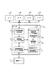
図1は、本発明に係る経路制御システム100の全体構成及び制御サーバ1の機能的構成を示す図である。図1に示す様に、経路制御システム100は、制御系に属する制御サーバ1(制御装置に対応)と転送系に属するルータ10〜60(転送装置に対応)とを備えて構成される。
【0024】
制御系と転送系とは、経路制御システム100の物理的な構成要素としての制御サーバ1とルータ10〜60とにより明確に分離されている。制御サーバ1と各ルータ10〜60とは、有線回線を介して相互にデータの送受信が可能である。ルータ10〜60は、別のルータとの間で、有線回線又は有線回線及びルータを介して相互にデータの送受信が可能である。
【0025】
図1に示す様に、制御サーバ1は、経路制御テーブル受信部2(受信手段に対応)と、受信確認通知部3(受信通知手段に対応)と、更新タイマ4と、経路制御テーブル更新部5(更新手段に対応)と、経路制御テーブルDB(Data Base)6と、経路制御部7(制御手段に対応)とを備える。各部はバスを介して、各部の機能に応じた信号の入出力が可能な様に接続されている。
ここで、経路制御テーブルは経路制御情報に対応し、一時的な経路制御テーブルである臨時経路制御テーブルは臨時経路制御情報に対応する。
【0026】
経路制御テーブル受信部2は、各ルータ10〜60から送信される経路制御テーブルを受信する。経路制御テーブル受信部2は、受信された各経路制御テーブルを、その送信元であるルータの識別情報と共に、経路制御テーブル更新部5に出力する。また、経路制御テーブル受信部2は、任意のルータに関する経路制御テーブルの構築が完了したことを検知すると、その旨を示す確認メッセージを当該ルータ宛に送信する。ここで、経路制御テーブルの構築とは、臨時経路制御テーブルを経路制御テーブルとして、後述の経路制御テーブルDB6に新たに「格納」すること、あるいは、既存の臨時経路制御テーブルを新規の臨時経路制御テーブルに「更新」して経路制御テーブルとすることを指す。
【0027】
受信確認通知部3は、経路制御テーブル受信部2により経路制御テーブルが受信されると、その旨を示すメッセージを、臨時経路制御テーブルの送信元であるルータ宛に送信する。
【0028】
更新タイマ4は、経路制御テーブル受信部2がルータから確認メッセージを受信したことを契機として、受信時からの経過時間の計時を開始する。更新タイマ4は、設定時間t1(例えば45秒程度)を保持しており、上記経過時間が設定時間t1に達すると同時に、その旨を経路制御テーブル更新部5に通知する。
【0029】
経路制御テーブル更新部5は、経路制御テーブル受信部2から臨時経路制御テーブルを取得する。経路制御テーブル更新部5は、更新タイマ4から時間経過の通知があると、取得された臨時経路制御テーブルを経路制御テーブルとして格納又は更新することにより、経路制御テーブルDB6の構築を行う。更に、経路制御テーブル更新部5は、経路制御テーブルDB6の構築完了に伴い、経路制御テーブル受信部2に対して上記確認メッセージの送信を指示する。
【0030】
経路制御テーブルDB6には、経路制御テーブル更新部5から入力される臨時経路制御テーブルが経路制御テーブルとして、ルータの識別情報と対応付けられて格納される。
ここで、図2は、経路制御テーブルDB6内のデータ格納例を示す図である。図2に示す様に、経路制御テーブルDB6は、ルータ格納領域6aと経路制御テーブル格納領域6bと経過時間格納領域6cとを有する。
【0031】
ルータ格納領域6aには、経路制御システム100内のルータ10〜60を一意に識別可能な情報(例えば、IPアドレス、MACアドレス等)が格納される。本実施の形態では、簡単の為、各ルータの識別情報として、図面参照符号と同一の番号(10,20,30,…)を例示的に図示する。
【0032】
経路制御テーブル格納領域6bには、経路制御テーブル更新部5から取得された臨時経路制御テーブルが経路制御テーブルとして更新可能に格納される。この経路制御テーブルは、対応するルータにより、トポロジ、隣接ノード、リンクコスト等の経路関連情報を勘案して算出された周知慣用のルーティングテーブルである。図2においては、ルータ10に対応する経路制御テーブルをRT(Routing Table)10と記載し、同様にルータ20,30,…に対応する経路制御テーブルをそれぞれRT20,RT30,…と記載する。
【0033】
経過時間格納領域6cには、上記確認メッセージの送信時からの経過時間(例えば、2秒、5秒、0秒、…)がルータの識別情報と対応付けて格納されている。この経過時間が更新タイマ4の設定時間であるt1を超えた場合に、経路制御テーブル更新部5により経路制御テーブルDB6の構築が為され、次の確認メッセージの送信に伴って、この経過時間は“0”にリセットされる。かかる構築処理は、各ルータの識別情報毎に独立して、臨時経路制御テーブルの送信のあった全てのルータに関して行われる。
【0034】
経路制御部7は、経路制御テーブルDB6内に更新可能に格納されている経路制御テーブル、及びルータの識別情報を参照して、ネットワーク上のパケットが経由するのに最適なルータ及びその通過順序を決定することができる。これにより、パケットの経路制御を行うことができる。
【0035】
図3は、ルータ10の機能的構成を示すブロック図である。図3に示す様に、ルータ10は、経路関連情報送受信部11と、経路制御テーブル生成部12(生成手段に対応)と、経路制御テーブル格納部13と、臨時経路制御テーブル送信部14(送信手段に対応)と、確認応答タイマ15とを備える。各部はバスを介して、各部の機能に応じた信号の入出力が可能な様に接続されている。
【0036】
経路関連情報送受信部11は、隣接ルータ20,30,40,50から、各ルータの経路関連情報を受信し、これらの情報を経路制御テーブル生成部12に出力する。ここで、経路関連情報とは、経路制御システム100が構築されたネットワークに関する情報であり、経路制御テーブルの生成に際して使用されるものである。経路関連情報は、例えば、ネットワークトポロジ、対象となるルータの隣接ノード、リンクコスト等である。
【0037】
経路制御テーブル生成部12は、経路関連情報送受信部11から入力された経路関連情報に基づいて臨時経路制御テーブルを生成すると共に、このテーブルを経路制御テーブル格納部13に格納する。また、経路制御テーブル生成部12は、臨時経路制御テーブルの送信に対する確認メッセージが、送信時から所定時間内に受信された場合に、経路制御テーブル格納部13内の臨時経路制御テーブル13aを経路制御テーブル13bに更新する。
【0038】
経路制御テーブル格納部13は、経路制御テーブル生成部12から入力された臨時経路制御テーブルを更新可能に保持する。また、経路制御テーブル格納部13は、経路制御テーブル生成部12により既存の臨時経路制御テーブルが更新されると、更新後の臨時経路制御テーブルである経路制御テーブルを格納する。
【0039】
臨時経路制御テーブル送信部14は、経路制御テーブル生成部12から入力された経路制御テーブルをルータ10の識別情報と共に制御サーバ1宛に送信する。また、臨時経路制御テーブル送信部14は、制御サーバ1から確認メッセージを受信する。更に、臨時経路制御テーブル送信部14は、確認応答タイマ15から通知される経過時間を監視し、後述の設定時間t2内に確認メッセージを受信した場合には、経路制御テーブル生成部12に対して臨時経路制御テーブルの更新を指示する。
【0040】
確認応答タイマ15は、臨時経路制御テーブル送信部14が臨時経路制御テーブルを送信したことを検知すると、送信時からの経過時間の計時を開始する。確認応答タイマ15は、設定時間t2(例えば15秒程度)を保持しており、上記経過時間が設定時間t2に到達した場合には、その旨を経過時間と共に臨時経路制御テーブル送信部14に通知する。
【0041】
以上、ルータ10の構成を説明した。他のルータ20〜60に関しては、ルータ10と設置位置は異なるものの、基本的構成を同一とするので、その構成の図示及び詳細な説明は省略する。
【0042】
次に、経路制御システム100の動作を説明する。併せて、本発明に係る経路制御方法の各ステップについて説明する。
まず、図4を参照して、経路制御システム100を構成する各ルータにより実行される経路制御テーブル提供処理について説明する。本実施の形態では、隣接ルータ数が最も多いルータ10が実行する経路制御テーブル提供処理について代表的に説明するが、本経路制御テーブル提供処理は、ルータ20〜60が実行することも勿論可能である。
【0043】
S1では、ルータ10は経路関連情報の送信を待機する。隣接のルータ20,30,40,50から送信された経路関連情報が、ルータ10の経路関連情報送受信部11により受信されると(S1;Yes)、各隣接ルータの経路関連情報を基にして、経路制御テーブル生成部12により臨時経路制御テーブルが生成される。この生成には、一旦生成された臨時経路制御テーブルの内容変更や同一のルータに関する臨時経路制御テーブルの生成(再生成)を含む。生成された臨時経路制御テーブルは、経路制御テーブル格納部13内に一時的に保持される(S2)。
【0044】
S3では、S2で生成された臨時経路制御テーブルが、ルータ10の識別情報と共に、臨時経路制御テーブル送信部14により制御サーバ1宛に送信される。臨時経路制御テーブルの送信と同時に、確認応答タイマ15の計時が開始される(S4)。
【0045】
臨時経路制御テーブル送信部14は、上記計時の開始に伴って、制御サーバ1からの確認メッセージの送信を待機する(S5)。この確認メッセージは、制御サーバ1が経路制御テーブルの構築が完了したことを示す肯定応答(ACK:ACKnowledgement)であり、ルータ10は、この確認メッセージを受信することにより、その時点における臨時経路制御テーブルを経路制御テーブルに更新する。この処理を以って、制御サーバ1は、ルータ10の経路制御が可能となる。
【0046】
制御サーバ1から送信された確認メッセージが、ルータ10の臨時経路制御テーブル送信部14により受信されると(S5;Yes)、経路制御テーブル生成部12により、経路制御テーブル格納部13内に現在格納されている臨時経路制御テーブルが経路制御テーブルとして格納される(S6)。この処理の完了に伴い、ルータ10は、制御サーバ1による経路制御が実行可能な状態となる。S6の処理完了後、ルータ10は更なる経路関連情報の送信を待機すべく、S1に戻り、S1以降の処理が再実行される。
【0047】
一方、S5において、上記確認メッセージが、ルータ10の臨時経路制御テーブル送信部14により受信されない場合には(S5;No)、確認応答タイマ15の経過時間が確認される(S7)。当該確認の結果、確認応答タイマ15の経過時間が設定時間t2を超えていなければ(タイムアウトでなければ)、S5に戻り、上述したS5以降の処理が再び実行される。
【0048】
これに対して、確認メッセージが受信されず(S5;No)、かつ、確認応答タイマ15の経過時間が設定時間t2を超えた場合には(S7;Yes)、S1に戻り、S1以降の処理が再度実行される。
【0049】
上述した一連の経路制御テーブル提供処理を実行することにより、ルータ10は、制御サーバ1宛に送信した臨時経路制御テーブルの確認メッセージが設定時間t2の経過を待たずに返信された場合にのみ、当該臨時経路制御テーブルを経路制御テーブルとして格納する。これにより、ルータ10と制御サーバ1との間で、随時同一の経路制御テーブルが保持される。したがって、ルータ10の稼動状況が即時的に反映された精確な経路制御を実現できる。
【0050】
続いて、図5を参照して、制御サーバ1により実行される経路制御テーブルDB構築処理について説明する。
T1では、制御サーバ1は、ルータ10による経路制御テーブルの受信を待機する。図4のS3にてルータ10から送信された経路制御テーブルが、その送信元であるルータ10の識別情報と共に、経路制御テーブル受信部2により受信されると(T1;Yes)、T2に移行する。
【0051】
T2では、更新タイマ4の計時処理が開始されている場合に更新タイマ4の経過時間が確認される。すなわち、経路制御テーブル提供処理の一巡目の時点では更新タイマ4の計時が依然開始されていないので、T2の処理は省略されT3に移行する。二巡目以降においては、後述のT5にて既に更新タイマ4の計時が開始されているので、経路制御テーブル更新部5により更新タイマ4の経過時間が確認される。
【0052】
当該確認の結果、更新タイマ4の経過時間が設定時間t1を超えている場合(タイムアウトである場合)には、経路制御テーブル更新部5により、T1で受信された臨時経路制御テーブルが経路制御テーブルとして格納又は更新される(T3)。例えば、経路制御テーブルDB6内に、ルータ10に対応する経路制御テーブルが格納されていない場合には、当該経路制御テーブルの格納領域が形成され格納される。ルータ10に対応する経路制御テーブルが経路制御テーブルDB6内に既に格納されている場合には、当該経路制御テーブルに代わり、T1で受信された臨時経路制御テーブルが新たな経路制御テーブルとして格納される。格納又は更新処理の完了に伴い、制御サーバ1は、パケットの経路制御を実行可能な状態になる。
【0053】
一方、制御サーバ1が臨時経路制御テーブルの受信確認を送信した時点で、更新タイマ4の経過時間が設定時間t1を超えていない場合には(T2;No)、T1に戻り、T1以降の処理が再度実行される。
【0054】
T4では、経路制御テーブル受信部2により、経路制御テーブルの格納又は更新が検知されたことに伴い、臨時経路制御テーブルの送信元であるルータ10に向けて確認メッセージが送信される。この確認メッセージは、図4に示したS5にて、ルータ10の臨時経路制御テーブル送信部14により受信される。
確認メッセージの送信と同時に更新タイマ4の計時が開始されると(T5)、制御サーバ1は、更なる臨時経路制御テーブルの送信を待機すべく、T1に戻り、T1以降の処理が再実行される。
【0055】
上述した一連の経路制御テーブルDB構築処理を制御サーバ1が実行することにより、ルータ10〜60が生成した複数の経路制御テーブルが経路制御テーブルDB6に集約される。制御サーバ1の経路制御部7は、この経路制御テーブルDB6を参照してパケットの経路制御を行う。すなわち、制御サーバ1は、ネットワーク上の機器数の把握や稼動状況の集中管理を行うことにより、システムの輻輳状況やパケットの宛先である移動機の移動状態に応じて、適切なルータに対して適切なパケット転送処理を指示することができる。これにより、既存のルータの構成に大幅な変更を施すことなく、輻輳制御などのQoS(Quality of Service)を考慮したネットワーク管理、あるいは、高機能なハンドオフが実現される。
【0056】
また、経路制御テーブルの新規格納時又は前回の更新時から充分な時間が経過していない内に、臨時経路制御テーブルがルータから送信された場合には、当該ルータが、経路制御テーブルを頻繁に更新していることが予測される。この点を考慮して、かかる場合には、制御サーバ1は、経路制御テーブルDB6の更新、及びルータに対する確認メッセージの送信を行わない。すなわち、経路制御テーブルの経時的変動が激しい場合には、一定時間の経過を待った後に、実際に経路制御に用いる情報を確定する。これにより、経路関連情報の揺らぎが極力排除された、より精確な経路制御が可能となる。
【0057】
(第2の実施形態)
以下、本発明の第2の実施形態について、図面を参照して詳細に説明する。
第1の実施形態では、経路制御テーブルの更新タイマを制御系としての制御サーバが有するものとした。これに対して、本実施の形態では、経路制御テーブルの更新タイマを転送系としてのルータが有するものとすることにより、制御サーバとルータ間における不要な経路制御テーブルの送受信を減らし、経路制御システム内の通信負荷、及び制御サーバの処理負荷を低減する。
【0058】
以下、本実施形態における経路制御システムについて詳細に説明する。
図6は、本発明に係る経路制御システム200の全体構成及び制御サーバ101の機能的構成を示す図である。図6に示す様に、経路制御システム200は、制御系に属する制御サーバ101(制御装置に対応)と転送系に属するルータ110〜160(転送装置に対応)とを備えて構成される。
【0059】
制御系と転送系とは、経路制御システム200の物理的な構成要素としての制御サーバ101とルータ110〜160とにより明確に分離されている。制御サーバ101と各ルータ110〜160とは、有線回線を介して相互にデータの送受信が可能である。各ルータ110〜160は、別のルータとの間で、有線回線又は有線回線及びルータを介して相互にデータの送受信が可能である。
【0060】
図6は、第2の実施形態における制御サーバの機能的構成を示すブロック図である。当該制御サーバの構成は、計時手段としての更新タイマを備えない点を除き、第1の実施形態において詳述した制御サーバ1の構成と同様である。したがって、各構成要素には同列(末尾の数字が同一)の符合を付すと共に、その説明は省略する。
【0061】
すなわち、制御サーバ101は、図6に示す様に、経路制御テーブル受信部102(受信手段に対応)と、受信確認通知部103(受信通知手段に対応)と、経路制御テーブル更新部105(更新手段に対応)と、経路制御テーブルDB106と、経路制御部107(制御手段に対応)とを備えて構成される。各部は、図1に示した経路制御テーブル受信部2と、受信確認通知部3と、経路制御テーブル更新部5と、経路制御テーブルDB6と、経路制御部7とにそれぞれ相当する。
【0062】
図7は、第2の実施形態におけるルータ110の機能的構成を示すブロック図である。ルータ110の構成は、第1の実施形態において詳述したルータ10の構成と類似するので、各構成要素には同列(末尾の数字が同一)の符合を付しその説明は省略すると共に、第1実施形態との差異について詳述する。
【0063】
ルータ110は、図7に示す様に、経路関連情報送受信部111と、経路制御テーブル生成部112(生成手段に対応)と、経路制御テーブル格納部113と、臨時経路制御テーブル送信部114(送信手段に対応)と、確認応答タイマ115と、更新タイマ116とを備える。各部はバスを介して、各部の機能に応じた信号の入出力が可能な様に接続されている。更新タイマ116以外の各部は、経路関連情報送受信部11と、経路制御テーブル生成部12と、経路制御テーブル格納部13と、臨時経路制御テーブル送信部14と、確認応答タイマ15とにそれぞれ相当する。
【0064】
本実施の形態におけるルータに特有の構成要素である更新タイマ116(図7中太線に示すブロック)は、臨時経路制御テーブルが経路制御テーブルとして経路制御テーブル格納部113に格納されたことを契機として、格納時からの経過時間の計時を開始する。更新タイマ116は、設定時間t3(例えば45秒程度)を保持しており、上記経過時間が設定時間t3に達したのと同時に、その旨を経路制御テーブル生成部112に通知する。
【0065】
以上、ルータ110の構成を説明した。他のルータ120〜160に関しては、ルータ110と設置位置は異なるものの、基本的構成を同一とする。したがって、その構成の図示及び詳細な説明は省略する。
【0066】
次に、図8及び図9を参照して、経路制御システム200の動作を説明する。併せて、本発明に係る経路制御方法の各ステップについて説明する。
まず、ルータ110により実行される経路制御テーブル提供処理は、第1の実施形態において詳述した経路制御テーブル提供処理(図4参照)と基本的に同様である。具体的には、図8のS11〜S17の各ステップは、図4に示したS1〜S7の各ステップにそれぞれ相当する。
【0067】
以下、本実施の形態におけるルータに特有のステップであるS18及びS19(図8中太線で示す処理)について説明する。すなわち、S18では、更新タイマ116の計時処理が開始されている場合に更新タイマ116の経過時間が確認される。すなわち、経路制御テーブル提供処理の一巡目の時点では依然として更新タイマ116の計時が開始されていないので、S18の処理は省略されS12に移行する。二巡目以降においては、後述のS19にて既に更新タイマ116の計時が開始されているので、経路制御テーブル生成部112により更新タイマ116の経過時間が確認される。
【0068】
当該確認の結果、更新タイマ116の経過時間がその設定時間t3を超えている場合(タイムアウトである場合)には、経路制御テーブル生成部112により、S11で受信された経路関連情報を基に臨時経路制御テーブルが生成及び保持される(S12)。生成には、一旦生成された臨時経路制御テーブルの内容変更や同一のルータに関する臨時経路制御テーブルの生成(再生成)を含む。
【0069】
一方、更新タイマ116の経過時間が設定時間t3を超えていない場合には(S18;No)、S11に戻り、S11以降の処理が再度実行される。
また、S19では、臨時経路制御テーブルの更新と同時に更新タイマ116の計時が開始され、ルータ110は更なる経路関連情報の送信を待機すべく、S11に戻り、S11以降の処理が再実行される。
【0070】
続いて、制御サーバ101により実行される経路制御テーブルDB構築処理は、第1の実施形態において詳述した経路制御テーブルDB構築処理(図5参照)と基本的に同様である。具体的には、図9のT11,T14,T15の各ステップは、図5に示したT1,T3,T4の各ステップにそれぞれ相当する。すなわち、本実施の形態における制御サーバ101は、確認メッセージ送信からの経過時間に拘わらず、受信した全ての臨時経路制御テーブルを経路制御テーブルDB6の構築に使用する。
【0071】
以上説明した様に、第2の実施形態における経路制御システム200によれば、ルータによる臨時経路制御テーブルの生成及び送信は、受信された全ての経路関連情報に関して逐次実行されずに、臨時経路制御テーブルの更新から所定時間の経過を待って開始される。したがって、経路制御テーブルDB106の構築に使用されることのない臨時経路制御テーブルが、ルータから制御サーバ101に送信されることがない。その結果、経路制御システム200における通信負荷が低減される。また、制御サーバ101は、更新タイマを備える必要がないので簡易な構成になると共に、計時処理に伴う処理負荷が軽減される。
【0072】
【発明の効果】
本発明によれば、ネットワーク上の経路制御情報を集約して、パケットの経路制御を効率的かつ精確に行うことが可能となる。
【図面の簡単な説明】
【図1】第1の実施形態における経路制御システムの全体構成及び制御サーバの機能的構成を示す図である。
【図2】経路制御テーブルDBのデータ格納例を示す図である。
【図3】第1の実施形態におけるルータの機能的構成を示すブロック図である。
【図4】第1の実施形態における経路制御テーブル提供処理を説明するためのフローチャートである。
【図5】第1の実施形態における経路制御テーブルDB構築処理を説明するためのフローチャートである。
【図6】第2の実施形態における経路制御システムの全体構成及び制御サーバの機能的構成を示す図である。
【図7】第2の実施形態におけるルータの機能的構成を示すブロック図である。
【図8】第2の実施形態における経路制御テーブル提供処理を説明するためのフローチャートである。
【図9】第2の実施形態における経路制御テーブルDB構築処理を説明するためのフローチャートである。
【符号の説明】
1,101…制御サーバ、2,102…経路制御テーブル受信部、3,103…受信確認通知部、4…更新タイマ、5,105…経路制御テーブル更新部、6,106…経路制御テーブルDB、7,107…経路制御部、10,20,30,40,50,60,110,120,130,140,150,160…ルータ、11,111…経路関連情報送受信部、12,112…経路制御テーブル生成部、13,113…経路制御テーブル格納部、13a,113a…臨時経路制御テーブル、61,1061,13b,113b…経路制御テーブル、14,114…臨時経路制御テーブル送信部、15,115…確認応答タイマ、116…更新タイマ、100,200…経路制御システム[0001]
TECHNICAL FIELD OF THE INVENTION
The present invention relates to a route control system, a route control device, and a route control method.
[0002]
[Prior art]
2. Description of the Related Art Conventionally, in a packet communication system using a network, a router transfers a packet based on unique routing control (routing) information created by itself. Normally, each router existing in the system establishes a packet communication path by exchanging path control information with another router. For this reason, the route control function and the packet transfer function are mixed on such a router, and the router does not simultaneously grasp all the route control information on the packet communication system (for example, see Non-Patent Document 1). .
[0003]
Also, depending on the routing method, a router may recalculate its own routing control information every time it exchanges routing control-related information with an adjacent router, so that a considerable load may be applied to the calculation of routing control information. (For example, see Non-Patent
[0004]
[Non-patent document 1]
Mark Miller, Implementing IPv6 second edition, 2000, pp. 44-47
[Non-patent document 2]
RFC 1058, Routing Information Protocol
[0005]
[Problems to be solved by the invention]
In the conventional packet communication system, the route control function and the packet transfer function are not clearly separated, so that the route control of the packet on the network becomes complicated, and it is difficult to expand or reduce the route control function. There were some problems. Further, since each router transfers a packet based on its own path control information, it cannot accurately reflect the number of routers on the network and the operation status of each router in the path control of the packet.
[0006]
Therefore, in order to accurately control the route of a packet, it is conceivable that an edge router such as a gateway router or an access router located at the end of the network performs the overall route control. However, in such a method, the processing load associated with path control and packet transfer is concentrated on some routers in the system, and cannot be efficiently distributed to each router.
[0007]
Therefore, an object of the present invention is to perform routing control of packets efficiently and accurately by aggregating routing control information scattered on a network.
[0008]
[Means for Solving the Problems]
In order to solve the above-described problems, a routing control system according to the present invention is a routing control system including a plurality of transfer devices that transfer a packet on a network, and a control device that controls a transfer route of the packet. The plurality of transfer devices are configured to generate temporary routing control information (for example, a temporary routing control table described later) of the packet, and to transmit the temporary routing control information generated by the generating unit to the control device. Means. The control device, receiving means for receiving a plurality of temporary path control information transmitted by the transmission means of the plurality of transfer devices, and using the plurality of temporary path control information received by the receiving means of the packet Control means for controlling the transfer path.
[0009]
A route control device according to the present invention is a route control device connected to a plurality of transfer devices for transferring a packet on a network and controlling a transfer route of the packet, wherein the plurality of transfer devices transmitted from the plurality of transfer devices are provided. A receiving unit that receives the temporary routing control information; and a control unit that controls a transfer route of the packet using the plurality of temporary routing control information received by the receiving unit.
[0010]
In the routing method according to the present invention, the generation unit of the plurality of transfer devices generates the temporary routing control information of the packet, and the transmission unit of the plurality of transfer devices generates the temporary routing information in the generation step. A transmitting step of transmitting path control information to a control device, a receiving step of receiving the plurality of temporary path control information transmitted in the transmitting step, and a control unit of the control device, Controlling the transfer path of the packet using the plurality of pieces of temporary path control information received in the receiving step.
[0011]
According to these inventions, the temporary route control information of the packet is generated by the plurality of transfer devices and then transmitted to the control device. The control device controls the transfer route of the packet based on the plurality of pieces of temporary route control information. In other words, according to these inventions, the temporary routing control information of the forwarding devices (for example, routers) scattered on the network is aggregated in the control device, so that the routing control function and the packet forwarding function in the routing control system are controlled by And a transfer device.
[0012]
This facilitates routing control of packets on the network and expansion and contraction of functions related to routing control. Also, the control device refers to the temporary route control information collected from each transfer device, and performs packet route control after comprehensively grasping the number of transfer devices on the network and the operation status of each transfer device. be able to. As a result, it is possible to efficiently and accurately control the path of the packet as compared with the case where each transfer apparatus individually performs the path control.
[0013]
Further, in the routing control system according to the present invention, preferably, the transmission unit of the transfer device transmits the temporary routing control information to the control device when the temporary routing control information of the packet is changed or regenerated. .
Further, in the routing method according to the present invention, preferably, in the transmitting step, the transmitting unit of the transfer device, when the temporary routing control information of the packet is changed or regenerated, the temporary routing control information Transmit to the control device.
[0014]
According to these inventions, not only when the temporary routing control information of the packet is generated, but also when the temporary routing control information is changed or regenerated, the temporary routing control information is transmitted from the transfer device to the control device. Sent to Thus, even when the temporary path control information once generated by the transfer device is updated, the same temporary path control information is always held in the transfer device and the control device. Therefore, the control device can accurately grasp the dynamically changing temporary path control information in real time, and can promptly and flexibly reflect the information in the path control processing. As a result, it is possible to efficiently and accurately perform packet routing.
[0015]
Preferably, in the path control system according to the present invention, when the temporary path control information is transmitted, the temporary path control information is transmitted to a transfer device that is a transmission source of the temporary path control information. There is further provided a reception notifying means for notifying the reception.
Further, in the path control method according to the present invention, preferably, when the temporary path control information is transmitted, the temporary path control information is transmitted to the transfer device that is the transmission source of the temporary path control information, The method further includes a reception notifying step of notifying that it has been received.
[0016]
According to these inventions, when the temporary route control information is transmitted from the transfer device to the control device, the fact that the control device has received the temporary route control information is notified to the transfer device that is the transmission source of the temporary route control information. Notified. By receiving this notification, the transfer apparatus can easily confirm that the temporary path control information generated and transmitted by the transfer apparatus is surely reflected in the path control of the packet. At the same time, the transfer device can easily confirm that there is no need to retransmit the temporary routing information.
[0017]
Preferably, in the route control system according to the present invention, after the first temporary route control information received by the receiving unit is stored, the control unit may control the receiving unit by a predetermined time. After updating the first temporary route control information to the newly received second temporary route control information, storing the second temporary route control information as route control information (for example, a route control table described later). Updating means for storing in the means.
[0018]
Further, in the route control method according to the present invention, preferably, after the first temporary route control information received in the receiving step is stored, the control device performs the receiving step in accordance with a lapse of a predetermined time. Updating the first temporary path control information to the second temporary path control information newly received in step (a), and storing the second temporary path control information as path control information in storage means. In addition.
[0019]
According to these inventions, when a predetermined time has elapsed after the received first temporary route control information is stored, and when the second temporary route control information is newly received from the same transfer device, , The existing first temporary path control information is updated to the second temporary path control information. Then, the second temporary path control information is stored as path control information. That is, when the temporary route control information is frequently transmitted from the transfer device, the process waits for a certain period of time and does not intentionally update the route control information. Therefore, even when the transfer device frequently changes and transmits the temporary route control information, the temporary route control information is not changed at any time on the control device side. This suppresses the route control information from fluctuating frequently in a short period of time in the control device, and maintains the consistency of the route control information. As a result, it is possible to perform packet routing with high accuracy.
[0020]
In the routing control system according to the present invention, when the routing control information is updated by the updating unit, the control device notifies the transfer device that the routing control information has been updated (corresponding to a confirmation message described below). ) May be further provided.
[0021]
In the routing control method according to the present invention, when the routing control information is updated in the updating step, the control device informs the transfer device that the routing control information has been updated (a confirmation message to be described later) The method may further include an update notification step of notifying (response).
[0022]
According to these inventions, when the route control information is updated by the control device, the fact is notified to the transfer device. By receiving the notification, the transfer device can easily and quickly recognize that the transmitted temporary routing control information is reflected in the routing. Further, based on this recognition, the transfer device can execute the process of replacing the existing temporary routing control information with the new routing control information to obtain the routing control information.
[0023]
BEST MODE FOR CARRYING OUT THE INVENTION
(1st Embodiment)
Hereinafter, a first embodiment of the present invention will be described in detail with reference to the drawings.
FIG. 1 is a diagram showing an overall configuration of a
[0024]
The control system and the transfer system are clearly separated by the control server 1 as a physical component of the
[0025]
As shown in FIG. 1, the control server 1 includes a routing control table receiving unit 2 (corresponding to a receiving unit), a reception confirmation notifying unit 3 (corresponding to a receiving notifying unit), an
Here, the path control table corresponds to the path control information, and the temporary path control table, which is a temporary path control table, corresponds to the temporary path control information.
[0026]
The routing control
[0027]
When the routing control
[0028]
The
[0029]
The routing
[0030]
The temporary routing control table input from the routing control
Here, FIG. 2 is a diagram illustrating an example of data storage in the routing control table DB6. As shown in FIG. 2, the routing
[0031]
The
[0032]
The temporary routing control table acquired from the routing control
[0033]
The elapsed time storage area 6c stores the elapsed time (for example, 2 seconds, 5 seconds, 0 seconds,...) From the transmission of the confirmation message in association with the router identification information. When this elapsed time exceeds t1, which is the set time of the
[0034]
The
[0035]
FIG. 3 is a block diagram illustrating a functional configuration of the
[0036]
The route-related information transmitting / receiving unit 11 receives the route-related information of each router from the
[0037]
The route control
[0038]
The routing
[0039]
The temporary routing control
[0040]
When the
[0041]
The configuration of the
[0042]
Next, the operation of the
First, with reference to FIG. 4, a description will be given of a routing control table providing process executed by each router configuring the
[0043]
In S1, the
[0044]
In S3, the temporary path control table generated in S2 is transmitted to the control server 1 by the temporary path control
[0045]
The temporary route control
[0046]
When the confirmation message transmitted from the control server 1 is received by the temporary routing control
[0047]
On the other hand, if the confirmation message is not received by the temporary routing
[0048]
On the other hand, if the confirmation message is not received (S5; No) and the elapsed time of the
[0049]
By executing the above-described series of routing control table providing processes, the
[0050]
Next, the routing control table DB construction processing executed by the control server 1 will be described with reference to FIG.
At T1, the control server 1 waits for the
[0051]
At T2, the elapsed time of the
[0052]
As a result of the confirmation, if the elapsed time of the
[0053]
On the other hand, if the elapsed time of the
[0054]
At T4, the storage or update of the routing control table is detected by the routing control
When the counting of the
[0055]
When the control server 1 executes the above-described series of routing control table DB construction processing, a plurality of routing control tables generated by the
[0056]
In addition, if the temporary routing control table is transmitted from the router before a sufficient time has elapsed since the new storing or the previous updating of the routing control table, the router frequently updates the routing control table. It is expected that it has been updated. Considering this point, in such a case, the control server 1 does not update the routing control table DB6 and transmit a confirmation message to the router. That is, when the route control table has a large variation over time, the information actually used for the route control is determined after a predetermined time has passed. This enables more accurate route control in which fluctuations in route-related information are eliminated as much as possible.
[0057]
(Second embodiment)
Hereinafter, a second embodiment of the present invention will be described in detail with reference to the drawings.
In the first embodiment, the control server as the control system has the update timer of the routing control table. On the other hand, in the present embodiment, the router as the transfer system has the routing control table update timer, thereby reducing unnecessary transmission and reception of the routing control table between the control server and the router. Communication load within the server and the processing load on the control server.
[0058]
Hereinafter, the route control system according to the present embodiment will be described in detail.
FIG. 6 is a diagram showing the overall configuration of the
[0059]
The control system and the transfer system are clearly separated by the
[0060]
FIG. 6 is a block diagram illustrating a functional configuration of a control server according to the second embodiment. The configuration of the control server is the same as the configuration of the control server 1 described in detail in the first embodiment, except that the control server does not include an update timer as a clock unit. Therefore, each component is denoted by the same reference numeral (the same number at the end) and the description thereof is omitted.
[0061]
That is, as shown in FIG. 6, the
[0062]
FIG. 7 is a block diagram illustrating a functional configuration of the
[0063]
As shown in FIG. 7, the
[0064]
The update timer 116 (the block indicated by the thick line in FIG. 7), which is a component specific to the router in the present embodiment, is triggered by the fact that the temporary routing control table is stored in the routing control
[0065]
The configuration of the
[0066]
Next, the operation of the
First, the routing control table providing process executed by the
[0067]
Hereinafter, steps S18 and S19 (the processing indicated by the thick line in FIG. 8) which are steps specific to the router according to the present embodiment will be described. That is, in S18, the elapsed time of the
[0068]
As a result of the confirmation, if the elapsed time of the
[0069]
On the other hand, if the elapsed time of the
In S19, the
[0070]
Subsequently, the routing control table DB construction process executed by the
[0071]
As described above, according to the
[0072]
【The invention's effect】
ADVANTAGE OF THE INVENTION According to this invention, it becomes possible to aggregate routing control information on a network and to perform routing control of a packet efficiently and accurately.
[Brief description of the drawings]
FIG. 1 is a diagram illustrating an overall configuration of a route control system and a functional configuration of a control server according to a first embodiment.
FIG. 2 is a diagram illustrating an example of data storage in a routing control table DB.
FIG. 3 is a block diagram illustrating a functional configuration of a router according to the first embodiment.
FIG. 4 is a flowchart illustrating a route control table providing process according to the first embodiment.
FIG. 5 is a flowchart illustrating a routing control table DB construction process according to the first embodiment.
FIG. 6 is a diagram illustrating an overall configuration of a route control system and a functional configuration of a control server according to a second embodiment.
FIG. 7 is a block diagram illustrating a functional configuration of a router according to the second embodiment.
FIG. 8 is a flowchart illustrating a route control table providing process according to the second embodiment.
FIG. 9 is a flowchart illustrating a routing control table DB construction process according to the second embodiment.
[Explanation of symbols]
1, 101: control server, 2, 102: routing control table receiving unit, 3, 103: reception confirmation notifying unit, 4: update timer, 5, 105: routing control table updating unit, 6, 106: routing control table DB, 7, 107: route control unit, 10, 20, 30, 40, 50, 60, 110, 120, 130, 140, 150, 160 ... router, 11, 111: route related information transmitting / receiving unit, 12, 112: route control Table generation units, 13, 113: route control table storage units, 13a, 113a: temporary route control tables, 61, 1061, 13b, 113b: route control tables, 14, 114: temporary route control table transmission units, 15, 115 ... Acknowledgment timer, 116: update timer, 100, 200: route control system
Claims (9)
前記複数の転送装置は、
前記パケットの臨時経路制御情報を生成する生成手段と、
前記生成手段により生成された臨時経路制御情報を前記制御装置に送信する送信手段とを備え、
前記制御装置は、
前記複数の転送装置の送信手段により送信された複数の臨時経路制御情報を受信する受信手段と、
前記受信手段により受信された複数の臨時経路制御情報を使用して前記パケットの転送経路を制御する制御手段と
を備えることを特徴とする経路制御システム。A route control system including a plurality of transfer devices that transfer a packet on a network and a control device that controls a transfer route of the packet,
The plurality of transfer devices,
Generating means for generating temporary routing information of the packet;
Transmitting means for transmitting the temporary path control information generated by the generating means to the control device,
The control device includes:
Receiving means for receiving a plurality of temporary route control information transmitted by the transmitting means of the plurality of transfer devices,
Control means for controlling a transfer path of the packet using a plurality of pieces of temporary path control information received by the receiving means.
前記受信手段により受信された第1の臨時経路制御情報が格納された後、所定時間の経過に伴って、前記受信手段により新たに受信された第2の臨時経路制御情報に前記第1の臨時経路制御情報を更新した上で、前記第2の臨時経路制御情報を経路制御情報として格納手段に格納する更新手段を更に備えることを特徴とする請求項1に記載の経路制御システム。The control device includes:
After the first temporary route control information received by the receiving unit is stored, the first temporary route control information newly received by the receiving unit is added to the first temporary route control information as the predetermined time elapses. The route control system according to claim 1, further comprising an update unit that updates the route control information and stores the second temporary route control information in the storage unit as the route control information.
前記複数の転送装置から送信された複数の臨時経路制御情報を受信する受信手段と、
前記受信手段により受信された複数の臨時経路制御情報を使用して前記パケットの転送経路を制御する制御手段と
を備えることを特徴とする経路制御装置。A route control device connected to a plurality of transfer devices for transferring a packet on a network and controlling a transfer route of the packet,
Receiving means for receiving a plurality of temporary route control information transmitted from the plurality of transfer devices,
Control means for controlling a transfer path of the packet using a plurality of pieces of temporary path control information received by the receiving means.
前記複数の転送装置の送信手段が、前記生成ステップにて生成された臨時経路制御情報を制御装置に送信する送信ステップと、
前記制御装置の受信手段が、前記送信ステップにて送信された複数の臨時経路制御情報を受信する受信ステップと、
前記制御装置の制御手段が、前記受信ステップにて受信された複数の臨時経路制御情報を使用して前記パケットの転送経路を制御する制御ステップと
を含むことを特徴とする経路制御方法。Generating means for generating the temporary routing information of the packet, wherein the generating means of the plurality of transfer devices generates;
A transmitting step of transmitting the temporary path control information generated in the generating step to the control device,
A receiving step of receiving the plurality of temporary route control information transmitted in the transmitting step,
A control step of controlling the transfer route of the packet by using a plurality of pieces of temporary route control information received in the receiving step.
Priority Applications (6)
| Application Number | Priority Date | Filing Date | Title |
|---|---|---|---|
| JP2002308770A JP2004147021A (en) | 2002-10-23 | 2002-10-23 | Route control system, route controller and route control method |
| US10/689,702 US7535896B2 (en) | 2002-10-23 | 2003-10-22 | Routing control system, routing control device, and routing control method |
| EP20030024466 EP1414199B1 (en) | 2002-10-23 | 2003-10-23 | Routing control system, routing control device, and routing control method |
| DE2003614821 DE60314821T2 (en) | 2002-10-23 | 2003-10-23 | Routing control system, routing control device, and routing control method |
| EP20070012303 EP1830524A1 (en) | 2002-10-23 | 2003-10-23 | Routing control system, routing control device and routing control method |
| CNB2003101025686A CN100484015C (en) | 2002-10-23 | 2003-10-23 | Route control system, route control device and route control method |
Applications Claiming Priority (1)
| Application Number | Priority Date | Filing Date | Title |
|---|---|---|---|
| JP2002308770A JP2004147021A (en) | 2002-10-23 | 2002-10-23 | Route control system, route controller and route control method |
Related Child Applications (1)
| Application Number | Title | Priority Date | Filing Date |
|---|---|---|---|
| JP2007026033A Division JP4390812B2 (en) | 2007-02-05 | 2007-02-05 | Route control system, route control device, and route control method |
Publications (1)
| Publication Number | Publication Date |
|---|---|
| JP2004147021A true JP2004147021A (en) | 2004-05-20 |
Family
ID=32064341
Family Applications (1)
| Application Number | Title | Priority Date | Filing Date |
|---|---|---|---|
| JP2002308770A Pending JP2004147021A (en) | 2002-10-23 | 2002-10-23 | Route control system, route controller and route control method |
Country Status (5)
| Country | Link |
|---|---|
| US (1) | US7535896B2 (en) |
| EP (2) | EP1830524A1 (en) |
| JP (1) | JP2004147021A (en) |
| CN (1) | CN100484015C (en) |
| DE (1) | DE60314821T2 (en) |
Cited By (8)
| Publication number | Priority date | Publication date | Assignee | Title |
|---|---|---|---|---|
| JP2006135975A (en) * | 2004-11-01 | 2006-05-25 | Lucent Technol Inc | SEPARATION OF SoftRouter PROTOCOL |
| JP2006135972A (en) * | 2004-11-01 | 2006-05-25 | Lucent Technol Inc | Softrouter separate control network |
| JP2009055609A (en) * | 2007-08-24 | 2009-03-12 | Fujitsu Ltd | System and method for synchronizing packet transfer information |
| US7580418B2 (en) | 2003-12-17 | 2009-08-25 | Nec Corporation | Network, router device, route updating suppression method used for the same, and program thereof |
| US7894439B2 (en) | 2007-10-22 | 2011-02-22 | Fujitsu Limited | Communication device in a virtual private network using a multi protocol label switch |
| WO2013146785A1 (en) * | 2012-03-28 | 2013-10-03 | 日本電気株式会社 | Communication system, communication apparatus, control apparatus, communication apparatus control method and program |
| WO2014027687A1 (en) * | 2012-08-17 | 2014-02-20 | 日本電気株式会社 | Communication system, control information recording device, control device, control information recording method and program |
| JPWO2014174720A1 (en) * | 2013-04-26 | 2017-02-23 | 日本電気株式会社 | Route setting verification device, control method, and program |
Families Citing this family (12)
| Publication number | Priority date | Publication date | Assignee | Title |
|---|---|---|---|---|
| JP4318520B2 (en) * | 2003-09-26 | 2009-08-26 | 富士通株式会社 | Terminal status control system |
| US20060029035A1 (en) * | 2004-03-25 | 2006-02-09 | Chase Christopher J | Method and apparatus for selecting routes for distribution within IP networks |
| WO2006005816A1 (en) * | 2004-06-10 | 2006-01-19 | France Telecom | Method for control management based on a routing protocol |
| US7474632B2 (en) * | 2004-06-30 | 2009-01-06 | International Business Machines Corporation | Method for self-configuring routing devices in a network |
| US8228818B2 (en) | 2005-06-24 | 2012-07-24 | At&T Intellectual Property Ii, Lp | Systems, methods, and devices for monitoring networks |
| CN101212420B (en) | 2006-12-27 | 2010-09-29 | 华为技术有限公司 | Redirector, relay and route information configuration system and update method |
| US20090238109A1 (en) * | 2008-03-18 | 2009-09-24 | Digi International Inc. | Method for qualified route building in a wireless network |
| EP2410698B1 (en) * | 2010-07-19 | 2014-05-07 | Alcatel Lucent | A method for routing and associated routing device and destination device |
| EP2547047B1 (en) * | 2011-07-08 | 2016-02-17 | Alcatel Lucent | Centralized system for routing ethernet packets over an internet protocol network |
| US20130110987A1 (en) * | 2011-10-31 | 2013-05-02 | Electronics And Telecommunications Research Institute | Apparatus and method for providing content location information using ospf opaque lsa |
| US9577979B1 (en) * | 2012-11-14 | 2017-02-21 | Viasat, Inc. | Local name resolution |
| JP6123392B2 (en) * | 2013-03-15 | 2017-05-10 | 富士通株式会社 | Measuring device, measuring method and transmission device |
Family Cites Families (18)
| Publication number | Priority date | Publication date | Assignee | Title |
|---|---|---|---|---|
| JPS4995502A (en) | 1973-01-12 | 1974-09-10 | ||
| US5381403A (en) | 1993-04-02 | 1995-01-10 | Motorola, Inc. | Method for establishing and maintaining system configuration information |
| JPH08265314A (en) | 1995-03-22 | 1996-10-11 | Mitsubishi Electric Corp | Communication network system and network resource reflection method on routing |
| US5987521A (en) | 1995-07-10 | 1999-11-16 | International Business Machines Corporation | Management of path routing in packet communications networks |
| US5970064A (en) | 1997-06-12 | 1999-10-19 | Northern Telecom Limited | Real time control architecture for admission control in communications network |
| US6185556B1 (en) * | 1999-05-04 | 2001-02-06 | Amazon.Com, Inc. | Method and apparatus for changing temporal database |
| US6069895A (en) * | 1997-08-29 | 2000-05-30 | Nortel Networks Corporation | Distributed route server |
| DE19746904B4 (en) | 1997-10-23 | 2004-09-30 | Telefonaktiebolaget L M Ericsson (Publ) | Traffic data evaluation device and associated method for a network with dynamic switching |
| US6496510B1 (en) * | 1997-11-14 | 2002-12-17 | Hitachi, Ltd. | Scalable cluster-type router device and configuring method thereof |
| JP2000174755A (en) * | 1998-12-02 | 2000-06-23 | Fujitsu Ltd | Route selection system |
| JP3623680B2 (en) * | 1999-01-11 | 2005-02-23 | 株式会社日立製作所 | Network system having path verification function, path management apparatus, and exchange |
| JP3645734B2 (en) * | 1999-02-24 | 2005-05-11 | 株式会社日立製作所 | Network relay device and network relay method |
| JP3546764B2 (en) | 1999-07-02 | 2004-07-28 | 日本電気株式会社 | Load balancing server provided in network and node including load balancing server |
| JP3479834B2 (en) | 2000-09-04 | 2003-12-15 | 日本電気株式会社 | Wireless access network routing control system and method |
| KR20020055287A (en) * | 2000-12-28 | 2002-07-08 | 구자홍 | Method for routing a packet of a router device |
| JP2003008627A (en) * | 2001-06-20 | 2003-01-10 | Nec Corp | Data transfer device |
| US7263091B1 (en) * | 2002-05-23 | 2007-08-28 | Juniper Networks, Inc. | Scalable routing system |
| US7509300B2 (en) * | 2002-07-03 | 2009-03-24 | University Of Florida Research Foundation, Inc. | Dynamic IP router tables using highest-priority matching |
-
2002
- 2002-10-23 JP JP2002308770A patent/JP2004147021A/en active Pending
-
2003
- 2003-10-22 US US10/689,702 patent/US7535896B2/en not_active Expired - Fee Related
- 2003-10-23 DE DE2003614821 patent/DE60314821T2/en not_active Expired - Lifetime
- 2003-10-23 EP EP20070012303 patent/EP1830524A1/en not_active Withdrawn
- 2003-10-23 EP EP20030024466 patent/EP1414199B1/en not_active Expired - Fee Related
- 2003-10-23 CN CNB2003101025686A patent/CN100484015C/en not_active Expired - Fee Related
Cited By (9)
| Publication number | Priority date | Publication date | Assignee | Title |
|---|---|---|---|---|
| US7580418B2 (en) | 2003-12-17 | 2009-08-25 | Nec Corporation | Network, router device, route updating suppression method used for the same, and program thereof |
| JP2006135975A (en) * | 2004-11-01 | 2006-05-25 | Lucent Technol Inc | SEPARATION OF SoftRouter PROTOCOL |
| JP2006135972A (en) * | 2004-11-01 | 2006-05-25 | Lucent Technol Inc | Softrouter separate control network |
| JP2009055609A (en) * | 2007-08-24 | 2009-03-12 | Fujitsu Ltd | System and method for synchronizing packet transfer information |
| US7894439B2 (en) | 2007-10-22 | 2011-02-22 | Fujitsu Limited | Communication device in a virtual private network using a multi protocol label switch |
| WO2013146785A1 (en) * | 2012-03-28 | 2013-10-03 | 日本電気株式会社 | Communication system, communication apparatus, control apparatus, communication apparatus control method and program |
| US10454805B2 (en) | 2012-03-28 | 2019-10-22 | Nec Corporation | Communication system, communication apparatus, control apparatus, communication apparatus control method and program |
| WO2014027687A1 (en) * | 2012-08-17 | 2014-02-20 | 日本電気株式会社 | Communication system, control information recording device, control device, control information recording method and program |
| JPWO2014174720A1 (en) * | 2013-04-26 | 2017-02-23 | 日本電気株式会社 | Route setting verification device, control method, and program |
Also Published As
| Publication number | Publication date |
|---|---|
| EP1830524A1 (en) | 2007-09-05 |
| EP1414199A1 (en) | 2004-04-28 |
| US20040136357A1 (en) | 2004-07-15 |
| DE60314821T2 (en) | 2008-05-15 |
| CN100484015C (en) | 2009-04-29 |
| CN1497902A (en) | 2004-05-19 |
| DE60314821D1 (en) | 2007-08-23 |
| US7535896B2 (en) | 2009-05-19 |
| EP1414199B1 (en) | 2007-07-11 |
Similar Documents
| Publication | Publication Date | Title |
|---|---|---|
| JP2004147021A (en) | Route control system, route controller and route control method | |
| JP5754206B2 (en) | Time synchronization method and apparatus in ad hoc network | |
| CN103825822B (en) | A kind of state information transmission method and device of the network equipment | |
| JP5935881B2 (en) | COMMUNICATION SYSTEM, CONTROL DEVICE, AND ITS CONTROL METHOD | |
| JP2010045657A (en) | Frame switching device, communication system, computer program, and address learning method | |
| TW201946489A (en) | Communication method between gateways and wireless gateway system thereof | |
| JP6064989B2 (en) | Control device, communication system, node control method, and program | |
| WO2011118574A1 (en) | Communications system, control device, delay measuring method, and program | |
| JP7079913B2 (en) | Remote control system and method | |
| JP2008147925A (en) | Network band reservation method and communication equipment for the method | |
| JP2008072521A (en) | Equipment, method and program for communication | |
| JP6174454B2 (en) | Multi-hop network system and control method of multi-hop network system | |
| JP4390812B2 (en) | Route control system, route control device, and route control method | |
| JP4630298B2 (en) | Function distributed communication apparatus, component element coupling control method, and program | |
| JP6063826B2 (en) | Route confirmation device, route confirmation system, route confirmation method, and program | |
| JP5375833B2 (en) | Node device, route control method, route calculation system, and route calculation device | |
| WO2018025491A1 (en) | Control network system and node device thereof | |
| JP5866811B2 (en) | Network device, transmission destination inquiry method, and transmission destination inquiry program | |
| JP4853862B2 (en) | Communication device | |
| JP4609862B2 (en) | Network relay method, network element, and network relay system | |
| JP3786757B2 (en) | Network communication system and communication method thereof | |
| JP6244567B2 (en) | Network management system | |
| JP2004248257A (en) | Communication system and terminal | |
| JP2021010106A (en) | Packet transfer device, network system, and packet transfer method | |
| JP2011151718A (en) | Network system, communication method, apparatus and program |
Legal Events
| Date | Code | Title | Description |
|---|---|---|---|
| A621 | Written request for application examination |
Free format text: JAPANESE INTERMEDIATE CODE: A621 Effective date: 20050411 |
|
| A977 | Report on retrieval |
Free format text: JAPANESE INTERMEDIATE CODE: A971007 Effective date: 20061116 |
|
| A131 | Notification of reasons for refusal |
Free format text: JAPANESE INTERMEDIATE CODE: A131 Effective date: 20061205 |
|
| A02 | Decision of refusal |
Free format text: JAPANESE INTERMEDIATE CODE: A02 Effective date: 20070807 |