JP2004145165A - Fixing device - Google Patents
Fixing device Download PDFInfo
- Publication number
- JP2004145165A JP2004145165A JP2002312085A JP2002312085A JP2004145165A JP 2004145165 A JP2004145165 A JP 2004145165A JP 2002312085 A JP2002312085 A JP 2002312085A JP 2002312085 A JP2002312085 A JP 2002312085A JP 2004145165 A JP2004145165 A JP 2004145165A
- Authority
- JP
- Japan
- Prior art keywords
- roller
- fixing
- fixing roller
- fixing device
- sheet
- Prior art date
- Legal status (The legal status is an assumption and is not a legal conclusion. Google has not performed a legal analysis and makes no representation as to the accuracy of the status listed.)
- Granted
Links
Images


Classifications
-
- G—PHYSICS
- G03—PHOTOGRAPHY; CINEMATOGRAPHY; ANALOGOUS TECHNIQUES USING WAVES OTHER THAN OPTICAL WAVES; ELECTROGRAPHY; HOLOGRAPHY
- G03G—ELECTROGRAPHY; ELECTROPHOTOGRAPHY; MAGNETOGRAPHY
- G03G15/00—Apparatus for electrographic processes using a charge pattern
- G03G15/20—Apparatus for electrographic processes using a charge pattern for fixing, e.g. by using heat
- G03G15/2003—Apparatus for electrographic processes using a charge pattern for fixing, e.g. by using heat using heat
- G03G15/2014—Apparatus for electrographic processes using a charge pattern for fixing, e.g. by using heat using heat using contact heat
- G03G15/2064—Apparatus for electrographic processes using a charge pattern for fixing, e.g. by using heat using heat using contact heat combined with pressure
Abstract
Description
【0001】
【発明の属する技術分野】
この発明は、複写機、プリンタ、ファクシミリ等において、シート上の未定着トナーを溶融圧着し、該シートに定着させるために使用される定着装置に関する。
【0002】
【従来の技術】
近時の電子写真装置用の定着装置においては、内部に発熱手段としてのハロゲンランプを備えた定着ローラと、この定着ローラに転接する加圧ローラと、この加圧ローラを所定の圧力で前記定着ローラに圧接させる付勢部材とを備え、未定着トナーが表面上に担持されたシートが、前記転接部を一方向に沿って通過することにより、前記未定着トナーを前記シート上に定着させる、所謂2ローラ方式の定着装置が良く知られていて、実用に供されている。
【0003】
【発明が解決しようとする課題】
上記構成を有する2ローラ式定着装置では、シートサイズがA3サイズ(又は、A4横送り)対応機のように大型化してくると、元々転接部の面積が広くなる傾向があり、定着性の向上のために、より広いニップ幅を得ようとすると、加圧ローラの両端に作用しているばね力の値をかなり高めなければならない状況にある。
【0004】
このようにばね力を高めようとすると、加圧ローラ自体に軸方向に沿った反りが発生し、軸方向の全長に渡り一定した圧接力が得られずに、定着性が却って悪くなる問題点が指摘されている。
【0005】
また、このように加圧ローラと定着ローラとの間の圧接力が高められると、定着ローラの回転に対して、この圧接力が負荷として作用することとなり、この結果、駆動力を高めざるを得なくなり、装置の大型化を招いたり、消費エネルギーの増大を招いたりする問題点が指摘されている。
【0006】
このように、ニップ幅を広げるための、ばね圧を高めることによる圧接力の確保には、種々の問題点が付随することとなり、このような問題点の付随しない改善が強く要望されている。
【0007】
この発明は、上述した事情に鑑みなされたもので、この発明の主たる目的は、軽荷重で広いニップ幅を達成させることの出来る定着装置を提供することである。
【0008】
また、この発明の他の目的は、広いニップ幅を達成しつつ、装置の小型化、省エネルギー化を達成することの出来る定着装置を提供することである。
【0009】
【課題を解決するための手段】
上述した課題を解決し、目的を達成するため、この発明に係わる定着装置は、請求項1の記載によれば、定着ローラと、この定着ローラの外周面の温度が所定の定着可能温度になるように加熱する加熱手段と、前記定着ローラに転接する加圧ローラと、この加圧ローラを所定の圧力で前記定着ローラに圧接させる付勢部材とを備え、未定着トナーが表面上に担持されたシートが、前記転接部を一方向に沿って通過することにより、前記未定着トナーを前記シート上に定着させる定着装置において、前記定着ローラを前記シートの未定着トナーが担持された表面側に配設し、前記加圧ローラを、間に前記シートを挟んで前記定着ローラの反対側に配設し、前記付勢部材の付勢方向を、前記定着ローラ及び加圧ローラの互いの中心位置を結ぶ軸線と交差する方向に沿うようにしたことを特徴としている。
【0010】
また、この発明に係わる定着装置は、請求項2の記載によれば、前記定着ローラの中心点と前記加圧ローラの中心点を結ぶ軸線をXとし、前記転接部における前記加圧ローラの前記定着ローラへの付勢方向に沿う軸線をYとした場合に、軸線Xと軸線Yとのなす角度θが、 +5゜<θ<+80゜ (但し、軸線Xを基準とした場合であって、軸線Yが軸線Xからシート搬入側に存在する場合の角度をプラスと設定する。)の関係を満足するように設定されていることを特徴としている。
【0011】
また、この発明に係わる定着装置は、請求項3の記載によれば、前記定着ローラの中心点と前記加圧ローラの中心点を結ぶ軸線をXとし、前記転接部における前記加圧ローラの前記定着ローラへの付勢方向に沿う軸線をYとした場合に、軸線Xと軸線Yとのなす角度θが、 −5゜<θ<−80゜ (但し、軸線Xを基準とした場合であって、軸線Yが軸線Xからシート搬出側に存在する場合の角度をマイナスと設定する。)の関係を満足するように設定されていることを特徴としている。
【0012】
また、この発明に係わる定着装置は、請求項4の記載によれば、前記定着ローラはハードローラから構成され、前記加圧ローラは、弾性ローラから構成されている事を特徴としている。
【0013】
また、この発明に係わる定着装置は、請求項5の記載によれば、前記転接部を前記一方向に沿って通過してきた定着済のシートであって、該定着ローラの外周面に付着しているシートを、該定着ローラの外周面から剥離させる剥離手段を更に具備することを特徴としている。
【0014】
また、この発明に係わる定着装置は、請求項6の記載によれば、前記剥離手段は、前記定着ローラの外周面に接触する状態で配設されていることを特徴としている。
【0015】
また、この発明に係わる定着装置は、請求項7の記載によれば、前記剥離手段は、前記定着ローラの外周面に非接触の状態で配設されていることを特徴としている。
【0016】
また、この発明に係わる定着装置は、請求項8の記載によれば、前記弾性ローラは、芯金と、この芯金の外周に厚肉状態で配設されたシリコーンゴム層とを備えて構成されていることを特徴としている。
【0017】
また、この発明に係わる定着装置は、請求項9の記載によれば、前記加熱手段は、前記定着ローラに内蔵され、該定着ローラの外周面を内部から加熱するヒータを備えることを特徴としている。
【0018】
また、この発明に係わる定着装置は、請求項10の記載によれば、前記定着ローラと加圧ローラとは、共に弾性ローラから構成されることを特徴としている。
【0019】
また、この発明に係わる定着装置は、請求項11の記載によれば、前記定着ローラ及び加圧ローラの弾性は、互いに等しく設定され、前記転接部が平面状となることを特徴としている。
【0020】
また、この発明に係わる定着装置は、請求項12の記載によれば、前記定着ローラの弾性が、前記加圧ローラの弾性より相対的に柔らかく設定されていることを特徴としている。
【0021】
また、この発明に係わる定着装置は、請求項13の記載によれば、前記定着ローラ及び加圧ローラは、共に、芯金と、この芯金の外周に配設された薄肉状のシリコーンゴム層とを備えて構成されていることを特徴としている。
【0022】
また、この発明に係わる定着装置は、請求項14の記載によれば、前記加熱手段は、前記定着ローラに内蔵され、該定着ローラの外周面を内部から加熱するヒータを備えることを特徴としている。
【0023】
また、この発明に係わる定着装置は、請求項15の記載によれば、前記加熱手段は、前記加圧ローラに内蔵され、前記転接部を通過するシートを、前記未定着トナーが付着していない面から加熱する補助ヒータを更に備えることを特徴としている。
【0024】
また、この発明に係わる定着装置は、請求項16の記載によれば、前記定着ローラは弾性ローラから構成され、前記加圧ローラはハードローラから構成されていることを特徴としている。
【0025】
また、この発明に係わる定着装置は、請求項17の記載によれば、前記定着ローラは、芯金と、この芯金の外周に厚肉状態で配設されたシリコーンゴム層とを備えて構成されることを特徴としている。
【0026】
また、この発明に係わる定着装置は、請求項18の記載によれば、前記加熱手段は、前記定着ローラの外周に転接する加熱ローラを少なくとも1つ備え、該定着ローラの外周面を外部から加熱することを特徴としている。
【0027】
また、この発明に係わる定着装置は、請求項19の記載によれば、前記加熱ローラは、金属製のスリーブと、このスリーブに内蔵されたヒータとを備えて構成されていることを特徴としている。
【0028】
また、この発明に係わる定着装置は、請求項20の記載によれば、前記加熱手段は、前記加圧ローラに内蔵され、前記転接部を通過するシートを、前記未定着トナーが付着していない面から加熱する補助ヒータを更に備えることを特徴としている。
【0029】
また、この発明に係わる定着装置は、請求項21の記載によれば、前記定着ローラは、芯金と、この芯金の外周に配設された弾性体層と、この弾性体層の外周に配設された金属製の薄肉スリーブとを備えて構成され、前記加圧ローラは、ハードローラから構成されていることを特徴としている。
【0030】
また、この発明に係わる定着装置は、請求項22の記載によれば、前記加熱手段は、前記定着ローラの外周に、非接触状態で配設され、前記金属製の薄肉スリーブを誘導加熱させる誘導加熱手段を備えることを特徴としている。
【0031】
また、この発明に係わる定着装置は、請求項23の記載によれば、前記金属製のスリーブは、ニッケル電鋳製であることを特徴としている。
【0032】
また、この発明に係わる定着装置は、請求項24の記載によれば、前記定着ローラは、芯金と、この芯金の外周に配設された弾性体層と、この弾性体層の外周に配設され、電磁誘導により発熱される材料が分散された合成樹脂製の薄肉スリーブとを備えて構成され、前記加熱手段は、前記定着ローラの外周に、非接触状態で配設され、前記薄肉スリーブを誘導加熱させる誘導加熱手段を備えることを特徴としている。
【0033】
また、この発明に係わる定着装置は、請求項25の記載によれば、前記合成樹脂は、ポリイミド樹脂であることを特徴としている。
【0034】
【発明を実施する形態】
以下に、この発明に係わる定着装置の第1の実施例の構成を、添付図面を参照して以下に詳細に説明する。
【0035】
{定着装置10の概略説明}
先ず、図1に示すように、この第1の実施例の定着装置10は、定着ローラ12と、この定着ローラ12の外周面の温度が所定の定着可能温度になるように加熱する加熱手段としての加熱源14と、定着ローラ12に転接する加圧ローラ16と、この加圧ローラ16を所定の圧力で、後述する所定の方向に沿って定着ローラ12に圧接させる付勢部材18とを備え、未定着トナーTが表面上に担持されたシートSが、定着ローラ12と加圧ローラ16との転接部を一方向に沿って通過することにより、未定着トナーをシートS上に定着させるように構成されている。
【0036】
尚、図1は正面図として描かれており、詳細は後述するが、未定着トナーが上面に担持された未定着シートSは、図中右方から左方に向けて図示しない搬送機構を介して搬送されてくるように設定されている。
【0037】
ここで、詳細は図示していないが、加圧ローラ16は、付勢部材18の付勢方向に沿って移動自在に支持されたブラケット(図示せず)に両端を回転自在に軸支されている。また、上述した加熱源14は、この実施例においては、定着ローラ12の内部に配設された、例えばハロゲンランプ等から構成されている。
【0038】
また、詳細は後述するが、加圧ローラ16は弾性ローラとして構成され、一方、定着ローラ12はハードローラから構成されている。また、付勢部材18は、加圧ローラ16を回転自在に軸支している図示しない揺動ブラケットから夫々側方に突出した両端軸部に夫々係止され、他端が図示しないハウジングに係止された一対のコイルスプリングから構成されており、両コイルスプリング18により、定着ローラ12及び加圧ローラ16の互いの中心位置を結ぶ軸線と交差する方向に沿って、加圧ローラ16が定着ローラ12に圧接するように、付勢されている。
【0039】
この結果、定着ローラ12と加圧ローラ16との互いの転接部(ニップ部)においては、両者は互いに所定の圧接力で転接し、これにより、加圧ローラ16が転接部で凹んだ状態にもたらされることになる。即ち、ニップ幅が十分に確保されるように設定されている。
【0040】
また、上述した定着ローラ12の外周面には、定着動作後ここに付着したシートSを剥離するための剥離爪20が摺接する状態で配設されている。このように剥離爪20を設けることにより、定着動作後のシートSが仮に定着ローラ12の外周面に付着したとしても、この剥離爪20により確実に剥離させられて、シートSのジャムが発生することが効果的に防止されている。
【0041】
そして、図示しない搬送機構を介して定着装置10に向けて搬送されてきた未定着シートの先端は、先ず、図示しない取り込みガイド板の上面に触れ、これに案内された状態で、斜め上向きに搬送され、更に、この取り込みガイド板により案内された未定着シートSは、その先端が加圧ローラ16の外周面に先ず接触した後、加圧ローラ16の外周面に沿って移動して、定着ローラ12と加圧ローラ16との転接部に導かれるように設定されている。
【0042】
このように概略構成される定着装置10においては、図示しない搬送機構を介して取り込みガイド板上に搬送されてきた未定着シートSは、未定着トナーが付着していない下面を取り込みガイド板に接触・支持されると共に、定着ローラ12と加圧ローラ16との転接部(ニップ部)に向けて案内され、両者12,16の間を圧接された状態で通過させられることにより、未定着トナーが熱圧着されてシートS上に定着されることになる。
【0043】
以下、上述した種々の構成要素を順次個別に説明する。
【0044】
{定着ローラ12の説明}
上述した加熱源14を内蔵する定着ローラ12は、この第1の実施例においては、直径36mmで、肉厚0.5mmの鉄パイプ製芯金の外周面に、厚さ20μmのPTFEの被覆層をコーティングしたものからハードローラとして構成されている。即ち、この定着ローラ12は、ウォーミングアップ時間の短縮化の目的で、薄肉芯金を有するように構成されている。尚、この定着ローラ12の両端は、図示しないベアリングを介してハウジングに回転自在に軸支されている。
【0045】
この定着ローラ12の内部には、発熱手段としての加熱源14が内蔵されているが、この第1の実施例においては、この加熱源14は、最大出力が800Wのハロゲンランプから構成されている。
【0046】
{加圧ローラ16の説明}
上述した加圧ローラ16は、図示しないブラケットにベアリングを介して回転自在に軸支される芯金部16Aと、この芯金部16Aの外周に厚肉状態で同軸に配設されたローラ本体16Bとを備えて構成されている。この加圧ローラ16のローラ外径は、この第1の実施例では35.0mmに設定されている。ここで、この第1の実施例において、芯金部16Aは、直径20mmの鉄製シャフトから形成され、ローラ本体16Bは、芯金部16Aの外周に厚さ7.5mmで取り付けられたシリコーンゴム耐熱弾性体(具体的には、ローラ上にてアスカC硬度で42度のシリコーンスポンジ)から形成されている。
【0047】
{加圧ローラ16の定着ローラ12への付勢力の作用方向の説明}
この実施例においては、図2に示すように、定着ローラ12の中心点Aと加圧ローラ16の中心点Bを結ぶ軸線をXとし、転接部における加圧ローラ16の定着ローラ12への付勢方向に沿う軸線をYとした場合に、軸線Xと軸線Yとのなす角度θが+48度(プラス48度)(但し、軸線Xを基準とした場合であって、軸線Yが軸線Xからシート搬入側に存在する場合の角度をプラスと、軸線Yが軸線Xからシート搬出側に存在する場合の角度をマイナスと、夫々設定する。)となるように、所謂傾斜加圧状態となるように設定されている。
【0048】
この結果、この実施例においては、加圧ローラ16が定着ローラ12に真っ直ぐに転接する状態(即ち、上記角度θが0度の場合:換言すれば、軸線Yが軸線Xと一致する所謂垂直加圧状態)と比較して、加圧ローラ16が未定着シートの搬入側に寄った(偏倚した)状態で転接することになる。
【0049】
このように、加圧ローラ16の定着ローラ12への圧接方向を、未定着シートの搬入側に偏倚させることにより、転接部におけるニップ幅を広く確保することが出来ることになる。換言すれば、所望のニップ幅を得ようとした場合に、加圧ローラ16が定着ローラ12に真っ直ぐに転接する状態で同じニップ幅を達成するために必要となる付勢部材18の付勢力(ばね力)よりも、低い付勢力(ばね力)で、同様のニップ幅が達成されることになる。
【0050】
この結果、従来のように、高い付勢力(ばね力)を作用させることにより、加圧ローラ16自体に軸方向に沿った反りが発生し、軸方向の全長に渡り一定した圧接力が得られずに、定着性が却って悪くなる問題点が、この第1の実施例の構成を採用することにより、確実に解消されることになる。
【0051】
また、従来のように、加圧ローラ16と定着ローラ12との間の圧接力を高めることにより、定着ローラの回転に対して、この圧接力が負荷として作用することとなり、この結果、駆動力を高めざるを得なくなり、装置の大型化を招いたり、消費エネルギーの増大を招いたりする問題点も、この第1の実施例の構成を採用することにより、確実に解消されることになる。
【0052】
{角度θの最適範囲の検証}
次に、上述した角度θの最適範囲を検証する。
この検証のために、例えば図3に示すように、付勢部材18の付勢方向(軸線Y)を変更することにより、角度θを+90度から−90度の範囲で種々設定した。
【0053】
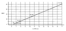
具体的には、実験例1として、ニップ幅を一定値(例えば、7mm)に維持させることを条件として、角度θを変化させた時に必要となる加圧力の値を調査した。また、実験例2として、加圧力を一定値(例えば26kgf/片側)に設定した上で、角度θを変化させたときのニップ幅の変化の状態を調査した。更に、実験例3として、ニップ幅と定着に必要となる設定温度との関係を調査した。
【0054】
実験例1の結果を、図4に示す。また、実験例2の結果を、図5に示す。更に、実験例3の結果を、図6に示す。
【0055】
ここで、図4に示す結果から、垂直加圧(θ=0度)の場合に、7mmのニップ幅を達成するためには、26kgf/片側の加圧力が必要であったものが、傾斜加圧にして角度θを徐々に増すことにより、プラス方向/マイナス方向何れの方向でも、必要となる加圧力が徐々に少なくて済むことになることが判明した。
【0056】
一方、図5に示す結果から、加圧力を例えば26kgf/片側と一定となるように設定した場合において、角度θを0度、即ち、垂直加圧した場合のニップ幅である6.5mmを基準とした場合に、角度θを少しでも設定した場合には(即ち、傾斜加圧とした場合には)、垂直加圧の場合より、プラス方向/マイナス方向何れの方向でも、達成されたニップ幅が徐々に大きくなることが判明した。
【0057】
以上の点から、従来、実施されているような垂直加圧の状態から、本願発明に従って傾斜加圧とすることにより、同一加圧力において、確実に、ニップ幅を増大することが出来ることになる。そして、このようにニップ幅を増大することにより、図6に示す結果から明らかなように、定着に必要となる設定温度を、垂直加圧状態より更に低下させることが可能となり、これにより、省エネルギー化を達成することが出来ることになる。
【0058】
一方、同一ニップ幅を達成する条件でよければ、図4に示す結果から明らかなように、必要となる加圧力を、垂直加圧状態より更に減少させることが可能となり、これにより、装置の小型化が直接的に達成されると共に、加圧力の減少に伴い駆動力に対する負荷が軽減され、これによって省エネルギー化も達成することが出来ることになる。
【0059】
尚、角度θの最適範囲の上限値は、設定された角度θにおいて、定着ローラ12と加圧ローラ16との間で転接状態、即ち、ニップが形成される状態が確保されることが条件となる。この条件に鑑みると、角度θの最適範囲の上限値は、絶対値において80度となる。
【0060】
一方、角度θの最適範囲の下限値は、論理的には、0度を除く値ということになるが、垂直加圧の角度範囲を0度±5度と想定すると、絶対値において5度となる。
【0061】
このように、本願発明の特徴である傾斜加圧を達成する上での角度θの最適範囲は、プラス範囲においては、プラス5度からプラス80度の範囲、また、マイナス範囲においては、マイナス5度からマイナス80度の範囲ということになる。
【0062】
尚、本実施例の角度θは、+48度に設定されており、上述した最適範囲に入るものである。
【0063】
以上詳述したように、この発明によれば、加圧ローラ16の定着ローラ12への付勢軸線(Y)を、定着ローラ12と加圧ローラ16との両中心点を結ぶ軸線(X)を基準とし、付勢軸線(Y)がシートの搬入側に存する場合をプラス、搬出側に存する場合をマイナスとした場合に、軸線Xと軸線Yとのなす角度θを、−5度〜−80度、及び、+5度〜+80度の傾斜加圧の範囲に設定することにより、加圧ローラ16が定着ローラ12に真っ直ぐに転接する垂直加圧の状態と比較して、加圧ローラ16が未定着シートの搬出側または搬入側に寄った(偏倚した)状態で転接することになる。
【0064】
この結果、定着ローラ12と加圧ローラ16との互いの転接部のニップ幅は、同等の加圧力において、垂直加圧の場合と比較してより広く設定されることになる。従って、同等のニップ幅で所望の画像品質及び昇温特性の達成をもくろむ場合には、より低い加圧力で済むこととなり、装置の小型化や駆動機構に要求される出力が低く抑えられえることとり、その効果は絶大である。
【0065】
また、定着ローラが厚肉の弾性体層を有し、尚且つ、角度θがマイナス範囲に存する場合には、転接部における加圧ローラ16の定着ローラ12への圧接状態(圧力分布)を微視的に見ると、この転接部の未定着シートの搬出側の圧力は、搬入側の圧力よりも高められることになる。
【0066】
この結果、角度θを、上記マイナス範囲内に設定することにより、加圧ローラ16の定着ローラ12への圧接方向を、未定着シートの搬出側に偏倚させて転接部における圧力を、搬入側より搬出側を相対的に高く設定させることができ、これにより、この定着ローラ12からの定着済シートの紙剥離性が格段と向上し、分離爪を設けなくても確実に定着ベルト32から分離される効果を更に奏することができることになる。
【0067】
以上詳述したように、この実施例によれば、このように角度θの設定範囲を規定して、傾斜加圧することにより、従来と比較して、より小さい加圧力でも、広いニップ幅を形成することが出来る効果を奏することができる効果を奏することが出来るものである。
【0068】
この発明は、上述した実施例の構成に限定されることなく、この発明の要旨を逸脱しない範囲で種々変形可能である事は言うまでもない。
【0069】
例えば、上述した実施例においては、定着ローラ12の外周面に離型用のオイルを塗布する為のオイル塗布ローラの配設については記載をしなかったが、この発明は、このようなオイル塗布ローラを配設しない構成に限定されることなく、オイル塗布ローラを配設する構成を採用してもよいことは言うまでもない。
【0070】
また、上述した実施例においては、定着ローラ12の芯金24aは、鉄製のパイプから形成されるように説明したが、この発明は、このような構成に限定されることなく、SUS等のステンレススチールやアルミニウム製のパイプから形成されるようにしてもよいことは言うまでもない。
【0071】
また、上述した実施例においては、発熱手段として定着ローラ12に内蔵される加熱源14のみを備えるように説明したが、この発明は、このような構成に限定されることなく、上述した加圧ローラ16に第2の加熱源を内蔵するように構成してもよいものである。この場合、第2の加熱源としては、定着ローラ12に内蔵の加熱源14よりも最大出力が小さく設定された、例えば250Wのハロゲンランプから構成されるようにしてもよい。
【0072】
また、加熱源14としては、上述したようなハロゲンランプのほかに、面状発熱体を利用するものでもよいことは言うまでもない。即ち、その発熱形式、発熱形状に何ら限定されるものでないことはいうまでもない。
【0073】
更に、上述した実施例によれば、定着ローラ12の外周面には、定着動作後ここに付着したシートSを剥離するための剥離爪20が摺接する状態で配設されるように説明したが、この発明は、このような構成に限定されること無く、図7に一変形例として示すように、定着ローラ12の外周面に非接触(摺接しない)状態で配設された剥離ガイド板22から構成されるようにしても良いものである。この場合、剥離ガイド板22の先端は、定着ローラ12の外周面から約0.1mmから1.0mmの範囲で離間するように取付けられている。
【0074】
即ち、この一変形例に示すように、シートSを定着ローラ12の外周面から剥離させるための構成においても、実施例で説明したように、定着ローラ12の外周面に接触する構成であっても良いし、この一変形例において説明したように、非接触な状態で配設されるものであっても良い。
【0075】
これは、搬送されてくるシートSの前端縁部に、未定着トナーがベタ状態で付着している場合は基本的に無く、このため、前端縁部以外の部位に付着した未定着トナーが、転接部を通過する中で加熱加圧作用を受けてシートS上に定着される中で、仮に、定着ローラ12の外周面に付着する事態が発生したとしても、前端縁部は、定着ローラ12の外周面に付着することが無く、この外周面から剥がれているので、この前端縁部が引っ掛かり得る状態で、剥離ガイド板22の先端部を位置するように配設することにより、非接触な状態でも、定着済のシートSの剥離機能を発揮することが出来るものである。
【0076】
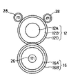
また、上述した第1の実施例によれば、定着ローラ12をハードローラから、加圧ローラ16を弾性ローラから構成するように説明したが、この発明は、このような構成に限定されることなく、図8に第2の実施例として示すように、定着ローラ12及び加圧ローラ16は、共に、同様な弾性を有して構成されても良いものである。
【0077】
詳細には、この第2の実施例においては、定着ローラ12及び加圧ローラ16とも、薄肉の芯金12A,16A´と、この芯金12A,16A´の外周に厚さ1mm〜2mmで配設されたシリコーンゴムからなる薄肉弾性層12B,16B´とから構成されている。そして、この第2の実施例においては、両薄肉弾性層12B、16B´のゴム硬度は、同一に設定されている。
【0078】
一方、定着ローラ12内には、上述した第1の実施例と同様に、加熱源14が収納されていて、内部から加熱して定着ローラ12の外周面を所定の定着温度となるように構成されている。また、加圧ローラ16内にも、定着ローラ12に内蔵された加熱源14と同様の構成の補助加熱源26を収納して、転接部を通過するシートSを、未定着トナーが付着していない面(図中、下面)から加熱するように構成しても良いものである。このように補助加熱源26を備えさせることにより、未定着トナーに加えられる熱量は更に増大し、これにより、シートSの搬送速度を増速させても、転接部を通過する際に定着に必要となる熱量は、シートSに確実に供給されることとなり、このようにして、全体のプロセス速度の上昇を図ることが出来ることになる。
【0079】
また、この定着ローラ12の外周面には、オフセット防止用のオイル塗布ローラ24が転接していて、定着ローラ12の回転に応じて、これの外周面に均一に薄くオフセット防止用のオイルを塗布するように構成されている。
【0080】
この結果、この第2の実施例においては、転接部におけるニップ形状が、略平面状(または、シートSの搬送方向と平行な所謂「平行ニップ」状)になされ、単にオイル塗布ローラ24を介してオフセット防止用のオイルを塗布するだけで、剥離爪22を設けなくても、定着済のシートSを定着ローラ12の外周面に付着させることなく、転接部を無事に通過させることが出来ることになる。
【0081】
また、上述した第2の実施例においては、定着ローラ12の薄肉弾性層12Bと加圧ローラ16の薄肉弾性層16B´とのゴム硬度を同一となるように説明したが、この発明は、このような構成に限定されること無く、例えば、第2の実施例の一変形例として、定着ローラ12の薄肉弾性層12Bのゴム硬度を、加圧ローラ16の薄肉弾性層16B´のゴム硬度より、柔らかく設定して、ニップ形状を、上向きに凸形状となるように設定しても良い。
【0082】
このように第2の実施例の一変形例を構成することにより、上向きに凸形状となされた転接部をシートSが通過することにより、この転接部を通過した時点で、転接部の形状に応じて、下向きに出ようとする癖(腰)がつけられることになる。この結果、オイル塗布ローラ24によりオイルを塗布しなくても、もしくは、このオイルの塗布量を最小限に抑えた状態での塗布でも、剥離爪を用いることなく、シートSを確実に定着ローラ12の外周面から剥離させることが出来ることになる。
【0083】
また、上述した第1の実施例においては、定着ローラ12の外周面を所定の定着温度まで昇温させるために、定着ローラ12内に加熱源14としてのハロゲンランプを収納して、内部から加熱するように説明したが、この発明は、このような構成に限定されること無く、定着ローラ12の外周面を外部から加熱するように構成しても良いものである。
【0084】
以下に、定着ローラ12の外周面を外部から加熱する第3及び第4の実施例の構成を説明する。
【0085】
先ず、図9を参照して、第3の実施例の構成を説明する。この第3の実施例においては、定着ローラ12は、芯金12Aと、この芯金12Aの外周に5mmの厚肉状態で配設されたシリコーンゴムスポンジからなる弾性体層12B´と、この弾性体層12B´の外周を被覆する状態で配設された金属製の薄肉スリーブ12Cとを備えて構成されている。
【0086】
ここで、弾性体層12B´を構成するシリコーンスポンジは、独立気泡を有して形成されている。また、金属製の薄肉スリーブ12Cは、この第3の実施例にいては、図10に取り出して示すように、厚さ35μmのニッケル電鋳製のスリーブ本体12Caと、このスリーブ本体12Caの外周に全面に渡り厚さ200μmで被覆されたシリコーンゴム層12Cbと、このシリコーンゴム層12Cbの外周を全面的に更に被覆する厚さ30μmのPFA樹脂製の離型層12Ccとから構成されている。
【0087】
一方、この第3の実施例においては、加熱源は、定着ローラ12の外周にこれの外周面から離間した状態で近接配置された電磁誘導加熱器26から構成されている。また、この第3の実施例における加圧ローラ16は、詳細は図示していないが、金属製の薄肉状の芯金と、この芯金の外周を被覆する薄肉の合成樹脂層とから構成されている。
【0088】
このように第3の実施例を構成することにより、電磁誘導加熱器26の作用により定着ローラ12の外周に配設された薄肉スリーブ12Cのニッケル電鋳製のスリーブ本体12Caが発熱し、所定の定着温度まで昇温させることが出来ることになる。このように、この第3の実施例によれば、第1及び第2の実施例の場合と同様に、軽荷重で広いニップ幅を達成させることが出来ると共に、広いニップ幅を達成しつつ、装置の小型化、省エネルギー化を達成して、未定着トナーを確実に定着させることが出来ることになる。
【0089】
尚、上述した第3の実施例においては、電磁誘導加熱器26により発熱される対象として金属製のスリーブ12Cを用いるように説明したが、この実施例は、このような構成に限定されること無く、例えば、ポリイミド樹脂等の合成樹脂製のスリーブ内に、電磁誘導で発熱される(即ち、電磁誘導により渦電流が発生して、これにより発熱される)材料を細かく分散させたものも、用いられ得るものであることは言うまでもない。
【0090】
次に、第11図を参照して、定着ローラ12の外周面を外部から加熱する他の実施例としての第4の実施例の構成を説明する。この第4の実施例においては、定着ローラ12は、芯金12Aと、この芯金12Aの外周に厚肉状に配設された厚肉弾性層12B´と、この厚肉弾性層12B´の外周面を被覆するように配設された例えばPFA樹脂製の離型層12Dとを備えて構成されている。
【0091】
一方、この第4の実施例においては、加熱源は、定着ローラ12の外周面に転接する一対の加熱ローラ28から構成されている。ここで、両加熱ローラ28は、定着ローラ12の周方向に沿って離間した状態で配設されている。また、各加熱ローラ28は、詳細は図示していないが、中空状の薄肉芯金と、この薄肉芯金に内蔵されたハロゲンランプとから構成されている。
【0092】
このように第4の実施例を構成することにより、上述した第3の実施例と同様にして、定着ローラ12の外周面を、外部から加熱して、所定の定着加熱温度まで昇温させることが出来、上述した種々の実施例と同様の効果を奏することが出来ることになる。
【0093】
【発明の効果】
以上詳述したように、この発明によれば、軽荷重で広いニップ幅を達成させることの出来る定着装置が提供されることになる。
【0094】
また、この発明によれば、広いニップ幅を達成しつつ、装置の小型化、省エネルギー化を達成することの出来る定着装置が提供されることになる。
【図面の簡単な説明】
【図1】この発明に係わる定着装置の第1の実施例の構成を示す正面断面図である。
【図2】図1に示す定着装置における傾斜加圧の状態を示す図である。
【図3】角度θの定義を説明するための図である。
【図4】ニップ幅を一定値に維持した状態で、角度θと加圧力との相関関係を示す線図である。
【図5】加圧力を一定値に維持した状態で、角度θとニップ幅との相関関係を示す線図である。
【図6】ニップ幅と定着に必要となる設定温度との相関関係を示す線図である。
【図7】図1に示す第1の実施例の構成における剥離爪の変形例を示す正面図である。
【図8】この発明に係わる第2の実施例の構成を示す図である。
【図9】この発明に係わる第3の実施例の構成を示す図である。
【図10】図6に示す金属製の薄肉スリーブを取り出して示す断面図である。
【図11】この発明に係わる第4の実施例の構成を示す図である。
【符号の説明】
10 定着装置
12 定着ローラ
12A 芯金
12B 薄肉弾性層
12B´ 厚肉弾性層
12C 金属製スリーブ
12Ca ニッケル電鋳製のスリーブ本体
12Cb シリコーンゴム層
12Cc 離型層
12D 離型層
14 加熱源(ハロゲンランプ)
16 加圧ローラ
16A 芯金
16A´ 薄肉芯金
16B 本体部
16B´ 薄肉弾性層
18 付勢部材(コイルスプリング)
20 剥離爪
22 剥離ガイド板
24 オイル塗布ローラ
26 発熱源(電磁誘導加熱器)
28 加熱ローラ[0001]
TECHNICAL FIELD OF THE INVENTION
The present invention relates to a fixing device used in a copier, a printer, a facsimile, or the like, for melting and pressing unfixed toner on a sheet and fixing the unfixed toner on the sheet.
[0002]
[Prior art]
In recent years, a fixing device for an electrophotographic apparatus includes a fixing roller having a halogen lamp therein as a heat generating unit, a pressing roller that is in rolling contact with the fixing roller, and fixing the pressing roller with a predetermined pressure. A biasing member for pressing against the roller, wherein the unfixed toner is fixed on the sheet by passing the sheet having the unfixed toner carried on its surface along the rolling contact portion in one direction. A so-called two-roller type fixing device is well known and is in practical use.
[0003]
[Problems to be solved by the invention]
In the two-roller type fixing device having the above-described configuration, when the sheet size is increased as in an A3 size (or A4 transverse feed) compatible machine, the area of the rolling contact portion originally tends to increase, and the fixing property is increased. In order to obtain a wider nip width for improvement, the value of the spring force acting on both ends of the pressure roller must be considerably increased.
[0004]
When the spring force is increased in this manner, the pressing roller itself is warped in the axial direction, and a constant pressing force is not obtained over the entire length in the axial direction. Has been pointed out.
[0005]
When the pressing force between the pressing roller and the fixing roller is increased in this way, the pressing force acts as a load on the rotation of the fixing roller, and as a result, the driving force has to be increased. It has been pointed out that the problem arises that the apparatus cannot be obtained and that the apparatus becomes large and energy consumption increases.
[0006]
As described above, the securing of the pressing force by increasing the spring pressure for increasing the nip width is accompanied by various problems, and there is a strong demand for an improvement that does not involve such problems.
[0007]
The present invention has been made in view of the above circumstances, and a main object of the present invention is to provide a fixing device capable of achieving a wide nip width with a light load.
[0008]
Another object of the present invention is to provide a fixing device capable of achieving a small size and energy saving while achieving a wide nip width.
[0009]
[Means for Solving the Problems]
According to a first aspect of the present invention, there is provided a fixing device that solves the above-described problems and achieves the object, in which a temperature of a fixing roller and an outer peripheral surface of the fixing roller become a predetermined fixing temperature. Heating means, a pressing roller that rolls in contact with the fixing roller, and a biasing member that presses the pressing roller against the fixing roller with a predetermined pressure, and the unfixed toner is carried on the surface. In the fixing device in which the unfixed toner is fixed on the sheet by passing the sheet along the rolling contact portion in one direction, the fixing roller is moved to the surface side of the sheet on which the unfixed toner is carried. And the pressure roller is disposed on the opposite side of the fixing roller with the sheet interposed therebetween, and the urging direction of the urging member is set to the center of the fixing roller and the pressure roller relative to each other. Axis connecting the positions It is characterized in that the set along the direction crossing.
[0010]
Further, according to the fixing device according to the present invention, according to the second aspect, an axis connecting the center point of the fixing roller and the center point of the pressing roller is X, and the pressing roller of the rolling contact portion has Assuming that an axis along the urging direction of the fixing roller is Y, an angle θ between the axis X and the axis Y is + 5 ° <θ <+ 80 ° (however, when the axis X is a reference, , The angle in the case where the axis Y is present on the sheet carry-in side from the axis X is set to be plus.).
[0011]
According to a third aspect of the present invention, there is provided a fixing device, wherein an axis connecting the center point of the fixing roller and the center point of the pressing roller is X, and the axis of the pressing roller in the rolling contact portion is X. Assuming that the axis along the urging direction of the fixing roller is Y, the angle θ between the axis X and the axis Y is −5 ° <θ <−80 ° (however, when the axis X is used as a reference, In this case, the angle is set to be negative when the axis Y is on the sheet unloading side from the axis X.).
[0012]
In the fixing device according to the present invention, the fixing roller is constituted by a hard roller, and the pressure roller is constituted by an elastic roller.
[0013]
According to a fifth aspect of the present invention, the fixing device is a fixed sheet that has passed through the rolling contact portion along the one direction and adheres to an outer peripheral surface of the fixing roller. And a peeling unit for peeling off the sheet from the outer peripheral surface of the fixing roller.
[0014]
According to a sixth aspect of the present invention, in the fixing device, the peeling unit is provided so as to be in contact with an outer peripheral surface of the fixing roller.
[0015]
According to a seventh aspect of the present invention, in the fixing device, the peeling unit is disposed in a non-contact state with the outer peripheral surface of the fixing roller.
[0016]
Further, according to the fixing device according to the present invention, according to
[0017]
In the fixing device according to the present invention, according to the ninth aspect, the heating unit includes a heater built in the fixing roller and configured to heat an outer peripheral surface of the fixing roller from the inside. .
[0018]
According to a tenth aspect of the present invention, in the fixing device, the fixing roller and the pressure roller are both formed of elastic rollers.
[0019]
In the fixing device according to the present invention, the elasticity of the fixing roller and the elasticity of the pressure roller are set to be equal to each other, and the rolling contact portion has a planar shape.
[0020]
According to a twelfth aspect of the fixing device according to the present invention, the elasticity of the fixing roller is set to be relatively softer than the elasticity of the pressure roller.
[0021]
According to a thirteenth aspect of the present invention, the fixing roller and the pressure roller are both made of a metal core and a thin silicone rubber layer disposed around the metal core. And is provided.
[0022]
According to a fourteenth aspect of the present invention, in the fixing device, the heating unit includes a heater built in the fixing roller and configured to heat an outer peripheral surface of the fixing roller from the inside. .
[0023]
In the fixing device according to the present invention, the heating unit is built in the pressure roller, and the unfixed toner adheres to a sheet passing through the rolling contact portion. It is characterized by further comprising an auxiliary heater for heating from a non-existing surface.
[0024]
According to the fixing device of the present invention, the fixing roller is constituted by an elastic roller, and the pressing roller is constituted by a hard roller.
[0025]
According to the fixing device of the present invention, the fixing roller includes a cored bar and a silicone rubber layer disposed in a thick state around the cored bar. It is characterized by being done.
[0026]
In the fixing device according to the present invention, according to
[0027]
In the fixing device according to the present invention, according to claim 19, the heating roller includes a metal sleeve and a heater built in the sleeve. .
[0028]
In the fixing device according to the present invention, according to the twentieth aspect, the heating means is built in the pressure roller, and the unfixed toner adheres to a sheet passing through the rolling contact portion. It is characterized by further comprising an auxiliary heater for heating from a non-existing surface.
[0029]
Further, according to the fixing device of the present invention, according to the twenty-first aspect, the fixing roller includes a core, an elastic layer disposed on the outer periphery of the core, and an outer periphery of the elastic layer. And a thin metal sleeve disposed therein, wherein the pressure roller is a hard roller.
[0030]
According to a twenty-second aspect of the present invention, in the fixing device according to the twenty-second aspect, the heating unit is provided in a non-contact state on an outer periphery of the fixing roller, and the heating unit induces the thin metal sleeve by induction heating. It is characterized by having a heating means.
[0031]
According to a twenty-third aspect of the fixing device according to the present invention, the metal sleeve is made of nickel electroforming.
[0032]
In the fixing device according to the present invention, according to
[0033]
Further, in the fixing device according to the present invention, according to claim 25, the synthetic resin is a polyimide resin.
[0034]
BEST MODE FOR CARRYING OUT THE INVENTION
Hereinafter, the structure of a first embodiment of a fixing device according to the present invention will be described in detail with reference to the accompanying drawings.
[0035]
<< Schematic description of fixing
First, as shown in FIG. 1, a fixing
[0036]
Note that FIG. 1 is a front view, and the details will be described later. However, the unfixed sheet S having unfixed toner carried on the upper surface is moved from right to left in the figure via a transport mechanism (not shown). Is set to be transported.
[0037]
Here, although not shown in detail, the
[0038]
As will be described later in detail, the pressing
[0039]
As a result, in the rolling contact portion (nip portion) of the fixing
[0040]
Further, on the outer peripheral surface of the above-described
[0041]
The leading end of the unfixed sheet conveyed toward the fixing
[0042]
In the fixing
[0043]
Hereinafter, the various components described above will be sequentially described individually.
[0044]
<< Description of fixing
In the first embodiment, the fixing
[0045]
A
[0046]
<< Description of the
The above-described
[0047]
<< Description of the direction of action of the urging force of
In this embodiment, as shown in FIG. 2, an axis connecting the center point A of the fixing
[0048]
As a result, in this embodiment, the
[0049]
In this manner, by biasing the pressing direction of the
[0050]
As a result, by applying a high urging force (spring force) as in the related art, the pressing
[0051]
Further, by increasing the pressing force between the
[0052]
} Verification of optimal range of angle θ}
Next, the optimum range of the angle θ will be verified.
For this verification, for example, as shown in FIG. 3, by changing the urging direction (axis Y) of the urging
[0053]
Specifically, as Experimental Example 1, on the condition that the nip width was maintained at a constant value (for example, 7 mm), the value of the pressing force required when the angle θ was changed was investigated. Further, as Experimental Example 2, the state of the change in the nip width when the angle θ was changed was investigated after setting the pressing force to a constant value (for example, 26 kgf / one side). Further, as Experimental Example 3, the relationship between the nip width and the set temperature required for fixing was investigated.
[0054]
The results of Experimental Example 1 are shown in FIG. FIG. 5 shows the results of Experimental Example 2. FIG. 6 shows the results of Experimental Example 3.
[0055]
Here, from the results shown in FIG. 4, in the case of vertical pressurization (θ = 0 degrees), in order to achieve a nip width of 7 mm, a pressurizing force of 26 kgf / one side was required. It has been found that by gradually increasing the angle θ by applying pressure, the required pressing force is gradually reduced in either the plus direction or the minus direction.
[0056]
On the other hand, from the results shown in FIG. 5, when the pressing force is set to be constant at, for example, 26 kgf / one side, the angle θ is 0 degree, that is, the nip width when vertical pressing is performed is 6.5 mm. When the angle θ is set to a small value (that is, when the pressure is inclined), the nip width achieved in either the plus direction or the minus direction is smaller than that in the case of the vertical pressure. Was found to grow gradually.
[0057]
From the above points, it is possible to reliably increase the nip width at the same pressing force by changing the state of the conventional vertical pressing from the conventional state to the inclined pressing according to the present invention. . By increasing the nip width in this way, as is apparent from the results shown in FIG. 6, it is possible to further reduce the set temperature required for fixing from the state of vertical pressing, thereby saving energy. Can be achieved.
[0058]
On the other hand, if the conditions for achieving the same nip width are acceptable, as is clear from the results shown in FIG. 4, the required pressing force can be further reduced as compared with the vertical pressing state. As a result, the load on the driving force is reduced with a decrease in the pressing force, whereby energy saving can be achieved.
[0059]
The upper limit value of the optimum range of the angle θ is a condition that a state of rolling contact between the fixing
[0060]
On the other hand, the lower limit value of the optimum range of the angle θ is logically a value excluding 0 degree. However, assuming that the angle range of the vertical pressing is 0 degree ± 5 degrees, the absolute value is 5 degrees. Become.
[0061]
As described above, the optimum range of the angle θ for achieving the inclined pressurization, which is a feature of the present invention, is a range from plus 5 degrees to plus 80 degrees in the plus range, and
[0062]
Note that the angle θ in this embodiment is set to +48 degrees, and falls within the above-described optimum range.
[0063]
As described above in detail, according to the present invention, the urging axis (Y) of the
[0064]
As a result, the nip width of the rolling contact portion between the fixing
[0065]
When the fixing roller has a thick elastic layer and the angle θ is in a minus range, the pressure contact state (pressure distribution) of the
[0066]
As a result, by setting the angle θ within the above-mentioned negative range, the pressing direction of the
[0067]
As described in detail above, according to this embodiment, a wide nip width can be formed even with a smaller pressing force as compared with the related art by performing the inclined pressing by defining the setting range of the angle θ as described above. It is possible to obtain the effect that can be obtained.
[0068]
It is needless to say that the present invention is not limited to the configuration of the above-described embodiment, and can be variously modified without departing from the gist of the present invention.
[0069]
For example, in the above-described embodiment, the arrangement of the oil application roller for applying the release oil to the outer peripheral surface of the fixing
[0070]
Further, in the above-described embodiment, the core metal 24a of the fixing
[0071]
Further, in the above-described embodiment, only the
[0072]
Needless to say, the
[0073]
Further, according to the above-described embodiment, the peeling
[0074]
That is, as shown in this modified example, the configuration for separating the sheet S from the outer peripheral surface of the fixing
[0075]
This is basically absent when the unfixed toner adheres in a solid state to the front edge of the conveyed sheet S. Therefore, the unfixed toner adhered to a portion other than the front edge is In the course of fixing on the sheet S under the heating and pressurizing action while passing through the rolling contact portion, even if the fixing
[0076]
Further, according to the first embodiment described above, the fixing
[0077]
More specifically, in the second embodiment, both the fixing
[0078]
On the other hand, similarly to the above-described first embodiment, a
[0079]
An
[0080]
As a result, in the second embodiment, the nip shape at the rolling contact portion is substantially planar (or a so-called “parallel nip” shape parallel to the sheet S transport direction), and the
[0081]
Further, in the above-described second embodiment, the rubber elasticity of the thin
[0082]
By configuring the modified example of the second embodiment in this way, the sheet S passes through the transfer contact portion having an upwardly convex shape, and when the sheet S passes through the transfer contact portion, the transfer contact portion Depending on the shape of the body, a habit (waist) of going downward is provided. As a result, even if the oil is not applied by the
[0083]
In the first embodiment described above, in order to raise the outer peripheral surface of the fixing
[0084]
The configuration of the third and fourth embodiments in which the outer peripheral surface of the fixing
[0085]
First, the configuration of the third embodiment will be described with reference to FIG. In the third embodiment, the fixing
[0086]
Here, the silicone sponge constituting the
[0087]
On the other hand, in the third embodiment, the heating source is constituted by an
[0088]
By configuring the third embodiment in this manner, the nickel electroformed sleeve main body 12Ca of the
[0089]
In the third embodiment described above, the
[0090]
Next, with reference to FIG. 11, a configuration of a fourth embodiment as another embodiment in which the outer peripheral surface of the fixing
[0091]
On the other hand, in the fourth embodiment, the heating source is constituted by a pair of
[0092]
By configuring the fourth embodiment in this manner, the outer peripheral surface of the fixing
[0093]
【The invention's effect】
As described above in detail, according to the present invention, a fixing device capable of achieving a wide nip width with a light load is provided.
[0094]
Further, according to the present invention, there is provided a fixing device capable of achieving a small size and energy saving while achieving a wide nip width.
[Brief description of the drawings]
FIG. 1 is a front sectional view showing the configuration of a first embodiment of a fixing device according to the present invention.
FIG. 2 is a diagram illustrating a state of oblique pressing in the fixing device illustrated in FIG. 1;
FIG. 3 is a diagram for explaining the definition of an angle θ.
FIG. 4 is a diagram showing a correlation between an angle θ and a pressing force while a nip width is maintained at a constant value.
FIG. 5 is a diagram showing a correlation between an angle θ and a nip width in a state where a pressing force is maintained at a constant value.
FIG. 6 is a diagram showing a correlation between a nip width and a set temperature required for fixing.
FIG. 7 is a front view showing a modification of the peeling claw in the configuration of the first embodiment shown in FIG. 1;
FIG. 8 is a diagram showing a configuration of a second embodiment according to the present invention.
FIG. 9 is a diagram showing a configuration of a third embodiment according to the present invention.
FIG. 10 is a cross-sectional view showing the thin metal sleeve shown in FIG. 6;
FIG. 11 is a diagram showing a configuration of a fourth embodiment according to the present invention.
[Explanation of symbols]
10 Fixing device
12 Fixing roller
12A cored bar
12B Thin elastic layer
12B 'Thick elastic layer
12C metal sleeve
Sleeve body made of 12Ca nickel electroformed
12Cb silicone rubber layer
12Cc release layer
12D release layer
14. Heating source (halogen lamp)
16 Pressure roller
16A cored bar
16A 'Thin cored bar
16B body
16B 'Thin elastic layer
18 urging member (coil spring)
20 Peeling nails
22 Peeling guide plate
24 Oil application roller
26 Heat source (electromagnetic induction heater)
28 Heating roller
Claims (25)
前記定着ローラを前記シートの未定着トナーが担持された表面側に配設し、
前記加圧ローラを、間に前記シートを挟んで前記定着ローラの反対側に配設し、
前記付勢部材の付勢方向を、前記定着ローラ及び加圧ローラの互いの中心位置を結ぶ軸線と交差する方向に沿うようにしたことを特徴とする定着装置。A fixing roller, a heating means for heating the outer peripheral surface of the fixing roller to a predetermined fixing temperature, a pressing roller which is in rolling contact with the fixing roller, and fixing the pressing roller with a predetermined pressure. A biasing member for pressing against the roller, wherein the unfixed toner is fixed on the sheet by passing the sheet having the unfixed toner carried on its surface along the rolling contact portion in one direction. In the fixing device,
The fixing roller is disposed on the surface of the sheet on which the unfixed toner is carried,
The pressure roller is disposed on the opposite side of the fixing roller with the sheet therebetween.
The fixing device is characterized in that the urging direction of the urging member is along a direction intersecting an axis connecting the center positions of the fixing roller and the pressure roller.
+5゜<θ<+80゜
(但し、軸線Xを基準とした場合であって、軸線Yが軸線Xからシート搬入側に存在する場合の角度をプラスと設定する。)の関係を満足するように設定されていることを特徴とする請求項1に記載の定着装置。When an axis connecting the center point of the fixing roller and the center point of the pressing roller is X, and an axis along a biasing direction of the pressing roller toward the fixing roller at the rolling contact portion is Y, an axis The angle θ between X and the axis Y is + 5 ° <θ <+ 80 ° (however, when the axis X is the reference and the axis Y is on the sheet carry-in side from the axis X, the angle is set to plus. 2. The fixing device according to claim 1, wherein the fixing device satisfies the following relationship:
−5゜<θ<−80゜
(但し、軸線Xを基準とした場合であって、軸線Yが軸線Xからシート搬出側に存在する場合の角度をマイナスと設定する。)の関係を満足するように設定されていることを特徴とする請求項1に記載の定着装置。When an axis connecting the center point of the fixing roller and the center point of the pressing roller is X, and an axis along a biasing direction of the pressing roller toward the fixing roller at the rolling contact portion is Y, an axis The angle θ formed between X and the axis Y is −5 ° <θ <−80 ° (however, the angle when the axis Y is present on the sheet unloading side from the axis X is minus. 2. The fixing device according to claim 1, wherein the relationship is set to satisfy the following relationship.
前記加熱手段は、前記定着ローラの外周に、非接触状態で配設され、前記薄肉スリーブを誘導加熱させる誘導加熱手段を備えることを特徴とする請求項1乃至3の何れか1項に記載の定着装置。The fixing roller is made of a synthetic resin made of a metal core, an elastic layer disposed on the outer periphery of the core metal, and a material that is disposed on the outer periphery of the elastic layer and that generates heat by electromagnetic induction. With a thin-walled sleeve,
4. The apparatus according to claim 1, wherein the heating unit includes an induction heating unit that is disposed on the outer periphery of the fixing roller in a non-contact state, and induction heats the thin sleeve. 5. Fixing device.
Priority Applications (3)
| Application Number | Priority Date | Filing Date | Title |
|---|---|---|---|
| JP2002312085A JP4390098B2 (en) | 2002-10-28 | 2002-10-28 | Fixing device |
| CNB031045766A CN100409116C (en) | 2002-10-28 | 2003-02-18 | Fixing apparatus |
| US10/691,548 US7239837B2 (en) | 2002-10-28 | 2003-10-24 | Fixing apparatus |
Applications Claiming Priority (1)
| Application Number | Priority Date | Filing Date | Title |
|---|---|---|---|
| JP2002312085A JP4390098B2 (en) | 2002-10-28 | 2002-10-28 | Fixing device |
Publications (2)
| Publication Number | Publication Date |
|---|---|
| JP2004145165A true JP2004145165A (en) | 2004-05-20 |
| JP4390098B2 JP4390098B2 (en) | 2009-12-24 |
Family
ID=32105325
Family Applications (1)
| Application Number | Title | Priority Date | Filing Date |
|---|---|---|---|
| JP2002312085A Expired - Fee Related JP4390098B2 (en) | 2002-10-28 | 2002-10-28 | Fixing device |
Country Status (3)
| Country | Link |
|---|---|
| US (1) | US7239837B2 (en) |
| JP (1) | JP4390098B2 (en) |
| CN (1) | CN100409116C (en) |
Cited By (4)
| Publication number | Priority date | Publication date | Assignee | Title |
|---|---|---|---|---|
| JP2007047365A (en) * | 2005-08-09 | 2007-02-22 | Ricoh Co Ltd | Fixing device and image forming apparatus |
| JP2007212526A (en) * | 2006-02-07 | 2007-08-23 | Ricoh Co Ltd | Fixing device and image forming apparatus |
| US7668494B2 (en) | 2005-11-07 | 2010-02-23 | Sharp Kabushiki Kaisha | Fixing apparatus |
| JP2014134678A (en) * | 2013-01-10 | 2014-07-24 | Canon Inc | Image forming apparatus |
Families Citing this family (4)
| Publication number | Priority date | Publication date | Assignee | Title |
|---|---|---|---|---|
| JP4092329B2 (en) * | 2004-12-17 | 2008-05-28 | 株式会社リコー | Fixing device, separation plate, manufacturing method thereof, and image forming apparatus |
| JP4188385B2 (en) * | 2006-05-12 | 2008-11-26 | シャープ株式会社 | FIXING DEVICE, IMAGE FORMING DEVICE HAVING THE SAME, FIXING DEVICE CONTROL PROGRAM, AND COMPUTER-READABLE RECORDING MEDIUM CONTAINING THE PROGRAM |
| KR101385539B1 (en) * | 2007-03-27 | 2014-04-17 | 삼성전자주식회사 | Fusing device and image forming apparatus having the same |
| JP5233369B2 (en) * | 2008-04-01 | 2013-07-10 | 株式会社リコー | Image forming apparatus |
Family Cites Families (10)
| Publication number | Priority date | Publication date | Assignee | Title |
|---|---|---|---|---|
| JPS575073A (en) * | 1980-06-11 | 1982-01-11 | Toshiba Corp | Fixing device |
| JPH08146800A (en) * | 1994-11-21 | 1996-06-07 | Canon Inc | Fixing device |
| JPH08160791A (en) * | 1994-12-07 | 1996-06-21 | Ricoh Co Ltd | Fixing device |
| JP3896638B2 (en) * | 1997-05-27 | 2007-03-22 | ブラザー工業株式会社 | Fixing device |
| JP3734121B2 (en) * | 1997-08-19 | 2006-01-11 | 株式会社リコー | Belt drive device and belt fixing device |
| KR100386097B1 (en) * | 1999-12-02 | 2003-06-02 | 가부시키가이샤 리코 | Fixing device, fixing method and image forming device by using the same device |
| JP2001343846A (en) * | 2000-06-02 | 2001-12-14 | Matsushita Electric Ind Co Ltd | Fixing unit |
| JP2002110313A (en) * | 2000-10-03 | 2002-04-12 | Canon Inc | Heating device and image forming device |
| JP2002123106A (en) * | 2000-10-19 | 2002-04-26 | Matsushita Electric Ind Co Ltd | Fixing device |
| JP2003057981A (en) * | 2001-08-17 | 2003-02-28 | Nitto Kogyo Co Ltd | Fixing device |
-
2002
- 2002-10-28 JP JP2002312085A patent/JP4390098B2/en not_active Expired - Fee Related
-
2003
- 2003-02-18 CN CNB031045766A patent/CN100409116C/en not_active Expired - Fee Related
- 2003-10-24 US US10/691,548 patent/US7239837B2/en not_active Expired - Fee Related
Cited By (4)
| Publication number | Priority date | Publication date | Assignee | Title |
|---|---|---|---|---|
| JP2007047365A (en) * | 2005-08-09 | 2007-02-22 | Ricoh Co Ltd | Fixing device and image forming apparatus |
| US7668494B2 (en) | 2005-11-07 | 2010-02-23 | Sharp Kabushiki Kaisha | Fixing apparatus |
| JP2007212526A (en) * | 2006-02-07 | 2007-08-23 | Ricoh Co Ltd | Fixing device and image forming apparatus |
| JP2014134678A (en) * | 2013-01-10 | 2014-07-24 | Canon Inc | Image forming apparatus |
Also Published As
| Publication number | Publication date |
|---|---|
| US7239837B2 (en) | 2007-07-03 |
| JP4390098B2 (en) | 2009-12-24 |
| CN100409116C (en) | 2008-08-06 |
| CN1493940A (en) | 2004-05-05 |
| US20040081492A1 (en) | 2004-04-29 |
Similar Documents
| Publication | Publication Date | Title |
|---|---|---|
| JP4655822B2 (en) | Fixing apparatus and image forming apparatus | |
| JP2007065082A (en) | Fixing device and image forming apparatus | |
| JP4609124B2 (en) | Fixing apparatus and image forming apparatus | |
| JP2004226819A (en) | Heating device and image forming apparatus | |
| JP2006243471A (en) | Fixing device and image forming apparatus | |
| JP2005284013A (en) | Fixing device and image forming apparatus | |
| JP2007065092A (en) | Fixing device and image forming apparatus | |
| JP4609116B2 (en) | Fixing apparatus and image forming apparatus | |
| JP2004145165A (en) | Fixing device | |
| JP4821594B2 (en) | Fixing apparatus and image forming apparatus | |
| JP2006235041A (en) | Fixing device and image forming apparatus | |
| JP2008185839A (en) | Fixing device and image forming apparatus | |
| JP2007065068A (en) | Fixing device and image forming apparatus | |
| JP4609114B2 (en) | Fixing device, roll member, and image forming apparatus | |
| JP2006267861A (en) | Image fixing apparatus | |
| JP2004279857A (en) | Heat fixing device and image forming apparatus | |
| JP4164349B2 (en) | Image heating device | |
| JP4770453B2 (en) | Fixing device and image forming apparatus using the same | |
| JP2019158993A (en) | Fixing device | |
| JP2005071637A (en) | Heating device and image forming apparatus | |
| JP2005249992A (en) | Fixing device and image forming apparatus | |
| JP3558939B2 (en) | Belt fixing device and image forming device | |
| JP2004234951A (en) | Heating device | |
| JP2005247484A (en) | Dehumidifier for recording sheet | |
| JPH1173046A (en) | Fixing device |
Legal Events
| Date | Code | Title | Description |
|---|---|---|---|
| A621 | Written request for application examination |
Free format text: JAPANESE INTERMEDIATE CODE: A621 Effective date: 20050817 |
|
| A521 | Written amendment |
Free format text: JAPANESE INTERMEDIATE CODE: A821 Effective date: 20060816 |
|
| RD02 | Notification of acceptance of power of attorney |
Free format text: JAPANESE INTERMEDIATE CODE: A7422 Effective date: 20060816 |
|
| A977 | Report on retrieval |
Free format text: JAPANESE INTERMEDIATE CODE: A971007 Effective date: 20080123 |
|
| A131 | Notification of reasons for refusal |
Free format text: JAPANESE INTERMEDIATE CODE: A131 Effective date: 20080206 |
|
| A521 | Written amendment |
Free format text: JAPANESE INTERMEDIATE CODE: A523 Effective date: 20080403 |
|
| A131 | Notification of reasons for refusal |
Free format text: JAPANESE INTERMEDIATE CODE: A131 Effective date: 20090128 |
|
| A521 | Written amendment |
Free format text: JAPANESE INTERMEDIATE CODE: A523 Effective date: 20090324 |
|
| TRDD | Decision of grant or rejection written | ||
| A01 | Written decision to grant a patent or to grant a registration (utility model) |
Free format text: JAPANESE INTERMEDIATE CODE: A01 Effective date: 20090930 |
|
| A01 | Written decision to grant a patent or to grant a registration (utility model) |
Free format text: JAPANESE INTERMEDIATE CODE: A01 |
|
| A61 | First payment of annual fees (during grant procedure) |
Free format text: JAPANESE INTERMEDIATE CODE: A61 Effective date: 20090930 |
|
| FPAY | Renewal fee payment (event date is renewal date of database) |
Free format text: PAYMENT UNTIL: 20121016 Year of fee payment: 3 |
|
| R150 | Certificate of patent or registration of utility model |
Free format text: JAPANESE INTERMEDIATE CODE: R150 |
|
| LAPS | Cancellation because of no payment of annual fees |