JP2004143809A - Outdoor tent - Google Patents
Outdoor tent Download PDFInfo
- Publication number
- JP2004143809A JP2004143809A JP2002310107A JP2002310107A JP2004143809A JP 2004143809 A JP2004143809 A JP 2004143809A JP 2002310107 A JP2002310107 A JP 2002310107A JP 2002310107 A JP2002310107 A JP 2002310107A JP 2004143809 A JP2004143809 A JP 2004143809A
- Authority
- JP
- Japan
- Prior art keywords
- awning
- tent
- lid
- sheet
- roof
- Prior art date
- Legal status (The legal status is an assumption and is not a legal conclusion. Google has not performed a legal analysis and makes no representation as to the accuracy of the status listed.)
- Granted
Links
Images


Abstract
Description
【0001】
【発明の属する技術分野】上部に天幕屋根を有する外周開放形の野外テントにおいて、突風や強風時に天幕が吹き飛ばされないようにする通風構造に関する。
【0002】
【従来の技術】上部に天幕屋根を有する外周開放形の野外テントでは、テント使用中に突風や強風が吹き込むとテントが吹き飛ばされたり、浮き上がったりすることがあり、時には人に危害を与える虞さえある。したがって、テントに突風や強風が吹き込んだ時の通風構造については、これまでにもいくつかの発明や考案がなされている。そのいずれもが天幕の一部に複数の通風口を設けるとともにその通風口からの雨水の浸入を防ぐための蓋を備えたものであるが、その構造、機能によって2つのタイプが見られる。
【0003】
その1つは、特開平10−37534「テント」や特開平6−66053「風孔を設けたテント」、あるいは実用新案登録第3019737号「含み風の逃がし口を設けたシート及びテント」に見られるように、風圧によって前記蓋を持ち上げるもので、常時は蓋の重さで天幕に接合している構造のものである。
しかしこのタイプのテントは、天幕を折り畳んで収納する際、蓋の端縁一部めくり上がって天幕から離れ、折り畳み作業がしにくくなる場合がある。したがって前記発明の一部には蓋の下端を紐によって天幕に係止したものも見られるが、紐の長さによっては蓋の開口が制限される難点がある。
【0004】
もう1つは、特開平6−45002「テント」に見られるように、晴天時には蓋を開放しておき、雨天時には蓋を閉じて使用するタイプのものである。蓋の解放時、及び閉鎖時に蓋を天幕に係止する機構が備わっているので、天幕の収納時に蓋が天幕から離れて作業がしにくくなるという虞はないが、雨天使用時に突風又は強風が吹き込むと、風抜き機構としての通風口の役割が果たせないという問題点がある。
【0005】
【発明が解決しようとしている課題】上記従来の技術に鑑み、常時は天幕に設けた通風口が、その外面部を覆う蓋と天幕とが面ファスナー等で中程度の固定力で係止されて塞がれ、突風又は強風がテント内に吹き込んだときその風圧によってこの係止が自動的に解除され通風口が開き、突風又は強風でも天幕が吹き飛ばされない野外テントを提供する。
【0006】
【課題を解決するための手段】本発明者は、次の手段により上記課題を解決した。
(1)上部に天幕屋根を有する外周開放形の野外テントにおいて、天頂部付近の天幕屋根に1つの穴からなる通風口又は複数の穴を隣接配置されてなる通風口を1又は複数個配設し、かつ前記通風口ごとその外面部に、1枚のシート状の蓋を、その上端縁をテントの天頂部の梁に掛かる部分で天幕に逢着、糊着け等して固着し、同蓋の他の端縁は複数の面ファスナーの小片等よりなる中程度の固定力を発現する係止手段により通風口に隣接する天幕端縁部に係止してなり、突風又は強風を受けると前記蓋が自動的に開口し、天幕が吹き飛ばされないようになしたことを特徴とする野外テント。
(2)隣接配置された穴と穴の間に残された天幕屋根の部分が、天幕屋根の強度を保持し得る形状、本数及び幅を持ち、かつ前記1又は複数の穴で構成される通風口の総面積が、突風又は強風を受けたときに前記蓋が開口し得る大きさを有することを特徴とする前記(1)に記載の野外テント。
(3)シート状の蓋が、防水処理されてなるものであることを特徴とする前記(1)又は(2)に記載の野外テント。
【0007】
(4)シート状の蓋の左右端縁部が、通風口の左右端縁に折りひだによって伸縮自在に構成された防水シートを介して固着され、前記蓋の開口時に通風口の左右端からのテント内への雨水の流入を防止できるようになしたことを特徴とする前記(1)〜(3)のいずれか1項に記載の野外テント。
(5)上部に天幕屋根を有する外周開放形の野外テントにおいて、天幕の左右の垂直壁状側面に、複数の直角三角形状の通風口を設け、かつ同通風口の外面部に、ほぼ同形状のシート状の蓋を、
その斜辺端縁を直角三角形状通風口の天幕端縁部に固着し、同蓋の他の端縁は複数の面ファスナー小片等よりなる中程度の固定力を発現する係止手段により通風口に隣接する天幕端縁部に係止されてなり、突風又は強風を受けると前記蓋が自動的に開口し、天幕が吹き飛ばされないようになしたことを特徴とする前記(1)〜(4)のいずれか1項に記載の野外テント。
【0008】
(6)上部に天幕屋根を有する外周開放形の野外テントにおいて、天幕の垂直壁状側面が、直角三角形状の2枚のシートをその垂直辺が互いに接するようにして対称形に配置して構成され、かつそれぞれのシートの斜辺端縁が天幕屋根に固着され、またいずれか一方のシートの垂直辺端縁から1又は複数のシート片を突出し、該シート片が1又は複数の面ファスナー小片等よりなる中程度の固定力を発現する係止手段により他方のシートの垂直辺端縁に係止されてなり、突風又は強風を受けると前記突出部が自動的に剥離して天幕が吹き飛ばされないようになしたことを特徴とする野外テント。
【0009】
(7)上部に天幕屋根を有する外周開放形の野外テントにおいて、天幕の垂直壁状側面が、直角三角形状の2枚のシートをその垂直辺が互いに接するようにして対称形に配置して構成され、かつそれぞれのシートの斜辺端縁が天幕屋根に固着され、またいずれか一方のシートの垂直辺端縁から1又は複数のシート片を突出し、該シート片が1又は複数の面ファスナー小片等よりなる中程度の固定力を発現する係止手段により他方のシートの垂直辺端縁に係止されてなり、突風又は強風を受けると前記突出部が自動的に剥離して天幕が吹き飛ばされないようになしたことを特徴とする前記(1)〜(4)のいずれか1項に記載の野外テント。
【0010】
(8)シート状の蓋が、天幕と同様の帆布製のものであることを特徴とする前記(1)〜(5)、(7)のいずれか1項に記載の野外テント。
(9)蓋の係止手段が、通風口に隣接する天幕端縁部に一部をフリーに残して係止されてなるものであることを特徴とする前記(1)〜(5)及び(7)〜(8)のいずれか1項に記載の野外テント。
(10)天幕屋根に設けた蓋が、その下部両端をゴムひもを介して係止されてなることを特徴とする前記(1)〜(5)及び(7)〜(9)のいずれか1項に記載の野外テント。
(11)天幕屋根に設けた蓋が、その下部両端又は通風口の下部両隅付近の天幕に固着された紐、金属、プラスチック等のリングに挿通され、通風口の下部両端付近の天幕又は前記蓋の下部両端部の2点にその両端が固着されたゴムひもを介して係止されてなることを特徴とする前記(1)〜(5)及び(7)〜(10)のいずれか1項に記載の野外テント。
【0011】
【発明の実施の形態】本発明の実施の形態を実施例の図によって説明する。
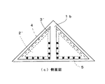
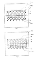
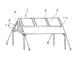
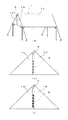
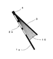
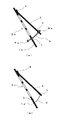
図1は本発明の一実施例の斜視図(a)と上面一部断面図(b)、図2は図1に示す実施例の側面図(c)、図3は本発明の他の実施例の斜視図(a)と平面図(b)、図4は本発明の第3の実施例の上面一部断面図、図5は本発明の第4の実施例の斜視図、図6は本発明の第5の実施例の斜視図(a)及び側面図(b)、(c)、図7は本発明の第6の実施例の斜視図である。
また、図8は蓋の左右端縁が折りひだによって伸縮自在に構成されたプリーツ状の防水シートを介して天幕に固着された状態を示す図であり、図9は天幕と蓋の係止の実施例の構造断面図である。
図において1は天幕、1aは天幕の屋根、1bは天幕の垂直壁状側面、1b’、1b”は垂直壁状側面を構成する三角形状シート、2、2’は通風口、2aは通風口を構成する穴(2a1:長方形の穴、2a2:三角形または菱形の穴、2a3:円形の穴)、3、3’は蓋、4は天幕と通風口蓋の固着部、5は面ファスナー小片、6は突出シート片、7は鳩目、8は紐又は棒状体、8aはストッパー、9はゴムひも、10はプリーツ状の防水シートを示す。
【0012】
(実施例1)
図1(a)に示す実施例では、天幕1の屋根1aの天頂部付近に、図1(b)に示す複数の長方形状の穴2a1を碁盤目状に隣接して配置した通風口2と、該通風口2の外面部を覆う長方形状の1枚のシート状の蓋3が設けられ、また、天幕の左右の垂直壁状側面の4箇所に直角三角形状の通風口2’とそれぞれの通風口2’の外面部を覆う直角三角形のシート状の蓋3’が設けられている。
天幕の屋根1aの天頂部付近の複数の長方形の穴2a1からなる通風口2を覆う長方形状の蓋3は、図1(b)に示すように、その上端縁がテントの天頂部の梁に掛かる部分で天幕に逢着、糊付け等で固着されており(固着部4)、また他の3つの端縁は、天幕1aと蓋3との相重なる部分の複数箇所に固着された面ファスナーの小片5によって中程度の固定力によって天幕屋根に係止されている。
上下、左右に隣接する複数の穴2a1の間に残された格子状の天幕屋根の部分の幅及び本数は、天幕の強度を維持できる程度でよく、通風口の通風面積を可能な限り大きくとることが望ましい。また長方形の穴2a1がすべて同一形状である必要はなく、テント内に突風又は強風が吹き込んだ際に前記面ファスナー小片5の係止を早期に解除できるよう、天幕屋根1aに配設する穴2aの面積を上方より下方の方を大きくするなど通風効果を高める形状を採ることも好ましい。
なお、ここで中程度の固定力というのは、テント内に吹き込む突風又は強風によって前記面ファスナー小片5による固定が解除される程度の固定力をいう(以下同様)。
また、天幕の側面1bの直角三角形状の蓋3’は、図2に示すように、その直角三角形状の斜辺にあたる端縁が直角三角形状通風口2’の斜辺周辺の天幕側面1bに縫着、糊着け等の手段によって固着され、他の2辺の端縁は天幕側面1bと相重なる部分の複数箇所にそれぞれ固着された面ファスナーの小片5によって中程度の固定力で係止されている。
【0013】
(実施例2)
図3(a)に示す実施例では、天幕1の屋根1aの天頂部付近に、図3(b)に点線で示す1つの長方形状の穴で通風口2が形成され、該通風口2の外面部を覆う長方形状の1枚のシート状の蓋3が設けられ、また天幕の左右の垂直壁状側面の4箇所に直角三角形状の通風口2’とそれぞれの通風口2’の外面部を覆う直角三角形のシート状の蓋3’が設けられている。
天幕の屋根1aの天頂部付近の1つの長方形の穴からなる通風口2を覆う長方形状の蓋3は、図3(b)に示すように、その上端縁がテントの天頂部付近の天幕に逢着、糊付け等で固着されており(固着部4)、また他の3つの端縁は、天幕1aと蓋3との相重なる部分の複数箇所に固着された面ファスナーの小片5によって中程度の固定力によって天幕屋根に係止されている。
【0014】
(実施例3)
図4(a)に示す実施例は、実施例1に示した構成の天幕において、天幕1の屋根1aの天頂部付近に配設され通風口2を形成する複数の穴2aの形状を実施例1で示した長方形の穴2a1と形状を異にしたものである。
本実施例では、天幕1の屋根1aの天頂部付近に、複数の三角形及び菱形の穴2a2を上下左右に隣接して配設して通風口2を構成し、該通風口2の外面部に前記穴2a2のすべてを覆う長方形の1枚のシート状の蓋3が設けられ、前記蓋3は、その上端縁がテントの天頂部の梁に掛かる部分で天幕屋根1aに逢着、糊付け等で固着されており(固着部4)、また他の3つの端縁は、天幕屋根1aと蓋3との相重なる部分の複数箇所に固着された面ファスナーの小片5によって中程度の固定力によって天幕屋根1aに係止されている。
互いに隣接する複数の穴2a2の間に残された天幕屋根1aの斜め格子状の部分の幅及び本数は、天幕1の強度を維持できる程度でよく、通風口2の面積を可能な限り大きくとることが望ましい。また三角形及び菱形の穴2a2がすべて同一面積である必要はなく、突風又は強風が吹き込んだ際に面ファスナー小片5の係止が迅速に解除できるよう、天幕屋根1aに配設する穴2a2の面積を上方より下方の方を大きくするなど、通風効果を高める形状、寸法を採るのも好ましい。
なお、前記穴2aの形状は、実施例1に示した長方形の穴2a1、及び図4(a)に示した三角形または菱形の穴2a2に限られるものではなく、図4(b)に示す円形の穴2a3のほか、楕円形、多角形など天幕1の形状が維持でき、かつ通風口2の面積が可能な限り大きくなる形状であればよい。またこの場合もすべての穴が同一面積である必要もない。
【0015】
(実施例4)
図5に示す実施例では、天頂部付近の天幕屋根1aに1又は複数の穴2a(図示せず)を隣接配置した通風口2を複数個配設し、かつそれぞれの通風口2にそれぞれ1枚のシート状の蓋3が設けられ、また天幕の左右の垂直壁状側面の4箇所に直角三角形状の通風口2’とそれぞれの通風口2’の外面部を覆う直角三角形状のシート状の蓋3’が設けられている。
前記複数の通風口2はすべて同一形状、同一面積である必要はなく、又天幕の屋根1aと蓋3の面ファスナー5等による固定力も同一である必要はなく、突風又は強風がテント内に吹き込んだとき、その風圧の大小によって蓋3が自動的かつ効果的に開口する形態であればよい。
なお天幕の屋根1aの通風口2周辺の構造及び垂直壁状側面1bの通風口2’付近の構造は、実施例1〜3に示すのと同様であるので詳細は省略する。
【0016】
(実施例5)
図6(a)の実施例は、図6(b)に示すように、天幕左右の垂直壁状側面1bが直角三角形状の2枚のシート1b’、1b”をその垂直辺が互いに接するようにして対称形に配置して構成され、かつそれぞれのシート1b’、1b”の斜辺端縁が天幕屋根1aに固着され、また一方のシート1b’の垂直辺端縁から1枚のシート片6を突出し、該シート片6が複数の面ファスナー小片5により他方のシート1b”の垂直辺端縁に中程度の固定力で係止されており、突風又は強風を受けると天幕側面が開放されて通風口となり天幕が吹き飛ばされるのを防止する。
なお、図6(b)では、垂直壁状側面1bを構成する2枚の直角三角形状シートの一方1b’を、その垂直辺端縁から1枚のシート片6を突出させ、そのシート片6を複数の面ファスナーの小片5により他の直角三角形状のシート1b”に係止しているが、図6(c)に示すように、直角三角形状のシート1b’の垂直辺端縁から複数のシート片6を突出させ、その複数のシート片6それぞれを1個の面ファスナー5により他方の直角三角形状のシート1b”の垂直辺端縁に係止するものであってもよい。
【0017】
(実施例6)
図7の実施例は、天幕1の屋根1aの天頂部付近に、複数の穴2aを隣接して配設してなる実施例1又は2で説明した通風口2と、該通風口2の外面部を覆う長方形の1枚のシート状蓋3とを設け、さらに天幕の左右の垂直壁状側面1bを実施例5で示した直角三角形状の2枚のシート1b’、1b”によって構成したものである。本実施例における天幕1の屋根1aと前記長方形状の蓋3との係止方法、及び垂直壁状側面の2枚のシート1b’と1b”との係止方法は、実施例1、2及び3で説明したのと同様であるので詳細は省略する。
【0018】
上記の実施例1、2、3、5、における通風口2と通風口2を覆う蓋3との面積比は、雨天時に突風又は強風によって前記蓋3が吹き上げられた場合の雨水の流入具合を考慮して定められるが、図8に示すように、シート状の蓋の左右端縁部を、折りひだによって伸縮自在に構成されたプリーツ状の防水シート10を介して天幕の屋根1aに固着し、前記蓋3の開口時に通風口2の左右端から雨水の流入を効果的に防止する手段を採ることも好ましい。
【0019】
前記天幕1の屋根1aと前記長方形状の蓋3、天幕1の垂直壁状側面1bと直角三角形状の蓋3’、及び天幕1の垂直壁状側面を構成する2枚の直角三角形状のシート1b’と1b”との係止手段が、面ファスナーのほか、磁石の吸着力によるものであってもよい。また、図9(a)に示すように天幕1と蓋3の相対する位置に設けた鳩目7に挿通し、両端にストッパー8aを備え、かつ鳩目7との間の摩擦力の小さい、例えばビニール紐やプラスチックス製の棒状体8を、突風又は強風によって前記蓋3が通風口2から風圧を逃すのに必要な高さまで吹き上がる長さを持たせて取り付けたものであってもよい。
【0020】
突風又は強風によって浮き上がった蓋3が、めくれ上がったまま通風口2が閉じない状況になるのを防止するため、図9(b)に示すように前記蓋3の下部両端をゴムひも9を介して天幕に係止したり、その下部両端又は通風口の下部両隅付近の天幕に固着された紐、金属、プラスチックス等のリングに挿通され、通風口の下部両隅付近の天幕又は前記蓋の下部両端部の2点にその両端が固着されたゴムひも9を介して係止したりするのも有効である。
【0021】
【発明の効果】本発明によって次のような効果が発揮される。
▲1▼ テント内に突風や強風が吹き込んだとき、天幕屋根の天頂付近に隣接配設した1又は複数の穴からなる通風口、及び垂直壁状側面に設けた通風口の外面部を覆う蓋が自動的に開口することにより、突風又は強風によるテントの倒壊や浮き上がりが防止でき、これに伴う人への危害の虞が減少する。
▲2▼ 天幕の垂直壁状側面が2枚のシートで構成され、かつ両シートの相接する垂直辺が、一方のシートから突出したシート片に面ファスナー等中程度の固定力を発現する係止手段で係止されていることにより、テント内に突風又は強風が吹き込んだとき垂直壁面状側面が開放され、突風又は強風によるテントの倒壊や浮き上がりが防止でき、これに伴う人への危害の虞が減少する。
▲3▼ 天幕と通風口蓋が面ファスナー等で緩やかに係止されており、突風又は強風による風圧でこの面ファスナー等による係止が解除され、風圧が消滅すると通風口の蓋が自重又は蓋の下部両端に備えたゴムひもの弾性によって元に戻り、面ファスナー等により天幕と通風口を覆う蓋とが再度係止されるので、雨天時の突風又は強風にも対応できる。
▲4▼ 通風口の蓋の左右端縁が、折りひだによって伸縮自在に構成されてなる防水シートを介して天幕に固着されているので、通風口開口時に通風口左右端からの雨水の流入が防止できる。
▲5▼ 天幕と通風口を覆う蓋が面ファスナー等で係止されているので、テント使用後の折り畳み収納作業が円滑に行える。
▲6▼ 複数の穴と穴の間に残された天幕部分の張力が、天幕の形状を維持するので、通風口付近の天幕が垂れ下がるなどといった不都合が生ぜず、かつ通風口外面部に設けた蓋の天幕内への陥入も防止できる。
▲7▼ 従来の野外テントの天幕のみの改造によって、本発明の野外テントが容易に実現できる。
【図面の簡単な説明】
【図1】本発明の一実施例の斜視図(a)と上面一部断面図(b)、
【図2】図1に示す実施例の側面図(c)、
【図3】本発明の他の実施例の斜視図(a)と平面図(b)、
【図4】本発明の第3の実施例の上面一部断面図(a)(b)、
【図5】本発明の第4の実施例の斜視図、
【図6】本発明の第5の実施例の斜視図(a)及び側面図(b)(c)、
【図7】本発明の第6の実施例の斜視図、
【図8】蓋の左右端縁が折りひだによって伸縮自在に構成されたプリーツ状の防水シートを介して天幕に固着された状態を示す図、
【図9】天幕と蓋の係止の実施例の構造断面図(a)(b)、
【符号の説明】
1:天幕 1a:天幕の屋根
1b:天幕の垂直壁状側面
1b’、1b”:垂直壁状側面を構成する三角形状シート
2、2’:通風口 2a:天幕屋根の通風口を構成する穴
2a1:長方形の穴 2a2:三角形または菱形の穴
2a3:円形の穴 3、3’:蓋
4:天幕と通風口蓋の固着部 5:面ファスナー小片
6:突出シート片 7:鳩目
8:紐又は棒状体 8a:ストッパー
9:ゴムひも 10:プリーツ状の防水シート[0001]
BACKGROUND OF THE
[0002]
2. Description of the Related Art In an open-ended outdoor tent having a tent roof at the top, if a gust or strong wind blows during use of the tent, the tent may be blown off or lifted up, sometimes causing harm to humans. is there. Therefore, several inventions and ideas have been made on the ventilation structure when a gust or strong wind blows into the tent. Each of them has a plurality of ventilation holes provided in a part of the awning and a lid for preventing rainwater from entering through the ventilation holes, but two types are seen depending on the structure and function.
[0003]
One of them is found in JP-A-10-37534 "tent" and JP-A-6-66053 "tent with air vent" or Utility Model Registration No. 3019737 "sheets and tents with vents for escape wind". As described above, the lid is lifted by wind pressure, and is always connected to the awning by the weight of the lid.
However, in this type of tent, when the awning is folded and stored, the edge of the lid may be partially turned up and separated from the awning, making it difficult to fold the tent. Therefore, in some of the inventions, the lower end of the lid is locked to the awning by a cord, but there is a drawback that the opening of the lid is restricted depending on the length of the cord.
[0004]
The other is a type in which the lid is opened when the weather is fine and the lid is closed when it is rainy, as seen in Japanese Patent Application Laid-Open No. 6-45002 "tent". There is a mechanism to lock the lid to the awning when the lid is opened and closed, so there is no danger that the lid will be separated from the awning when the awning is stored, making it difficult to work, but gusts or strong winds when using in rainy weather When blown, there is a problem that the role of a ventilation port as a ventilation mechanism cannot be fulfilled.
[0005]
SUMMARY OF THE INVENTION In view of the above-mentioned conventional technology, the ventilation opening provided in the awning is always fixed to the lid covering the outer surface of the awning and the awning with a hook-and-loop fastener or the like with a moderate fixing force. When the tent is closed and a gust or strong wind blows into the tent, the lock is automatically released by the wind pressure, the ventilation opening is opened, and the tent is not blown off even by the gust or strong wind.
[0006]
The present inventor has solved the above problem by the following means.
(1) In an open-ended outdoor tent having a tent roof at the top, one or a plurality of vents with one hole or a plurality of holes are arranged on the tent roof near the zenith. And a sheet-like lid is fixed to the outer surface of the tent together with the ventilation opening at the portion where the upper edge of the lid is hung on the beam at the zenith of the tent, glued or the like, and fixed. The other edge is locked to the edge of the awning adjacent to the ventilation opening by a locking means that develops a moderate fixing force composed of a plurality of small pieces of hook-and-loop fasteners, and the lid is closed when a gust or strong wind is received. An open-air tent that automatically opens to prevent the tent from being blown away.
(2) The portion of the tent roof left between the holes arranged adjacent to each other has a shape, number and width capable of maintaining the strength of the tent roof, and is composed of the one or more holes. The outdoor tent according to (1), wherein the total area of the mouth has a size such that the lid can be opened when receiving a gust or strong wind.
(3) The outdoor tent according to (1) or (2), wherein the sheet-like lid is subjected to a waterproof treatment.
[0007]
(4) The left and right edges of the sheet-shaped lid are fixed to the left and right edges of the ventilation port via a waterproof sheet that is configured to be stretchable by folding and folded, and when the lid is opened, the left and right edges of the ventilation port are connected. The outdoor tent according to any one of (1) to (3), wherein rainwater can be prevented from flowing into the tent.
(5) In an open-ended outdoor tent having a tent roof at the top, a plurality of right-angled triangular ventilation holes are provided on the left and right vertical wall-like side surfaces of the awning, and the outer surfaces of the ventilation holes have substantially the same shape. The sheet-like lid of
The edge of the oblique side is fixed to the edge of the awning of the right-angled triangular ventilation port, and the other edge of the lid is attached to the ventilation port by a locking means that expresses a moderate fixing force consisting of a plurality of hook-and-loop fasteners. (1) to (4), wherein the lid is automatically opened when a gust or strong wind is received so as to prevent the awning from being blown off. An outdoor tent according to any one of the preceding claims.
[0008]
(6) In an open-ended outdoor tent having an awning roof at the top, a vertical wall-like side surface of the awning is formed by symmetrically arranging two right triangular sheets so that their vertical sides are in contact with each other. And the oblique edge of each sheet is fixed to the awning roof, and one or more sheet pieces protrude from the vertical edge of one of the sheets, and the sheet piece is one or more surface fastener small pieces or the like. It is locked to the vertical side edge of the other sheet by a locking means that expresses a moderate fixing force, so that when a gust or strong wind is received, the protruding portion is automatically peeled off and the awning is not blown off An outdoor tent characterized by the following:
[0009]
(7) In an open-ended outdoor tent having an awning roof at the top, a vertical wall-like side surface of the awning is configured by symmetrically arranging two right-angled triangular sheets such that their vertical sides contact each other. And the oblique edge of each sheet is fixed to the awning roof, and one or more sheet pieces protrude from the vertical edge of one of the sheets, and the sheet piece is one or more surface fastener small pieces or the like. It is locked to the vertical side edge of the other sheet by a locking means that expresses a moderate fixing force, so that when a gust or strong wind is received, the protruding portion is automatically peeled off and the awning is not blown off The outdoor tent according to any one of the above (1) to (4), wherein:
[0010]
(8) The outdoor tent according to any one of (1) to (5) and (7), wherein the sheet-like lid is made of canvas similar to the awning.
(9) The above-mentioned (1) to (5) and (5), wherein the locking means of the lid is locked while leaving a part free at the edge of the awning adjacent to the ventilation opening. The outdoor tent according to any one of 7) to (8).
(10) Any one of the above (1) to (5) and (7) to (9), wherein a lid provided on the awning roof is locked at both lower ends thereof via rubber cords. Outdoor tent according to the paragraph.
(11) The lid provided on the awning roof is inserted through a ring of metal, plastic, or the like fixed to the lower end of the awning or the awning near the lower both corners of the ventilation opening, and the awning near the lower both ends of the ventilation opening or the aforementioned Any one of the above (1) to (5) and (7) to (10), wherein two ends of the lower end of the lid are locked via rubber cords whose both ends are fixed. Outdoor tent according to the paragraph.
[0011]
DESCRIPTION OF THE PREFERRED EMBODIMENTS Embodiments of the present invention will be described with reference to the drawings.
FIG. 1 is a perspective view (a) of one embodiment of the present invention and a partial cross-sectional view of the upper surface (b), FIG. 2 is a side view (c) of the embodiment shown in FIG. 1, and FIG. FIG. 4 is a perspective view of a third embodiment of the present invention, FIG. 5 is a perspective view of a fourth embodiment of the present invention, and FIG. A perspective view (a) and side views (b), (c), and FIG. 7 of a fifth embodiment of the present invention are perspective views of a sixth embodiment of the present invention.
FIG. 8 is a diagram showing a state in which the left and right edges of the lid are fixed to the awning via a pleated waterproof sheet formed to be stretchable by folding, and FIG. 9 is a diagram showing the locking of the awning and the lid. It is a structure sectional view of an example.
In the figure, 1 is an awning, 1a is a roof of the awning, 1b is a vertical wall-like side surface of the awning, 1b ', 1b "is a triangular sheet constituting the vertical wall-like side surface, 2, 2' is a ventilation opening, and 2a is a ventilation opening. (2a 1 : rectangular hole, 2a 2 : triangular or rhombic hole, 2a 3 : circular hole), 3 ′ is a lid, 4 is a fixing portion between the awning and the ventilating lid, 5 is a hook-and-loop fastener A small piece, 6 is a protruding sheet piece, 7 is an eyelet, 8 is a string or a rod, 8a is a stopper, 9 is an elastic cord, and 10 is a pleated waterproof sheet.
[0012]
(Example 1)
Figure 1 In the example shown in (a), in the vicinity of the top portion of the
As shown in FIG. 1 (b), the
Vertically, the width and the number of parts of the lattice-shaped tent roof left between the plurality of holes 2a 1 adjacent to the left and right may be a enough to maintain the strength of the tent, as far as possible the ventilation area of the ventilation openings larger It is desirable to take. The holes 2a 1 of the rectangle all need not be the same shape, so that it can release the engagement of said
Here, the medium fixing force means a fixing force at which the fixing by the hook-and-loop fastener
As shown in FIG. 2, the right-angled triangular lid 3 'on the side surface 1b of the awning is sewn to the awning side 1b around the hypotenuse of the right-angled triangular ventilation opening 2' as shown in FIG. The other two edges are locked with medium fixing force by small pieces of hook-and-
[0013]
(Example 2)
In the embodiment shown in FIG. 3A, a
As shown in FIG. 3 (b), the
[0014]
(Example 3)
In the embodiment shown in FIG. 4A, in the awning having the configuration shown in the first embodiment, the shape of the plurality of holes 2 a that are arranged near the zenith of the roof 1 a of the
In this embodiment, in the vicinity of the top portion of the
The width and the number of oblique lattice portions of the awning roof 1a left between the plurality of holes 2a 2 adjacent to each other may be such that the strength of the
The shape of the hole 2a is not limited to the rectangular hole 2a 1 shown in the first embodiment and the triangular or rhombic hole 2a 2 shown in FIG. 4 (a). in addition to the circular hole 2a 3 showing, elliptical, polygonal, etc. to maintain the shape of the
[0015]
(Example 4)
In the embodiment shown in FIG. 5, a plurality of
It is not necessary that all of the plurality of
The structure around the
[0016]
(Example 5)
In the embodiment of FIG. 6 (a), as shown in FIG. 6 (b), the left and right vertical side walls 1b of the awning form two sheets 1b ′ and 1b ″ each having a right-angled triangle so that their vertical sides are in contact with each other. Symmetrically arranged, and the oblique edges of the respective sheets 1b 'and 1b "are fixed to the awning roof 1a, and one sheet piece 6 extends from the vertical edge of one of the sheets 1b'. The sheet piece 6 is fixed to the vertical side edge of the other sheet 1b ″ by a plurality of hook-and-
In FIG. 6B, one of the two right-angled triangular sheets 1b 'constituting the vertical wall-shaped side surface 1b is made to project from the vertical side edge by one sheet piece 6, and the sheet piece 6 Is locked to another right-angled triangular sheet 1b ″ by a plurality of
[0017]
(Example 6)
The embodiment shown in FIG. 7 has the
[0018]
The area ratio between the
[0019]
The roof 1 a of the
[0020]
As shown in FIG. 9 (b), the lower ends of the
[0021]
According to the present invention, the following effects are exhibited.
(1) When a gust or strong wind blows into the tent, a lid that covers one or more holes adjacent to the zenith of the tent roof and the outer surface of the ventilation hole provided on the vertical wall side Automatically opening the tent, it is possible to prevent the tent from collapsing or rising due to gusts or strong winds, and to reduce the risk of harm to humans due to this.
{Circle around (2)} The vertical wall-like side surface of the awning is composed of two sheets, and the adjacent vertical sides of both sheets express a moderate fixing force such as a hook-and-loop fastener to a sheet piece protruding from one sheet. By being locked by the stopping means, when a gust or strong wind blows into the tent, the vertical wall-like side surface is opened, and the tent can be prevented from collapsing or rising due to gust or strong wind, resulting in harm to people. Risk is reduced.
(3) The awning and the vent cover are gently locked by hook-and-loop fasteners, etc., and the lock by the hook-and-loop fastener is released by wind pressure due to gusts or strong winds. It returns to its original state due to the elasticity of the elastics provided at the lower ends, and the tent and the lid covering the ventilation opening are locked again by a hook-and-loop fastener or the like, so that it is possible to cope with a gust or strong wind in rainy weather.
(4) Since the left and right edges of the ventilation opening lid are fixed to the awning via a waterproof sheet that is made to be stretchable by folding, the inflow of rainwater from the left and right ends of the ventilation opening when the ventilation opening is opened. Can be prevented.
(5) Since the lid that covers the tent and the ventilation opening is locked with hook-and-loop fasteners, the folding and storage work after using the tent can be performed smoothly.
(6) Since the tension of the awning portion left between the holes maintains the shape of the awning, there is no inconvenience such as the awning near the ventilation opening hanging down, and it is provided on the outer surface of the ventilation opening. It is also possible to prevent the lid from entering the tent.
{Circle around (7)} The outdoor tent of the present invention can be easily realized by modifying only the tent of the conventional outdoor tent.
[Brief description of the drawings]
FIG. 1 is a perspective view (a) and a partial top sectional view (b) of an embodiment of the present invention;
FIG. 2 is a side view (c) of the embodiment shown in FIG. 1,
FIG. 3 is a perspective view (a) and a plan view (b) of another embodiment of the present invention;
FIGS. 4A and 4B are partial top sectional views of a third embodiment of the present invention;
FIG. 5 is a perspective view of a fourth embodiment of the present invention,
FIG. 6 is a perspective view (a) and side views (b) and (c) of a fifth embodiment of the present invention;
FIG. 7 is a perspective view of a sixth embodiment of the present invention;
FIG. 8 is a view showing a state in which the left and right edges of the lid are fixed to the awning via a pleated waterproof sheet configured to be stretchable by folding;
9 (a) and 9 (b) are structural cross-sectional views of an embodiment of locking the awning and the lid,
[Explanation of symbols]
1: Tent 1a: Tent roof 1b: Vertical wall-like side surface 1b ', 1b ":
Claims (11)
その斜辺端縁を直角三角形状通風口の天幕端縁部に固着し、同蓋の他の端縁は複数の面ファスナー小片等よりなる中程度の固定力を発現する係止手段により通風口に隣接する天幕端縁部に係止されてなり、突風又は強風を受けると前記蓋が自動的に開口し、天幕が吹き飛ばされないようになしたことを特徴とする請求項1〜4のいずれか1項に記載の野外テント。In an open-ended outdoor tent having a tent roof at the top, a plurality of right-angled triangular ventilation holes are provided on the left and right vertical wall-like side surfaces of the awning, and a sheet of substantially the same shape is provided on the outer surface of the ventilation hole The lid
The edge of the oblique side is fixed to the edge of the awning of the right-angled triangular ventilation port, and the other edge of the lid is attached to the ventilation port by a locking means that expresses a moderate fixing force consisting of a plurality of hook-and-loop fasteners. 5. The awning is locked to an edge of an adjacent awning, and when a gust or strong wind is received, the lid is automatically opened to prevent the awning from being blown off. Outdoor tent according to the paragraph.
Priority Applications (1)
| Application Number | Priority Date | Filing Date | Title |
|---|---|---|---|
| JP2002310107A JP3724473B2 (en) | 2002-10-24 | 2002-10-24 | Outdoor tent |
Applications Claiming Priority (1)
| Application Number | Priority Date | Filing Date | Title |
|---|---|---|---|
| JP2002310107A JP3724473B2 (en) | 2002-10-24 | 2002-10-24 | Outdoor tent |
Related Child Applications (1)
| Application Number | Title | Priority Date | Filing Date |
|---|---|---|---|
| JP2005158135A Division JP2005315070A (en) | 2005-05-30 | 2005-05-30 | Outside tent |
Publications (2)
| Publication Number | Publication Date |
|---|---|
| JP2004143809A true JP2004143809A (en) | 2004-05-20 |
| JP3724473B2 JP3724473B2 (en) | 2005-12-07 |
Family
ID=32455725
Family Applications (1)
| Application Number | Title | Priority Date | Filing Date |
|---|---|---|---|
| JP2002310107A Expired - Fee Related JP3724473B2 (en) | 2002-10-24 | 2002-10-24 | Outdoor tent |
Country Status (1)
| Country | Link |
|---|---|
| JP (1) | JP3724473B2 (en) |
Cited By (7)
| Publication number | Priority date | Publication date | Assignee | Title |
|---|---|---|---|---|
| EP1764457A2 (en) * | 2005-09-14 | 2007-03-21 | Dereta Limited | A canopy system |
| JP2007210524A (en) * | 2006-02-10 | 2007-08-23 | Toshiba Corp | Structure equipped with ventilation flue and moving body using the structure |
| JP2009041246A (en) * | 2007-08-08 | 2009-02-26 | Tobu Kenzai Kyodo Shikenjo Kk | Guard net for temporary scaffolding |
| US7523584B2 (en) * | 2001-10-31 | 2009-04-28 | Reinhard Voehringer | Weather protection device for the protection of special plant cultures sensitive to moisture |
| JP3161298U (en) * | 2010-04-27 | 2010-07-29 | 有限会社リツコ | Windproof tarp tent |
| JP2016067259A (en) * | 2014-09-29 | 2016-05-09 | 株式会社クボタ | Paddy field working machine |
| JP2016196753A (en) * | 2015-04-03 | 2016-11-24 | 株式会社キャラバンジャパン | Tent and tent sheet |
-
2002
- 2002-10-24 JP JP2002310107A patent/JP3724473B2/en not_active Expired - Fee Related
Cited By (9)
| Publication number | Priority date | Publication date | Assignee | Title |
|---|---|---|---|---|
| US7523584B2 (en) * | 2001-10-31 | 2009-04-28 | Reinhard Voehringer | Weather protection device for the protection of special plant cultures sensitive to moisture |
| EP1764457A2 (en) * | 2005-09-14 | 2007-03-21 | Dereta Limited | A canopy system |
| EP1764457A3 (en) * | 2005-09-14 | 2008-04-23 | Dereta Limited | A canopy system |
| JP2007210524A (en) * | 2006-02-10 | 2007-08-23 | Toshiba Corp | Structure equipped with ventilation flue and moving body using the structure |
| JP2009041246A (en) * | 2007-08-08 | 2009-02-26 | Tobu Kenzai Kyodo Shikenjo Kk | Guard net for temporary scaffolding |
| JP4550088B2 (en) * | 2007-08-08 | 2010-09-22 | 東部建材協同試験所有限会社 | Temporary scaffolding protection net |
| JP3161298U (en) * | 2010-04-27 | 2010-07-29 | 有限会社リツコ | Windproof tarp tent |
| JP2016067259A (en) * | 2014-09-29 | 2016-05-09 | 株式会社クボタ | Paddy field working machine |
| JP2016196753A (en) * | 2015-04-03 | 2016-11-24 | 株式会社キャラバンジャパン | Tent and tent sheet |
Also Published As
| Publication number | Publication date |
|---|---|
| JP3724473B2 (en) | 2005-12-07 |
Similar Documents
| Publication | Publication Date | Title |
|---|---|---|
| US10443263B2 (en) | Removable insulated floor for a portable shelter | |
| US20100043855A1 (en) | Portable enclosure | |
| US20100258151A1 (en) | Wind-resistant umbrella | |
| US10422152B2 (en) | Wind-resistant portable shade shelter | |
| JP2004143809A (en) | Outdoor tent | |
| WO2004059106A1 (en) | Field tent against crosswind | |
| KR102230358B1 (en) | Shade canopy using ad balloon | |
| JP4707930B2 (en) | Folding tent | |
| JP2005315070A (en) | Outside tent | |
| JP5538847B2 (en) | Additional tent set | |
| AU2001286150A1 (en) | Collapsible tent | |
| JP2003097051A (en) | Waterproof sheet with pouch | |
| JPH09277056A (en) | Curing sheet | |
| KR200459767Y1 (en) | Multi tarp | |
| KR100894954B1 (en) | Fixing device for mat | |
| KR101889830B1 (en) | One touch tent having a better us of space | |
| JP2002227455A (en) | Tent | |
| KR200213654Y1 (en) | a combination parasol and tent | |
| KR0131336Y1 (en) | Fly for a tent | |
| JPH0756461Y2 (en) | Tarp tent | |
| JP3148232U (en) | A tent with an opening in the building that can withstand strong wind gusts | |
| JP2729783B2 (en) | Bathtub lid | |
| JPH0636191Y2 (en) | Fishing tent | |
| JPH0666053A (en) | Tent with louver | |
| JP3918122B2 (en) | Tent flap prevention structure |
Legal Events
| Date | Code | Title | Description |
|---|---|---|---|
| A621 | Written request for application examination |
Effective date: 20041224 Free format text: JAPANESE INTERMEDIATE CODE: A621 |
|
| A871 | Explanation of circumstances concerning accelerated examination |
Effective date: 20050208 Free format text: JAPANESE INTERMEDIATE CODE: A871 |
|
| A975 | Report on accelerated examination |
Effective date: 20050301 Free format text: JAPANESE INTERMEDIATE CODE: A971005 |
|
| A131 | Notification of reasons for refusal |
Effective date: 20050329 Free format text: JAPANESE INTERMEDIATE CODE: A131 |
|
| A521 | Written amendment |
Free format text: JAPANESE INTERMEDIATE CODE: A523 Effective date: 20050530 |
|
| TRDD | Decision of grant or rejection written | ||
| A01 | Written decision to grant a patent or to grant a registration (utility model) |
Free format text: JAPANESE INTERMEDIATE CODE: A01 Effective date: 20050830 |
|
| A61 | First payment of annual fees (during grant procedure) |
Free format text: JAPANESE INTERMEDIATE CODE: A61 Effective date: 20050912 |
|
| R150 | Certificate of patent (=grant) or registration of utility model |
Free format text: JAPANESE INTERMEDIATE CODE: R150 |
|
| FPAY | Renewal fee payment (prs date is renewal date of database) |
Free format text: PAYMENT UNTIL: 20080930 Year of fee payment: 3 |
|
| FPAY | Renewal fee payment (prs date is renewal date of database) |
Year of fee payment: 6 Free format text: PAYMENT UNTIL: 20110930 |
|
| LAPS | Cancellation because of no payment of annual fees |