【0001】
【発明の属する技術分野】
本発明は、メタノール等の原料を改質して水素を生成する改質反応器に関するものであり、特に、水素分離膜の損傷を防止する技術に関するものである。
【0002】
【従来の技術】
原料となるメタノールを改質処理して水素を生成し、得られた水素を燃料電池に供給して発電させる、いわゆるメタノール改質型の燃料電池システムが知られている。このメタノール改質型の燃料電池システムにおいては、メタノールを改質処理する改質反応器が必要であり、低温でも十分なメタノール分解率を確保することが可能な改質反応器として、例えば特許文献1に開示されるような非平衡反応用プレートフィン型反応器が開発されている。
【0003】
この非平衡反応用プレートフィン型反応器は、反応物質通路を挟んで一方に熱媒体通路、他方に分解生成ガス通路を積層してなるものであり、熱媒体通路から熱を受けて反応物質通路内のフィンにコーティングされた触媒によりメタノールを分解し、CO、H2を生成する。反応物質通路と分解生成ガス通路の間には、水素分離膜が設けられており、これによりH2のみを抽出することができる。
【0004】
【特許文献1】
特開平6−345404号公報
【0005】
【発明が解決しようとする課題】
ところで、以上のような非平衡反応用プレートフィン型反応器では、反応物質の通路となる改質触媒層を有する改質反応部と、水素を分離するための水素分離膜とが接して設けられた構造となっているため、作製時に水素分離膜の損傷を招いて、その性能が著しく低下する場合がある。すなわち、改質反応部と水素分離膜とが仕切りも無く積層されているので、反応物質の通路内に触媒を含んだスラリーを塗布して改質触媒層を形成する際に、スラリーが直接水素分離膜に接触する可能性が高い。このため、スラリーが誤って水素分離膜に触れることによって、水素分離膜表面がスラリーに侵されて損傷し、その性能を大きく損なう要因となるといった問題が発生する。
【0006】
本発明は、このような従来のものの有する欠点を解消することを目的に提案されたものであり、作製時等における水素分離膜の損傷を確実に防止することが可能で、運転時には改質反応を促進し改質性能を向上することが可能な改質反応器を提供することを目的とする。
【0007】
【課題を解決するための手段】
上述の目的を達成するために、本発明では、改質触媒層に流入する原料を改質して改質ガスを生成する改質反応部と、前記改質反応部で生成した改質ガスから水素を分離する水素分離膜とを有する改質反応器において、前記改質反応部の改質触媒層と水素分離膜の間に切り込みが設けられた保護板を挟み込む構造とする。そして、この保護板は、温度上昇に伴って前記切り込みにより形成された切り込み片が立ち上がることで、開口部が形成されるようにする。
【0008】
以上のような本発明の改質反応器では、製作過程において保護板は平板状態を保っており、改質反応部と水素分離膜とを仕切る仕切り板として機能する。したがって、触媒を含んだスラリーを塗布して改質触媒層を形成する際に、スラリーが不用意に水素分離膜と接触することはない。
【0009】
一方、改質反応器運転時には、原料の分解反応を促進するために改質反応部の温度を上昇させるが、その熱によって保護板の切り込み片が次第に立ち上がり、保護板には開口部が形成される。したがって、改質反応部で生成した改質ガスは、この開口部を通って水素分離膜に接触することになり、水素分離膜の作用で改質ガスから水素が分離されて、外部へ取り出される。
【0010】
【発明の効果】
本発明においては、改質反応部の改質触媒層と水素分離膜の間に保護板を挟み込み、これらの間を仕切るようにしているので、スラリーが不用意に水素分離膜と接触することがなく、作製時等における水素分離膜の損傷を確実に防止することが可能である。
【0011】
また、改質反応器運転時には、保護板の切り込み片が立ち上がって開口部が形成されることから、改質反応部で生成した改質ガスを水素分離膜に接触させて、水素を速やかに分離・抽出することができ、改質反応を促進し優れた改質性能を実現することが可能である。
【0012】
【発明の実施の形態】
以下、本発明を適用した改質反応器について、図面を参照して説明する。
【0013】
(第1の実施形態)
図1は、本実施形態の改質反応器の具体的構造を示すものである。本実施形態の改質反応器は、大別して、原料(例えばメタノールガス)を改質して水素リッチの改質ガスを生成する改質反応部1と、生成した改質ガスから水素を分離して取り出す水素抽出部2とからなる。
【0014】
改質反応部1は、原料が流入して改質反応が行われる改質触媒層3と、この改質触媒層3の一方の面に接して設けられる燃焼触媒層4とからなり、改質触媒層3には、改質触媒がコーティングされた反応用フィン5が設けられている。
【0015】
反応用フィン5にコーティングされる改質触媒は、改質反応において反応触媒として機能するものであり、例えば、当該改質触媒を含むスラリーを反応用フィン5上に塗布することにより形成される。この改質触媒は、原料の種類や改質反応の種類に応じて適宜選定すればよく、例えばメタノールを原料とした低温改質反応の場合には、Pt等の貴金属系の触媒やCu−Cr系の触媒等を用いることができる。
【0016】
燃焼触媒層4は、改質触媒層3内での改質反応を促進するための熱エネルギーを供給する役割を果たすものであり、ここには燃焼反応に必要な原料が流入するようになっている。例えばメタノールを原料とする改質反応は吸熱反応であるので、これに必要な熱が燃焼触媒層4での発熱反応の結果生ずる熱によって賄われる。なお、燃焼触媒層4の代わりに熱媒体通路を設け、この熱媒体通路に熱媒体(例えば排熱ガス等)を循環させることによって、必要な熱を供給するようにしてもよい。
【0017】
本実施形態の改質反応器では、改質触媒層3に原料であるメタノールガスが流入すると、この改質触媒層3においてメタノール改質反応(水蒸気改質)が行われ、水素リッチの改質ガスが生成される。このとき、生成された改質ガスから水素抽出部2によって水素のみが抜き出され、これを繰り返しながら改質反応が進められる。水素の引き抜きを行なわない改質反応器の場合、原料組成、反応温度、圧力によって生成されるガス組成が決定されることになる(平衡組成)。これに対して、本実施形態の改質反応器のように、水素抽出部2によって水素を反応の系外に取り出すと、反応の系内に残されたガスが新たな平衡組成に移行する。これを繰り返すことで、より多くの水素を生成することができる。
【0018】
水素抽出部2は、改質触媒層3の他方の面側、すなわち燃焼触媒層4と接する面とは逆の面側に設けられている。水素抽出部2は、水素を分離するための水素分離膜6と、分離した水素を取り出す水素ガス通路7とから構成され、水素分離膜6が改質触媒層3に近接するように配置されている。
【0019】
水素分離膜6としては、パラジウム系材料を多孔質材料等の表面にコーティングしたもの等を用いることができる。水素分離膜6での水素透過は、膜の1次側(改質触媒層3側)と2次側(水素ガス通路7側)との水素分圧差によって生じる。したがって、改質触媒層3で改質反応が進んで改質触媒層3側の水素分圧が高められると、その分だけ改質ガスから水素が抜き出されて水素ガス通路7側へと取り出されることになる。
【0020】
上述の構成を有する改質反応器において、原料であるメタノールガスは、改質触媒層3に流入する。メタノールガスが改質触媒層3に流入すると、燃焼触媒層4からの熱を受けて温度が上昇した状態で、反応用フィン5表面の改質触媒と接触する。そして、この改質触媒の作用によって改質反応が進行し、水素リッチの改質ガスが生成される。水素リッチの改質ガスが生成されると、この改質ガスから水素ガスのみが水素分離膜6を通って水素ガス通路7に入り、他の分解反応生成物や未反応原料ガス等と分離されて回収される。回収された水素ガスは、例えば燃料電池の燃料として使用される。
【0021】
以上が改質反応器の基本的構成であるが、本実施形態においては、改質反応部1と水素抽出部2との間、すなわち改質触媒層3と水素分離膜6との間に保護板8を挟み込み、これらを仕切る仕切板として機能させている。以下、この保護板8について詳述する。
【0022】
保護板8は、熱膨張率の異なる2種類の金属板を積層した金属積層板からなるものであり、常温では平板状を維持している。この保護板8は、水素分離膜6上に重ねられ、この上に改質反応部1の改質触媒層3が設置される。
【0023】
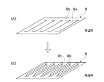
上記保護板8には、図2(A)に示すように、複数の切り込み8aが並列に形成されている。本実施形態では、各切り込み8aは、長方形の帯状パターンの3辺、特に1つの長辺と両端の2つの短辺を切り抜いた形状に形成されている。したがって、切り込み8aで囲まれた切り込み片8bは、長方形の帯状パターンの残った1つの長辺で他の部分と連結され、ここを基端として折り曲げ可能とされている。
【0024】
この保護板8は、先にも述べたように、熱膨張率の異なる2種類の金属板を積層した金属積層板からなるものであり、図3(A)に示すように、図中下側に熱膨張率の高い金属板9が配置され、上側に熱膨張率の低い金属板10が配置されるように積層されている。したがって、温度が上昇すると、いわゆるバイメタルの作用により、図2(B)及び図3(B)に示すように、各切り込み8aで囲まれた切り込み片8bが反り返り、次第に立ち上がって保護板8に開口部8cが形成された状態になる。
【0025】
本実施形態では、この保護板8は、改質反応器の製造過程において反応用フィン5にスラリー等を塗布して触媒を担持させるときに、水素分離膜6の表面に直接スラリーが触れて水素分離膜6を損傷することを防止するために設けている。すなわち、常温時は、保護板8には金属板9と金属板10との熱膨張差による歪みがなく、平面状態が確保されているため、図2(A)に示すように、各切り込み片8bによって開口部8cは塞がれた状態となる。したがって、保護板8は仕切板としての役割を果たし、触媒を含むスラリー等が水素分離膜6に接触することがない。また、この状態では保護板8が触媒の担持を阻害することもない。
【0026】
一方、高温時(改質反応器の運転時)には、図2(B)に示すように、金属板9と金属板10の熱膨張率の差に起因する熱歪みによって保護板8の切り込み片8bが反り返り、保護板8の開口部8cが開口状態となる。したがって、改質触媒層3の触媒作用による改質反応で生成した改質ガスが開口部8cにおいて水素分離膜6と接触し、水素ガスを速やかに分離抽出することができる。
【0027】
また、運転負荷が高くなり改質反応器の温度が上がってくると、切り欠き片8bが反る量が増え、水素分離をより積極的に行えるようになるため、負荷に適した状態になる。
【0028】
なお、本実施形態において、切り込み片8bが反る方向は改質触媒層3側にしている。これは、逆にすると水素分離膜6を傷つける虞れがあるためである。逆にした場合(水素分離膜6側に反るようにした場合)でも空間を十分に設ければ以上の問題を回避することができるが、この場合には改質反応器のサイズが大きくなることから、切り込み片8bが改質触媒層側に反るように設計することが好ましい。
【0029】
以上説明したように、本実施形態では、改質触媒層3と水素分離膜6との間に保護板8を挟み込んだ構成にしているため、製造過程において改質触媒層3の反応用フィン5に塗布するスラリーが水素分離膜6に触れて、水素分離膜6に損傷を与えるといった問題を未然に回避することができる。また、保護板8は、触媒担持後の改質反応器運転時には熱によって切り込み片8bが立ち上がり、開口部8cが開口するようになっているので、改質反応によって生成された改質ガスはこの開口部8cを通って水素分離膜6に接触して水素が分離されることになり、水素分離機能が損なわれることはない。さらに、負荷が上がって反応温度が高くなると、切り込み片8bの立ち上がり量が大きくなり、改質触媒層3に流入した原料の流れに乱流が発生して改質反応が促進され、性能が向上するという効果も有する。
【0030】
なお、保護板8の構成としては、以上の例に限らず、切り込み片8bが温度上昇に伴って立ち上がり変形するようなものであれば如何なるものであってもよい。例えば、熱膨張率の異なる3種類以上の金属板を積層した金属積層板を保護板8として用いるようにしてもよい。また、保護板8を形状記憶合金で形成することも可能である。改質触媒層3と水素分離膜6との間の保護板8として形状記憶合金を用いるようにした場合には、熱膨張率の異なる2種類の金属板を積層する必要がなくなり、構造をさらに簡略化することができる。
【0031】
(第2の実施形態)
本実施形態は、保護板8を熱膨張率の異なる金属板を積層するのではなく、切り込み片8bの付け根の部分にのみ熱膨張率の高い材料を埋め込み形成した例である。改質反応器の構造は、先の第1の実施形態のものと同じであるので、ここではその説明は省略する。
【0032】
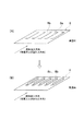
本実施形態では、図4(A)及び図4(B)に示すように、切り込み片8bの付け根部分にのみ熱膨張率の高い熱膨張材料8dを埋め込んでいる。この熱膨張材料8dは、保護板8を構成する他の部分の材料よりも熱膨張率が高く、温度上昇時には、図5(A)及び図5(B)に示すように、熱膨張材料8dの熱膨張により切り込み片8bが立ち上がり、開口部8cが開口される。
【0033】
本実施形態のように、切り込み片8bの付け根部分にのみ熱膨張材料8dを埋め込み形成した場合、切り込み片8bが立ち上がり変形するとき、大きな曲げが発生するのは根元部分のみであり、その他の部分にはほとんど曲げが発生しない。そのため、曲げ歪によって触媒が剥がれ落ちる量を最小にすることができる。
【0034】
(第3の実施形態)
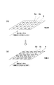
本実施形態は、切り込み8aを保護板8の全面に設けるのではなく、改質触媒層3に流入する原料ガスの流入方向、すなわち、改質触媒層3の改質ガスの流れる方向の下流側にのみ設けるようにした例である。改質反応器の構造は、先の第1の実施形態のものと同じであるので、ここではその説明は省略する。
【0035】
図6(A)及び図6(B)は、本実施形態の保護板8の形状を示すものである。保護板8に切り込み8aが形成され、切り込み片8bが温度上昇によって立ち上がり変形することは、先の第1の実施形態のものと同様である。ただし、本実施形態では、保護板8の切り込み8aは、原料ガスの流入方向(改質ガスが流れる方向)の下流側の領域にのみ形成されており、上流側の領域には形成されていない。
【0036】
改質反応器の上流側では改質反応が不十分で水素が十分に生成されていない場合が多く、このような状況で改質ガスを水素分離膜6に接触させると、水素分圧が不足するため、水素ガス通路7から改質触媒層3へと水素が逆流してしまう虞れがある。そこで、本実施形態では、保護板8の上流側の部分には開口部8cが形成されないようにして、改質ガスが水素分離膜6に接触することを防止し、それにより水素の逆流を防ぐようにしている。
【0037】
本実施形態のように、原料ガスの流入方向(改質ガスが流れる方向)の下流側にのみ切り込み8aが設けられた保護板8を用いることで、改質が十分に行なわれ水素分圧が十分な状態の改質ガスのみを水素分離膜6に接触させることができ、それによって水素を効率良く分離抽出することができ、また水素が改質触媒層3側に逆流することを防止することができる。
【0038】
(第4の実施形態)
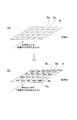
本実施形態は、切り込み片8bを原料ガス(改質ガス)の流れに平行するように設けるのではなく、原料ガス(改質ガス)の流れに対して向かい合うように形成するようにした例である。改質反応器の構造は、先の第1の実施形態のものと同じであるので、ここではその説明は省略する。
【0039】
本実施形態では、図7(A)及び図7(B)に示すように、切り込み8aの形状を略方形状とし、多数の切り込み8aを保護板8の全面に均等に配置している。各切り込み8aは、これによって形成される切り込み片8bの連結部である基端部が原料ガスの流入方向(改質ガスが流れる方向)の下流側に、これとは反対側の先端部が上流側になるように形成されている。したがって、図7(B)に示すように、切り込み片8bが立ち上がり変形した際には、原料ガス(改質ガス)の流れに向かい合うようになる。その結果、改質触媒層3で生成された改質ガスの流れを、切り込み片8bを利用して積極的に水素分離膜6側に導くことができ、水素分離速度を促進して改質反応器の性能を向上させることができる。
【0040】
なお、本実施形態の変形例として、図8(A)及び図8(B)に示すように、切り込み片8bの立ち上がり変形量が、改質ガスの流れる方向の下流側に向かうにしたがって次第に大きくなるように設計することも可能である。本例の相違点は、保護板8の切り込み片8bの反り量である。例えば、保護板8として積層する2種類の材料の膨張係数差を上流側と下流側とで異なるものにしている。具体的には、上流側の膨張率差を小さく、下流側の膨張率差を大きくする。このように保護板8の膨張率差を上流側と下流側とで異ならせることで、温度上昇した際に、図8(B)に示すように、上流側の切り込み片8bの反り量は小さく、下流側の切り込み片8bの反り量は大きくなる。
【0041】
改質触媒層3内での反応は、上流側は改質が十分に進んでいないので、水素が逆流するほどではないとしても、水素ガス通路7との水素分圧が小さいと考えられる。その状態では、積極的に改質ガスを水素分離膜6に供給するよりも、改質反応を進めることに重点をおいた方がよく、このような観点から、上流側では切り込み片8bの反り量を小さくしている。逆に、下流側では改質が十分に進んでいるので、積極的に水素分離を行なわせることが望ましく、そのため、切り込み片8bの反り量を大きくしている。このようにすることで、改質反応と水素分離を効率良く行うことが可能である。
【0042】
なお、以上の例では、保護板8として積層する2種類の材料の膨張係数差を異なるものにすることで切り込み片8bの立ち上がり変形量を制御しているが、これに限らず、例えば第2の実施形態と同様、各切り込み片8bの根元部分に熱膨張率の高い熱膨張材料を埋め込み、その埋め込み量や埋め込み材料の種類を変更することで立ち上がり変形量を制御するようにしてもよい。
【0043】
(第5の実施形態)
本実施形態は、保護板8に触媒を弾く触媒剥離材層を形成するようにした例である。改質反応器の構造や保護板8の形状は、先の第1の実施形態のものと同じであるので、ここではその説明は省略する。
【0044】
本実施形態では、図9(A)乃至図9(C)に示すように、保護板8の表面に触媒剥離材層11が形成されている。この触媒剥離材層11は、保護板8の改質触媒層3側の表面に形成されればよい。触媒剥離材層11を構成する材料としては、触媒を弾く性質のものであれば如何なるものであってもよく、例えばフッ素化合物からなる溶液やペースト、油類等を挙げることができる。触媒剥離材層11は、これらの材料を例えば保護板8の表面に塗布することにより形成される。
【0045】
図9(A)は、触媒剥離材層11を保護板8の改質触媒層3側の表面の全面に形成した例である。また、図9(B)は、触媒剥離材層11を切り込み片8bの表面にのみ形成した例である。何れの場合にも、触媒剥離材層11の作用によって、立ち上がり変形する部分に触媒が付着することがなくなる。したがって、改質反応器の運転時に切り込み片8bが変形したときに、曲げ歪みによって付着した触媒が剥がれ落ち、それが水素分離膜6上に落ちて水素分離膜6を損傷するのを防止することができる
なお、保護板8の構造が先の第2の実施形態のようなものである場合、すなわち、各切り込み片8bの根元部分に熱膨張率の高い熱膨張材料を埋め込んだ構造である場合には、図9(C)に示すように、切り込み片8bの基端部(根元部分)にのみ触媒剥離材層11を形成するようにしてもよい。この場合には、切り込み片8bの変形部分に触媒剥離材層11が形成されるので、この部分への触媒の付着を防止することができ、曲げ歪みによる触媒の剥がれ落ちを防止することができる。
【図面の簡単な説明】
【図1】改質反応器の概略構成を示す模式図である。
【図2】第1の実施形態の保護板の形状を示す斜視図であり、(A)は平面状態、(B)は切り込み片立ち上がり状態を示す。
【図3】第1の実施形態の保護板の形状を示す断面図であり、(A)は平面状態、(B)は切り込み片立ち上がり状態を示す。
【図4】第2の実施形態の保護板の平面状態での形状を示すものであり、(A)はこの保護板の斜視図、(B)は(A)におけるA−A線断面図である。
【図5】第2の実施形態の保護板の切り込み片立ち上がり状態での形状を示すものであり、(A)はこの保護板の斜視図、(B)は(A)におけるB−B線断面図である。
【図6】第3の実施形態の保護板の形状を示す斜視図であり、(A)は平面状態、(B)は切り込み片立ち上がり状態を示す。
【図7】第4の実施形態の保護板の形状を示す斜視図であり、(A)は平面状態、(B)は切り込み片立ち上がり状態を示す。
【図8】第4の実施形態の変形例における保護板の形状を示す斜視図であり、(A)は平面状態、(B)は切り込み片立ち上がり状態を示す。
【図9】第5の実施形態の保護板における触媒剥離材層の形成状態を示す斜視図であり、(A)は保護板表面の全面に塗布した状態、(B)は切り込み片にのみ塗布した状態、(C)は切り込み片の基端部にのみ塗布した状態を示す。
【符号の説明】
1 改質反応部
2 水素抽出部
3 改質触媒層
4 燃焼触媒層
5 反応用フィン
6 水素分離膜
7 水素ガス通路
8 保護板
8a 切り込み
8b 切り込み片
8c 開口部
8d 熱膨張材料
11 触媒剥離材層[0001]
TECHNICAL FIELD OF THE INVENTION
The present invention relates to a reforming reactor for reforming a raw material such as methanol to generate hydrogen, and more particularly to a technique for preventing damage to a hydrogen separation membrane.
[0002]
[Prior art]
There is known a so-called methanol reforming type fuel cell system in which methanol as a raw material is reformed to generate hydrogen, and the obtained hydrogen is supplied to a fuel cell to generate power. In this methanol reforming type fuel cell system, a reforming reactor for reforming methanol is required, and as a reforming reactor capable of ensuring a sufficient methanol decomposition rate even at a low temperature, for example, a patent document A plate-fin type reactor for non-equilibrium reaction as disclosed in No. 1 has been developed.
[0003]
This plate-fin type reactor for non-equilibrium reaction is configured by laminating a heat medium passage on one side and a decomposition product gas passage on the other side with a reactant passage interposed therebetween. the fin coated catalyst of the inner decompose methanol, CO, to produce a H 2. Between the reactant passage and decomposition product gas passage, the hydrogen separation membrane is provided, thereby it is possible to extract only the H 2.
[0004]
[Patent Document 1]
JP-A-6-345404
[Problems to be solved by the invention]
By the way, in the plate-fin type reactor for non-equilibrium reaction as described above, a reforming reaction section having a reforming catalyst layer serving as a reactant passage and a hydrogen separation membrane for separating hydrogen are provided in contact with each other. Due to this structure, the hydrogen separation membrane may be damaged at the time of fabrication, and its performance may be significantly reduced. That is, since the reforming reaction section and the hydrogen separation membrane are laminated without any partition, when the slurry containing the catalyst is applied in the passage of the reactant to form the reforming catalyst layer, the slurry is The possibility of contact with the separation membrane is high. For this reason, when the slurry accidentally touches the hydrogen separation membrane, the surface of the hydrogen separation membrane is eroded and damaged by the slurry, which causes a problem that the performance is greatly impaired.
[0006]
The present invention has been proposed for the purpose of overcoming such disadvantages of the prior art, and can reliably prevent damage to the hydrogen separation membrane at the time of production and the like. It is an object of the present invention to provide a reforming reactor capable of promoting the reforming and improving the reforming performance.
[0007]
[Means for Solving the Problems]
In order to achieve the above object, in the present invention, a reforming reaction section that reforms a raw material flowing into a reforming catalyst layer to generate a reformed gas, and a reforming gas generated in the reforming reaction section In a reforming reactor having a hydrogen separation membrane for separating hydrogen, a protection plate provided with a cut is sandwiched between the reforming catalyst layer and the hydrogen separation membrane in the reforming reaction section. The protection plate has an opening formed by a cut piece formed by the cut rising with an increase in temperature.
[0008]
In the reforming reactor of the present invention as described above, the protection plate is kept in a flat state during the manufacturing process, and functions as a partition plate for separating the reforming reaction section and the hydrogen separation membrane. Therefore, when the slurry containing the catalyst is applied to form the reforming catalyst layer, the slurry does not inadvertently come into contact with the hydrogen separation membrane.
[0009]
On the other hand, during the operation of the reforming reactor, the temperature of the reforming reaction section is increased in order to promote the decomposition reaction of the raw material, but the heat gradually raises the cut pieces of the protective plate, and an opening is formed in the protective plate. You. Therefore, the reformed gas generated in the reforming reaction section comes into contact with the hydrogen separation membrane through the opening, and hydrogen is separated from the reformed gas by the action of the hydrogen separation membrane and is taken out to the outside. .
[0010]
【The invention's effect】
In the present invention, since the protective plate is sandwiched between the reforming catalyst layer and the hydrogen separation membrane in the reforming reaction section to partition between them, the slurry may inadvertently come into contact with the hydrogen separation membrane. In addition, it is possible to reliably prevent the hydrogen separation membrane from being damaged at the time of fabrication or the like.
[0011]
When the reforming reactor is in operation, the notch on the protection plate rises to form an opening, so the reformed gas generated in the reforming reaction section is brought into contact with the hydrogen separation membrane to separate hydrogen quickly. -It is possible to extract, promote the reforming reaction and realize excellent reforming performance.
[0012]
BEST MODE FOR CARRYING OUT THE INVENTION
Hereinafter, a reforming reactor to which the present invention is applied will be described with reference to the drawings.
[0013]
(1st Embodiment)
FIG. 1 shows a specific structure of the reforming reactor of the present embodiment. The reforming reactor of the present embodiment is roughly divided into a reforming reaction section 1 that reforms a raw material (eg, methanol gas) to generate a hydrogen-rich reformed gas, and separates hydrogen from the generated reformed gas. And a hydrogen extraction unit 2 for taking out.
[0014]
The reforming reaction section 1 includes a reforming catalyst layer 3 in which a raw material flows to perform a reforming reaction, and a combustion catalyst layer 4 provided in contact with one surface of the reforming catalyst layer 3. The catalyst layer 3 is provided with reaction fins 5 coated with a reforming catalyst.
[0015]
The reforming catalyst coated on the reaction fin 5 functions as a reaction catalyst in the reforming reaction, and is formed, for example, by applying a slurry containing the reforming catalyst onto the reaction fin 5. The reforming catalyst may be appropriately selected depending on the type of the raw material and the type of the reforming reaction. For example, in the case of a low-temperature reforming reaction using methanol as a raw material, a noble metal-based catalyst such as Pt or Cu-Cr A system catalyst or the like can be used.
[0016]
The combustion catalyst layer 4 plays a role of supplying thermal energy for promoting the reforming reaction in the reforming catalyst layer 3, and the raw material necessary for the combustion reaction flows into the combustion catalyst layer 4 here. I have. For example, since the reforming reaction using methanol as a raw material is an endothermic reaction, the heat required for this is covered by the heat generated as a result of the exothermic reaction in the combustion catalyst layer 4. Note that a heat medium passage may be provided in place of the combustion catalyst layer 4 and necessary heat may be supplied by circulating a heat medium (for example, exhaust heat gas or the like) through the heat medium passage.
[0017]
In the reforming reactor of this embodiment, when methanol gas as a raw material flows into the reforming catalyst layer 3, a methanol reforming reaction (steam reforming) is performed in the reforming catalyst layer 3, and hydrogen-rich reforming is performed. Gas is generated. At this time, only hydrogen is extracted from the generated reformed gas by the hydrogen extraction unit 2, and the reforming reaction proceeds while repeating this. In the case of a reforming reactor that does not extract hydrogen, the composition of the generated gas is determined by the composition of the raw material, the reaction temperature, and the pressure (equilibrium composition). On the other hand, when hydrogen is extracted outside the reaction system by the hydrogen extraction unit 2 as in the reforming reactor of the present embodiment, the gas remaining in the reaction system shifts to a new equilibrium composition. By repeating this, more hydrogen can be generated.
[0018]
The hydrogen extraction unit 2 is provided on the other surface of the reforming catalyst layer 3, that is, on the surface opposite to the surface in contact with the combustion catalyst layer 4. The hydrogen extraction unit 2 includes a hydrogen separation membrane 6 for separating hydrogen, and a hydrogen gas passage 7 for extracting separated hydrogen, and is disposed so that the hydrogen separation membrane 6 is close to the reforming catalyst layer 3. I have.
[0019]
As the hydrogen separation membrane 6, a material in which a surface of a palladium-based material or the like is coated with a porous material or the like can be used. Hydrogen permeation in the hydrogen separation membrane 6 is caused by a hydrogen partial pressure difference between the primary side (the reforming catalyst layer 3 side) and the secondary side (the hydrogen gas passage 7 side) of the membrane. Therefore, when the reforming reaction proceeds in the reforming catalyst layer 3 and the hydrogen partial pressure on the reforming catalyst layer 3 side is increased, hydrogen is extracted from the reformed gas by that amount and extracted to the hydrogen gas passage 7 side. Will be.
[0020]
In the reforming reactor having the above-described configuration, the raw material methanol gas flows into the reforming catalyst layer 3. When the methanol gas flows into the reforming catalyst layer 3, the methanol gas comes into contact with the reforming catalyst on the surface of the reaction fin 5 while receiving the heat from the combustion catalyst layer 4 and raising the temperature. Then, the reforming reaction proceeds by the action of the reforming catalyst, and a hydrogen-rich reformed gas is generated. When the hydrogen-rich reformed gas is generated, only the hydrogen gas from the reformed gas enters the hydrogen gas passage 7 through the hydrogen separation membrane 6 and is separated from other decomposition reaction products and unreacted raw material gas. Collected. The recovered hydrogen gas is used, for example, as fuel for a fuel cell.
[0021]
The basic configuration of the reforming reactor has been described above. In the present embodiment, protection is provided between the reforming reaction section 1 and the hydrogen extraction section 2, that is, between the reforming catalyst layer 3 and the hydrogen separation membrane 6. The plate 8 is sandwiched therebetween and functions as a partition plate for partitioning these. Hereinafter, the protection plate 8 will be described in detail.
[0022]
The protection plate 8 is formed of a metal laminate in which two types of metal plates having different coefficients of thermal expansion are laminated, and maintains a flat shape at normal temperature. The protection plate 8 is overlaid on the hydrogen separation membrane 6, on which the reforming catalyst layer 3 of the reforming reaction section 1 is installed.
[0023]
As shown in FIG. 2A, a plurality of cuts 8a are formed in the protective plate 8 in parallel. In the present embodiment, each cut 8a is formed in a shape obtained by cutting out three sides of a rectangular band-shaped pattern, particularly one long side and two short sides at both ends. Therefore, the notch piece 8b surrounded by the notch 8a is connected to the other portion at the remaining one long side of the rectangular band-shaped pattern, and can be bent using this as a base end.
[0024]
As described above, the protective plate 8 is formed of a metal laminate in which two types of metal plates having different coefficients of thermal expansion are laminated, and as shown in FIG. Are stacked such that a metal plate 9 having a high coefficient of thermal expansion is disposed on the upper side, and a metal plate 10 having a low coefficient of thermal expansion is disposed on the upper side. Therefore, when the temperature rises, as shown in FIGS. 2B and 3B, the cut pieces 8b surrounded by the cuts 8a warp due to the so-called bimetal action, and gradually rise up to open the protective plate 8. The state where the portion 8c is formed is obtained.
[0025]
In the present embodiment, when the slurry is directly applied to the surface of the hydrogen separation membrane 6 when the slurry or the like is applied to the reaction fins 5 to support the catalyst in the manufacturing process of the reforming reactor, It is provided to prevent the separation film 6 from being damaged. That is, at normal temperature, since the protective plate 8 is not distorted due to a difference in thermal expansion between the metal plate 9 and the metal plate 10 and a flat state is secured, as shown in FIG. The opening 8c is closed by 8b. Therefore, the protection plate 8 functions as a partition plate, and the slurry or the like containing the catalyst does not come into contact with the hydrogen separation membrane 6. Further, in this state, the protection plate 8 does not hinder the loading of the catalyst.
[0026]
On the other hand, when the temperature is high (during the operation of the reforming reactor), as shown in FIG. 2 (B), the protection plate 8 is cut by thermal distortion caused by the difference in the coefficient of thermal expansion between the metal plate 9 and the metal plate 10. The piece 8b warps, and the opening 8c of the protection plate 8 is opened. Therefore, the reformed gas generated by the reforming reaction by the catalytic action of the reforming catalyst layer 3 comes into contact with the hydrogen separation membrane 6 at the opening 8c, and the hydrogen gas can be separated and extracted quickly.
[0027]
In addition, when the operating load increases and the temperature of the reforming reactor increases, the amount of warping of the notch pieces 8b increases, and hydrogen separation can be more positively performed. .
[0028]
In this embodiment, the direction in which the cut pieces 8b warp is on the reforming catalyst layer 3 side. This is because, if reversed, the hydrogen separation membrane 6 may be damaged. The above problem can be avoided if the space is provided sufficiently even in the case where it is reversed (when it is warped to the hydrogen separation membrane 6 side), but in this case, the size of the reforming reactor becomes large. For this reason, it is preferable that the cut piece 8b is designed to be warped toward the reforming catalyst layer.
[0029]
As described above, in the present embodiment, since the protection plate 8 is interposed between the reforming catalyst layer 3 and the hydrogen separation membrane 6, the reaction fins 5 of the reforming catalyst layer 3 in the manufacturing process. The problem that the slurry applied to the hydrogen separation membrane 6 touches the hydrogen separation membrane 6 and damages the hydrogen separation membrane 6 can be avoided beforehand. In addition, the protection plate 8 is configured such that the cut piece 8b rises due to heat when the reforming reactor is operated after the catalyst is loaded, and the opening 8c is opened. The hydrogen is separated by contacting the hydrogen separation membrane 6 through the opening 8c, and the hydrogen separation function is not impaired. Further, when the load rises and the reaction temperature rises, the rising amount of the cut pieces 8b becomes large, and turbulence occurs in the flow of the raw material flowing into the reforming catalyst layer 3, thereby promoting the reforming reaction and improving the performance. It also has the effect of doing.
[0030]
The configuration of the protection plate 8 is not limited to the above example, and may be any configuration as long as the cut piece 8b rises and deforms with a rise in temperature. For example, a metal laminate in which three or more types of metal plates having different coefficients of thermal expansion are laminated may be used as the protection plate 8. Further, the protection plate 8 can be formed of a shape memory alloy. When a shape memory alloy is used as the protective plate 8 between the reforming catalyst layer 3 and the hydrogen separation membrane 6, there is no need to laminate two types of metal plates having different coefficients of thermal expansion. It can be simplified.
[0031]
(Second embodiment)
This embodiment is an example in which a material having a high coefficient of thermal expansion is embedded and formed only in the base of the cut piece 8b, instead of laminating metal plates having different coefficients of thermal expansion on the protective plate 8. Since the structure of the reforming reactor is the same as that of the first embodiment, the description is omitted here.
[0032]
In this embodiment, as shown in FIGS. 4A and 4B, a thermal expansion material 8d having a high thermal expansion coefficient is embedded only in the base of the cut piece 8b. This thermal expansion material 8d has a higher thermal expansion coefficient than the material of the other parts constituting the protective plate 8, and when the temperature rises, as shown in FIGS. 5A and 5B, the thermal expansion material 8d The cut piece 8b rises due to the thermal expansion of the opening, and the opening 8c is opened.
[0033]
As in the present embodiment, when the thermal expansion material 8d is buried only in the base portion of the cut piece 8b, when the cut piece 8b rises and deforms, large bending occurs only in the base portion, and other portions are generated. Hardly bends. Therefore, it is possible to minimize the amount of the catalyst that peels off due to bending strain.
[0034]
(Third embodiment)
In the present embodiment, the cut 8 a is not provided on the entire surface of the protective plate 8, but on the downstream side in the direction in which the raw material gas flows into the reforming catalyst layer 3, that is, in the direction in which the reformed gas flows in the reforming catalyst layer 3. This is an example in which only one is provided. Since the structure of the reforming reactor is the same as that of the first embodiment, the description is omitted here.
[0035]
FIGS. 6A and 6B show the shape of the protection plate 8 of the present embodiment. The cut 8a is formed in the protective plate 8, and the cut piece 8b rises and deforms due to a rise in temperature, as in the first embodiment. However, in the present embodiment, the cut 8a of the protection plate 8 is formed only in the downstream region in the inflow direction of the raw material gas (the direction in which the reformed gas flows), and is not formed in the upstream region. .
[0036]
On the upstream side of the reforming reactor, the reforming reaction is often insufficient and hydrogen is not sufficiently generated. In such a situation, when the reformed gas is brought into contact with the hydrogen separation membrane 6, the hydrogen partial pressure becomes insufficient. Therefore, there is a possibility that hydrogen may flow backward from the hydrogen gas passage 7 to the reforming catalyst layer 3. Thus, in the present embodiment, the opening 8c is not formed in the upstream portion of the protection plate 8, thereby preventing the reformed gas from contacting the hydrogen separation membrane 6, thereby preventing the backflow of hydrogen. Like that.
[0037]
As in the present embodiment, by using the protective plate 8 provided with the cut 8a only on the downstream side in the source gas inflow direction (the direction in which the reformed gas flows), the reforming is sufficiently performed and the hydrogen partial pressure is reduced. Only the reformed gas in a sufficient state can be brought into contact with the hydrogen separation membrane 6, whereby hydrogen can be efficiently separated and extracted, and the hydrogen can be prevented from flowing back to the reforming catalyst layer 3 side. Can be.
[0038]
(Fourth embodiment)
The present embodiment is an example in which the cut pieces 8b are not provided so as to be parallel to the flow of the source gas (reformed gas), but are formed so as to face the flow of the source gas (reformed gas). is there. Since the structure of the reforming reactor is the same as that of the first embodiment, the description is omitted here.
[0039]
In the present embodiment, as shown in FIGS. 7A and 7B, the shape of the cut 8a is substantially rectangular, and a large number of cuts 8a are uniformly arranged on the entire surface of the protective plate 8. In each of the cuts 8a, a base end, which is a connecting portion of the cut pieces 8b formed thereby, is on the downstream side in the raw material gas inflow direction (the direction in which the reformed gas flows), and the distal end on the opposite side is upstream. It is formed to be on the side. Therefore, as shown in FIG. 7B, when the cut piece 8b rises and deforms, it comes to face the flow of the raw material gas (reformed gas). As a result, the flow of the reformed gas generated in the reforming catalyst layer 3 can be positively guided toward the hydrogen separation membrane 6 by using the cut pieces 8b, and the reforming reaction speed is enhanced by promoting the hydrogen separation speed. The performance of the vessel can be improved.
[0040]
As a modified example of the present embodiment, as shown in FIGS. 8A and 8B, the rising deformation amount of the cut piece 8b gradually increases toward the downstream side in the direction in which the reformed gas flows. It is also possible to design to be. The difference in this example is the amount of warpage of the cut piece 8b of the protection plate 8. For example, the difference in expansion coefficient between the two types of materials laminated as the protective plate 8 is different between the upstream side and the downstream side. Specifically, the difference in the expansion rate on the upstream side is reduced, and the difference in the expansion rate on the downstream side is increased. By making the expansion coefficient difference of the protection plate 8 different between the upstream side and the downstream side in this way, when the temperature rises, the amount of warpage of the cut 8b on the upstream side is small as shown in FIG. However, the amount of warpage of the cut piece 8b on the downstream side increases.
[0041]
In the reaction in the reforming catalyst layer 3, since the reforming does not proceed sufficiently on the upstream side, it is considered that the hydrogen partial pressure with the hydrogen gas passage 7 is small even if the hydrogen does not flow backward. In this state, it is better to focus on the progress of the reforming reaction rather than actively supplying the reformed gas to the hydrogen separation membrane 6, and from such a viewpoint, the warpage of the cut pieces 8b on the upstream side. The amount has been reduced. Conversely, since the reforming has sufficiently progressed on the downstream side, it is desirable to actively perform hydrogen separation, and therefore, the amount of warpage of the cut pieces 8b is increased. By doing so, it is possible to efficiently perform the reforming reaction and the hydrogen separation.
[0042]
In the above example, the rising deformation amount of the cut piece 8b is controlled by making the expansion coefficient difference between the two kinds of materials laminated as the protective plate 8 different. However, the present invention is not limited to this. Similarly to the above embodiment, a thermal expansion material having a high coefficient of thermal expansion may be embedded in the root portion of each cut piece 8b, and the amount of rising deformation may be controlled by changing the amount of embedding and the type of embedding material.
[0043]
(Fifth embodiment)
The present embodiment is an example in which a catalyst release material layer for repelling a catalyst is formed on a protective plate 8. Since the structure of the reforming reactor and the shape of the protective plate 8 are the same as those of the first embodiment, the description is omitted here.
[0044]
In the present embodiment, as shown in FIGS. 9A to 9C, the catalyst release material layer 11 is formed on the surface of the protective plate 8. The catalyst release material layer 11 may be formed on the surface of the protective plate 8 on the side of the reforming catalyst layer 3. The material constituting the catalyst release material layer 11 may be any material as long as it has a property of repelling a catalyst, and examples thereof include a solution, paste, and oils made of a fluorine compound. The catalyst release material layer 11 is formed by applying these materials to, for example, the surface of the protective plate 8.
[0045]
FIG. 9A shows an example in which the catalyst release material layer 11 is formed on the entire surface of the protective plate 8 on the side of the reforming catalyst layer 3. FIG. 9B is an example in which the catalyst release material layer 11 is formed only on the surface of the cut piece 8b. In any case, due to the action of the catalyst release material layer 11, the catalyst does not adhere to the portion that rises and deforms. Therefore, when the cut piece 8b is deformed during the operation of the reforming reactor, the attached catalyst is peeled off due to bending strain, and it is prevented that the catalyst falls on the hydrogen separation membrane 6 and damages the hydrogen separation membrane 6. In the case where the structure of the protection plate 8 is as in the second embodiment described above, that is, the structure in which a thermal expansion material having a high coefficient of thermal expansion is embedded in the base of each cut piece 8b. Alternatively, as shown in FIG. 9C, the catalyst release material layer 11 may be formed only at the base end (root portion) of the cut piece 8b. In this case, since the catalyst release material layer 11 is formed on the deformed portion of the cut piece 8b, it is possible to prevent the catalyst from adhering to this portion and prevent the catalyst from peeling off due to bending strain. .
[Brief description of the drawings]
FIG. 1 is a schematic diagram showing a schematic configuration of a reforming reactor.
FIGS. 2A and 2B are perspective views showing the shape of a protection plate according to the first embodiment, wherein FIG. 2A shows a planar state, and FIG.
FIGS. 3A and 3B are cross-sectional views illustrating the shape of the protection plate according to the first embodiment, wherein FIG. 3A illustrates a planar state, and FIG.
4A and 4B show a shape of a protection plate according to a second embodiment in a planar state, wherein FIG. 4A is a perspective view of the protection plate, and FIG. 4B is a cross-sectional view taken along line AA in FIG. is there.
5A and 5B show shapes of the protection plate according to the second embodiment in a cut piece rising state, in which FIG. 5A is a perspective view of the protection plate, and FIG. 5B is a cross-sectional view taken along line BB in FIG. FIG.
FIGS. 6A and 6B are perspective views showing a shape of a protection plate according to a third embodiment, wherein FIG. 6A shows a planar state, and FIG.
FIGS. 7A and 7B are perspective views showing the shape of a protection plate according to a fourth embodiment, wherein FIG. 7A shows a planar state, and FIG.
FIG. 8 is a perspective view showing a shape of a protection plate according to a modification of the fourth embodiment, wherein (A) shows a planar state, and (B) shows a cut piece rising state.
FIGS. 9A and 9B are perspective views showing a state in which a catalyst release material layer is formed on a protective plate of a fifth embodiment, wherein FIG. 9A is a state where the protective layer is applied to the entire surface of the protective plate, and FIG. (C) shows a state where it is applied only to the base end of the cut piece.
[Explanation of symbols]
Reference Signs List 1 reforming reaction section 2 hydrogen extraction section 3 reforming catalyst layer 4 combustion catalyst layer 5 reaction fin 6 hydrogen separation membrane 7 hydrogen gas passage 8 protection plate 8a cut 8b cut piece 8c opening 8d thermal expansion material 11 catalyst release material layer