【0001】
【発明の属する技術分野】
本発明は、光ディスク装置や撮像光学系に用いる光学素子の押圧成形による製造方法および成形に用いる光学素子成形用金型等に関するものである。
【0002】
【従来の技術】
光学素子成形用金型は、光学機能面を備えた一対の押圧型と前記一対の押圧型を摺動案内する胴型とで構成され、成形型内部にガラス材料を投入して、ガラス材料の軟化点近傍まで加熱した後、加圧を行って成形型の光学機能面をガラス材料に精密転写させて光学素子を得るものである。
【0003】
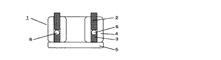
古くから、より生産性を向上させる提案として、特許文献1や特許文献2があり、何れも複数個の一対の押圧型と複数個の貫通孔を所定ピッチに配設した胴型とで構成され、複数個のガラス材料を一挙に成形する方法が開示されている。特許文献2に於いては、図7に示すように、ユニットモールド(成形型)1は上型2、下型3を摺動案内する胴型4および支持台5で構成され、前記ユニットモールドの内部に複数のガラス材料を投入し、加熱軟化したガラス材料6を一挙に加圧し、また前記ユニットモールドを複数個準備して生産性の高い光学素子の製造が行えるものである。
【0004】
【特許文献1】
特開昭61−227929号公報
【特許文献2】
特開昭62−70235号公報
【0005】
【発明が解決しようとする課題】
しかし、光学素子(以下、レンズに代表して記載する)に求められる精度要求は、年々高まってきており、例えば、レーザー光源を利用した光ディスク装置においては情報量を大量に取り扱おうとする高容量化と、それに伴う高NAレンズの実現が不可欠である。また、静止画や動画を扱う撮像光学系に用いるレンズに於いても、高画質化や高解像化と云ったトータルの機器精度がレンズに要求されている。
【0006】
また、機器の小型化を実現するためにレンズの小型化と、機器に直接取り付け可能な外形形状が求められ、丸形状以外のものも要望されている。それらを実現するための課題を要約すると、以下の3点である。
【0007】
課題1.レンズ両面の偏芯精度向上は極めて重要であり、従来例のように一対の押圧型と胴型とで成形型を構成した場合には、必然的に嵌合されるクリアランスを極めて小さく設計することで偏芯精度は向上される。しかし一方で一対の押圧型のどちらかを胴型から離脱させないと成形されたレンズの取り出しと、光学素子材料の投入が行えない。しかし、クリアランスを極限まで小さくすると成形型の組立、即ち成形型を胴型の貫通孔に嵌合させることが困難となり、嵌合の際に成形型を傷めてしまうと云う課題を有している。
【0008】
課題2.レンズの外形形状が回転軸対称(円形)以外のものを実現する為には成形型および胴型の貫通孔のレンズ外形形状に合致した形状が考えられるが、課題1と同様に成形型の組立が極めて難しいと云う課題を有している。
【0009】
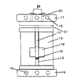
課題3.上記した、極めて高精度なレンズを市場の要望に応えられる低コストで実現するための製造法が確立されていない。
【0010】
【課題を解決するための手段】
請求項1に相当する解決手段は、光学機能面を備えた一対の成形型(一対の押圧型)を精密に摺動案内する貫通孔を備えた胴型に嵌合させ、前記貫通孔と直交して開口部を設け、一対の押圧型を貫通孔から離脱させずに光学素子材料および成形されたレンズの取り出しが行える構造の成形型で課題解決する。
【0011】
請求項2に相当する解決手段は、一対の押圧型を摺動案内する貫通孔を備えた第1の胴型と、レンズの外形形状を規制する第2の胴型を分離して設け、それぞれ別の作用をさせることで課題解決する。
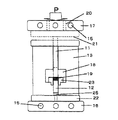
【0012】
請求項3に相当する解決手段は、前記第2の胴型に設けるレンズ外形の規制面が円または多角形で形成して課題解決する。
【0013】
請求項4に相当する解決手段は、前記第2の胴型を、第1の胴型もしくは一対の押圧型のどちらか一方に構成して課題解決する。
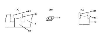
【0014】
請求項5に相当する解決手段は、一対の押圧型と前記一対の押圧型を摺動軸案内する貫通孔を備え、かつ前記貫通孔に直交して開口部を設けた第一の胴型とで構成される内部空間に光学素子材料を投入して成形ブロックを成す工程と、前記成形ブロック全体を加熱して前記光学素子材料の軟化点近傍で押圧成形する工程と、前記成形ブロック全体を所定温度まで冷却する工程と、前記開口部より成形されたレンズを前記一対の押圧型と前記貫通孔との嵌合を維持した状態で取り出す工程とを具備した光学素子の製造方法で解決手段とする。
【0015】
請求項6に相当する解決手段は、一対の押圧型もしくは一対の押圧型どちらか一方の複数型を複数の貫通孔に挿入されて摺動案内し、前記複数型に対応する他方の成形型を前記複数よりも少なく配置し、前記複数型と前記他方の成形型とでレンズの両面を形成するように前記貫通孔が所定ピッチに配設された胴型の、前記貫通孔に直交して開口部を設け、前記一対の押圧型を前記胴型の貫通孔から離脱させることなく、前記開口部が光学素子材料の投入および光学素子の取り出し口とすることで解決手段とする。
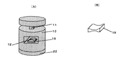
【0016】
請求項7に相当する解決手段は、前記所定ピッチを整列配置して解決手段とする。
【0017】
請求項8に相当する解決手段は、複数の一対の押圧型を一つの摺動案内する貫通孔に嵌合させた胴型形状とすることで解決手段とする。
【0018】
請求項9に相当する解決手段は、成形されるレンズの厚みを規制する第3の胴型で構成することで解決手段とする。
【0019】
請求項10に相当する解決手段は、請求項8で構成される光学素子用成形型と、金型吸着機能を備えた成形装置とを用い、前記成形型を前記成形装置に固定し、被成形材料を成形装置から取り出して後、機械加工をして複数のレンズに分断して得られる光学素子の製造方法で解決手段とする。
【0020】
請求項11に相当する解決手段は、複数の一対の押圧型を備えた成形型を加熱工程、加圧工程、冷却工程に順次搬送し、成形型を成形装置から分離して後、成形型から光学素子を取り出して、機械加工をして複数のレンズに分断して得られる光学素子の製造方法で解決手段とする。
【0021】
請求項12に相当する解決手段は、投入される光学素子材料が、一つのレンズを形成する個別のプリフォームもしくは複数の一対の押圧型に対応するように単一のプリフォームを投入することで解決手段とする。
【0022】
請求項13に相当する解決手段は、請求項5乃至請求項12の範囲で成形された光学素子を提供することで解決手段とする。
【0023】
【発明の実施の形態】
(実施の形態1)
図1は、実施の形態1を説明するもので、上型11、下型12を摺動案内する案内胴型13とで構成した光学素子成形用金型と、ヒータ15を埋設した下加熱板16および上加熱板17を介して矢印Pで示す図示しない加圧機構を備えた成形装置の一部を示す縦断面図である。案内胴型13には、上下型11および12と直交する開口部18が設けられている。下型12と上型11との間にはレンズ19が成形されている。上型11は上加熱板17に設けた図示しない真空装置などに連通する吸着口20に吸い上げられて、図中波線で示す位置に持ち上げられた状態である。
【0024】
レンズ19は、開口部18から挿入する別の吸着治具によって、案内胴型13内から取り出し、また光学素子材料を投入する事が出来る。このように、上下型を胴型から離脱させることなく成形が行える光学素子成形用金型であり、上下型と胴型のクリアランスを極限まで小さくしても、上型11の嵌合時における破損を皆無にし、またレンズ両面の偏芯精度を高めることが可能となる。
【0025】
具体的には、上下型11,12および案内胴型13には炭化タングステン材料を用い、上型11の成形面は球面凸形状で曲率半径が3.444mm、下型12の成形面には球面凹形状で曲率半径が4.458mmに精密に機械加工し、鏡面研磨して後、その表面に光学素子材料(以下ガラス材料と呼ぶ)であるガラス材料との溶着を防止するための白金系の合金膜を成膜している。上下型の外径を3.5mmとし、案内胴型13とのクリアランスを2ミクロン以下に設定するように加工した。光学素子材料には主成分が硼珪酸バリュームからなるガラス材料(屈伏点:549℃、ガラス転移点501℃)を外径2.75mmの球形状に研磨したものを準備した。
【0026】
上型11と下型12の間にガラス材料を投入し、上下の加熱板に通電し、成形金型全体を600℃まで昇温した状態で120秒間保持した後、図中Pの加圧力を800Nで加圧してガラス材料を変形し、上型の鍔部21と案内胴型13の上端面が当接するまで加圧を続けて成形を完了した。その後、加熱板への通電を中止して室温まで冷却した後に、外部吸引装置を作動し、上型11を図中波線で示される所まで持ち上げた状態で、真空ピンセットで光学素子を胴型から取り出した。
【0027】
メニスカス形状を示したレンズを、フィゾー型の光干渉計により透過波面収差を数十個測定したところ、平均値としてトータル波面収差0.06λ、非点収差0.023AMT、コマ収差0.011AMT、球面収差0.865AMTを示し、光ピックアップの光学系で使用したところ、実用上問題なく使用可能であることを確認した。従来における成形型と胴型とのクリアランスが6〜8ミクロンで成形を行ったものと比較して、クリアランスを小さく設定したことによるコマ収差の改善効果があった。また、クリアランスが2ミクロン以下の金型でも成形型と胴型とを組み立てる必要がなく、型に損傷を与えることが皆無となる。
【0028】
また、胴型は光学素子材料が配置される箇所の近傍が大きく開口しているため、加熱によってガラス材料からの揮発物が分散するので、成形された光学素子に曇りなどの欠陥がなく外観が極めてよい。尚、本実施の形態では上加熱板17に吸着口20を設け、真空吸着によって上型11を吸い上げて、レンズを取り出したが、その手順が成形装置から分離した状態で行っても同様のレンズが得られることに変わりはない。
【0029】
(実施の形態2)
図2は、実施の形態2を説明するもので、上型11、下型12を摺動案内する案内胴型13と、前記胴型に設けた開口部18、成形されたレンズ19などは図1で説明したものと同様で、同符号を用いている。下型12は単なる円柱形状の片側端面に光学機能面が形成されたものである。下型12は、その外径よりも小さな貫通孔25が中心に設けられた段付きの受け型22の上に載置されて、案内胴型13内に収容されている。案内胴型13の内部中央には規制胴型23が設けられ上下型11,12の中心軸と同軸上に、かつ案内胴型13に軽圧入されている。
【0030】
案内胴型13はレンズ両面の光軸を保証させるために機能し、規制胴型23はレンズの外形形状を規制させるために機能させる。下型12を円柱形状に、また受け型22に貫通孔25を設ける理由は、規制胴型23からレンズ19の取り外しを容易にするのに機能する。例えば細い押し棒などで下型12を介して、突き出しができるために、下型の光学機能面に載せたまま規制胴型23からレンズを取り出すことが容易になる。尚、規制胴型23も案内胴型13と同様の炭化タングステン材料で構成されている。
【0031】
具体的には、上下型11,12に形成した光学機能面の形状や外形寸法および成形されるガラス材料などは実施の形態1と同様のものを使用した。上下型と案内胴型とのクリアランスは2ミクロン以下に設定し、下型12と規制胴型23とのクリアランスは10ミクロンに設定した。
【0032】
下型12の光学機能面と規制胴型23の内面で形成される箇所にガラス材料を載置し、上下の加熱板に通電して600℃まで昇温した状態で120秒間保持した後、加圧力Pを800Nで成形した。成形型全体を冷却して後、成形装置から取り出し、受け型22に設けた貫通孔25から、下型12を上方に突き出して、レンズ19を規制胴型23から取り出した。その後、光学特性をフィゾー型の光干渉計で測定したところ、実施の形態1で得られたものとほぼ同様の特性を確認した。また光ピックアップの光学系で使用しても実用上問題のないものが成形されていた。
【0033】
(実施の形態3)
図3(A)は、規制胴型23の別の形態を示す部分図であり、案内胴型13と下型12とは2ミクロン以下のクリアランスで嵌合されており、下型12と規制胴型23のクリアランスは比較的大きなクリアランス10ミクロンで嵌合されている。レンズの外形形状を決定する規制面24は四角形状を成して彫り込まれており、また、その外径は案内胴型13に軽圧入されている。尚、彫り込みには型彫りの放電加工機を用いて加工を行った。
【0034】
図3(B)は、規制面24が形成された規制胴型23を用い、実施の形態1および2とほぼ同様の条件で成形されたレンズ19である。但し、ガラス材料は球形状のものを用いたが、その体積は所望に設計されている。得られたレンズ19は外形が四角形状を成しており、その四隅には適度なRが形成されており光学素子材料の体積を吸収していた。
【0035】
光学特性も実施の形態1,2と同様に確認したが、波面収差としては実用上問題となる特性は確認されなかった。
【0036】
尚、図3(C)に示すように、規制胴型23が下型12に軽圧入されてもよく、また、規制面24は丸形状の他、多角形に形成されても良い。更に上下型のどちらか一方に形成してもよいが、ガラス材料の載置に好適なのは下型である。上述したようにレンズの外形形状が特に多角形を成す成形金型に於いては、その多角形状を成形型の外形と案内胴型との嵌め合い状態で設けるよりも、規制胴型にその作用を持たせる方が得策である。尚、実施の形態1乃至3に於ける光学機能面は球面形状であるが、別段、回転軸対称の非球面形状であっても同様に実施出来るものである。
【0037】
(実施の形態4)
図4は、上型11、下型12、案内胴型13、開口部18、受け型22で構成された光学素子成形用金型を示す斜視図である。外形形状が四角形の上型11は、案内形状が角孔を成した案内胴型13と嵌合し、下型12は四角柱の形状で、角孔に嵌合され、上下型と角孔とは精密に摺動出来るようにしている。下型12の光学機能面は下側の角孔内に位置し、ガラス材料を保持できる空間が形成されている。
【0038】
上型および下型には凸状のシリンダー面が、それぞれ14Rと8Rにそれぞれ光学機能面として形成されている。上下型に形成したシリンダー面の母線の角度ずれが三分以内になるように、上下型と角孔とのクリアランスは2ミクロンの公差で嵌合されている。角孔の寸法は3.5mm角である。ガラス材料には、硼酸やランタンおよびタンタルなどの原料を多用した成分の特殊な光学材料(屈伏点:549℃、ガラス転移点510℃)で、案内胴型の角孔寸法より小さめで、1.2mm厚みで両面が鏡面状態に研磨された平板状のものを準備した。尚、受け型22の中心には図示しない貫通孔25が図2と同様に設けられている。
【0039】
実施の形態1乃至3と同様に、上記したガラス材料を金型内に投入して、成形金型全体を580℃まで昇温し、約60秒間保持した後に300Nの加圧力で成形した。成形金型全体を冷却して後、受け型22の貫通孔25から下型12を上方に突き出して成形されたレンズを取り出した。転写された凹状のシリンダー形状を三次元測定器で計測したところ、ほぼ光学機能面形状よりも小さく、図4(B)に示すような近似した曲率半径を有した形状のレンズ19を得ることが出来た。
【0040】
また、両母線の角度ずれは、レンズの外形を基準にし凹形状の母線までの距離を計測したところ、充分に三分以内に成形できていることが確認された。
【0041】
本発明では上型と案内胴型とが嵌合されたままレンズの取り出しと、ガラス材料の投入が行えるのものであり、通常、このように外形が角形状のものを従来例で示した構成の成形型で行うには、上型11と案内胴型13とを嵌合させるのが極めて難しく、また嵌合に際して上型を傷めてしまうと云う課題を完全に解決するものである。尚、本実施の形態では、シリンダー形状の母線を同じ方向のものを説明したが、互いの母線が直交する構成でも実施可能である。さらに、本実施の形態のように両面の回転位置決めが必要なものや、レンズ外形に対して片側面の回転位置決めが必要なレンズ成形に対して効果がある。
【0042】
(実施の形態5)
図5(A)、(B)は、複数個のレンズを成形するに好適な型構成と製造方法を説明する斜視図と要部断面図を示し、図5(A)は型構成の概念を説明するものである。所定ピッチに複数個が配置された上型11と、前記上型11を摺動案内する案内胴型13と、上型11に対応し、かつ複数個よりも少なく配置した下型12と、前記上型11の軸方向とは直交し、前記案内胴型13の側面に開口部18を備えている。開口部18はガラス材料およびレンズの取り出しに機能させる。
【0043】
図5(B)は、製造方法を説明するもので、上型11、下型12とこれら上下型を摺動案内する案内胴型13および上下型11,12の光学機能面の間に載置されたガラス材料99、成形されたレンズ19が図示されている。上下型と案内胴型およびガラス材料は一体に組み込まれ、ヒータ15が埋設された下加熱板16上に載置されており、その上方には上型11と接し、上型11を吸着させる吸着口20を備えた吸着板98と前記吸着板98が固定され、ヒータ15が埋設された上加熱板17とで構成されている。さらに、上加熱板17には図示しない、例えばエアーシリンダなどの駆動源に連結されている加圧機構95があり、図中矢印方向の+Z、−Z方向に上下自在に駆動する。ガラス材料99およびレンズ19は挟持具97、96を用いて案内胴型13への投入と案内胴型13からの取り出しに機能するものである。
【0044】
本実施の形態を具体的に説明する。図中左側に示すガラス材料99は硼珪酸バリューム系のガラス材料(屈伏点:549℃、ガラス転移点:501℃)を18×25×1.2mmの板状で、その両面を光学鏡面に加工したものを準備した。上下型11,12が案内胴型13に組み込まれた状態で下加熱板16上に載置し、吸着口20に連接する図示しない真空装置などを用いて上型11を吸着板98で吸着し、加圧機構95を+Z方向に持ち上げる。このとき上型11は案内胴型13からは離脱しない範囲である。上型を吸着した状態で、挟持具97を用いてガラス材料99を図中+X方向に移動させ、上下型の間に投入した後、加圧機構95を−Z方向に移動させ、さらに吸着を停止した。その後、上下のヒータ15に通電して上下加熱板16,17を600℃まで昇温し、その状態で120秒間保持した後に、加圧機構95で図中Pで示すように5000Nの加圧力で押圧し、ガラス材料を0.2mm変形させた。
【0045】
その後、ヒータ電源をオフにし、加圧を継続したままガラス転移点まで冷却した後に、加圧を中止してさらに室温まで冷却を継続した。その後、上型11を吸着板98で吸着したまま、加圧機構95で+Z方向に上型を持ち上げた状態で、挟持具96を−X方向に移動させ、成形されたレンズ19を挟んで+X方向に取り出した。複数個の転写面が成形されたレンズ19を、ダイヤモンド砥石を用いたダイシングソーによって所望のピッチに機械加工して分断し個別のレンズを得た。図5(C)は分断された個別のレンズ100を示し、上型11の光学機能面が転写された凹面形状101と、その反対面には凹形状のシリンダー面102とが転写され、レンズ100の外形は角形状を成している。
【0046】
尚、上型11に設けた光学機能面の形状はR15.6の凸形状の球面、また下型はR4.5凸シリンダー形状である。上型11に対応するレンズの転写面を光干渉計で評価したところ、λ/4程度の転写が確認され、一方、下型12に対応する凹形状の母線に直交する方向を三次元測定器で評価したところ、ほぼ金型の曲率に近似していることを確認した。光学機器への使用が可能で、かつ所望した特性であることが確認された。
【0047】
さらに、成形に用いた装置は詳細に図示しなかったが、上下加熱板の温度制御や加圧機構を用いた圧力制御、吸着板に連通した真空装置、また成形金型を加熱して押圧成形する部分は全体が不活性ガス中で行えるチャンバーを備えているものである。
【0048】
(実施の形態6)
図6(A)、(B)、(C)、(D)は複数のレンズを、かつ比較的、外形が小さなレンズを一挙に成形するのに好適な他の実施の形態を示す。(A)は型構成の斜視図、(B)は型構成の断面図、(C)はレンズの製造工程を説明する要部断面図、(D)は得られたレンズの斜視図である。(A)において複数個の上型11は整列配置されて案内胴型13の上方に開口する貫通孔81に隙間なく嵌合され、上下に摺動する構成である。複数個の下型12も案内胴型13の下方に開口する貫通孔82に整列配置され、案内胴型13とは嵌合している。案内胴型13の両端に開口する開口部18が設けられてガラス材料の投入や成形されたレンズの取り出しに機能させる。
【0049】
下型12の光学機能面83は凸状のシリンダー面が形成されており、その母線と、複数個配置された上型11の中心軸線とが合致するような寸法関係にしている。上型11の光学機能面は下型12のそれと対向して設けられており、互いの光学機能面の間にガラス材料を配置して加熱加圧して、複数個のレンズを一挙に成形し、その後、機械加工によって上型11の光学機能面に対応するように分断して行うレンズの製造方法である。尚、上型11の配置は別段、整列配置でなく、求めるレンズの形状によって選択されるが俵積みの配置にしても好適である。また下型12も本実施の形態のようなシリンダー面のように、個別のレンズに共通できる形状のみでなく、個別の形状面を有するものでも良い。
【0050】
本実施の形態を具体的に説明する。図6(B)のガラス材料99は硼珪酸バリューム系のガラス材料(屈伏点:549℃、ガラス転移点:501℃)を16×25×1.2mmの板状で、その両面を光学鏡面に加工したものを準備した。上下型11,12が案内胴型13に組み込まれた状態で、かつ上下型の間に配置して成形ブロック84を形成する。その後、図6(C)に示すように成形ブロック84はヒータ15が埋設された上下の加熱板16,17の間に置かれる。上下加熱板16,17の設定温度が600℃に保持されている加熱部85に成形ブロックを投入し180秒間保持して成形ブロック全体の加熱を行った。図中矢印Pは加圧機構95を示し、加熱時における加圧力Pは50Nとした。その後、成形ブロック84を別の温度設定がされている加圧部86に移送し(図中矢印方向)5000Nの加圧力Pで押圧成形した。
【0051】
さらに成形ブロックを、ガラス転移点近傍に温度設定された冷却部87に移送して加圧を継続したまま冷却を行った。その後、冷却部87から取り出された成形ブロック84を室温まで冷却し、複数個の光学機能面が転写されたレンズを得た。その後、複数個のレンズをダイシングソーによって個別のレンズに分断して、図6(D)に示すような外形が多角形状のレンズ100を得た。
【0052】
尚、上型11に設けた光学機能面の形状はR15.6の球面、また下型はR4.5の凸シリンダー形状である。上型11に対応するレンズの転写面を光干渉計で評価したところ、λ/3〜λ/4程度の転写が確認された。一方、下型12に対応する凹形状の母線と、上型11の光学機能面の中心とのずれ量を三次元測定器で評価したところ、約0.006mmが確認され、光学機器への使用が可能で、かつ所望した特性であることが確認された。
【0053】
実施の形態5と同様に、成形に用いた装置は詳細に図示しなかったが、上下加熱板の温度制御や加圧機構を用いた圧力制御、成形ブロックを順次移送する手段、また成形金型を加熱して押圧成形する部分は全体が不活性ガス中で行えるチャンバーに内包され、通常の技術手段で行えるものである。
【0054】
【発明の効果】
上記の実施の形態から明らかなように、光学機能面を有する一対の押圧型と前記一対の押圧型を摺動案内する胴型とで構成される金型において、押圧型を胴型から離脱させないことにより、嵌合クリアランスを極限まで小さくしても型の破損を招かない。従ってレンズ両面の光軸精度が高められることで高精度なレンズ成形が実現できる。また、レンズ外形が多角形のものにも適応可能であり、さらに、複数個のレンズを一挙に製造する手段として効果的である。よって、本発明は産業上利用価値の高い発明である。
【図面の簡単な説明】
【図1】実施の形態1の成形装置の縦断面図
【図2】実施の形態2の成形装置の縦断面図
【図3】(A)実施の形態3における規制胴型の別形態を示す図
(B)実施の形態3で成形されたレンズの斜視図
(C)実施の形態3における下型に軽圧入された規制胴型の断面図
【図4】(A)実施の形態4における光学素子成形用金型の斜視図
(B)実施の形態4で得られた近似した曲率半径を有した形状のレンズの斜視図
【図5】(A)実施の形態5における複数個のレンズを成形する型構成の斜視図
(B)実施の形態5における複数個のレンズを成形する型構成の要部断面図
(C)実施の形態5における分断された個別のレンズの斜視図
【図6】(A)実施の形態6における複数個のレンズを成形する型構成の斜視図
(B)実施の形態6における複数個のレンズを成形する型構成の断面図
(C)実施の形態6における複数個のレンズを成形する工程を示した図
(D)実施の形態6で得られた外形が多角形状のレンズの斜視図
【図7】従来の成形型の縦断面図
【符号の説明】
1 ユニットモールド(成形型)
2 上型
3 下型
4 胴型
5 支持台
6 ガラス材料
11 上型
12 下型
13 案内胴型
15 ヒータ
16 下加熱板
17 上加熱板
18 開口部
19 レンズ
20 吸着口
21 上型鍔部
22 受け型
23 規制胴型
24 規制面
25 貫通孔
81 貫通孔
82 貫通孔
83 光学機能面
84 成形ブロック
85 加熱部
86 加圧部
87 冷却部
95 加圧機構
96 挟持具
97 挟持具
98 吸着板
99 ガラス材料
100 レンズ
101 凹面形状
102 シリンダー面[0001]
TECHNICAL FIELD OF THE INVENTION
The present invention relates to a method for manufacturing an optical element used for an optical disk device or an imaging optical system by press molding, a mold for molding an optical element used for molding, and the like.
[0002]
[Prior art]
The optical element molding die is composed of a pair of pressing dies having an optical function surface and a body die that slides and guides the pair of pressing dies. After heating to near the softening point, pressure is applied to precisely transfer the optically functional surface of the mold to a glass material to obtain an optical element.
[0003]
As a proposal for improving productivity from a long time ago, there are Patent Literature 1 and Patent Literature 2, each of which is composed of a plurality of pairs of pressing dies and a trunk type in which a plurality of through holes are arranged at a predetermined pitch. A method of forming a plurality of glass materials at once is disclosed. In Patent Document 2, as shown in FIG. 7, a unit mold (molding die) 1 is composed of an upper die 2, a trunk die 4 for slidingly guiding a lower die 3, and a support base 5, and A plurality of glass materials are charged into the inside, the heat-softened glass material 6 is pressed at a stroke, and a plurality of the unit molds are prepared to manufacture an optical element with high productivity.
[0004]
[Patent Document 1]
JP-A-61-227929
[Patent Document 2]
JP-A-62-70235
[0005]
[Problems to be solved by the invention]
However, accuracy requirements for optical elements (hereinafter, typically represented as lenses) are increasing year by year. For example, in an optical disk device using a laser light source, a high capacity for handling a large amount of information is required. It is indispensable to realize the high NA lens and the accompanying high NA lens. Further, in a lens used in an imaging optical system for handling a still image or a moving image, a total device accuracy such as high image quality and high resolution is required for the lens.
[0006]
In addition, in order to realize the downsizing of the device, a downsizing of the lens and an external shape that can be directly attached to the device are required. The following are three points to summarize the issues to realize them.
[0007]
Assignment 1. It is extremely important to improve the eccentricity accuracy of both sides of the lens. When a pair of pressing dies and a body die are used to form a molding die as in the conventional example, the clearance to be fitted must be designed to be extremely small. As a result, the eccentricity is improved. However, on the other hand, unless one of the pair of pressing dies is detached from the body mold, the molded lens cannot be taken out and the optical element material cannot be charged. However, if the clearance is made extremely small, it is difficult to assemble the mold, that is, to fit the mold into the through hole of the body mold, and there is a problem that the mold is damaged during the fitting. .
[0008]
Challenge 2. In order to realize a lens whose outer shape is other than rotational axis symmetry (circular), a shape that matches the lens outer shape of the through hole of the molding die and the trunk die can be considered. Has the problem of being extremely difficult.
[0009]
Issue 3. A manufacturing method has not been established for realizing the above-described extremely high-precision lens at low cost that can meet the needs of the market.
[0010]
[Means for Solving the Problems]
According to a first aspect of the present invention, a pair of molding dies (a pair of pressing dies) having an optical function surface is fitted to a body mold having a through-hole for precisely sliding and guiding, and is orthogonal to the through-hole. The problem is solved by a molding die having a structure in which an opening is provided and the optical element material and the molded lens can be taken out without detaching the pair of pressing dies from the through holes.
[0011]
According to a second aspect of the present invention, there is provided a first body mold having a through hole for slidingly guiding a pair of pressing dies, and a second body mold for regulating an outer shape of a lens, which are provided separately. The problem is solved by applying another function.
[0012]
According to a third aspect of the present invention, there is provided a method for solving the problem, wherein a regulating surface of a lens outer shape provided on the second body is formed in a circle or a polygon.
[0013]
A fourth aspect of the present invention solves the problem by configuring the second body mold as one of a first body mold and a pair of pressing molds.
[0014]
A first aspect of the present invention provides a solution corresponding to claim 5, comprising a pair of pressing dies and a through hole for guiding the pair of pressing dies on a sliding shaft, and having an opening perpendicular to the through hole. Forming a molding block by charging the optical element material into the internal space formed by: heating the entire molding block to press and mold it near the softening point of the optical element material; The present invention provides a method for manufacturing an optical element, comprising: a step of cooling to a temperature; and a step of taking out a lens formed from the opening while maintaining the engagement between the pair of pressing dies and the through hole. .
[0015]
A solution corresponding to claim 6 is that a plurality of one of a pair of pressing dies or a pair of pressing dies is inserted into a plurality of through holes to slide and guide, and the other forming die corresponding to the plurality of pressing dies is formed. A plurality of the plurality of molds and the other molding die, the through-holes of which are arranged at a predetermined pitch so as to form both surfaces of the lens with the plurality of molds and the other mold, an opening orthogonal to the through-holes; A solution is provided by providing a portion, and without opening the pair of pressing dies from the through hole of the body mold, the opening serves as an opening for charging an optical element material and removing an optical element.
[0016]
According to a seventh aspect of the present invention, the predetermined pitch is arranged and arranged as a solution.
[0017]
A solution means corresponding to claim 8 is a body shape in which a plurality of a pair of pressing dies are fitted in one through hole for sliding and guiding.
[0018]
According to a ninth aspect of the present invention, there is provided a third aspect of the present invention, which comprises a third barrel that regulates the thickness of a molded lens.
[0019]
According to a tenth aspect of the present invention, there is provided an optical element forming die according to the eighth aspect and a forming apparatus having a mold suction function, wherein the forming die is fixed to the forming apparatus, After the material is taken out of the molding apparatus, the solution is provided by a method of manufacturing an optical element obtained by machining and dividing the material into a plurality of lenses.
[0020]
A solution corresponding to claim 11 is to sequentially convey a molding die having a plurality of pairs of pressing dies to a heating step, a pressing step, and a cooling step, and separate the molding die from the molding device, and then, from the molding die, The optical element is taken out, machined and divided into a plurality of lenses, and a method for manufacturing an optical element is provided as a solution.
[0021]
A solution corresponding to claim 12 is to supply a single preform such that the optical element material to be supplied corresponds to an individual preform or a plurality of pairs of pressing dies forming one lens. The solution.
[0022]
According to a thirteenth aspect, a solution is to provide an optical element molded according to the scope of the fifth to twelfth aspects.
[0023]
BEST MODE FOR CARRYING OUT THE INVENTION
(Embodiment 1)
FIG. 1 illustrates a first embodiment, in which an optical element molding die composed of an upper die 11 and a guide barrel die 13 for slidingly guiding a lower die 12, and a lower heating plate in which a heater 15 is embedded. It is a longitudinal cross-sectional view which shows a part of the shaping | molding apparatus provided with the pressurization mechanism which is not shown by arrow P via 16 and the upper heating plate 17. The guide drum 13 has an opening 18 orthogonal to the upper and lower dies 11 and 12. A lens 19 is formed between the lower mold 12 and the upper mold 11. The upper mold 11 is in a state of being sucked up by a suction port 20 communicating with a vacuum device (not shown) provided on the upper heating plate 17 and raised to a position shown by a dashed line in the figure.
[0024]
The lens 19 can be taken out from the inside of the guide drum 13 by using another suction jig inserted through the opening 18 and the optical element material can be charged. In this manner, the optical element molding die can be formed without detaching the upper and lower molds from the body mold. Even when the clearance between the upper and lower molds and the body mold is reduced to the utmost, damage at the time of fitting the upper mold 11 is achieved. And the eccentricity accuracy of both surfaces of the lens can be improved.
[0025]
Specifically, a tungsten carbide material is used for the upper and lower dies 11, 12 and the guide cylinder die 13, and the molding surface of the upper die 11 has a spherical convex shape with a radius of curvature of 3.444 mm, and the molding surface of the lower die 12 has a spherical surface. After being precisely machined to a concave shape with a radius of curvature of 4.458 mm and mirror-polished, a platinum-based material for preventing the surface from being fused with a glass material, which is an optical element material (hereinafter referred to as a glass material), is used. An alloy film is formed. The outer diameter of the upper and lower dies was 3.5 mm, and the clearance between the upper and lower dies was set to 2 μm or less. As an optical element material, a glass material (yield point: 549 ° C., glass transition point: 501 ° C.) whose main component is borosilicate value polished into a spherical shape having an outer diameter of 2.75 mm was prepared.
[0026]
A glass material is charged between the upper mold 11 and the lower mold 12, current is supplied to the upper and lower heating plates, and the entire molding die is maintained at a temperature of 600 ° C. for 120 seconds. The glass material was deformed by pressing at 800 N, and the pressing was continued until the upper flange 21 and the upper end surface of the guide drum 13 contacted to complete the forming. Thereafter, after the power supply to the heating plate was stopped and the temperature was cooled to room temperature, the external suction device was operated, and the upper mold 11 was lifted up to the position indicated by the wavy line in the figure, and the optical element was removed from the barrel mold with vacuum tweezers. I took it out.
[0027]
When dozens of transmitted wavefront aberrations of a lens having a meniscus shape were measured by a Fizeau optical interferometer, the total wavefront aberration was 0.06λ, the astigmatism was 0.023 AMT, the coma was 0.011 AMT, and the spherical surface was an average value. It showed an aberration of 0.865 AMT and was confirmed to be usable without practical problems when used in an optical system of an optical pickup. There is an effect of improving coma aberration by setting the clearance smaller as compared with the conventional molding in which the clearance between the molding die and the body die is 6 to 8 microns. In addition, there is no need to assemble the mold and the body mold even with a mold having a clearance of 2 μm or less, and there is no damage to the mold.
[0028]
Also, since the barrel mold has a large opening near the place where the optical element material is arranged, the volatiles from the glass material are dispersed by heating, so the molded optical element has no defects such as fogging and appearance. Very good. In the present embodiment, the suction port 20 is provided in the upper heating plate 17, the upper mold 11 is sucked up by vacuum suction, and the lens is taken out. Is still obtained.
[0029]
(Embodiment 2)
FIG. 2 illustrates a second embodiment, in which a guide barrel 13 for slidingly guiding an upper mold 11 and a lower mold 12, an opening 18 provided in the barrel mold, a molded lens 19, and the like are illustrated. 1, and the same reference numerals are used. The lower mold 12 has an optically functional surface formed on one end surface of a simple columnar shape. The lower die 12 is placed on a stepped receiving die 22 provided with a through hole 25 smaller than its outer diameter at the center, and is housed in the guide drum die 13. A regulating drum 23 is provided at the center of the inside of the guide drum 13 and is lightly press-fitted into the guide drum 13 coaxially with the central axes of the upper and lower dies 11 and 12.
[0030]
The guide barrel mold 13 functions to ensure the optical axes of both surfaces of the lens, and the regulating barrel mold 23 functions to regulate the outer shape of the lens. The reason why the lower die 12 is formed in a cylindrical shape and the receiving die 22 is provided with the through-hole 25 functions to facilitate the removal of the lens 19 from the regulating drum 23. For example, since the projection can be made through the lower mold 12 with a thin push rod or the like, it is easy to take out the lens from the regulating barrel mold 23 while being mounted on the optical function surface of the lower mold. The regulating cylinder 23 is also made of the same tungsten carbide material as the guide cylinder 13.
[0031]
Specifically, the shapes and external dimensions of the optical function surfaces formed on the upper and lower dies 11 and 12 and the glass material to be formed were the same as those in the first embodiment. The clearance between the upper and lower dies and the guide drum was set to 2 microns or less, and the clearance between the lower die 12 and the regulating drum 23 was set to 10 microns.
[0032]
A glass material is placed on a portion formed between the optical function surface of the lower mold 12 and the inner surface of the regulating barrel mold 23, and the upper and lower heating plates are energized and maintained at a temperature of 600 ° C. for 120 seconds. The molding was performed at a pressure P of 800N. After cooling the entire mold, the mold was taken out of the molding apparatus, the lower mold 12 was protruded upward from the through hole 25 provided in the receiving mold 22, and the lens 19 was taken out of the regulating barrel mold 23. After that, when the optical characteristics were measured with a Fizeau optical interferometer, it was confirmed that the characteristics were almost the same as those obtained in the first embodiment. In addition, an optical pickup having no practical problem even when used in an optical system of an optical pickup has been formed.
[0033]
(Embodiment 3)
FIG. 3A is a partial view showing another form of the regulating drum 23, in which the guide drum 13 and the lower die 12 are fitted with a clearance of 2 μm or less, and the lower die 12 and the restricting drum The clearance of the mold 23 is fitted with a relatively large clearance of 10 microns. The regulating surface 24 that determines the outer shape of the lens is engraved in a square shape, and its outer diameter is lightly pressed into the guide barrel 13. The engraving was performed by using a die-sinking electric discharge machine.
[0034]
FIG. 3B shows a lens 19 formed by using a regulating drum 23 having a regulating surface 24 formed thereon, under substantially the same conditions as in the first and second embodiments. However, although the glass material used was a spherical one, its volume was designed as desired. The obtained lens 19 had a quadrangular outer shape, and appropriate Rs were formed at the four corners to absorb the volume of the optical element material.
[0035]
The optical characteristics were also confirmed in the same manner as in the first and second embodiments, but characteristics that would pose a practical problem as wavefront aberration were not confirmed.
[0036]
Note that, as shown in FIG. 3C, the regulating body mold 23 may be lightly pressed into the lower mold 12, and the regulating surface 24 may be formed in a polygonal shape in addition to a round shape. Further, it may be formed on either one of the upper and lower molds, but the lower mold is suitable for placing the glass material. As described above, in a molding die in which the external shape of the lens is particularly polygonal, the action of the polygonal shape on the regulating cylinder is more than the provision of the polygon in a state where the external shape of the molding and the guide cylinder are fitted. It is better to have Although the optical functional surface in the first to third embodiments has a spherical shape, the optical functional surface can be similarly implemented even if it has an aspherical shape which is rotationally symmetric.
[0037]
(Embodiment 4)
FIG. 4 is a perspective view showing an optical element molding die including an upper die 11, a lower die 12, a guide drum die 13, an opening 18, and a receiving die 22. The upper die 11 having a rectangular outer shape is fitted with a guide drum mold 13 having a guide hole having a square hole, and the lower die 12 is formed in a square pillar shape and fitted into the square hole. Is designed to slide precisely. The optical function surface of the lower mold 12 is located in the lower rectangular hole, and a space capable of holding the glass material is formed.
[0038]
The upper and lower dies have convex cylinder surfaces formed on 14R and 8R, respectively, as optical functional surfaces. The clearance between the upper and lower dies and the square hole is fitted with a tolerance of 2 microns so that the angular deviation of the generatrix of the cylinder surface formed in the upper and lower dies is within three minutes. The size of the square hole is 3.5 mm square. The glass material is a special optical material (yield point: 549 ° C., glass transition point 510 ° C.) made of a lot of raw materials such as boric acid, lanthanum, and tantalum. A flat plate having a thickness of 2 mm and mirror-polished on both sides was prepared. A through hole 25 (not shown) is provided at the center of the receiving die 22 in the same manner as in FIG.
[0039]
Similarly to Embodiments 1 to 3, the above-mentioned glass material was charged into a mold, the entire molding mold was heated to 580 ° C., held for about 60 seconds, and then molded at a pressure of 300 N. After cooling the entire molding die, the lower die 12 was protruded upward from the through hole 25 of the receiving die 22 to take out the molded lens. When the transferred concave cylinder shape was measured by a three-dimensional measuring device, a lens 19 having a shape smaller than the optical function surface shape and having an approximate radius of curvature as shown in FIG. 4B was obtained. done.
[0040]
The angle deviation between both buses was measured by measuring the distance to the concave bus with reference to the outer shape of the lens. As a result, it was confirmed that the molding was sufficiently completed within three minutes.
[0041]
In the present invention, the lens can be taken out and the glass material can be introduced while the upper mold and the guide cylinder mold are fitted together. Usually, such a configuration having a square outer shape is shown in the conventional example. In this case, it is extremely difficult to fit the upper mold 11 and the guide cylinder mold 13 together, and the problem of damaging the upper mold at the time of fitting is completely solved. In the present embodiment, the cylinder-shaped generatrix has been described as having the same direction, but the present invention can also be implemented with a configuration in which the generatrixes are orthogonal to each other. Further, the present invention is effective for a lens that requires rotational positioning on both sides as in the present embodiment and a lens that requires rotational positioning on one side with respect to the outer shape of the lens.
[0042]
(Embodiment 5)
5A and 5B are a perspective view and a cross-sectional view of a main part for explaining a mold structure and a manufacturing method suitable for molding a plurality of lenses, and FIG. 5A shows the concept of the mold structure. It is for explanation. An upper mold 11 in which a plurality of molds are arranged at a predetermined pitch, a guide drum mold 13 for slidingly guiding the upper mold 11, a lower mold 12 corresponding to the upper mold 11 and arranged in a smaller number than a plurality, An opening 18 is provided on the side surface of the guide drum 13 perpendicular to the axial direction of the upper die 11. The opening 18 functions to take out the glass material and the lens.
[0043]
FIG. 5B illustrates the manufacturing method. The upper mold 11 and the lower mold 12 are placed between the guide cylinder mold 13 for slidingly guiding the upper and lower molds and the optical function surfaces of the upper and lower molds 11 and 12. A molded glass material 99 and a molded lens 19 are shown. The upper and lower molds, the guide cylinder mold, and the glass material are integrated, and are mounted on a lower heating plate 16 in which a heater 15 is buried. A suction plate 98 having an opening 20 and an upper heating plate 17 in which the suction plate 98 is fixed and a heater 15 is embedded are formed. Further, the upper heating plate 17 has a pressing mechanism 95 connected to a driving source such as an air cylinder (not shown), and drives the upper heating plate 17 up and down freely in + Z and -Z directions indicated by arrows in the figure. The glass material 99 and the lens 19 function to be inserted into and removed from the guide drum 13 using the holding members 97 and 96.
[0044]
This embodiment will be described specifically. The glass material 99 shown on the left side of the figure is a plate material of 18 × 25 × 1.2 mm made of a borosilicate barium-based glass material (yield point: 549 ° C., glass transition point: 501 ° C.), and both surfaces are processed into optical mirror surfaces. I prepared something. The upper and lower dies 11, 12 are mounted on the lower heating plate 16 in a state of being incorporated into the guide drum die 13, and the upper die 11 is sucked by the suction plate 98 using a vacuum device (not shown) connected to the suction port 20. Then, the pressing mechanism 95 is lifted in the + Z direction. At this time, the upper die 11 is in a range where the upper die 11 does not separate from the guide drum die 13. In a state where the upper mold is sucked, the glass material 99 is moved in the + X direction in the figure by using the holding tool 97, and is put between the upper and lower molds. Then, the pressing mechanism 95 is moved in the -Z direction, and the suction is further performed. Stopped. Thereafter, the upper and lower heating plates 16 and 17 are heated to 600 ° C. by energizing the upper and lower heaters 15 and maintained for 120 seconds in that state, and then the pressing mechanism 95 applies a pressing force of 5000 N as shown by P in FIG. By pressing, the glass material was deformed by 0.2 mm.
[0045]
Thereafter, the heater power was turned off, and after cooling to the glass transition point while continuing the pressurization, the pressurization was stopped and cooling was further continued to room temperature. Thereafter, while holding the upper die 11 with the suction plate 98 and lifting the upper die in the + Z direction by the pressurizing mechanism 95, the holding tool 96 is moved in the −X direction, and + X Taken out in the direction. The lens 19 on which a plurality of transfer surfaces were formed was machined to a desired pitch by a dicing saw using a diamond grindstone and cut to obtain individual lenses. FIG. 5C shows the separated individual lens 100, in which a concave shape 101 on which the optical functional surface of the upper mold 11 is transferred and a concave cylinder surface 102 on the opposite surface are transferred. Has an angular shape.
[0046]
The optical function surface provided on the upper mold 11 has a convex spherical shape of R15.6, and the lower mold has an R4.5 convex cylinder shape. When the transfer surface of the lens corresponding to the upper mold 11 was evaluated by an optical interferometer, transfer of about λ / 4 was confirmed, while the direction orthogonal to the concave generatrix corresponding to the lower mold 12 was measured by a three-dimensional measuring device. As a result, it was confirmed that the curvature was almost similar to the curvature of the mold. It was confirmed that the film could be used for an optical device and had desired characteristics.
[0047]
Furthermore, although the equipment used for molding was not shown in detail, temperature control of the upper and lower heating plates, pressure control using a pressure mechanism, a vacuum device connected to the suction plate, and press molding by heating the molding die. The part which is provided with a chamber which can be entirely performed in an inert gas.
[0048]
(Embodiment 6)
FIGS. 6A, 6B, 6C, and 6D show another embodiment suitable for forming a plurality of lenses and a lens having a relatively small outer shape at once. (A) is a perspective view of a mold configuration, (B) is a cross-sectional view of a mold configuration, (C) is a cross-sectional view of a main part explaining a lens manufacturing process, and (D) is a perspective view of the obtained lens. In (A), a plurality of upper dies 11 are arranged and arranged, fitted into a through hole 81 opened above the guide drum die 13 without any gap, and slid up and down. The plurality of lower dies 12 are also arranged in the through holes 82 opened below the guide drum 13 and are fitted to the guide drum 13. Openings 18 are provided at both ends of the guide drum 13 to function for charging a glass material and removing a molded lens.
[0049]
The optical function surface 83 of the lower mold 12 is formed with a convex cylinder surface, and the dimensional relationship is such that the generatrix and the central axis of the plurality of upper molds 11 match. The optical function surface of the upper mold 11 is provided so as to face that of the lower mold 12, a glass material is arranged between the optical function surfaces of each other, and heated and pressed to form a plurality of lenses at once. After that, this is a method of manufacturing a lens that is divided by machining so as to correspond to the optical function surface of the upper mold 11. Note that the arrangement of the upper mold 11 is not limited to the alignment arrangement but is selected depending on the shape of the lens to be obtained. Also, the lower mold 12 may have not only a shape that can be shared by individual lenses, but also a surface having an individual shape, such as a cylinder surface as in the present embodiment.
[0050]
This embodiment will be described specifically. The glass material 99 in FIG. 6B is a plate material of 16 × 25 × 1.2 mm made of a borosilicate barium-based glass material (yield point: 549 ° C., glass transition point: 501 ° C.), and both surfaces of which are optical mirror surfaces. A processed one was prepared. The upper and lower dies 11 and 12 are arranged in the guide barrel die 13 and are arranged between the upper and lower dies to form the molding block 84. Thereafter, as shown in FIG. 6C, the forming block 84 is placed between the upper and lower heating plates 16 and 17 in which the heater 15 is embedded. The molding block was put into the heating section 85 in which the set temperature of the upper and lower heating plates 16 and 17 was maintained at 600 ° C., and was maintained for 180 seconds to heat the entire molding block. The arrow P in the figure indicates the pressurizing mechanism 95, and the pressing force P during heating was set to 50N. Thereafter, the molding block 84 was transferred to a pressurizing section 86 for which another temperature was set (in the direction of the arrow in the figure), and pressed and formed with a pressing force P of 5000 N.
[0051]
Further, the molded block was transferred to a cooling section 87 whose temperature was set near the glass transition point, and was cooled while pressurization was continued. Thereafter, the molded block 84 taken out of the cooling unit 87 was cooled to room temperature, and a lens to which a plurality of optically functional surfaces were transferred was obtained. Thereafter, the plurality of lenses were divided into individual lenses by a dicing saw, and a lens 100 having a polygonal outer shape as shown in FIG. 6D was obtained.
[0052]
The optical function surface provided on the upper mold 11 has a spherical shape of R15.6, and the lower mold has a convex cylinder shape of R4.5. When the transfer surface of the lens corresponding to the upper mold 11 was evaluated by an optical interferometer, transfer of about λ / 3 to λ / 4 was confirmed. On the other hand, when the amount of deviation between the concave generating line corresponding to the lower mold 12 and the center of the optical function surface of the upper mold 11 was evaluated with a three-dimensional measuring device, about 0.006 mm was confirmed. And the desired characteristics were confirmed.
[0053]
As in Embodiment 5, the apparatus used for molding was not shown in detail, but the temperature control of the upper and lower heating plates, the pressure control using a pressurizing mechanism, the means for sequentially transferring the molding block, and the molding die The part to be heated and pressed is entirely enclosed in a chamber which can be formed in an inert gas, and can be formed by ordinary technical means.
[0054]
【The invention's effect】
As is apparent from the above-described embodiment, in a mold including a pair of pressing dies having an optical function surface and a trunk die for slidingly guiding the pair of pressing dies, the pressing die is not separated from the trunk die. Thus, even if the fitting clearance is reduced to the limit, the mold is not damaged. Therefore, high-precision lens molding can be realized by improving the optical axis accuracy of both lens surfaces. Further, the present invention can be applied to a lens having a polygonal outer shape, and is effective as a means for manufacturing a plurality of lenses at once. Therefore, the present invention is an invention having high industrial value.
[Brief description of the drawings]
FIG. 1 is a longitudinal sectional view of a molding apparatus according to a first embodiment.
FIG. 2 is a longitudinal sectional view of a molding apparatus according to a second embodiment.
FIG. 3 (A) is a diagram showing another form of the regulating drum type according to the third embodiment.
(B) A perspective view of the lens formed in the third embodiment.
(C) Cross-sectional view of the regulating barrel mold lightly press-fitted into the lower mold according to the third embodiment.
FIG. 4A is a perspective view of an optical element molding die according to a fourth embodiment.
(B) A perspective view of a lens having an approximate radius of curvature obtained in Embodiment 4.
FIG. 5A is a perspective view of a mold configuration for molding a plurality of lenses according to a fifth embodiment.
(B) Main part sectional view of a mold configuration for molding a plurality of lenses in Embodiment 5.
(C) Perspective view of divided individual lens in Embodiment 5.
FIG. 6A is a perspective view of a mold configuration for molding a plurality of lenses according to a sixth embodiment.
(B) Cross-sectional view of a mold configuration for molding a plurality of lenses according to Embodiment 6.
(C) A diagram showing a step of forming a plurality of lenses in the sixth embodiment.
(D) Perspective view of lens having polygonal outer shape obtained in Embodiment 6.
FIG. 7 is a longitudinal sectional view of a conventional molding die.
[Explanation of symbols]
1 Unit mold (molding mold)
2 Upper type
3 lower mold
4 body type
5 Support stand
6 Glass material
11 Upper type
12 lower mold
13 Guide trunk type
15 heater
16 Lower heating plate
17 Upper heating plate
18 opening
19 lenses
20 suction port
21 Upper collar
22 Receiving mold
23 Control body type
24 Regulatory aspects
25 Through hole
81 Through hole
82 Through hole
83 Optical Function Surface
84 Molded block
85 heating unit
86 Pressing section
87 Cooling unit
95 Pressurizing mechanism
96 Holder
97 Holder
98 suction plate
99 Glass material
100 lenses
101 Concave shape
102 cylinder surface