JP2004135018A - Optical communication system - Google Patents
Optical communication system Download PDFInfo
- Publication number
- JP2004135018A JP2004135018A JP2002296979A JP2002296979A JP2004135018A JP 2004135018 A JP2004135018 A JP 2004135018A JP 2002296979 A JP2002296979 A JP 2002296979A JP 2002296979 A JP2002296979 A JP 2002296979A JP 2004135018 A JP2004135018 A JP 2004135018A
- Authority
- JP
- Japan
- Prior art keywords
- optical
- signal light
- communication system
- polarizer
- optical communication
- Prior art date
- Legal status (The legal status is an assumption and is not a legal conclusion. Google has not performed a legal analysis and makes no representation as to the accuracy of the status listed.)
- Pending
Links
Images

Abstract
Description
【0001】
【発明の属する技術分野】
本発明は、光信号を伝送する光通信システムに関する。
【0002】
【従来の技術】
近年、インターネットの普及に伴って高速データ通信の需要は、大規模事業者のみならず小規模事業者並びに一般家庭にまで広がっている。このような需要に対応して、幹線網のみならず光アクセス網へも、光通信システムの導入が進んでいる。
【0003】
光アクセス網においては、システムの簡易化、コスト低減化のために信号光源としては、広いスペクトル幅で多モード発振するファブリ−ペローレーザ(FP−LD)が用いられることがある。又、信号光源として単一モード発振する分布帰還型レーザ(DFB−LD)を使用する場合でも、発振波長が数nmから数十nmの範囲にあれば使用できるようにシステムを構築する。
【0004】
【非特許文献1】
小野他、”1.3μm帯光アクセス網用光ファイバアンプの開発”、電子情報通信学会 信学技報CS2001−25、2001.
【0005】
【発明が解決しようとする課題】
光アクセス網においても幹線網と同様に、伝送距離が長い場合や現在のシステムの長延化の場合には光増幅器が使用される。
【0006】
ところが、前述のような光アクセス網では、信号光の発振波長が特定されないため、光増幅器に狭帯域の光フィルタを備えることが困難となる。光フィルタを装備しない光増幅器を光中継器として使用する場合には、光増幅器の出力に、増幅された信号光の他にスペクトル幅の広い自然放出増幅光(ASE:Amplified Spontaneous Emission)が混在し、そのASEの出力パワーは小さくない。強いASEが存在する状態で信号光を光受信器で受信するとASE間の干渉による雑音(ASE間ビート雑音)により伝送特性が大きく劣化する。特に、伝送路を形成する光ファイバの損失により光増幅器に入力される光信号の強度が小さくなるときには、増幅された信号光の強度と比べて相対的にASEの強度が大きくなるため、伝送品質を劣化させる要因となる。
【0007】
本発明は上記課題に鑑みなされたもので、光フィルタを用いることなく、光増幅器のASEによる伝送特性の劣化を抑制した光通信システムを提供することを目的とする。
【0008】
【課題を解決するための手段】
上記課題を解決する本発明の請求項1に係る光通信システムは、信号光を発生する光送信器と、前記信号光を受信する光受信器と、光ファイバにより接続される前記光送信器と前記光受信器との間に配置され、前記信号光のパワーを増幅する光増幅器とを備え、更に、前記信号光の偏波面を検出し、偏波方向を前記信号光の偏波方向に合わせる偏光器を備えたことを特徴とする。
【0009】
上記課題を解決する本発明の請求項2に係る光通信システムは、前記偏光器が前記光受信器の入力側に配置されたことを特徴とする。
【0010】
上記課題を解決する本発明の請求項3に係る光通信システムは、前記光増幅器が光中継器又は前置増幅器であることを特徴とする。
【0011】
(作用)
上記発明では、光増幅器を有する光通信システム伝送路の光受信端側に偏光器を備え、偏光器にて、信号光の偏波面を検出し、信号光の偏波方向と偏光器での偏波方向とを自動的に合わせることで、信号光と偏波方向が直交するASEは、偏光器を透過することができず、光受信器へ伝送されない。
【0012】
【発明の実施の形態】
本発明は、光通信システムにおいて、伝送してきた微弱な信号光を光増幅器(光アンプ)で増幅させた時に、ノイズであるASEを、光フィルタではなく、偏光器で除去することが特徴である。除去方法としては、信号光の偏波方向と偏光器の偏波方向とを自動的に合わせて、信号光と偏波方向が直交するASEを除くようにしている。この具体的な実施形態を以下に説明する。
【0013】
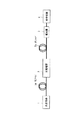
図1は、本発明に係る実施形態の一例を示す光通信システムのブロック図である。
【0014】
本発明に係る光通信システムは、信号光を発生する光送信器1と、信号光を受信する光受信器4と、伝送路を形成する光ファイバ5a、5bにより接続される光送信器1と光受信器4との間に配置され、信号光のパワーを増幅する光増幅器2とを備える。更に、光受信器4の入力側に配置され、信号光の偏波面を検出して、信号光の偏波方向に自動的に偏波方向を合せる偏光器3を備える。なお、図1に示す光通信システムでは、光増幅器2は光中継器として用いられている。
【0015】
光送信機1では、ファブリ−ペローレーザ(FP−LD)や分布帰還型レーザ(DFB−LD)等、適切な信号光源を使用し、この信号光源を信号光に変調して、光ファイバ5aへ伝送する。
【0016】
光受信器4では、光ファイバ5a、5bへ伝送された信号光を、受光器を用いて受光して電気信号へ変換し、その電気信号をデータ信号とクロック信号に出力する。
【0017】
光増幅器2としては、光信号の出力を電気信号に変換することなく光のままで増幅する光増幅器が用いられている。一般的には、半導体増幅器、ファイバラマン散乱増幅器、ファイバブリルアン増幅器、希土類ドープファイバ増幅器等がある。特に、希土類ドープファイバ増幅器の一つであるエルビウムドープファイバ(EDF)増幅器は、偏光依存性がないこと、半導体レーザによる励起が可能であることなどの理由により広く用いられており、信号光の長距離伝送が可能となっている。
【0018】
光信号を増幅する方法として、例えば、EDF増幅器では、光信号を伝送するための媒体である光ファイバにエルビウム(Er)を添加し、このエルビウムドープファイバ(EDF)自体を光増幅器として機能させている。具体的には、半導体レーザ等により、EDFに特定の波長帯の励起光を適切に供給し、更に、EDFに光信号を入力することで、光信号が増幅される。
【0019】
このような光増幅器では、増幅作用時に、信号光だけでなく、信号光の波長を略中心として広い波長範囲に、自然放出増幅光(ASE)と呼ばれる光が出力される。このASEが信号光の伝送特性を劣化させる要因となる。
【0020】
そこで本発明に係る光通信システムでは、光受信器4の入力側に、ASEを除去できるように偏光器3を備えた。偏光器3は、光信号の偏波面を検出し、信号光の偏波方向と偏光器3の偏波方向とを自動的に合わせる機能を有している。偏光器3の具体的な構成の一例としては、信号光の入力側に配置され、信号光の偏波方向を変更(回転)させる偏波回転子と、偏波回転子からの信号光の伝播方向に配置され、所定の偏波方向の信号光を透過させる偏光子と、偏光子を透過した信号光を出力側と光検出器側に分岐させるカプラと、カプラにより分岐された信号光の強度を検出する光検出器と、光検出器による信号により偏波回転子を制御する制御回路とを備えているものがある。なお、同等の機能を有するものであれば、他の構成の偏光器でもよい。
【0021】
偏波回転素子は制御信号に従い、その制御信号で指定される角度だけ、信号光の偏波を回転する。偏波回転素子としては、例えば、複数の波長板を組み合わせたもの(1/2波長板、1/4波長板等)やファラデー回転子からなるものなどがあるが、同等の機能を有するものであれば他のものでもよい。偏光子は、偏波回転素子からの信号光から、所定の偏波方向の成分を抽出する。偏光子からの信号光はカプラに入力され、そのほとんどの信号光を出力光として出力すると共に、その一部を光検出器に供給する。光検出器は、カプラからの一部の信号光を電気信号に変換する。この光検出器の出力は、偏光子からの信号光のパワーと比例し、制御回路は、光検出器の出力に基づき、光検出器の出力が最大になるように偏波回転素子の偏波回転量を制御する。
【0022】
このような制御を行なうことで、偏光器3は、信号光の偏波方向に関わらず、信号光の偏波方向と偏光器3の偏波方向を自動的に合わせて出力することができる。そのため、偏光器3では、信号光は透過することとなり、信号光と偏波方向が直交するASEは透過することができず、除去されることとなる。なお、偏光器3における信号光のパワー損失は、偏波回転素子、偏光子及びカプラにおける損失のみであり、極めて小さいものとなり、光受信器4の直前に偏光器3を配置しても、光受信器に与える影響はほとんどない。
【0023】
つまり、本発明に係る光通信システムは、従来の光通信システムと比較して、信号光を光受信器4で受信する前に、上述のような偏光器3を備えている点が異なっている。すなわち、偏光器3は信号光の偏波面を検出し、その偏波方向を信号光の偏波方向に自動的に合せるように動作し、信号光のみが、この偏光器3を透過することで、光増幅器2で発生するASE光の各偏波成分のうち、信号光偏波面と直交する成分を除去できることとなる。これにより信号光受信時に、ASE間ビート雑音を小さくでき、伝送特性を改善できる。
【0024】
本発明に係る光通信システムにおいて、光送信器1からは、波長1300nm、信号光パワー0dBm、ビットレート156Mbit/sの信号光が送信される。信号光パワーは光ファイバ5aを伝搬する間に減衰し、光増幅器2への入力信号光パワーは−25dBmとなる。光増幅器2はASEを除去するための光フィルタは装備していない。又、光増幅器は光中継器として使用され、信号光パワーを+10dBmに増幅する。光受信器4の受信感度は−38.9dBm(誤り率10−9)である。このような条件において、信号光の伝送特性を、従来の光通信システムと比較してみた。
【0025】
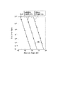
図2は、本発明に係る光通信システムと従来の光通信システムの伝送特性(符号誤り率)の比較を示す図である。
【0026】
図2のグラフ中のB−B(Back to Back)線は、光送信器1を光受信器4へ直接接続した場合の符号誤り率の伝送特性を示すものである。これを基準に、本発明に係る光通信システムと従来の光通信システムの伝送特性を比較してみる。誤り率は光受信器4の光パワー入力端に光可変アッテネータを配置し、光受信器4の入力光パワーを変化させながら測定した。誤り率10−9の場合、従来の光通信システムではパワーペナルティ3.8dBであったのに対して、本発明の光通信システムではパワーペナルティは1.8dBで2.0dBの伝送特性改善があった。なお、パワーペナルティとは、受信感度の劣化を実質的な受信パワーの損失として見積もった量である。
【0027】
なお、本実施例では、信号光波長を1300nmとしたが、信号光波長はこれに限定されるものではない。又、本実施例では偏光器3を光受信器の光パワー入力端に配置しているが、光増幅器2の出力端に配置しても良い。
【0028】
更に、光増幅器を前置増幅器(プリアンプ)として使用した場合にも、同様にパワーペナルティの減少の効果が得られた。図3は、光増幅器を前置増幅器として使用した光通信システムであり、本発明に係る実施形態の他の一例を示すブロック図である。
【0029】
図3に示す本発明に係る光通信システムは、前述の実施例の光通信システムと略同等の構成であるため、重複する説明は省略するが、本実施例の光通信システムでは、光受信器4の前に前置増幅器としての光増幅器2を配置し、光受信器4と光増幅器2の間に偏光器3を配置したことが特徴である。いずれの実施例にしても、光受信器4の入力側に偏光器3を配置して、光増幅器3からのASEの影響を排除するようにしている。
【0030】
図1、図3に示す実施例の光通信システムにおいて使用されている光増幅器は、いずれもASE除去用の光フィルタを備えていない。しかしながら、光送信器1の発生する光信号のスペクトルが数nmの範囲にある場合は、それより半値幅の大きい光フィルタを光増幅器2に装備することによりASEの一部を除去でき、パワーペナルティが更に小さくなる。具体的には、ASE除去用(半値幅5nm)の光フィルタを備えた光増幅器2を使用した場合には、パワーペナルティに0.8dBの改善があった。
【0031】
従来は、信号光の波長にあわせて狭帯域のフィルタを用意しなければならず、又、信号光の波長が変わるとその波長に応じた狭帯域フィルタを新たに用意しなければならなかった。しかしながら、本実施例でも明らかなように、本発明の光通信システムを用いれば、上記のフィルタは必要ではなくなり、かつ信号光の波長が異なる光通信システムでも、光増幅に伴うノイズであるASEを簡単に効率よく除去できることができた。更に、複数チャネルの偏波面を揃えることで、複数の波長を同時に使用する(波長多重:WDM)光通信システムにおいても、同等の効果を得ることが可能である。
【0032】
【発明の効果】
以上説明したように、本発明によれば、偏光器が信号光の偏波面を検出し、偏波方向を信号の偏波方向に自動的に合せることにより、信号光受信時のASE光を減らして、ASE間ビート雑音を抑制することができ、光増幅器を光中継器として使用した場合、光フィルタを用いることなく、伝送特性の劣化を抑えることができる。
【図面の簡単な説明】
【図1】本発明に係る実施形態の一例を示す光通信システムのブロック図である。
【図2】本発明に係る光通信システムと従来の光通信システムの伝送特性(符号誤り率)の比較を示す図である。
【図3】本発明に係る実施形態の他の一例を示す光通信システムのブロック図である。
【符号の説明】
1 光送信器
2 光増幅器
3 偏光器
4 光受信器
5 光ファイバ
5a 光ファイバ
5b 光ファイバ[0001]
TECHNICAL FIELD OF THE INVENTION
The present invention relates to an optical communication system for transmitting an optical signal.
[0002]
[Prior art]
In recent years, with the spread of the Internet, demand for high-speed data communication has spread not only to large-scale businesses but also to small businesses and ordinary households. In response to such demands, the introduction of optical communication systems has been progressing not only in trunk networks but also in optical access networks.
[0003]
In an optical access network, a Fabry-Perot laser (FP-LD) that oscillates in multiple modes with a wide spectrum width may be used as a signal light source to simplify the system and reduce costs. In addition, even when a distributed feedback laser (DFB-LD) that oscillates in a single mode is used as a signal light source, a system is constructed so that the laser can be used if the oscillation wavelength is in the range of several nm to several tens of nm.
[0004]
[Non-patent document 1]
Ono et al., "Development of Optical Fiber Amplifier for 1.3 μm Band Optical Access Network", IEICE CS2001-25, 2001.
[0005]
[Problems to be solved by the invention]
In the optical access network, similarly to the trunk network, an optical amplifier is used when the transmission distance is long or the current system is extended.
[0006]
However, in the above-described optical access network, since the oscillation wavelength of the signal light is not specified, it is difficult to provide the optical amplifier with a narrow-band optical filter. When an optical amplifier without an optical filter is used as an optical repeater, spontaneous emission amplified light (ASE) having a wide spectrum width is mixed with the output of the optical amplifier in addition to the amplified signal light. , The output power of the ASE is not small. If signal light is received by an optical receiver in the presence of a strong ASE, transmission characteristics are significantly degraded by noise due to interference between ASEs (beat noise between ASEs). In particular, when the intensity of the optical signal input to the optical amplifier becomes small due to the loss of the optical fiber forming the transmission line, the ASE intensity becomes relatively large as compared with the intensity of the amplified signal light. Is a cause of deterioration.
[0007]
The present invention has been made in view of the above problems, and has as its object to provide an optical communication system that suppresses deterioration of transmission characteristics due to ASE of an optical amplifier without using an optical filter.
[0008]
[Means for Solving the Problems]
An optical communication system according to claim 1 of the present invention that solves the above-mentioned problems includes an optical transmitter that generates signal light, an optical receiver that receives the signal light, and the optical transmitter that is connected by an optical fiber. An optical amplifier disposed between the optical receiver and amplifying the power of the signal light, further detecting a polarization plane of the signal light, and adjusting a polarization direction to a polarization direction of the signal light. A polarizer is provided.
[0009]
An optical communication system according to a second aspect of the present invention that solves the above problem is characterized in that the polarizer is arranged on the input side of the optical receiver.
[0010]
An optical communication system according to a third aspect of the present invention for solving the above-mentioned problems is characterized in that the optical amplifier is an optical repeater or a preamplifier.
[0011]
(Action)
In the above invention, a polarizer is provided on the optical receiving end side of an optical communication system transmission line having an optical amplifier, and the polarizer detects the polarization plane of the signal light, and determines the polarization direction of the signal light and the polarization in the polarizer. By automatically adjusting the wave direction, the ASE whose polarization direction is orthogonal to the signal light cannot pass through the polarizer and is not transmitted to the optical receiver.
[0012]
BEST MODE FOR CARRYING OUT THE INVENTION
The present invention is characterized in that, in an optical communication system, when weak transmitted signal light is amplified by an optical amplifier (optical amplifier), ASE, which is noise, is removed by a polarizer instead of an optical filter. . As a removing method, the polarization direction of the signal light and the polarization direction of the polarizer are automatically adjusted to exclude ASE in which the polarization direction is orthogonal to the signal light. This specific embodiment will be described below.
[0013]
FIG. 1 is a block diagram of an optical communication system showing an example of an embodiment according to the present invention.
[0014]
An optical communication system according to the present invention includes an optical transmitter 1 for generating signal light, an optical receiver 4 for receiving signal light, and an optical transmitter 1 connected by optical fibers 5a and 5b forming a transmission path. An
[0015]
The optical transmitter 1 uses an appropriate signal light source such as a Fabry-Perot laser (FP-LD) or a distributed feedback laser (DFB-LD), modulates this signal light source into a signal light, and transmits the signal light to the optical fiber 5a. I do.
[0016]
The optical receiver 4 receives the signal light transmitted to the optical fibers 5a and 5b using a light receiver, converts the signal light into an electric signal, and outputs the electric signal as a data signal and a clock signal.
[0017]
As the
[0018]
As a method of amplifying an optical signal, for example, in an EDF amplifier, erbium (Er) is added to an optical fiber which is a medium for transmitting an optical signal, and the erbium-doped fiber (EDF) itself functions as an optical amplifier. I have. Specifically, an optical signal is amplified by appropriately supplying pumping light of a specific wavelength band to the EDF by a semiconductor laser or the like and further inputting an optical signal to the EDF.
[0019]
In such an optical amplifier, light called spontaneous emission amplified light (ASE) is output not only in the signal light but also in a wide wavelength range around the wavelength of the signal light during the amplification operation. This ASE becomes a factor of deteriorating the transmission characteristics of the signal light.
[0020]
Therefore, the optical communication system according to the present invention includes the
[0021]
The polarization rotation element rotates the polarization of the signal light by an angle specified by the control signal according to the control signal. The polarization rotator includes, for example, a combination of a plurality of wavelength plates (a half-wave plate, a quarter-wave plate, etc.) and a device composed of a Faraday rotator, but those having the same function. Others may be used. The polarizer extracts a component in a predetermined polarization direction from the signal light from the polarization rotation element. The signal light from the polarizer is input to the coupler, and most of the signal light is output as output light, and a part of the signal light is supplied to the photodetector. The photodetector converts a part of the signal light from the coupler into an electric signal. The output of the photodetector is proportional to the power of the signal light from the polarizer. Based on the output of the photodetector, the control circuit controls the polarization of the polarization rotation element so that the output of the photodetector becomes maximum. Control the amount of rotation.
[0022]
By performing such control, the
[0023]
That is, the optical communication system according to the present invention is different from the conventional optical communication system in that the optical communication system includes the above-described
[0024]
In the optical communication system according to the present invention, the optical transmitter 1 transmits a signal light having a wavelength of 1300 nm, a signal light power of 0 dBm, and a bit rate of 156 Mbit / s. The signal light power attenuates while propagating through the optical fiber 5a, and the input signal light power to the
[0025]
FIG. 2 is a diagram showing a comparison of transmission characteristics (code error rate) between the optical communication system according to the present invention and a conventional optical communication system.
[0026]
The BB (Back to Back) line in the graph of FIG. 2 shows the transmission characteristics of the bit error rate when the optical transmitter 1 is directly connected to the optical receiver 4. Based on this, the transmission characteristics of the optical communication system according to the present invention and the conventional optical communication system will be compared. The error rate was measured while an optical variable attenuator was arranged at the optical power input end of the optical receiver 4 and the input optical power of the optical receiver 4 was changed. In the case of an error rate of 10 −9 , the power penalty of the conventional optical communication system was 3.8 dB, whereas the power penalty of the optical communication system of the present invention was 1.8 dB and the transmission characteristic was improved by 2.0 dB. Was. The power penalty is an amount obtained by estimating the deterioration of the receiving sensitivity as a substantial loss of the receiving power.
[0027]
In this embodiment, the signal light wavelength is 1300 nm, but the signal light wavelength is not limited to this. In this embodiment, the
[0028]
Further, when the optical amplifier was used as a preamplifier, the effect of reducing the power penalty was similarly obtained. FIG. 3 is an optical communication system using an optical amplifier as a preamplifier, and is a block diagram showing another example of the embodiment according to the present invention.
[0029]
The optical communication system according to the present invention shown in FIG. 3 has substantially the same configuration as that of the optical communication system of the above-described embodiment, and a duplicate description will be omitted. 4 is characterized in that an
[0030]
Each of the optical amplifiers used in the optical communication systems of the embodiments shown in FIGS. 1 and 3 does not include an optical filter for removing ASE. However, when the spectrum of the optical signal generated by the optical transmitter 1 is in the range of several nm, a part of the ASE can be removed by providing the
[0031]
Conventionally, a narrow-band filter must be prepared according to the wavelength of the signal light, and when the wavelength of the signal light changes, a new narrow-band filter corresponding to the wavelength has to be prepared. However, as is apparent from the present embodiment, if the optical communication system of the present invention is used, the above filter is not necessary, and even in an optical communication system in which the wavelength of the signal light is different, ASE which is noise accompanying optical amplification is reduced. It could be easily and efficiently removed. Further, by arranging the polarization planes of a plurality of channels, the same effect can be obtained even in an optical communication system using a plurality of wavelengths simultaneously (wavelength multiplexing: WDM).
[0032]
【The invention's effect】
As described above, according to the present invention, the polarizer detects the polarization plane of the signal light and automatically adjusts the polarization direction to the polarization direction of the signal, thereby reducing the ASE light at the time of receiving the signal light. Thus, beat noise between ASEs can be suppressed, and when an optical amplifier is used as an optical repeater, deterioration of transmission characteristics can be suppressed without using an optical filter.
[Brief description of the drawings]
FIG. 1 is a block diagram of an optical communication system showing an example of an embodiment according to the present invention.
FIG. 2 is a diagram showing a comparison of transmission characteristics (code error rate) between the optical communication system according to the present invention and a conventional optical communication system.
FIG. 3 is a block diagram of an optical communication system showing another example of the embodiment according to the present invention.
[Explanation of symbols]
DESCRIPTION OF SYMBOLS 1
Claims (3)
前記信号光の偏波面を検出し、偏波方向を前記信号光の偏波方向に合わせる偏光器を備えたことを特徴とする光通信システム。An optical transmitter that generates signal light, an optical receiver that receives the signal light, and an optical transmitter that is disposed between the optical transmitter and the optical receiver connected by an optical fiber and amplifies the power of the signal light. An optical communication system comprising an optical amplifier
An optical communication system comprising: a polarizer that detects a polarization plane of the signal light and adjusts a polarization direction to a polarization direction of the signal light.
前記偏光器が前記光受信器の入力側に配置されたことを特徴とする光通信システム。The optical communication system according to claim 1,
An optical communication system, wherein the polarizer is arranged on an input side of the optical receiver.
前記光増幅器が光中継器又は前置増幅器であることを特徴とする光通信システム。In the optical communication system according to claim 1 or 2,
An optical communication system, wherein the optical amplifier is an optical repeater or a preamplifier.
Priority Applications (1)
| Application Number | Priority Date | Filing Date | Title |
|---|---|---|---|
| JP2002296979A JP2004135018A (en) | 2002-10-10 | 2002-10-10 | Optical communication system |
Applications Claiming Priority (1)
| Application Number | Priority Date | Filing Date | Title |
|---|---|---|---|
| JP2002296979A JP2004135018A (en) | 2002-10-10 | 2002-10-10 | Optical communication system |
Publications (1)
| Publication Number | Publication Date |
|---|---|
| JP2004135018A true JP2004135018A (en) | 2004-04-30 |
Family
ID=32286799
Family Applications (1)
| Application Number | Title | Priority Date | Filing Date |
|---|---|---|---|
| JP2002296979A Pending JP2004135018A (en) | 2002-10-10 | 2002-10-10 | Optical communication system |
Country Status (1)
| Country | Link |
|---|---|
| JP (1) | JP2004135018A (en) |
-
2002
- 2002-10-10 JP JP2002296979A patent/JP2004135018A/en active Pending
Similar Documents
| Publication | Publication Date | Title |
|---|---|---|
| US6342965B1 (en) | Optical fiber amplifier and dispersion compensating fiber module for optical fiber amplifier | |
| JP4115027B2 (en) | Excitation light generation means, Raman amplifier and optical repeater using the same | |
| Fludger et al. | Pump to signal RIN transfer in Raman fiber amplifiers | |
| JP2002229084A (en) | Raman amplifier and optical transmission system using the same | |
| US6782209B2 (en) | Optical transmission systems including optical amplifiers and methods | |
| KR20090039674A (en) | System and method for implementing a high capacity unrepeatered optical communication system | |
| US6147796A (en) | Method for determining transmission parameters for the data channels of a WDM optical communication system | |
| Mirza et al. | Design of L+ U‐band Erbium‐doped fiber amplifier based on a single S‐band forward pump source | |
| EP1315321B1 (en) | Pump source including polarization scrambling in raman amplified optical WDM systems | |
| JP2002344054A (en) | Optical amplifier and optical transmission system | |
| Iqbal et al. | Performance characterisation of ultra-wideband Raman amplifiers | |
| EP3000195B1 (en) | Adaptive network optimization in an optical communications system | |
| US7233431B2 (en) | Semiconductor optical amplifier based Raman pump | |
| JP2004135018A (en) | Optical communication system | |
| EP1460736A1 (en) | Multiwavelength depolarized raman pumps | |
| JP4205651B2 (en) | Optical repeater | |
| Espindola et al. | Penalty-free 10 Gbit/s single-channel co-pumped distributed Raman amplification using low RIN 14xx nm DFB pump | |
| Strutz et al. | Polarization-maintaining hybrid erbium-Brillouin amplifier for high-power low-noise sources | |
| Rizzelli et al. | Raman cell optimisation for distributed amplification based transmission systems | |
| KR100581081B1 (en) | Optical amplifier having low noise and wide dynamic input range | |
| Ahmad et al. | An enhanced S-band brillouin/erbium fiber laser with an additional EDFA in sub-loop | |
| KR100275780B1 (en) | All-optical-gain-clamped erbium doped fiber amplifier using stimulated brillouin scattering of dispersion compensating | |
| Du et al. | Co-directionally pumped Raman amplification and its application to long-span transmission | |
| Di Pasquale et al. | Advanced bi-directional Raman pumping schemes for long span unrepeated WDM transmission systems | |
| JPH08331059A (en) | Optical transmitter, optical communication system and method for amplifying optical signal |
Legal Events
| Date | Code | Title | Description |
|---|---|---|---|
| A621 | Written request for application examination |
Free format text: JAPANESE INTERMEDIATE CODE: A621 Effective date: 20050118 |
|
| A977 | Report on retrieval |
Free format text: JAPANESE INTERMEDIATE CODE: A971007 Effective date: 20060926 |
|
| A131 | Notification of reasons for refusal |
Free format text: JAPANESE INTERMEDIATE CODE: A131 Effective date: 20061003 |
|
| A521 | Written amendment |
Free format text: JAPANESE INTERMEDIATE CODE: A523 Effective date: 20061130 |
|
| A131 | Notification of reasons for refusal |
Free format text: JAPANESE INTERMEDIATE CODE: A131 Effective date: 20070320 |
|
| A521 | Written amendment |
Free format text: JAPANESE INTERMEDIATE CODE: A523 Effective date: 20070511 |
|
| A131 | Notification of reasons for refusal |
Free format text: JAPANESE INTERMEDIATE CODE: A131 Effective date: 20070724 |
|
| A521 | Written amendment |
Free format text: JAPANESE INTERMEDIATE CODE: A523 Effective date: 20070921 |
|
| A02 | Decision of refusal |
Free format text: JAPANESE INTERMEDIATE CODE: A02 Effective date: 20071023 |