JP2004124394A - Retaining wall structure and construction method thereof - Google Patents
Retaining wall structure and construction method thereof Download PDFInfo
- Publication number
- JP2004124394A JP2004124394A JP2002286113A JP2002286113A JP2004124394A JP 2004124394 A JP2004124394 A JP 2004124394A JP 2002286113 A JP2002286113 A JP 2002286113A JP 2002286113 A JP2002286113 A JP 2002286113A JP 2004124394 A JP2004124394 A JP 2004124394A
- Authority
- JP
- Japan
- Prior art keywords
- wall
- anchor member
- pair
- columns
- retaining wall
- Prior art date
- Legal status (The legal status is an assumption and is not a legal conclusion. Google has not performed a legal analysis and makes no representation as to the accuracy of the status listed.)
- Pending
Links
Images


Landscapes
- Pit Excavations, Shoring, Fill Or Stabilisation Of Slopes (AREA)
Abstract
Description
【0001】
【発明の属する技術分野】
本発明は、擁壁構造及び擁壁構造の施工方法に関する。
【0002】
【従来の技術】
近時、護岸、擁壁等の土木構築物の構築においては、土木構築物用構築材が用いられる傾向にある。その土木構築物用構築材の一つとして、特許文献1に示すように、壁材部と、該壁材部から該壁材部の上下幅と同一の長さをもって後方に延びる延出部と、該延出部に設けられるフランジ状の抵抗力増大部とをコンクリートにより一体的に形成した土木用ブロックを複数用意し、その複数の土木用ブロックを連結線により連結してその各土木用ブロックの壁材部をもって長尺な壁面パネルを構成したものが示されている。
このものを用いれば、複数の土木用ブロックの壁材部をもって長尺な壁面パネルが構成されることから、土木用ブロックを個々に積み上げる場合に比して積み上げ施工回数を減らすことができ、しかも、連結線を各土木用ブロック間で曲げて、壁面パネルを湾曲させることもできることになる。
【0003】
【特許文献1】
特開2001−146726号公報
【0004】
【発明が解決しようとする課題】
しかし、上記土木構築物用構築材における各土木用ブロックは、壁材部だけでなく、後方に延びる延出部、その延出部に設けられる抵抗力増大部をも、重量安定性、移動抵抗力等を確保するために有しており、それらがコンクリートにより一体的に構成されていることから、各土木用ブロック自体は、かなりの重量物となっている。このため、複数の土木用ブロックを連結して壁面パネルを構成することとした場合には、それを用いれば、積み上げ施工回数を減らすことができるものの、積み上げ作業自体が大がかりとなり、さらには、積み上げ時の微調整は手軽には行えないことになる。
特に、土木構築物として擁壁を構築する場合においては、略垂直な擁壁面をもって、その擁壁面の高さを高めなければならないときがあり、そのようなときには、各土木構築物用構築材個々の安定性を高める必要から、延出部を十分に後方に延ばすと共に抵抗力増大部を大きくとらなければならず、それが、一層、積み上げ作業等を困難なものにする。
【0005】
本発明は以上のような事情を勘案してなされたもので、その第1の技術的課題は、略垂直な擁壁面を高い高さをもって形成する場合であっても、容易に構築することができる擁壁構造を提供することにある。
第2の技術的課題は、上記擁壁構造の施工方法を提供することにある。
【0006】
【課題を解決するための手段】
上記第1の技術的課題を達成するために本発明(請求項1の発明)にあっては、
複数の土木用ブロックを連結線により連結した土木構築物用構築材が基礎面上に順次、積み上げられ、該積み上げられた土木構築物用構築材により該土木構築物用構築材の内側に充填される裏込め材料が保持される擁壁構造において、
前記基礎面上に複数の支柱が間隔をあけて立設され、
前記各土木構築物用構築材が、前記複数の土木用ブロックとして複数の独立した板状の壁材を用いることにより、長尺な壁面パネルとされ、
前記各壁面パネルが、前記支柱の前側において該支柱のいずれかに取付けられ、
前記各支柱に、前記裏込め材料内に延びて該裏込め材料と協働して移動抵抗力を付与するアンカー部材がそれぞれ取付けられている構成としてある。この請求項1の発明の好ましい態様としては、請求項2〜8、13の記載の通りとなる。
【0007】
上記第2の技術的課題を達成するために本発明(請求項9の発明)にあっては、
複数の独立した薄板状の壁材を連結線を用いて連結した長尺な壁面パネルと、複数の支柱と、裏込め材料と協働して移動抵抗力を付与するアンカー部材とを用意し、
先ず、前記複数の支柱を施工面上に間隔をあけて立設し、
次に、前記各支柱に前記アンカー部材を後側に延びるようにして取付けると共に、該アンカー部材が移動抵抗力を発揮するように該アンカー部材を裏込め材料をもって埋め込み、
次に、前記長尺な壁面パネルを、前記支柱の前側において順次、積み上げると共に、該各壁面パネルを該支柱のいずれかに取付け、
次に、前記積み上げられた壁面パネルの後側に裏込め材料を充填する、
ことを特徴とする擁壁構造の施工方法とした構成としてある。この請求項9の発明の好ましい態様としては、請求項10〜12の記載の通りとなる。
【0008】
【発明の効果】
請求項1に記載された発明によれば、アンカー部材が裏込め材料と協働して各支柱の起立状態を補強することから、その起立度の高い(垂直度の高い)各支柱に対して沿わせつつ壁面パネルを積み上げると共に、その各壁面パネルを支柱に取付けさえすえば、その各壁面パネルをもって、高さの高い略垂直な擁壁面であっても確実に形成できることになる。
しかも、その擁壁構築に際して、土木構築物用構築材として、複数の独立した板状の壁材を連結線により連結した壁面パネルが用いられ、その壁面パネルには、後方に延びる延出部も、その延出部に設けられる抵抗力増大部も、いずれも有していないことから、重量を格段に低減させて積み上げ作業等を軽減できることができることになる。勿論この場合、個々の壁材を積み上げる場合に比して積み上げ施工回数を減らすことができると共に、連結線を壁材間で曲げて壁面パネルを湾曲させることができることになる。
したがって、略垂直な擁壁面を高い高さをもって形成する場合であっても、容易且つ確実に構築できる擁壁構造を提供できることになる。
【0009】
請求項2に記載された発明によれば、各支柱が、前後方向において対向する一対の対向壁部と、該一対の対向壁部を連結する連結壁部とを有して、内部が該一対の対向壁部間を介して外部に開放される構成とされ、アンカー部材が、支柱から裏込め材料内に延びる軸状部と、該軸状部の先端部に設けられるストッパーパネルとを備え、一対の対向壁部のうち、後側対向壁部に挿通孔が形成され、後側対向壁部の挿通孔にアンカー部材の基端部が挿通され、アンカー部材の基端部に、後側対向壁部を挟持するように一対のナットが螺合されていることから、少なくとも、アンカー部材のストッパーパネル部分を裏込め材料によって埋め込めれば、アンカー部材を前後方向にほぼ不動状態(大きな移動抵抗が確保された状態)にすることができ、その状態で、軸状部の基端部に螺合される一対のナットの螺合状態を調整することにより、各支柱をその下端部を支点として前後方向に起倒動することができ、所望の起立状態(略垂直状態)を簡単且つ確実に得ることができることになる。このため、高さが高く且つ略垂直な擁壁面を確実に形成できることになる。
しかもこの場合、各支柱における側方の一方が外部に開口され、その開口を通じて軸状部の基端部に対するナットの螺合状態をスパナ等を用いて容易に調整できることになる。
【0010】
請求項3に記載された発明によれば、一対の対向壁部のうちの前側対向壁部に挿通孔が形成され、壁面パネルの裏面側に雌ねじ部が形成され、前側対向壁部の後方側から該前側壁部の挿通孔にボルトが挿通され、そのボルトが壁面パネルの雌ねじ部に螺合されていることから、壁面パネル、支柱及びアンカー部材が機械的結合をもって連結されることになり、高い信頼性をもって強度を確保できることになる。
しかもこの場合も、各支柱における側方の一方が外部に開口され、その開口を通じて、ボルトに対してスパナ等により回転力を与えて、そのボルトを壁面パネルの雌ねじ部に螺合できることになり、支柱に対する壁面パネルの取付けを容易にすることができることになる。
【0011】
請求項4に記載された発明によれば、壁面パネルが、雌ねじ部とボルトとの螺合関係を利用して、隣り合う両支柱に跨るようにして取付けられていることから、壁面パネル内を貫通する連結線を、隣り合う支柱を跨ぐ補強材として有効に利用できることになり、擁壁としての強度を効果的に確保しつつ、施工性を向上させることができることになる(壁面パネルを用いることによる積み上げ施工回数の低減)。
【0012】
請求項5に記載された発明によれば、各支柱が、複数の支柱構成部材を上下方向に連結する構成とされていることから、支柱構成部材を、必要に応じて順次、連結することにより、支柱の高さを所望の高さとすることができ、高さの高い擁壁をも簡単に構築できることになる。
しかも、各支柱構成部材にアンカー部材がそれぞれ取付けられていることから、複数の支柱構成部材を連結して用いるとしても、その各支柱構成部材の起立状態をアンカー部材により的確に保持できることになる。
【0013】
請求項6に記載された発明によれば、各支柱構成部材が、前後方向において対向する一対の対向壁部と、該一対の対向壁部を連結する連結壁部とを有して、外部に開口する凹所が形成される構成とされ、各アンカー部材が、支柱構成部材から裏込め材料内に延びる軸状部と、該軸状部の先端部に設けられるストッパーパネルとを備え、各支柱構成部材に、一対の対向壁部の後側対向壁部において挿通孔が形成され、各支柱構成部材における後側対向壁部の挿通孔に前記アンカー部材の基端部がそれぞれ挿通され、各アンカー部材の基端部に、前記後側対向壁部を挟持するように一対のナットが螺合されていることから、支柱として、複数の支柱構成部材が連結されてなるものを用いる場合であっても、前記請求項2と同様の作用効果を得ることができることになる。
【0014】
請求項7に記載された発明によれば、各支柱構成部材に、一対の対向壁部の前側対向壁部において挿通孔が形成され、壁面パネルの裏面側に雌ねじ部が形成され、各支柱構成部材における前側対向壁部の後方側から該前側壁部の挿通孔にボルトがそれぞれ挿通され、ボルトが前記壁面パネルの雌ねじ部に螺合されていることから、支柱として、複数の支柱構成部材が連結されてなるものを用いる場合であっても、前記請求項3と同様の作用効果を得ることができることになる。
【0015】
請求項8に記載された発明によれば、積み上げられた壁面パネルのうち、上下に隣り合う壁面パネルが凹凸嵌合されていることから、その凹凸嵌合に基づき、各壁面パネルが他の壁面パネルとの関係で支柱から離れる方向の移動が規制されることになり、擁壁としての強度を一層、高めることができることになる。
【0016】
請求項9に記載された発明によれば、先ず、複数の支柱を施工面上に間隔をあけて立設し、次に、各支柱にアンカー部材を後側に延びるようにして取付けると共に、該アンカー部材が移動抵抗力を発揮するように該アンカー部材を裏込め材料をもって埋め込み、次に、長尺な壁面パネルを、支柱の前側において順次、積み上げると共に、該各壁面パネルを該支柱のいずれかに取付け、次に、積み上げられた壁面パネルの後側に裏込め材料を充填することから、前記請求項1に係る擁壁構造を具体的に施工することができることになる。
また、支柱に対する壁面パネルの取付け前に、アンカー部材が移動抵抗力を発揮するように該アンカー部材が裏込め材料をもって埋め込まれることから、該アンカー部材により支柱の起立状態が補強されることになり、調整作業を減らして施工を容易にできるばかりか、略垂直な擁壁面を有する擁壁構造を確実に施工できることになる。
【0017】
請求項10に記載された発明によれば、アンカー部材を、各支柱に該各支柱の下側から上側に間隔をあけて順次、取付けることとし、その支柱に対する各アンカー部材の取付けの度に、そのアンカー部材の取付け後において、裏込め材料によるアンカー部材の埋め込み、壁面パネルの積み上げ及び積み上げられた壁面パネルの後側への裏込め材料の充填を一連の作業として、行うことから、各アンカー部材により、各支柱を常に的確な起立状態に維持することを高めることができることになり、一層、略垂直な擁壁面を有する擁壁構造を容易且つ確実に施工できることになる。
【0018】
請求項11に記載された発明によれば、支柱に対するアンカー部材の取付け構造を、該アンカー部材の基端部を該支柱の構成部を貫通させると共に該構成部を該アンカー部材の基端部に螺合される一対のナットにより挟持するものとし、一連の作業のうち、裏込め材料によるアンカー部材の埋め込み後であって壁面パネルの積み上げ前、或いは該壁面パネルの積み上げ後の少なくともいずれか一方の時において、支柱の起立状態を調べて、該支柱の起立状態を前記アンカー部材の基端部に対する前記一対のナットの螺合状態の調整により調整することから、壁面パネルの積み上げ前に各支柱を所望の起立状態にしたり、壁面パネルの積み上げ後(取付け後)において、各支柱を所望の起立状態にしたりすることができることになり、的確に、略垂直な擁壁面を有する擁壁構造を構築できることになる。
【0019】
請求項12に記載された発明によれば、各支柱を、複数の支柱構成部材を上方に順次、連結して延ばし、各支柱構成部材に対して、2本以上のアンカー部材を上下方向に間隔をあけて取付けることから、支柱構成部材を連結することにより各支柱を適宜、長くすることができると共に、そのように支柱構成部材を連結することにより各支柱を長くする場合であっても、各支柱構成部材に取付けられる2本以上のアンカー部材により的確に各支柱を略垂直な起立状態として、略垂直な擁壁面を有する擁壁構造を構築できることになる。
【0020】
請求項13に記載された発明によれば、壁面パネルの壁材間に保水部材が設けられていることから、植物の生育を促進して、擁壁面の緑化を図る上で好ましいものとなる。
【0021】
【発明の実施の形態】
以下、本発明の実施形態について図面に基づいて説明する。
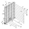
図1〜図4において、符号1は、土木構築物としての擁壁(擁壁構造)で、この擁壁1は、基礎構造体2と、該基礎構造体2上に立設される複数の支柱3と、該各支柱3に取付けられるアンカー部材4と、前記複数の支柱3に沿わせつつ積み上げられた状態で該支柱3に取付けられる壁面パネル5とにより概略構成されており、この擁壁1により、その擁壁1の後側に充填される裏込め材料6(盛土材料)が保持されることになっている。
【0022】
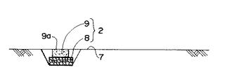
前記基礎構造体2(基礎工)は、図1〜図3に示すように、擁壁形成部分において、その上面が施工面7と略面一になるように形成すべく、砕石層8と、基礎コンクリート9とを備えている。砕石層8は、地中内において、一定の幅(例えば600mm程度)、一定の層厚(例えば200mm前後)をもって延びており、例えば、擁壁面が平坦な場合には、図1に示すように、砕石層8はまっすぐに延び、擁壁面を外に向かって凸となるような曲面とする場合には、砕石層8は、円弧状を形成するように延びることになっている。基礎コンクリート9は、一定の幅(例えば400mm程度)、一定の層厚(例えば200mm前後)をもって砕石層8上に載置された状態で該砕石層8に沿って延びており、この基礎コンクリート9の上面は、施工面と面一な状態をもった基礎面9aとされている。
【0023】
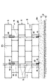
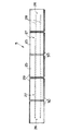
前記複数の支柱3は、図1、図2に示すように、前記基礎コンクリート9の基礎面9a上にその基礎コンクリート9の延び方向において所定間隔毎に設置されている。各支柱3は、図4に示すように、断面が略コ字状とされて、前後方向に対向する一対の対向壁部10と、その一対の対向壁部10を連結する連結壁部11とを備えており、その一対の対向壁部10のうちの一方が前側壁部10a、他方が後側壁部10bとされ、その内部は一対の対向壁部10間を介して外部に開放されることになっている。この場合、各支柱における連結壁部11の下端部がL字状の止金具12を介して基礎コンクリート9の基礎面9aに固定されており、このため、L字状の止金具12の一方の面が基礎コンクリート9の基礎面9aに打ち込みアンカーピン13を用いて固定され、その止金具12の他方の面が支柱の連結壁部11にボルト等14を用いて固定されることになっている。また、この支柱の前側壁部10aには、横方向に延びる壁面パネル用取付け長孔15が上下方向に所定間隔毎に形成され、後側壁部10bには、アンカー用取付け孔16が上下方向に一定間隔毎に形成されている。
【0024】
前記各支柱3は、所定長さ(1〜1.5m前後)の複数の支柱構成部材17を連結することにより構成されている。各支柱構成部材17も、前側壁部10a、後側壁部10b、連結壁部11を備えており、その支柱構成部材17を連結することにより、支柱3として、上下方向に長く延びる前側壁部10a、後側壁部10b、連結壁部11が確保されることになっている。この各支柱構成部材17の連結には、断面コ字状の連結金具18と平板状の当て板19とが用いられており、各支柱構成部材17の端面を互いに合致させるように当接させた状態の下で、連結すべき両支柱構成部材17の連結壁部11が連結金具18と当て板19とにより挟持され、それらがボルト等20を用いて一体的に固定されることになっている。この各支柱構成部材17の前側壁部10aには、前記壁面パネル5用取付け長孔15が、その支柱構成部材17が支える壁面パネル5の積層数に応じた数(例えば4つ)が形成され、各支柱構成部材17の後側壁部10bには、その延び方向両側において前記アンカー用取付け孔16が形成されている(図2,図4参照)。
【0025】
前記各支柱3(各アンカー用取付け孔16)には、図1,図3,図4に示すように、アンカー部材4が取付けられている。アンカー部材4は、軸状部21(例えば亜鉛メッキ処理された鉄筋で1900〜5900mm前後の長さのもの)と、ストッパーパネル22とを備えている。軸状部21は、その両端部に雄ねじ部が形成されており、そのうちの一端部(基端部)は、アンカー用取付け孔16に挿通された状態でその一端部に螺合された一対のナット23a,23bによって後側壁部10bを挟持することになっており、他端側(先端側)は、後側に延びて裏込め材料6(盛土材料)内に埋設されている。ストッパーパネル22は、その板面を軸状部21の延び方向に向けつつ該軸状部21により貫通され、その移動は、本実施形態においては、そのストッパーパネル22の両側において軸状部21の他端部(先端部)に螺合される一対のナット24a,24bにより、不能とされている。これにより、ストッパーパネル22が裏込め材料6と協働して大きな移動抵抗を確保し、アンカー部材4(支柱3)が前後方向(図3中、左右方向)に移動することを規制できることになっている。このストッパーパネル22としては、金属板、プラスチック板等、適宜のものを用いることができる。
【0026】
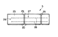
前記複数の壁面パネル5は、図1〜図4に示すように、擁壁面を形成すべく、前記複数の支柱3の前側に配設されている。各壁面パネル5は、複数(本実施形態においては5つ)の独立した壁材としての擬石ブロック25が一列に連結されて長尺なパネル状に形成されており、各擬石ブロック25は、コンクリートを用いて厚板状で且つ長方形状に形成されている(例えば、縦辺:250mm前後、横辺:400mm前後、厚み:100mm前後)。この壁面パネル5には、図5,図6に示すように、その裏面において、2種類の連結孔26,27が形成されている。その2種類の連結孔26,27の内周面には雌ねじ部が形成されており、その各雌ねじ部は、壁面パネル5の製造時にインサートナットを埋め込むことにより形成されている。一方の連結孔26は、壁面パネル5の長手方向端部に位置されて、隣り合う壁面パネル5同士を連結するために用いられるものであり、他方の連結孔27は、壁面パネル5の長手方向において、一方の連結孔26よりもやや内方側に位置されて支柱3に取付けるために用いられるものである。これにより、壁面パネル5の取付けが可能になるだけでなく、壁面パネル5に出っ張り部が存在しないため、壁面パネル5(裏面)を支柱3(支柱構成部材17)に沿わせつつ積み重ねることを容易にできると共に、搬送時に壁面パネル5を積み重ねて搬送することができることになる。
尚、本実施形態においては、上下の壁面パネル5の擬石ブロック25をずらして積層配置する関係上、壁面パネル5の連結孔27の位置を異ならせたもの、図7,図8に示すように壁材ブロック25の数を少なくしたもの等、複数種類のものが用意されている。
【0027】
この各擬石ブロック25は、図5〜図8に示すように、該各擬石ブロック25の横辺が横方向に連続するように配列されており、その全ての擬石ブロック25は、その各擬石ブロック25を横方向に貫通する連結線としての鉄筋28(本実施形態においては、径が10mm前後の2本の鉄筋(鉄線))により、互いに連結されている。この2本の鉄筋28は、上下関係を保つように位置されており、その各鉄筋28は、所定以上の荷重を加えることにより容易に曲げることができるように設定されている。この所定以上の荷重は、各擬石ブロック25の連結強度を確保できることを前提に、曲げ作業性を考慮して適宜決められることになっている。このため、擬石ブロック25間の隙間を考慮にいれつつ、複数の支柱3に沿わせるべく、鉄筋28を各擬石ブロック25間において曲げることによって、壁面パネル54の前面を所望曲率の湾曲面、直角状態等に形成できることになっている。
【0028】
前記壁面パネル54の各擬石ブロック25には、図2,図3〜図5,図7,図8に示すように、その上端面及び下端面において突部29,30が形成されている。擬石ブロック25上端面の突部29は、その厚み方向前側(図3中、左側)において設けられ、擬石ブロック25下端面の突部30は、その厚み方向後側(図3中、右側)において設けられており、壁面パネル5を上下に積層したときに、その両突部29,30の関係により上下の壁面パネル5は、凹凸嵌合ができるようになっている。
【0029】
このような壁面パネル5は、前記複数の支柱3に沿うようにして積み上げられている。すなわち、壁面パネル5は、複数の支柱3が形成する輪郭に沿うように基礎面9a上につなぐように配設されると共に、その上に、次の壁面パネル5が、順次、積み上げられることになっており、その各壁面パネル5は、当接することになる該当支柱3の前側壁部10aに取付けられることになっている。この取付けにおいては、支柱3における前側壁部10aに形成される取付け長孔15にボルト31が挿通され、そのボルト31が壁面パネル5の連結孔27に螺合されて、該当支柱3と壁面パネル5とが一体化(連結)されることになっている。この場合、各壁面パネル5は、基本的に、隣り合う支柱3を跨ぐように配設され、その両支柱3に連結されることになっているが、部分的に壁面の調整を図るために、擬石ブロック25の数が少ない壁面パネル5が使用されることになっている。(図7,8参照)。また、本実施形態においては、各壁面パネル5の長手方向端部が、その壁面パネル5に隣り合う壁面パネル5に連結孔26,連結板32、ボルト等を利用して連結され、さらには、上下の壁面パネル5の上下端面同士が凹凸嵌合されており、各壁面パネル5は強固に一体化されている。
【0030】
前記積み上げられた壁面パネル5の後側には、図3に示すように、吸い出し防止材34を介して裏込め材料6が充填されている。裏込め材料6としては、土等が用いられており、吸い出し防止材34は、各壁面パネル5における壁材ブロック25の間からその土等がこぼれでることを確実に防ぐことになっている。
【0031】
したがって、上記擁壁1においては、アンカー部材4が裏込め材料6と協働して各支柱3の起立状態を補強することから、その起立度の高い(垂直度の高い)各支柱3に対して沿わせつつ壁面パネル5を積み上げると共に、その各壁面パネル5を支柱3に取付けさえすえば、その各壁面パネル5をもって、高さの高い略垂直な擁壁面であっても確実に形成できることになる。
また、この擁壁1においては、土木構築物用構築材が複数の壁材からなる壁面パネル5だけからなり、その壁面パネル5に、後方に延びる延出部も、その延出部に設けられる抵抗力増大部も、いずれも有していないことから、重量を格段に低減させて積み上げ作業等を軽減できることができることになる。勿論この場合、個々の擬石ブロック25を積み上げる場合に比して積み上げ施工回数を減らすことができると共に、連結線28を擬石ブロック25間で曲げて壁面パネル5を湾曲させることができることになる。
【0032】
さらに、アンカー部材4のストッパーパネル22部分を裏込め材料6によって埋め込むことにより、アンカー部材4を前後方向にほぼ不動状態(大きな移動抵抗が確保された状態)にすることができ、その状態で、軸状部21の一端部に螺合される一対のナット23a,23bの螺合状態を調整することにより、各支柱3をその下端部を支点として前後方向に起倒動することができ、所望の起立状態(略垂直状態)を簡単且つ確実に得ることができることになる。
【0033】
さらにまた、壁面パネル5、支柱3及びアンカー部材4が機械的結合をもって連結されることになり、高い信頼性をもって強度を確保できることになる。特に本実施形態においては、壁面パネル5が、基本的に、連結孔とボルトとの螺合関係を利用して、隣り合う両支柱3に跨るようにして取付けられていることから、壁面パネル5内を貫通する連結線28を、隣り合う支柱28を跨ぐ補強材として有効に利用できることになり、擁壁1としての強度を効果的に確保しつつ、施工性を向上させることができることになる(壁面パネル5を用いることによる積み上げ施工回数の低減)。
【0034】
このような擁壁1は、次のようにして施工(構築)される。
先ず、図9に示すように、擁壁を形成すべき施工面7の一部を所定深さまで掘削し、その内部に基礎工を施工し、基礎構造体2を形成する。この場合、基礎構造体2の基礎面9aは、施工面7の他の部分と面一にされ、一定の幅をもって延ばされる。勿論、外に向けて凸となる擁壁面を形成する場合には、基礎面9aは、一定の幅の下で湾曲しつつ延びることになる。
【0035】
次に、図10に示すように、前記基礎面9a上に、複数の支柱構成部材17が間隔をあけて設置される。壁面パネル5を当該支柱構成部材17に沿わせつつ取付けて、略垂直な擁壁面を形成するためである。
この場合、支柱構成部材17間の間隔は、壁面パネル5の長手方向長さを考慮して適宜、決められることになっており、本実施形態においては、壁面パネル5が隣り合う支柱構成部材17間に跨ることができるようにすべく、その間隔は1m前後に設定されている。また、基礎面9aに対する支柱構成部材17の取付けにおいて、L字状の止金具12が用いられるが、この止金具12の一方側を基礎面9aに打ち込みアンカーピン13を用いて固定しておくことにより、他方側が上方に向けて起立することになり、これにより、ボルト等14を用いて簡単に、その他方側に支柱構成部材17における連結壁部11の下端部を沿わせつつ固定できることになる。これに伴い、支柱構成部材17の一対の対向壁部10が前後方向に並ぶことになり、前側壁部10aは、後側壁部10bよりも前側に位置することになる。
【0036】
次に、図11に示すように、各支柱構成部材17の下端部にアンカー部材4が取付けられると共に、基礎面9aの上方部分を除いて、アンカー部材4が裏込め材料6により埋められる。アンカー部材4を利用して、支柱構成部材17の垂直度を調整可能とすると共に、支柱構成部材17の垂直状態を強固に保持するためである。すなわち、アンカー部材4のストッパーパネル22等が裏込め材料6により埋められて該アンカー部材4が前後方向に移動不能となることから、そのアンカー部材4が取付けられた支柱構成部材17は、その起立状態を強固に保持できるが、その起立状態が垂直状態からずれている場合には、アンカー部材4における軸状部21の一端部に螺合される一対のナット23a,23bの螺合状態を調整することにより、支柱構成部材17は、垂直状態に調整される(図11の矢印はナット23a,23bの回転を示す)。この場合、大きな移動抵抗力を確実に確保するために、裏込め材料6はローラ車等により転圧される。
【0037】
次に、図12に示すように、壁面パネル5が複数の支柱構成部材17の前側に沿うように配設されつつ、支柱構成部材17の高さ分だけ、積み上げられると共に、その各壁面パネル5は、当接することになる該当支柱構成部材17に取付けられる。垂直な擁壁を構成するためである。
この場合、支柱構成部材17における前側壁部10aの取付け長孔16からボルト31を通して壁面パネル5の連結孔27に螺合されることになるが、このとき、基礎面9aの上方部分に裏込め材料6が未だ充填されておらず、しかも、支柱構成部材17の内部が外部に開放されてボルト締めが容易に行えることから、各壁面パネル5の取付けを簡単に行うことができることになる。
【0038】
次に、図12に示すように、積み上げられた壁面パネル5の背面に、各支柱構成部材17間において吸い出し防止材34がそれぞれ設けられる。裏込め材料6の流失を確実に防止するためである。
【0039】
次に、図13に示すように、積み上げられた壁面パネル5の後側において、基礎面9a上方部分に裏込め材料6をが充填されて、それがタンパ等により締め固めが行われ、その後、積み上げられた壁面パネル5の近傍付近を除き、次のアンカー部材4の取付け位置まで裏込め材料6が充填される。次のアンカー部材4を支柱構成部材17に取付けるためである。
【0040】
次に、図14に示すように、支柱構成部材17の上端部(アンカー用取付け孔16)に次のアンカー部材4が取付けられると共に、積み上げられた壁面パネル5の近傍付近を除き、そのアンカー部材4が裏込め材料6により埋められる。アンカー部材4を利用して、壁面パネル5が取付けられた支柱構成部材17の垂直度を再度調整可能とすると共に、支柱構成部材17の垂直状態を、一層強固に保持するためである。
【0041】
アンカー部材4による支柱構成部材17の調整を終えると、各支柱構成部材17の上端部に新たな支柱構成部材(図示略)が連結されて、各支柱の長さが上方に延ばされると共に、積み上げられた壁面パネル5の後側において、基礎面9a上方部分に裏込め材料6が充填されて、それがタンパ等により締め固めが行われ、その後、積み上げられた壁面パネル5の近傍付近を除き、さらに次のアンカー部材4の取付けを位置まで裏込め材料6を充填する。そのアンカー部材4を次の支柱構成部材17に取付けるためである。
【0042】
以後、このような作業が繰り返され、図15に示すように所望の高さにおいて、天端コンクリート36が形成されて(天端工)、作業が終了される。
【0043】
したがって、上記施工方法によれば、前記擁壁構造を具体的に施工することができるばかりか、支柱3(支柱構成部材17)に対する壁面パネル5の取付け前に、アンカー部材4が移動抵抗力を発揮するように該アンカー部材4が裏込め材料6をもって埋め込まれることから、該アンカー部材4により支柱の起立状態が補強されることになり、調整作業を減らして施工を容易にでき、さらには、垂直な擁壁面を有する擁壁構造を確実に施工できることになる。
【0044】
また、アンカー部材4を、各支柱構成部材17に該各支柱の下側と上側とに取付けることとし、その支柱3(支柱構成部材17)に対する各アンカー部材4の取付けの度に、そのアンカー部材4の取付け後において、裏込め材料6によるアンカー部材4の埋め込み、壁面パネル5の積み上げ及び積み上げられた壁面パネル5の後側への裏込め材料6の充填を一連の作業として、行うことから、各アンカー部材4により、各支柱3が支柱構成部材17を連結する構成のものでも、常に的確な起立状態に維持することを高めることができることになり、垂直な擁壁面を有する擁壁構造を容易且つ確実に施工できることになる。
【0045】
さらに、一連の作業のうち、裏込め材料6によるアンカー部材4の埋め込み後であって壁面パネル5の積み上げ前、及び壁面パネル5の積み上げ後の時において、支柱3(支柱構成部材17)の起立状態をレベル計等により調べて、該支柱3(支柱構成部材17)の起立状態を前記アンカー部材4の基端部に対する一対のナット23a,23bの螺合状態の調整により調整することから、壁面パネル5の積み上げ前に各支柱3(支柱構成部材17)を所望の起立状態にしたり、壁面パネル5の積み上げ後(取付け後)において、各支柱を所望の起立状態にしたりすることができることになり、的確に、垂直な擁壁面を有する擁壁構造を構築できることになる。勿論、上記調整を、裏込め材料6によるアンカー部材4の埋め込み後であって壁面パネル5の積み上げ前、或いは壁面パネル5の積み上げ後のいずれか一方の時に行ってもよい。
【0046】
図16は他の実施形態を示すものである。この他の実施形態においては、前記実施形態と同一構成要素については同一符号を付してその説明を省略する。
【0047】
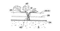
この実施形態においては、壁面パネル5における擬石ブロック25間に保水機能を発揮する保水部材41が保持されている。すなわち、隣り合う擬石ブロック25間の隙間42が、前部半分が前側に向かうに従って横方向に開くように形成されている一方、後部半分が後側に向かうに従って横方向に開くように形成されており、その後部半分の隙間42に保水部材41が嵌め込まれている。この保水部材41としては、例えば、不織布に液状の保水剤を含浸させたもの、袋状のものに顆粒状の保水剤を入れたもの、保水性の繊維であって織布又は不織布であるもの、保水性の高い固形状のブロック形状のもの等が用いられる。
これにより、擬石ブロック25間の隙間42を通じて植物43を生やすことができることになり、擁壁面の緑化を促進することができることになる。勿論この場合、保水部材41は、裏込め材料6からも吸い出し防止材34を経て水分の補給を受けることになる。
【0048】
以上実施形態について説明したが本発明にあっては、次のようなものを包含する。
1)各支柱3(各支柱構成部材17)として、断面略コ字状のものに代えて、断面略エ字状のもの(一対の対向壁部10をその両者の真ん中で連結壁部11により連結した構成のもの)等を用いること。
2)壁面パネル5を支柱3(支柱構成部材17)に取付ける態様として、壁面パネル5の裏面側にボルト等のねじ部材を突設して設け、そのねじ部材を、支柱3における前側壁部の取付け長孔15に挿通し、その挿通されたねじ部材に対してナットを螺合することを含むこと。
3)軸状部21の先端部に対するストッパーパネル22の取付け態様として、軸状部21に留め具を取付けて、ストッパーパネル22の内方側への移動を規制する一方、軸状部21を折り曲げて軸状部21の延び方向外方にストッパーパネル22が移動することを規制する態様、シボ等の拡径部を軸状部21に形成して、ストッパーパネル22の内方側への移動を規制する一方、軸状部21にナットを螺合して軸状部21の延び方向外方にストッパーパネル22が移動することを規制する態様、軸状部21に留め具を取付けて、ストッパーパネル22の内方側への移動を規制する一方、軸状部21にリング状等のカール部を形成して軸状部21の延び方向外方にストッパーパネル22が移動することを規制する態様等を含むこと。
4)支柱構成部材17にアンカー部材を、2本に限らず、3本以上取付けること。
【図面の簡単な説明】
【図1】実施形態に係る擁壁構造を示す斜視図。
【図2】実施形態に係る擁壁構造を後方側から見た図。。
【図3】実施形態に係る擁壁構造を示す縦断面図。
【図4】実施形態に係る擁壁構造を説明する要部拡大図。
【図5】実施形態に係る標準的な壁面パネルを後方側から見た図。
【図6】図5に係る壁面パネルを上方から見た図。
【図7】実施形態に係る他の種類の壁面パネルを後方側から見た図。
【図8】実施形態に係るさらに他の種類の壁面パネルを後方側から見た図。
【図9】実施形態に係る擁壁構造の施工工程を示す図。
【図10】図9の続きの工程を示す図。
【図11】図10の続きの工程を示す図。
【図12】図11の続きの工程を示す図。
【図13】図12の続きの工程を示す図。
【図14】図13の続きの工程を示す図。
【図15】図14の続きの工程を示す図。
【図16】他の実施形態を説明する説明図。
【符号の説明】
1 擁壁
3 支柱
4 アンカー部材
5 壁面パネル
6 裏込め材料
9a 基礎面
10 対向壁部
10a 前側壁部
10b 後側壁部
15 壁面パネル用取付け長孔(挿通孔)
16 アンカー用取付け孔(挿通孔)
17 支柱構成部材
23a ナット
23b ナット
27 連結孔(雌ねじ部)
29 突部
30 突部
31 ボルト
41 保水部材[0001]
TECHNICAL FIELD OF THE INVENTION
The present invention relates to a retaining wall structure and a construction method of the retaining wall structure.
[0002]
[Prior art]
In recent years, in the construction of civil engineering structures such as seawalls and retaining walls, construction materials for civil engineering structures have tended to be used. As one of the construction materials for civil engineering structures, as shown in Patent Document 1, a wall material portion, and an extending portion extending rearward from the wall material portion with the same length as the vertical width of the wall material portion, A plurality of civil engineering blocks in which a flange-shaped resistance increasing portion provided on the extension portion is formed integrally with concrete are prepared, and the plurality of civil engineering blocks are connected by connecting lines to form a plurality of civil engineering blocks. The structure in which a long wall panel is constituted by the wall material portion is shown.
If this is used, since a long wall panel is constituted by the wall material portions of the plurality of civil engineering blocks, the number of times of pile construction can be reduced as compared with the case where the civil engineering blocks are piled individually, and In addition, the connecting lines can be bent between the respective civil engineering blocks, so that the wall panel can be curved.
[0003]
[Patent Document 1]
JP 2001-146726 A
[0004]
[Problems to be solved by the invention]
However, each of the civil engineering blocks in the civil engineering building construction material includes not only the wall material portion but also an extending portion extending rearward, and a resistance increasing portion provided in the extending portion, for weight stability and movement resistance. Each of the blocks for civil engineering itself is quite heavy since they are provided to secure the components and the like and are integrally formed of concrete. For this reason, if a plurality of civil engineering blocks are connected to form a wall panel, the number of times of stacking work can be reduced by using it, but the stacking work itself becomes large and furthermore, Fine adjustment of time cannot be performed easily.
In particular, when a retaining wall is constructed as a civil engineering structure, it may be necessary to increase the height of the retaining wall with a substantially vertical retaining wall. In order to enhance the performance, it is necessary to extend the extending portion sufficiently rearward and increase the resistance increasing portion, which further complicates the stacking operation and the like.
[0005]
The present invention has been made in view of the above circumstances, and the first technical problem is that even if a substantially vertical retaining wall is formed with a high height, it can be easily constructed. It is to provide a retaining wall structure that can be used.
A second technical problem is to provide a construction method of the retaining wall structure.
[0006]
[Means for Solving the Problems]
In order to achieve the first technical problem, the present invention (the invention of claim 1) provides:
Backfill in which building materials for civil engineering structures in which a plurality of civil engineering blocks are connected by connecting lines are sequentially stacked on a base surface, and the piled building materials for civil engineering structures are filled inside the building materials for civil engineering structures. In the retaining wall structure where the material is held,
A plurality of columns are erected at intervals on the foundation surface,
The building material for each civil engineering structure is a long wall panel by using a plurality of independent plate-like wall material as the plurality of civil engineering blocks,
Each of the wall panels is attached to one of the posts on the front side of the post,
An anchor member extending into the backfill material and cooperating with the backfill material to impart a movement resistance is attached to each of the columns. Preferred embodiments of the first aspect of the invention are as described in the second to eighth and thirteenth aspects.
[0007]
In order to achieve the second technical problem, in the present invention (the invention of claim 9),
Prepare a long wall panel that connects a plurality of independent thin plate-shaped wall materials using a connection line, a plurality of columns, and an anchor member that provides movement resistance in cooperation with the backfill material,
First, the plurality of columns are erected at intervals on the construction surface,
Next, the anchor member is attached to each of the columns so as to extend rearward, and the anchor member is embedded with a backfill material so that the anchor member exerts a movement resistance.
Next, the long wall panels are sequentially stacked on the front side of the column, and the respective wall panels are attached to any of the columns,
Next, filling the back side of the stacked wall panels with a backfill material,
The construction method of the retaining wall structure is characterized in that: Preferred embodiments of the invention of
[0008]
【The invention's effect】
According to the first aspect of the present invention, since the anchor member cooperates with the back-filling material to reinforce the upright state of each of the columns, the anchor member has a high uprightness (high verticality) for each of the columns. As long as the wall panels are stacked along the wall and each of the wall panels is attached to the column, it is possible to reliably form each of the wall panels even with a tall, substantially vertical retaining wall.
In addition, when constructing the retaining wall, a wall panel in which a plurality of independent plate-shaped wall members are connected by connecting lines is used as a building material for civil engineering structures, and the wall panel has an extending portion extending rearward, Since neither of the resistance increasing portions provided on the extending portion has any, the weight can be significantly reduced, and the stacking operation and the like can be reduced. Of course, in this case, the number of times of stacking work can be reduced as compared with the case where individual wall materials are stacked, and the connecting line can be bent between the wall materials to bend the wall panel.
Therefore, even when a substantially vertical retaining wall is formed with a high height, a retaining wall structure that can be easily and reliably constructed can be provided.
[0009]
According to the invention described in
Moreover, in this case, one side of each pillar is opened to the outside, and the screwing state of the nut with respect to the base end of the shaft portion can be easily adjusted through the opening using a spanner or the like.
[0010]
According to the invention described in
Moreover, in this case as well, one side of each pillar is opened to the outside, and through the opening, a turning force is applied to the bolt with a spanner or the like, so that the bolt can be screwed into the female screw portion of the wall panel. The mounting of the wall panel to the support can be facilitated.
[0011]
According to the invention described in
[0012]
According to the invention described in
In addition, since the anchor members are respectively attached to the respective strut constituent members, even when a plurality of strut constituent members are connected and used, the standing state of each of the strut constituent members can be properly held by the anchor members.
[0013]
According to the invention described in
[0014]
According to the invention described in
[0015]
According to the invention as set forth in
[0016]
According to the invention described in
In addition, before the wall panel is attached to the column, the anchor member is embedded with the backfill material so that the anchor member exerts a movement resistance, so that the anchor member reinforces the upright state of the column. In addition, the construction can be facilitated by reducing the adjustment work, and the retaining wall structure having the substantially vertical retaining wall can be surely constructed.
[0017]
According to the invention described in
[0018]
According to the invention as set forth in
[0019]
According to the invention as set forth in
[0020]
According to the thirteenth aspect, since the water retention member is provided between the wall materials of the wall panel, it is preferable in promoting the growth of plants and greening the retaining wall.
[0021]
BEST MODE FOR CARRYING OUT THE INVENTION
Hereinafter, embodiments of the present invention will be described with reference to the drawings.
1 to 4, reference numeral 1 denotes a retaining wall (retaining wall structure) serving as an civil engineering structure. The retaining wall 1 includes a
[0022]
As shown in FIG. 1 to FIG. 3, the foundation structure 2 (foundation) has a crushed
[0023]
As shown in FIG. 1 and FIG. 2, the plurality of
[0024]
Each of the
[0025]
As shown in FIGS. 1, 3, and 4, an
[0026]
As shown in FIGS. 1 to 4, the plurality of
In the present embodiment, since the pseudo stone blocks 25 of the upper and
[0027]
As shown in FIGS. 5 to 8, each of the pseudo stone blocks 25 is arranged so that the lateral sides of each of the pseudo stone blocks 25 are continuous in the horizontal direction. Reinforcing bars 28 (in the present embodiment, two reinforcing bars (iron wires) having a diameter of about 10 mm) are connected to each other as connecting wires penetrating through the
[0028]
As shown in FIGS. 2, 3 to 5, 7, and 8, each
[0029]
[0030]
As shown in FIG. 3, the back side of the stacked
[0031]
Therefore, in the retaining wall 1, since the
Further, in the retaining wall 1, the building material for the civil engineering structure is composed of only the
[0032]
Further, by embedding the
[0033]
Furthermore, since the
[0034]
Such a retaining wall 1 is constructed (constructed) as follows.
First, as shown in FIG. 9, a part of the
[0035]
Next, as shown in FIG. 10, a plurality of
In this case, the interval between the
[0036]
Next, as shown in FIG. 11, the
[0037]
Next, as shown in FIG. 12, while the
In this case, the
[0038]
Next, as shown in FIG. 12, on the back surface of the stacked
[0039]
Next, as shown in FIG. 13, on the rear side of the stacked
[0040]
Next, as shown in FIG. 14, the
[0041]
When the adjustment of the
[0042]
Thereafter, such work is repeated, and the
[0043]
Therefore, according to the above-mentioned construction method, not only can the retaining wall structure be concretely constructed, but also the
[0044]
Further, the
[0045]
Further, in a series of operations, after the
[0046]
FIG. 16 shows another embodiment. In other embodiments, the same components as those in the above embodiment are denoted by the same reference numerals, and description thereof will be omitted.
[0047]
In this embodiment, a
Thereby, the
[0048]
Although the embodiments have been described above, the present invention includes the following.
1) Each column 3 (each column component member 17) has a substantially U-shaped cross section instead of a substantially U-shaped cross section (a pair of opposing
2) As a mode for attaching the
3) As a mode of attaching the
4) Attach not only two anchor members but also three or more anchor members to the
[Brief description of the drawings]
FIG. 1 is a perspective view showing a retaining wall structure according to an embodiment.
FIG. 2 is a view of the retaining wall structure according to the embodiment as viewed from the rear side. .
FIG. 3 is a longitudinal sectional view showing a retaining wall structure according to the embodiment.
FIG. 4 is an enlarged view of a main part illustrating a retaining wall structure according to the embodiment.
FIG. 5 is a view of a standard wall panel according to the embodiment as viewed from the rear side.
FIG. 6 is a view of the wall panel according to FIG. 5 as viewed from above.
FIG. 7 is a view of another type of wall panel according to the embodiment as viewed from the rear side.
FIG. 8 is a view of still another type of wall panel according to the embodiment as viewed from the rear side.
FIG. 9 is a view showing a construction process of the retaining wall structure according to the embodiment.
FIG. 10 is a view showing a step that follows the step shown in FIG. 9;
FIG. 11 is a view showing a step that follows the step shown in FIG. 10;
FIG. 12 is a view showing a step that follows the step shown in FIG. 11;
FIG. 13 is a view showing a step that follows the step shown in FIG. 12;
FIG. 14 is a view showing a step that follows the step shown in FIG. 13;
FIG. 15 is a view showing a step that follows the step shown in FIG. 14;
FIG. 16 is an explanatory diagram illustrating another embodiment.
[Explanation of symbols]
1 retaining wall
3 props
4 Anchor member
5 wall panels
6 Backfill material
9a Basic surface
10 Opposing wall
10a Front wall
10b Rear wall
15 Mounting slot for wall panel (insertion hole)
16 Anchor mounting holes (insertion holes)
17 Support member
23a nut
23b nut
27 Connecting hole (Female thread)
29 protrusion
30 protrusion
31 volts
41 Water retention member
Claims (13)
前記基礎面上に複数の支柱が間隔をあけて立設され、
前記各土木構築物用構築材が、前記複数の土木用ブロックとして複数の独立した板状の壁材を用いることにより、長尺な壁面パネルとされ、
前記各壁面パネルが、前記支柱の前側において該支柱のいずれかに取付けられ、
前記各支柱に、前記裏込め材料内に延びて該裏込め材料と協働して移動抵抗力を付与するアンカー部材がそれぞれ取付けられている、
ことを特徴とする擁壁構造。Backfill in which building materials for civil engineering structures in which a plurality of civil engineering blocks are connected by connecting lines are sequentially stacked on a base surface, and the piled building materials for civil engineering structures are filled inside the building materials for civil engineering structures. In the retaining wall structure where the material is held,
A plurality of columns are erected at intervals on the foundation surface,
The building material for each civil engineering structure is a long wall panel by using a plurality of independent plate-like wall material as the plurality of civil engineering blocks,
Each of the wall panels is attached to one of the posts on the front side of the post,
An anchor member extending into the backfill material and cooperating with the backfill material to provide movement resistance is attached to each of the struts.
A retaining wall structure characterized by the following.
前記各支柱が、前後方向において対向する一対の対向壁部と、該一対の対向壁部を連結する連結壁部とを有して、内部が該一対の対向壁部間を介して外部に開放される構成とされ、
前記アンカー部材が、前記支柱から前記裏込め材料内に延びる軸状部と、該軸状部の先端部に設けられるストッパーパネルとを備え、
前記一対の対向壁部のうち、後側対向壁部に挿通孔が形成され、
前記後側対向壁部の挿通孔に前記アンカー部材の基端部が挿通され、
前記アンカー部材の基端部に、前記後側対向壁部を挟持するように一対のナットが螺合されている、
ことを特徴とする擁壁構造。In claim 1,
Each of the columns has a pair of opposing walls facing each other in the front-rear direction and a connecting wall connecting the pair of opposing walls, and the inside is open to the outside through the pair of opposing walls. Configuration,
The anchor member includes a shaft portion extending from the column into the backfill material, and a stopper panel provided at a distal end portion of the shaft portion.
An insertion hole is formed in a rear facing wall portion of the pair of facing wall portions,
The base end of the anchor member is inserted into the insertion hole of the rear facing wall portion,
A pair of nuts is screwed into the base end of the anchor member so as to sandwich the rear facing wall.
A retaining wall structure characterized by the following.
前記一対の対向壁部のうちの前側対向壁部に挿通孔が形成され、
前記壁面パネルの裏面側に雌ねじ部が形成され、
前記前側対向壁部の後方側から該前側壁部の挿通孔にボルトが挿通され、
前記ボルトが前記壁面パネルの雌ねじ部に螺合されている、
ことを特徴とする擁壁構造。In claim 2,
An insertion hole is formed in a front facing wall portion of the pair of facing wall portions,
A female screw portion is formed on the back side of the wall panel,
Bolts are inserted from the rear side of the front facing wall portion into the insertion holes of the front side wall portion,
The bolt is screwed into a female screw portion of the wall panel,
A retaining wall structure characterized by the following.
前記壁面パネルが、前記雌ねじ部と前記ボルトとの螺合関係を利用して、隣り合う両支柱に跨るようにして取付けられている、
ことを特徴とする擁壁構造。In claim 3,
The wall panel is attached so as to straddle both adjacent columns using a screwing relationship between the female screw portion and the bolt,
A retaining wall structure characterized by the following.
前記各支柱が、複数の支柱構成部材を上下方向に連結する構成とされ、
前記各支柱構成部材に前記アンカー部材がそれぞれ取付けられている、
ことを特徴とする擁壁構造。In claim 1,
Each of the struts is configured to connect a plurality of strut components in a vertical direction,
The anchor member is attached to each of the support members,
A retaining wall structure characterized by the following.
前記各支柱構成部材が、前後方向において対向する一対の対向壁部と、該一対の対向壁部を連結する連結壁部とを有して、内部が該一対の対向壁部間を介して外部に開放される構成とされ、
前記各アンカー部材が、前記支柱構成部材から前記裏込め材料内に延びる軸状部と、該軸状部の先端部に設けられるストッパーパネルとを備え、
前記各支柱構成部材に、前記一対の対向壁部の後側対向壁部において挿通孔が形成され、
前記各支柱構成部材における後側対向壁部の挿通孔に前記アンカー部材の基端部がそれぞれ挿通され、
前記各アンカー部材の基端部に、前記後側対向壁部を挟持するように一対のナットが螺合されている、
ことを特徴とする擁壁構造。In claim 5,
Each of the strut components has a pair of opposing walls facing each other in the front-rear direction, and a connecting wall connecting the pair of opposing walls, and the inside is externally interposed between the pair of opposing walls. It is configured to be open to
Each of the anchor members includes a shaft portion extending from the support member to the backfill material, and a stopper panel provided at a distal end portion of the shaft portion.
In each of the strut constituent members, an insertion hole is formed in a rear facing wall portion of the pair of facing wall portions,
A base end portion of the anchor member is inserted into an insertion hole of a rear facing wall portion of each of the support members,
A pair of nuts is screwed into the base end of each of the anchor members so as to sandwich the rear facing wall.
A retaining wall structure characterized by the following.
前記各支柱構成部材に、前記一対の対向壁部の前側対向壁部において挿通孔が形成され、
前記壁面パネルの裏面側に雌ねじ部が形成され、
前記各支柱構成部材における前側対向壁部の後方側から該前側壁部の挿通孔にボルトがそれぞれ挿通され、
前記ボルトが前記壁面パネルの雌ねじ部に螺合されている、
ことを特徴とする擁壁構造。In claim 6,
An insertion hole is formed in each of the strut constituent members at a front facing wall portion of the pair of facing wall portions,
A female screw portion is formed on the back side of the wall panel,
Bolts are respectively inserted into the insertion holes of the front side wall portion from the rear side of the front side opposing wall portion in each of the pillar constituent members,
The bolt is screwed into a female screw portion of the wall panel,
A retaining wall structure characterized by the following.
前記積み上げられた壁面パネルのうち、上下に隣り合う壁面パネルが凹凸嵌合されている、
ことを特徴とする擁壁構造。In claim 1,
Out of the stacked wall panels, vertically adjacent wall panels are unevenly fitted,
A retaining wall structure characterized by the following.
先ず、前記複数の支柱を施工面上に間隔をあけて立設し、
次に、前記各支柱に前記アンカー部材を後側に延びるようにして取付けると共に、該アンカー部材が移動抵抗力を発揮するように該アンカー部材を裏込め材料をもって埋め込み、
次に、前記長尺な壁面パネルを、前記支柱の前側において順次、積み上げると共に、該各壁面パネルを該支柱のいずれかに取付け、
次に、前記積み上げられた壁面パネルの後側に裏込め材料を充填する、
ことを特徴とする擁壁構造の施工方法。Prepare a long wall panel that connects a plurality of independent thin plate-shaped wall materials using a connection line, a plurality of columns, and an anchor member that provides movement resistance in cooperation with the backfill material,
First, the plurality of columns are erected at intervals on the construction surface,
Next, the anchor member is attached to each of the columns so as to extend rearward, and the anchor member is embedded with a backfill material so that the anchor member exerts a movement resistance.
Next, the long wall panels are sequentially stacked on the front side of the column, and the respective wall panels are attached to any of the columns,
Next, filling the back side of the stacked wall panels with a backfill material,
A method for constructing a retaining wall structure, characterized in that:
前記アンカー部材を、前記各支柱に該各支柱の下側から上側に間隔をあけて順次、取付けることとし、
前記支柱に対する前記各アンカー部材の取付けの度に、そのアンカー部材の取付け後において、前記裏込め材料による該アンカー部材の埋め込み、前記壁面パネルの積み上げ及び前記積み上げられた壁面パネルの後側への裏込め材料の充填を一連の作業として、行う、
ことを特徴とする擁壁構造の施工方法。In claim 9,
The anchor member is sequentially attached to each of the columns at intervals from the lower side to the upper side of each column,
Each time the anchor member is attached to the column, after the anchor member is attached, embedding the anchor member with the backfill material, stacking the wall panel, and backing the stacked wall panel to the rear side. Filling the filling material as a series of work,
A method for constructing a retaining wall structure, characterized in that:
前記支柱に対するアンカー部材の取付け構造を、該アンカー部材の基端部を該支柱の構成部を貫通させると共に該構成部を該アンカー部材の基端部に螺合される一対のナットにより挟持するものとし、
前記一連の作業のうち、前記裏込め材料によるアンカー部材の埋め込み後であって前記壁面パネルの積み上げ前、或いは該壁面パネルの積み上げ後の少なくともいずれか一方の時において、前記支柱の起立状態を調べて、該支柱の起立状態を前記アンカー部材の基端部に対する前記一対のナットの螺合状態の調整により調整する、
ことを特徴とする擁壁構造の施工方法。In claim 9,
A structure for attaching an anchor member to the support, wherein a base end of the anchor member is made to penetrate through a constituent part of the support and the constituent part is clamped by a pair of nuts screwed to the base end of the anchor member. age,
During the series of operations, after the embedding of the anchor member by the backfill material and before the stacking of the wall panels, or at least one of after the stacking of the wall panels, the upright state of the columns is examined. Adjusting the upright state of the column by adjusting the screwed state of the pair of nuts with the base end of the anchor member;
A method for constructing a retaining wall structure, characterized in that:
前記各支柱を、複数の支柱構成部材を上方に順次、連結して延ばし、
前記各支柱構成部材に対して、2本以上のアンカー部材を上下方向に間隔をあけて取付ける、
ことを特徴とする擁壁構造の施工方法。In any one of claims 9 to 11,
Each of the supports, a plurality of support components are sequentially connected upward, and extended,
Attach two or more anchor members at an interval in the up-down direction to each of the support members,
A method for constructing a retaining wall structure, characterized in that:
前記壁面パネルの壁材間に保水部材が設けられている、
ことを特徴とする擁壁構造。In claim 1,
A water retention member is provided between wall materials of the wall panel,
A retaining wall structure characterized by the following.
Priority Applications (1)
| Application Number | Priority Date | Filing Date | Title |
|---|---|---|---|
| JP2002286113A JP2004124394A (en) | 2002-09-30 | 2002-09-30 | Retaining wall structure and construction method thereof |
Applications Claiming Priority (1)
| Application Number | Priority Date | Filing Date | Title |
|---|---|---|---|
| JP2002286113A JP2004124394A (en) | 2002-09-30 | 2002-09-30 | Retaining wall structure and construction method thereof |
Publications (1)
| Publication Number | Publication Date |
|---|---|
| JP2004124394A true JP2004124394A (en) | 2004-04-22 |
Family
ID=32279246
Family Applications (1)
| Application Number | Title | Priority Date | Filing Date |
|---|---|---|---|
| JP2002286113A Pending JP2004124394A (en) | 2002-09-30 | 2002-09-30 | Retaining wall structure and construction method thereof |
Country Status (1)
| Country | Link |
|---|---|
| JP (1) | JP2004124394A (en) |
Cited By (2)
| Publication number | Priority date | Publication date | Assignee | Title |
|---|---|---|---|---|
| KR100797766B1 (en) * | 2006-11-18 | 2008-01-24 | 솔렌스(주) | Revetment-block structure using natural stones |
| KR100919921B1 (en) * | 2007-07-05 | 2009-10-07 | 주식회사 스마텍엔지니어링 | Retaining Wall using Panel and Constructing Method thereof |
-
2002
- 2002-09-30 JP JP2002286113A patent/JP2004124394A/en active Pending
Cited By (2)
| Publication number | Priority date | Publication date | Assignee | Title |
|---|---|---|---|---|
| KR100797766B1 (en) * | 2006-11-18 | 2008-01-24 | 솔렌스(주) | Revetment-block structure using natural stones |
| KR100919921B1 (en) * | 2007-07-05 | 2009-10-07 | 주식회사 스마텍엔지니어링 | Retaining Wall using Panel and Constructing Method thereof |
Similar Documents
| Publication | Publication Date | Title |
|---|---|---|
| US4911585A (en) | Wall systems | |
| US6299386B1 (en) | Method and apparatus for a shoring wall | |
| AU2014237379B2 (en) | Precast concrete retaining wall | |
| US4592678A (en) | Modular block retaining wall | |
| CA2841100C (en) | Foundation system for bridges and other structures | |
| US4728225A (en) | Method of rehabilitating a waterfront bulkhead | |
| JPH07229147A (en) | Wall surface structure of reinforced earth structure | |
| US9695558B2 (en) | Foundation system for bridges and other structures | |
| KR20110129657A (en) | Retaining wall using frame structure and method of making retaining wall using thereof | |
| JP4703233B2 (en) | Building foundation reinforcement method and structure | |
| KR20040076713A (en) | Retaining Wall using Permanent Anchor and Pre-Cast Concrete Panel and its Construction Method | |
| JP2006316462A (en) | Block masonry retaining wall using chain, and concrete block for use therein | |
| JP2004100157A (en) | Retaining wall structure and its construction method | |
| KR101822412B1 (en) | Rear reinforcement panel and rear reinforcement panel construction method for lamination | |
| JP2004124394A (en) | Retaining wall structure and construction method thereof | |
| WO2014093344A1 (en) | Foundation system for bridges and other structures | |
| JP2787806B2 (en) | Earth retaining wall | |
| JP2000120081A (en) | Slope footing structure | |
| KR20030052871A (en) | Retaining wall and its construction method of steel panel | |
| KR200194424Y1 (en) | Precast retaining wall using high strength micro pile | |
| US20150078838A1 (en) | Horizontal connection for mechanically stabilized earth walls | |
| JP2523234B2 (en) | Anchor retaining wall | |
| KR102016974B1 (en) | Retaining Wall using Continuous Precast Panels, and Constructing Method therefor | |
| JP2002061278A (en) | Septic tank foundation and method for setting septic tank | |
| JP3923463B2 (en) | Construction method of underground structure and fixing metal fitting used in the construction method |