JP2004123791A - High heat resistant polyethylene microporous membrane - Google Patents
High heat resistant polyethylene microporous membrane Download PDFInfo
- Publication number
- JP2004123791A JP2004123791A JP2002285840A JP2002285840A JP2004123791A JP 2004123791 A JP2004123791 A JP 2004123791A JP 2002285840 A JP2002285840 A JP 2002285840A JP 2002285840 A JP2002285840 A JP 2002285840A JP 2004123791 A JP2004123791 A JP 2004123791A
- Authority
- JP
- Japan
- Prior art keywords
- membrane
- polyethylene
- microporous
- gel
- film
- Prior art date
- Legal status (The legal status is an assumption and is not a legal conclusion. Google has not performed a legal analysis and makes no representation as to the accuracy of the status listed.)
- Granted
Links
Classifications
-
- Y—GENERAL TAGGING OF NEW TECHNOLOGICAL DEVELOPMENTS; GENERAL TAGGING OF CROSS-SECTIONAL TECHNOLOGIES SPANNING OVER SEVERAL SECTIONS OF THE IPC; TECHNICAL SUBJECTS COVERED BY FORMER USPC CROSS-REFERENCE ART COLLECTIONS [XRACs] AND DIGESTS
- Y02—TECHNOLOGIES OR APPLICATIONS FOR MITIGATION OR ADAPTATION AGAINST CLIMATE CHANGE
- Y02E—REDUCTION OF GREENHOUSE GAS [GHG] EMISSIONS, RELATED TO ENERGY GENERATION, TRANSMISSION OR DISTRIBUTION
- Y02E60/00—Enabling technologies; Technologies with a potential or indirect contribution to GHG emissions mitigation
- Y02E60/10—Energy storage using batteries
Landscapes
- Manufacture Of Porous Articles, And Recovery And Treatment Of Waste Products (AREA)
- Cell Separators (AREA)
- Secondary Cells (AREA)
Abstract
Description
【0001】
【発明の属する技術分野】
本発明は電池用セパレーターに適したポリエチレン微多孔膜、及びその製造方法に関するものである。
【0002】
【従来の技術】
ポリエチレン微多孔膜は精密濾過膜、電池用セパレーター、コンデンサー用セパレーター、等に使用されている。これらのうち電池用セパレーター、特にリチウムイオン電池用セパレーターとして使用する際には微多孔膜の機械強度や透過性等の一般的特性に加えて、電池内部が過熱した際にセパレーターが溶融して電極を覆う皮膜となり、電流を遮断する事によって電池の安全性を確保するという「ヒューズ効果」が求められている。
【0003】
ポリエチレン微多孔膜の場合には、ヒューズ効果が発現する温度すなわちヒューズ温度は概ね130〜150℃であることが知られており、何らかの理由で電池内部が過熱してもヒューズ温度に達した時点で前記微多孔膜が溶融して電極を皮膜となって覆うので電流が遮断され、電池反応が停止する。ところが温度上昇が極めて急激な場合には、ヒューズ後もさらに電池温度が上昇するために前記皮膜が破れて電流が復帰(ショート)し、電池の安全性を維持することが困難となる。したがって、このような過酷な条件下でも電池の安全性を維持できるような高い耐熱性を持ったポリエチレン微多孔膜の開発が課題とされていた。高い耐熱性を付与する手段として、ポリエチレン微多孔膜を架橋することによって溶融時の機械強度を向上させる方法が開示されている。
【0004】
特許文献1には、ポリオレフィン製のシートを架橋した後に、ポリオレフィンの良溶媒に浸漬してシートを膨潤させ、収縮を防止するか延伸することによって微多孔膜を製造する方法が開示されている。かかる方法では、シートを架橋してから膨潤するため、高いゲル分率のシートを膨潤することが不可能となり、ゲル分率70wt%以上の高い耐熱性を有する微多孔膜が得られないという本質的な問題点があった。また架橋後に膨潤、延伸する工程は、架橋で固定された分子鎖を無理矢理に引き延ばすこととなり、微多孔膜を融点付近の温度に保った場合、引き延ばされた分子鎖が架橋前の状態に戻ろうとするために大きな収縮応力が発生し熱収縮が大きくなるという問題があった。
【0005】
また、特許文献2には、ポリオレフィン製のシートを作成した後、第1の製法ではポリオレフィン製シートを架橋した後に延伸して得られたフィルムを、ポリオレフィンの良溶媒に浸漬してフィルムを膨潤させることによってポリオレフィン微多孔膜を得る方法、または第2の製法として、ポリオレフィンシートを延伸して得られるフィルムを架橋した後に、ポリオレフィンの良溶媒に浸漬してフィルムを膨潤させることによってポリオレフィン微多孔膜を得る方法が開示されている。かかる発明の第1の製法では架橋したシートを延伸しているため、引き延ばされた分子鎖が架橋前の状態に戻る収縮応力が働き、良溶媒で膨潤する時に破膜しやすくなり、微多孔膜としても熱収縮が大きくなるという問題点があった。また、第2の製法では延伸した後に架橋しているが、架橋後に膨潤しているために熱収縮が大きくなる。さらに、ゲル分率が高いフィルムは膨潤が不可能となるため、当該技術ではゲル分率70wt%以上の高い耐熱性を有する微多孔膜が得られないという本質的な問題点があった。
【0006】
一方、本出願人は特許文献3、特許文献4において、高強度かつ耐熱性に優れたポリエチレン微多孔膜を提供する方法を開示した。かかる方法によれば、可塑剤を抽出除去した微多孔膜に対して架橋を施しているため、架橋点は分子の収縮を抑える方向に働き、熱収縮が小さくなるという特徴があった。さらにある範囲の孔径を有する膜に対して架橋を施すことで、鋭敏なヒューズ効果をも有していた。一般に電離放射線によって架橋構造を形成した場合、架橋反応しなかった残存ラジカルが分子鎖を切断することによって経時的な微多孔膜の劣化を引き起こすことが知られており、残存ラジカルによる経時的な劣化のない微多孔膜の開発が望まれていた。
【0007】
特許文献5、特許文献6において、可塑剤抽出後の微多孔膜に架橋構造を形成させた後に、100℃以下で窒素または酸素存在下において残存ラジカルが消失するまで放置する方法が開示されている。かかる方法によれば、電子スピン共鳴装置(ESR)の測定限界までラジカルを消失させることができるが、完全なラジカル消失には至っていないため、例えば溶融強度等に経時劣化が生じるという問題点がある。また、ラジカル消失には架橋後の膜を長時間放置する必要があるため生産性が良くないという問題点があった。
【0008】
【特許文献1】
特開平6−329823号公報、
【特許文献2】
特開平7−70354号公報、
【特許文献3】
WO96/27633号公報、
【特許文献4】
特開平10−7831号公報、
【特許文献5】
特開平11−302434号公報、
【特許文献6】
特開平11−302435号公報
【0009】
【発明が解決しようとする課題】
本発明の課題は上述の問題点を解決し、残存ラジカルによる経時劣化問題が無く、かつ機械強度、透過性に優れた高耐熱性ポリエチレン微多孔膜、及び生産性に優れた該微多孔膜の製造方法を提供することにある。
【0010】
【課題を解決するための手段】
前記問題を解決するため鋭意研究を重ねた結果、抽出前の膜に対して架橋処理を施し、所定の温度にて加熱処理を施すことにより、驚くべき事に従来技術では不可能であった、機械強度と透過性を低下させることなく経時的な強度劣化を無くすことが可能となることを見出し、本発明をなすに至った。
すなわち、本発明は、
[1] 架橋構造を有し、気孔率が20〜80%、ゲル分率が1%以上、平均孔径が0.001〜0.2μm、溶融突き刺し強度が0.01N以上、溶融突き刺し強度保持率が40%以上であることを特徴とする、高強度かつ耐熱性に優れたポリエチレン微多孔膜、
[2] 収縮残存率が15%以上であることを特徴とする(1)に記載のポリエチレン微多孔膜、
【0011】
[3] 常温突き刺し強度が3N/25μm以上であることを特徴とする(1)又は(2)に記載のポリエチレン微多孔膜、
[4] (1)ゲル状延伸膜を作成する工程、(2)該ゲル状延伸膜に少なくとも1回の架橋処理を施す工程、(3)該架橋処理膜を110℃以上の温度で加熱処理する工程、(4)該加熱処理膜に含まれる可塑剤を抽出除去する工程を有することを特徴とするポリエチレン微多孔膜の製造方法、
[5] 架橋処理が電子線照射であることを特徴とする(4)に記載のポリエチレン微多孔膜の製造方法、
[6] (1)〜(3)のいずれかに記載のポリエチレン微多孔膜を用いた電池用セパレーター、
[7] (6)に記載の電池用セパレーターを用いた電池、
である。
【0012】
【発明の実施の形態】
以下、本発明を詳細に説明する。
まず、本発明のポリエチレン微多孔膜について説明する。
ポリエチレン微多孔膜の膜厚は1〜500μmが好ましく、より好ましくは5〜200μm、さらに好ましくは10〜50μmである。膜厚が1μm未満ではその機械強度が十分ではなく、500μmより大きいと電池の小型軽量化に支障が生じる。
【0013】
ポリエチレン微多孔膜の気孔率は20〜80%であり、好ましくは30〜60%である。気孔率が20〜80%の範囲であれば、十分な透過性と十分な機械強度と有する微多孔膜が得られる。
ポリエチレン微多孔膜の25μm換算透気度は、2000秒/100cc/25μm以下が好ましい。25μm換算透気度とは、JIS P−8117準拠のガーレー式透気度計で得られる値に25(μm)/膜厚(μm)を乗じた値である。25μ換算透気度が2000秒/100cc/25μm以下であれば、電池用セパレーターとして十分な透過性が得られる。
【0014】
ポリエチレン微多孔膜の平均孔径は、後述する測定方法で0.001〜0.2μmであり、好ましくは0.005〜0.1μm、より好ましくは0.01〜0.05μmである。平均孔径が0.001μmより小さいと透過性が充分ではなく、平均孔径が0.2μmより大きいとヒューズ効果が緩慢になる。
架橋構造の確認方法は、特に限定されないが、例えば160℃の溶融状態における引張試験によって、架橋点間分子量を測定することで確認することができる(特許文献4参照)。
【0015】
ポリエチレン微多孔膜のゲル分率は1%以上であり、好ましくは10%以上、より好ましくは20%以上、さらに好ましくは40%以上である。ゲル分率が1%未満は、微多孔膜の溶融時の強度発現の観点から好ましくない。ゲル分率の上限については特に限定はないが、例えば電子線照射による架橋の場合、過度の照射は微多孔膜の強度低下を招く恐れがあるため概ね80%を目安としてその架橋構造をコントロールすることが好ましい。
【0016】
ポリエチレン微多孔膜の溶融突き刺し強度は0.01N以上であり、好ましくは0.1N以上、より好ましくは0.2N以上、さらに好ましくは0.4N以上である。高い耐熱性を発現するために0.01N以上が好ましい。
ポリエチレン微多孔膜の溶融突き刺し強度保持率は、40%以上であることが必要であり、好ましくは60%以上、より好ましくは80%以上、さらに好ましくは90%以上である。経時劣化により、溶融突き刺し強度保持率が40%以下では、電池の使用状況によっては十分な安全性を保つことができない。
【0017】
ポリエチレン微多孔膜の常温突き刺し強度は3N/25μm以上が好ましく、より好ましくは4N/25μm以上、さらに好ましくは4.5N/25μm以上、さらにより好ましくは5N/25μm以上である。常温突き刺し強度が3N/25μm以上であれば脱落した活物質等によってセパレーターが短絡することがない。
ポリエチレン微多孔膜の収縮残存率は15%以上が好ましく、より好ましくは18%以上、さらに好ましくは20%以上、さらにより好ましくは22%以上である。収縮残存率が15%以上であれば、ポリエチレン微多孔膜が溶融した時の収縮が小さくなるため、電池用セパレーターとして使用した場合にショートしにくくなるため電池の安全性向上につながる。
【0018】
次に本発明のポリエチレン微多孔膜の製造方法について説明する。
本発明のポリエチレン微多孔膜の製造方法は、(1)ゲル状延伸膜を作成する工程(以下、ゲル状延伸膜作成工程と称す。)(2)該ゲル状延伸膜に少なくとも1回の架橋処理を施す工程(以下、架橋工程と称す。)、(3)該架橋処理膜を110℃以上の温度で加熱処理する工程(以下、ラジカル失活工程と称す。)、(4)該加熱処理膜に含まれる可塑剤を抽出除去する工程(以下、抽出工程と称す。)に分けることができる。ここで、ゲル状とはポリエチレンと、少なくとも1成分の可塑剤からなる組成物を指している。ゲル状延伸膜とは、ポリエチレンの分子鎖が少なくとも1軸方向に配向した状態にあるゲル状組成物を指す。
【0019】
(ゲル状延伸膜作成工程)
ゲル状延伸膜を作成する方法は特に限定されないが、例えばポリエチレンと可塑剤を溶融混練した後に冷却固化させたシートを少なくとも1軸方向に延伸する方法、またはポリエチレンシートを少なくとも1軸方向に延伸した後、該延伸膜を可塑剤で膨潤させる方法等が利用できる。
使用するポリエチレンはエチレンを主体とした結晶性の重合体である高密度ポリエチレンもしくはエチレンとα−オレフィンとの共重合体が好ましく、さらにこれらにポリプロピレン、中密度ポリエチレン、線状低密度ポリエチレン、低密度ポリエチレン、エチレンプロピレンラバー(EPR)等のポリオレフィンを30wt%以下の割合でブレンドしたものでも差し支えない。
【0020】
ポリエチレンの重量平均分子量は10万以上が好ましく、より好ましくは20万以上1000万以下の範囲である。ブレンドや多段重合等の手段によって使用するポリマーの重量平均分子量を好ましい範囲に調節しても差し支えない。
ゲル状組成物を作成する際に使用する可塑剤とは、ポリエチレンに対して膨潤性のある液体であり、例えば流動パラフィンなどの炭化水素、低級脂肪族アルコール、低級脂肪族ケトン、窒素含有機化合物、エーテル、グリコール、低級脂肪族エステル、シリコンオイルなどであり、これらを単独あるいは組み合わせて使用することができる。
【0021】
(架橋工程)
架橋工程としては、ゲル状延伸膜に対して少なくとも一回の架橋処理を施すことができる。架橋処理の方法としては、紫外線や電子線、ガンマ線に代表される電離放射線照射が挙げられるが、このうち電子線照射による方法が好ましい。
電子線照射を行うときの線量は、1〜200Mradが好ましく、より好ましくは2Mrad〜100Mrad、特に好ましくは5Mrad〜50Mradである。線量が小さすぎると十分な架橋密度が得られず、線量が大きすぎると微多孔膜が劣化して機械強度が低下する場合がある。
【0022】
一般に電子線照射によってポリエチレン微多孔膜に架橋を施す場合、電子線照射時の温度が高いほど架橋効率が高くなり、前記したような劣化、すなわち架橋と同時に起こる分子鎖切断による瞬時強度低下等が少なくなることが知られている。しかしながら、このような高温で照射を行うと劣化ではなくポリエチレン微多孔膜の溶融のために透過性や機械強度が損なわれる事があるため、十分な高温で電子線照射を行うには大きな困難があった。本発明が従来技術と大きく異なる特徴の一つは、気孔を有する通常のポリエチレン微多孔膜ではなく、気孔(あるいはその前駆体構造)が可塑剤等で充填され、かつ、延伸配向された「ゲル状延伸膜」を電子線照射の対象とする点にあり、例えば気孔(あるいはその前駆体構造)を有する通常のポリエチレン微多孔膜では透過性の低下等を誘発するような高温(例えばヒューズ温度近辺やそれ以上の高温)においても前記トレードオフを危惧することなく電子線照射を行うことが可能であり、より高い架橋効率を達成する事が出来る。したがって、従来技術よりも高透過性でかつ高強度なポリエチレン微多孔膜を製造することが可能である。
【0023】
前記観点より、照射時の温度は特に制限されないが、例えば室温以上が好ましく、80℃以上がより好ましく、100℃以上が更に好ましく、110℃以上がより更に好ましい。
照射雰囲気は特に制限されないが、瞬時強度低下を少なくするため例えば酸素濃度100ppm以下の窒素雰囲気で行うことが好ましい。なお、本発明のゲル状延伸膜は気孔(あるいはその前駆体構造)が可塑剤等で充填されているため、ポリエチレン微多孔膜に照射する従来技術と比較して同じ照射雰囲気であっても酸素との接触確率が大幅に低いという利点を有する。
照射時の加速電圧も特に制限されないが、たとえば膜厚30μm程度の微多孔膜に照射を行う場合は、200kV程度の加速電圧で良好に架橋処理を行うことができる。
【0024】
(ラジカル失活工程)
架橋処理後のゲル状延伸膜に残存しているラジカルを失活させるために、架橋処理後のゲル状延伸膜を、少なくとも1軸方向に拘束した状態で加熱処理する。架橋工程と同様に、例えば従来技術においてポリエチレン微多孔膜にあえて高温での加熱処理を行った場合、ポリエチレン微多孔膜の溶融のために透過性や機械強度が損なわれる事があった。一方、本発明はゲル状延伸膜に対して加熱処理を行うために透過性の低下等を危惧することなく十分な高温での加熱処理を行うことが出来る。ただし、本発明は溶融による透過性の低下については効果的に防止するものの、高温での配向緩和による機械強度の低下についてはこの限りではないため、加熱処理の上限温度および時間については機械強度と溶融突き刺し強度保持率を参照しながら調整することが望ましい。
【0025】
加熱処理の温度は、110℃以上で、好ましくは120℃以上、より好ましくは125℃以上、更に好ましくは130℃以上である。より具体的に加熱処理の温度範囲としては、好ましくは120℃以上200℃以下、より好ましくは125℃以上160℃以下である。また、ゲル状延伸膜の架橋工程中にラジカル失活工程を行うことも可能である。
加熱処理の時間は、1秒以上10分以下が好ましく、5秒以上5分以下がより好ましく、10秒以上3分以下が更に好ましく、20秒以上1分以下がより更に好ましい。加熱温度が110℃未満でも10分以上の加熱処理を行うことによってラジカルを失活させることができる場合があるが、10分以上の加熱処理時間は生産性の観点から好ましくない。
【0026】
(抽出工程)
抽出方法としては特に限定されないが、可塑剤としてパラフィン油やジオクチルフタレートを使用する場合には塩化メチレンやメチルエチルケトン(MEK)等の有機溶媒で抽出したあと、得られた微多孔膜のヒューズ温度以下で加熱乾燥することによって除去することができる。また、可塑剤にデカリン等の低沸点化合物を使用する場合は微多孔膜を加熱乾燥するだけで除去することが可能である。いずれの場合も膜の収縮による物性低下を防ぐため、膜を拘束することが好ましい。以上の製法によって得られたポリエチレン微多孔膜は、寸法安定性を高めるため必要に応じて熱処理に供してもよい。
【0027】
以下、本発明を実施の形態に基づいてさらに詳細に説明する。実施例において示す試験方法は次の通りである。
(1)膜厚(μm)
デジタル定圧厚さ測定器(東洋精機製:形式B−1、測定子径φ5mm、測定圧62.4kPa)にて測定した。
(2)気孔率(%)
20cm角のサンプルを微多孔膜から切り取り、その体積と重量を求め、得られた結果から次式を用いて計算した。
気孔率(%)=100×(体積(cm3) −重量(g) /0.95)/体積(cm3)
【0028】
(3)平均孔径(μm)
微多孔膜の透気度測定における空気の流れがクヌーセンの流れに、また微多孔膜の透水度測定における水の流れがポアズイユの流れに従うと仮定して、次式より平均孔径d(μm)を求めた。
d=2ν×(Rliq/Rgas)×(16η/3Ps)×106
ここで、ν:空気の分子速度(m/sec)、Rliq:水の透過速度定数(m3/(m2・sec・Pa))、Rgas:空気の透過速度定数(m3/(m2・sec・Pa))、η:水の粘度(Pa・sec)、Ps:標準圧力(=101325Pa)である。
(4)透気度(秒/100cc/25μm)
JIS P−8117準拠のガーレー式透気度計(東洋精機製:型式G−B2C)で得た値に25(μm)/膜厚(μm)を乗じて求めた。
【0029】
(5)ゲル分率(%)
ASTM D2765に基づき、微多孔膜の沸騰パラキシレン中での12時間可溶分抽出後の重量変化より、抽出前の試料の質量に対する抽出後の残存質量の比として次式により求めた。
ゲル分率(%)=100×残存質量(g)/試料質量(g)
(6)常温突き刺し強度(N)
測定温度25℃において、カトーテック製KES−G5ハンディー圧縮試験器を用いて、針先端の曲率半径0.5mm、突き刺し速度2mm/secの条件で突き刺し試験を行い、最大突き刺し荷重を突き刺し強度(N)とした。突き刺し強度に25(μm)/膜厚(μm)を乗じることによって25μ換算常温突き刺し強度とした。
【0030】
(7)溶融突き刺し強度(N)
ポリエチレン微多孔膜を内径13mm、外径25mmのSUS製ワッシャ2枚の間に挟み込み、周囲をクリップで留めたあとあらかじめ160℃に加熱したシリコンオイル(信越化学工業:KF−96−10CS)中に浸漬し、一分間サンプルを溶融させた後に、シリコンオイル中のサンプルに対して、(5)と同様の方法で溶融突き刺し強度(N)を測定した。溶融突き刺し強度に25(μm)/膜厚(μm)を乗じることによって25μ換算溶融突き刺し強度とした。
(8)溶融突き刺し強度保持率(%)
100気圧での酸素とラジカルとの接触確率が、大気圧に比べて100倍になると仮定して、1000日後の空気中における微多孔膜の経時劣化の指標とした。(高圧空気加速試験)具体的には、耐圧オートクレーブ内に微多孔膜を入れ、圧縮空気で9.8(MPa)に加圧し、25℃で10日間保管した後に、微多孔膜の溶融突き刺し強度を測定した。
【0031】
(9)収縮残存率
内径54mm、外径86mm、厚さ2mmの円形の金枠2枚の間にフッ素ゴム2枚を介して微多孔膜のサンプルを挟み込み、周囲をクリップで固定した。この状態の膜を160℃のシリコンオイル(信越化学工業:KF−96−10CS)に1分間浸漬して熱処理を行い、未架橋部分の配向を除去した。次に金枠の内径に沿ってサンプルを切り出し、改めて160℃のシリコンオイルに1分間浸漬し、このときのサンプルの収縮残存率を、サンプルの長径aと短径bから次式より計算した。
収縮残存率(%)=(ab/542 )×100
(10)吸収線量
電子線照射装置内の照射位置において、フィルム線量計にて測定した線量を被照射試料の吸収線量とした。
【0032】
【実施例1】
重量平均分子量28万の高密度ポリエチレン(密度0.95g/cm3)38.25重量部、重量平均分子量35万のポリエチレン(密度0.92g/cm3)6.75重量部、パラフィン油(松村石油研究所:P350P)55重量部を35mmの2軸押出機を用いて200℃で溶融混練し、ハンガーコートダイから30℃に温度調整した冷却ロール上にキャストして厚さ1800μmのゲル状シートを作成した。このシートを連続式の同時2軸延伸機を用いて7X7倍に延伸することによってゲル状延伸膜を作成した。次に該ゲル状延伸膜を金枠に拘束し、バッチ式の電子線照射装置を用いて加速電圧250kV、25℃にて架橋処理を行ったあと130℃に温調したオーブンに投入して30秒間加熱し、ラジカル失活処理を行った。次に膜を金枠で拘束した状態で塩化メチレンでパラフィン油を抽出除去し、ポリエチレン微多孔膜を作成した。
【0033】
【実施例2】
粘度平均分子量200万の超高分子量ポリエチレン(密度0.94g/cm3)5.5重量部、重量平均分子量が28万の高密度ポリエチレン(密度0.95g/cm3)24.5重量部、パラフィン油(松村石油研究所:P350P)70重量部、ポリエチレン100重量部あたり0.375重量部の酸化防止剤を35mmの二軸押出機を用いて200℃で溶融混練し、ハンガーコートダイから30℃に温度調整した冷却ロール上にキャストして厚さ1200μmのゲル状シートを作成した。このシートを連続式の同時2軸延伸機を用いて7×7倍に延伸することによってゲル状延伸膜を作成した。次に該ゲル状延伸膜を連続式の電子線照射装置を用いて加速電圧120kV、110℃、ライン速度6m/minにて架橋処理を行った。次に連続式のテンター延伸機をもちいて、温度130℃、ライン速度9m/minで30秒間加熱し、ラジカル失活処理を行った後、塩化メチレンでパラフィン油を抽出除去し、ポリエチレン微多孔膜を作成した。
【0034】
【比較例1】
実施例1において架橋処理後にラジカル失活処理を行わずにポリエチレン微多孔膜を作成した。
【0035】
【比較例2】
実施例1と同様の方法でゲル状延伸膜を作成した後、金枠に拘束した状態で塩化メチレンでパラフィン油を抽出除去した後に、バッチ式の電子線照射装置を用いて加速電圧250kV、25℃にて架橋処理を行った。次に金枠に拘束した状態で130℃に温調したオーブンに30秒間投入したところ、膜が溶融して透気性が失われたため気孔率等の物性が測定できなかった。
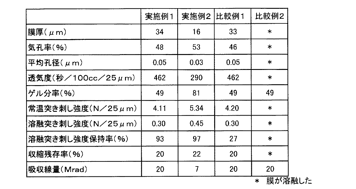
このように作成された微多孔膜を用いて上記の試験方法で試験した結果を表1に示す。
【0036】
【表1】
【発明の効果】
本発明に係るポリエチレン微多孔膜は高い機械強度と耐熱性を有し、かつ残存ラジカルによる経時劣化がまったく無いために、特に電池用セパレーターとして使用する事により従来よりもさらに電池の安全性を高めることが可能となる。[0001]
TECHNICAL FIELD OF THE INVENTION
The present invention relates to a microporous polyethylene membrane suitable for a battery separator and a method for producing the same.
[0002]
[Prior art]
Polyethylene microporous membranes are used for microfiltration membranes, battery separators, condenser separators, and the like. Among them, when used as a battery separator, particularly a lithium ion battery separator, in addition to the general properties such as mechanical strength and permeability of the microporous membrane, when the battery inside is overheated, the separator melts and the electrode There is a demand for a “fuse effect,” which is a film that covers the surface of the battery and that secures the safety of the battery by interrupting the current.
[0003]
In the case of a polyethylene microporous membrane, it is known that the temperature at which the fuse effect appears, that is, the fuse temperature is generally 130 to 150 ° C., and even when the inside of the battery is overheated for some reason, the temperature reaches the fuse temperature. Since the microporous film melts and covers the electrode as a film, the current is interrupted and the battery reaction stops. However, when the temperature rise is extremely rapid, the battery temperature further rises after the fuse, so that the film is broken and the current is restored (short), making it difficult to maintain the safety of the battery. Therefore, development of a microporous polyethylene membrane having high heat resistance capable of maintaining the safety of the battery even under such severe conditions has been an issue. As a means for imparting high heat resistance, there is disclosed a method for improving mechanical strength at the time of melting by crosslinking a microporous polyethylene membrane.
[0004]
Patent Literature 1 discloses a method for producing a microporous membrane by crosslinking a polyolefin sheet and then immersing the sheet in a good solvent for polyolefin to swell the sheet and prevent or shrink the sheet. In this method, since the sheet is crosslinked and then swelled, it is impossible to swell a sheet having a high gel fraction, and a microporous membrane having a high heat resistance with a gel fraction of 70 wt% or more cannot be obtained. Problems. In addition, the process of swelling and stretching after crosslinking involves forcibly stretching the molecular chains fixed by crosslinking, and when the microporous membrane is kept at a temperature near the melting point, the stretched molecular chains are in a state before crosslinking. There is a problem that a large shrinkage stress is generated in order to return, and the heat shrinkage becomes large.
[0005]
Further, in Patent Document 2, after a sheet made of polyolefin is prepared, in a first manufacturing method, a film obtained by stretching after crosslinking a sheet of polyolefin is immersed in a good solvent of polyolefin to swell the film. As a method for obtaining a microporous polyolefin membrane by the above method, or as a second production method, after cross-linking a film obtained by stretching a polyolefin sheet, the polyolefin microporous membrane is immersed in a good solvent of polyolefin to swell the film. A method of obtaining is disclosed. In the first manufacturing method of the invention, since the crosslinked sheet is stretched, a contraction stress is exerted on the stretched molecular chains to return to a state before crosslinking, and the membrane is easily ruptured when swollen with a good solvent. There is a problem that heat shrinkage becomes large even for a porous film. Further, in the second production method, cross-linking is performed after stretching, but heat shrinkage is increased due to swelling after cross-linking. Furthermore, since a film having a high gel fraction cannot swell, there is an essential problem that a microporous film having a high heat resistance with a gel fraction of 70% by weight or more cannot be obtained by this technique.
[0006]
On the other hand, the present applicant has disclosed in Patent Documents 3 and 4 a method for providing a microporous polyethylene membrane having high strength and excellent heat resistance. According to this method, since the microporous membrane from which the plasticizer has been extracted and removed is cross-linked, the cross-linking point acts in the direction of suppressing the shrinkage of the molecule, and the heat shrinkage is reduced. Further, by performing cross-linking on a film having a certain range of pore diameter, a sharp fuse effect was also obtained. In general, when a crosslinked structure is formed by ionizing radiation, it is known that residual radicals that have not undergone a crosslinking reaction cause degradation of the microporous membrane over time by cutting molecular chains, and degradation over time due to residual radicals is known. The development of a microporous membrane without the need has been desired.
[0007]
Patent Literatures 5 and 6 disclose a method in which a crosslinked structure is formed in a microporous membrane after extraction of a plasticizer, and then left at 100 ° C. or lower in the presence of nitrogen or oxygen until residual radicals disappear. . According to such a method, radicals can be eliminated up to the measurement limit of an electron spin resonance apparatus (ESR), but since radicals have not been completely eliminated, there is a problem that, for example, the melt strength or the like deteriorates with time. . In addition, there is a problem that productivity is not good because radical-elimination requires leaving the crosslinked film for a long time.
[0008]
[Patent Document 1]
JP-A-6-329823,
[Patent Document 2]
JP-A-7-70354,
[Patent Document 3]
WO96 / 27633,
[Patent Document 4]
JP-A-10-7831,
[Patent Document 5]
JP-A-11-302434,
[Patent Document 6]
JP-A-11-302435
[Problems to be solved by the invention]
The object of the present invention is to solve the above-mentioned problems, to eliminate the problem of aging due to residual radicals, and to provide a mechanical strength, a highly heat-resistant polyethylene microporous film excellent in permeability, and a microporous film excellent in productivity. It is to provide a manufacturing method.
[0010]
[Means for Solving the Problems]
As a result of intensive studies to solve the above-mentioned problems, the membrane before extraction was subjected to a crosslinking treatment, and by performing a heating treatment at a predetermined temperature, it was surprisingly impossible with the prior art. The present inventors have found that it is possible to eliminate deterioration of strength over time without reducing mechanical strength and permeability, and have accomplished the present invention.
That is, the present invention
[1] It has a crosslinked structure, a porosity of 20 to 80%, a gel fraction of 1% or more, an average pore size of 0.001 to 0.2 μm, a melt piercing strength of 0.01 N or more, and a melt piercing strength retention rate. Is 40% or more, characterized by high strength and excellent heat resistance polyethylene microporous membrane,
[2] The microporous polyethylene membrane according to (1), wherein the residual shrinkage ratio is 15% or more,
[0011]
[3] The microporous polyethylene membrane according to (1) or (2), wherein the piercing strength at room temperature is 3 N / 25 μm or more.
[4] (1) a step of forming a gel-like stretched film, (2) a step of subjecting the gel-like stretched film to at least one cross-linking treatment, and (3) a heat treatment at a temperature of 110 ° C. or more. (4) a method for producing a microporous polyethylene membrane, comprising: a step of extracting and removing a plasticizer contained in the heat-treated membrane;
[5] The method for producing a polyethylene microporous membrane according to (4), wherein the crosslinking treatment is electron beam irradiation.
[6] A battery separator using the polyethylene microporous membrane according to any one of (1) to (3),
[7] A battery using the battery separator according to (6),
It is.
[0012]
BEST MODE FOR CARRYING OUT THE INVENTION
Hereinafter, the present invention will be described in detail.
First, the microporous polyethylene membrane of the present invention will be described.
The thickness of the polyethylene microporous membrane is preferably 1 to 500 µm, more preferably 5 to 200 µm, and still more preferably 10 to 50 µm. If the film thickness is less than 1 μm, the mechanical strength is not sufficient, and if it is more than 500 μm, there is a problem in reducing the size and weight of the battery.
[0013]
The porosity of the polyethylene microporous membrane is 20 to 80%, preferably 30 to 60%. When the porosity is in the range of 20 to 80%, a microporous membrane having sufficient permeability and sufficient mechanical strength can be obtained.
The 25 μm converted air permeability of the polyethylene microporous membrane is preferably 2000 seconds / 100 cc / 25 μm or less. The 25 μm converted air permeability is a value obtained by multiplying a value obtained by a Gurley air permeability meter based on JIS P-8117 by 25 (μm) / film thickness (μm). If the air permeability at 25 μ is 2000 seconds / 100 cc / 25 μm or less, sufficient permeability as a battery separator can be obtained.
[0014]
The average pore size of the polyethylene microporous membrane is 0.001 to 0.2 μm, preferably 0.005 to 0.1 μm, and more preferably 0.01 to 0.05 μm according to the measurement method described below. If the average pore size is smaller than 0.001 μm, the permeability is not sufficient, and if the average pore size is larger than 0.2 μm, the fuse effect becomes slow.
The method for confirming the crosslinked structure is not particularly limited. For example, it can be confirmed by measuring the molecular weight between crosslinking points by a tensile test in a molten state at 160 ° C. (see Patent Document 4).
[0015]
The gel fraction of the polyethylene microporous membrane is 1% or more, preferably 10% or more, more preferably 20% or more, and further preferably 40% or more. If the gel fraction is less than 1%, it is not preferable from the viewpoint of developing strength when the microporous membrane is melted. The upper limit of the gel fraction is not particularly limited. For example, in the case of cross-linking by electron beam irradiation, excessive irradiation may cause a decrease in the strength of the microporous membrane, so that the cross-linked structure is controlled with approximately 80% as a guide. Is preferred.
[0016]
The melt piercing strength of the polyethylene microporous membrane is 0.01 N or more, preferably 0.1 N or more, more preferably 0.2 N or more, and still more preferably 0.4 N or more. 0.01N or more is preferable in order to exhibit high heat resistance.
The retention rate of the melt piercing strength of the microporous polyethylene membrane needs to be 40% or more, preferably 60% or more, more preferably 80% or more, and further preferably 90% or more. If the retention rate of the melt piercing strength is 40% or less due to deterioration with time, sufficient safety cannot be maintained depending on the use condition of the battery.
[0017]
The room-temperature piercing strength of the microporous polyethylene membrane is preferably 3 N / 25 μm or more, more preferably 4 N / 25 μm or more, still more preferably 4.5 N / 25 μm or more, and even more preferably 5 N / 25 μm or more. If the piercing strength at room temperature is 3 N / 25 μm or more, the separator does not short-circuit due to the dropped active material or the like.
The contraction residual rate of the polyethylene microporous membrane is preferably 15% or more, more preferably 18% or more, further preferably 20% or more, and still more preferably 22% or more. When the shrinkage residual ratio is 15% or more, shrinkage when the microporous polyethylene membrane is melted becomes small, and when used as a battery separator, short-circuiting becomes difficult, which leads to improvement in battery safety.
[0018]
Next, the method for producing the microporous polyethylene membrane of the present invention will be described.
The method for producing a polyethylene microporous membrane according to the present invention includes the following steps: (1) a step of forming a gel-like stretched membrane (hereinafter, referred to as a gel-like stretched membrane forming step); and (2) at least one crosslinking of the gel-like stretched membrane. (3) heat-treating the cross-linked film at a temperature of 110 ° C. or higher (hereinafter, referred to as a radical deactivation step); and (4) heating. It can be divided into a step of extracting and removing the plasticizer contained in the membrane (hereinafter, referred to as an extraction step). Here, the gel state refers to a composition comprising polyethylene and at least one plasticizer. The gel-like stretched film refers to a gel-like composition in which polyethylene molecular chains are oriented in at least one axis direction.
[0019]
(Gel-like stretched film making process)
The method for producing the gel-like stretched film is not particularly limited. For example, a method in which a sheet cooled and solidified after melt-kneading polyethylene and a plasticizer is stretched in at least one axial direction, or a polyethylene sheet is stretched in at least one axial direction. Thereafter, a method of swelling the stretched film with a plasticizer can be used.
The polyethylene used is preferably a high-density polyethylene or a copolymer of ethylene and an α-olefin, which is a crystalline polymer mainly composed of ethylene, and further includes polypropylene, medium-density polyethylene, linear low-density polyethylene, and low-density polyethylene. Polyolefins such as polyethylene and ethylene propylene rubber (EPR) may be blended at a ratio of 30 wt% or less.
[0020]
The weight average molecular weight of polyethylene is preferably 100,000 or more, more preferably 200,000 to 10,000,000. The weight average molecular weight of the polymer used may be adjusted to a preferred range by means such as blending or multi-stage polymerization.
The plasticizer used when preparing the gel composition is a liquid having a swelling property with respect to polyethylene, for example, a hydrocarbon such as liquid paraffin, a lower aliphatic alcohol, a lower aliphatic ketone, and a nitrogen-containing organic compound. , Ethers, glycols, lower aliphatic esters, silicone oils and the like, which can be used alone or in combination.
[0021]
(Cross-linking step)
In the crosslinking step, the gel-like stretched film can be subjected to at least one crosslinking treatment. Examples of the method of the crosslinking treatment include irradiation with ionizing radiation typified by ultraviolet rays, electron beams, and gamma rays. Among them, the method using electron beam irradiation is preferable.
The dose for electron beam irradiation is preferably from 1 to 200 Mrad, more preferably from 2 to 100 Mrad, and particularly preferably from 5 to 50 Mrad. If the dose is too small, a sufficient crosslink density cannot be obtained, and if the dose is too large, the microporous membrane may deteriorate and the mechanical strength may decrease.
[0022]
In general, when cross-linking a polyethylene microporous membrane by electron beam irradiation, the higher the temperature at the time of electron beam irradiation, the higher the cross-linking efficiency, and the above-mentioned degradation, that is, instantaneous strength reduction due to molecular chain breakage that occurs simultaneously with cross-linking, etc. It is known to be less. However, if irradiation is performed at such a high temperature, permeability and mechanical strength may be impaired due to melting of the microporous polyethylene film instead of deterioration, so it is very difficult to perform electron beam irradiation at a sufficiently high temperature. there were. One of the features of the present invention that is significantly different from the prior art is that the pores (or their precursor structures) are filled with a plasticizer or the like, and are not stretched, but are stretched and oriented, instead of ordinary polyethylene microporous membranes having pores. The "stretched film" is a target of electron beam irradiation. For example, a normal polyethylene microporous film having pores (or a precursor structure thereof) has a high temperature (for example, near the fuse temperature) that induces a decrease in permeability. Or higher temperature), the electron beam irradiation can be performed without fear of the trade-off, and higher crosslinking efficiency can be achieved. Therefore, it is possible to produce a polyethylene microporous membrane having higher permeability and higher strength than the prior art.
[0023]
From the above viewpoint, the temperature at the time of irradiation is not particularly limited, but is preferably, for example, room temperature or higher, more preferably 80 ° C. or higher, further preferably 100 ° C. or higher, and still more preferably 110 ° C. or higher.
The irradiation atmosphere is not particularly limited, but is preferably performed in a nitrogen atmosphere having an oxygen concentration of 100 ppm or less, for example, in order to reduce the instantaneous strength reduction. Since the pores (or the precursor structure thereof) of the gel-like stretched film of the present invention are filled with a plasticizer or the like, compared with the conventional technology for irradiating a microporous polyethylene film, even if the irradiation atmosphere is the same as that of the conventional technology, the oxygen is reduced. This has the advantage that the probability of contact with is significantly lower.
The acceleration voltage at the time of irradiation is not particularly limited. For example, when irradiation is performed on a microporous film having a film thickness of about 30 μm, the crosslinking treatment can be favorably performed at an acceleration voltage of about 200 kV.
[0024]
(Radical deactivation step)
In order to deactivate the radicals remaining in the gel-like stretched film after the cross-linking treatment, the gel-like stretched film after the cross-linking treatment is heat-treated in a state where it is constrained in at least one axis direction. Similarly to the cross-linking step, for example, in the prior art, if a polyethylene microporous membrane is subjected to heat treatment at a high temperature, the polyethylene microporous membrane may be melted, resulting in impaired permeability and mechanical strength. On the other hand, in the present invention, since the heat treatment is performed on the gel-like stretched film, the heat treatment at a sufficiently high temperature can be performed without fear of a decrease in permeability or the like. However, although the present invention effectively prevents a decrease in permeability due to melting, a decrease in mechanical strength due to relaxation of orientation at high temperatures is not limited to this. It is desirable to adjust while referring to the melt piercing strength retention rate.
[0025]
The temperature of the heat treatment is 110 ° C. or higher, preferably 120 ° C. or higher, more preferably 125 ° C. or higher, and further preferably 130 ° C. or higher. More specifically, the temperature range of the heat treatment is preferably from 120 ° C to 200 ° C, more preferably from 125 ° C to 160 ° C. It is also possible to perform a radical deactivation step during the crosslinking step of the gel-like stretched film.
The time of the heat treatment is preferably from 1 second to 10 minutes, more preferably from 5 seconds to 5 minutes, still more preferably from 10 seconds to 3 minutes, and even more preferably from 20 seconds to 1 minute. Even when the heating temperature is lower than 110 ° C., radicals can be deactivated by performing heat treatment for 10 minutes or more, but a heat treatment time of 10 minutes or more is not preferable from the viewpoint of productivity.
[0026]
(Extraction process)
Although there is no particular limitation on the extraction method, when paraffin oil or dioctyl phthalate is used as a plasticizer, after extraction with an organic solvent such as methylene chloride or methyl ethyl ketone (MEK), the extraction temperature is lower than the fuse temperature of the obtained microporous membrane. It can be removed by heating and drying. When a low boiling compound such as decalin is used as the plasticizer, the microporous membrane can be removed only by heating and drying. In either case, it is preferable to restrain the film in order to prevent a decrease in physical properties due to contraction of the film. The microporous polyethylene membrane obtained by the above-mentioned production method may be subjected to a heat treatment as needed to enhance dimensional stability.
[0027]
Hereinafter, the present invention will be described in more detail based on embodiments. The test method shown in the examples is as follows.
(1) Film thickness (μm)
The thickness was measured with a digital constant-pressure thickness measuring instrument (manufactured by Toyo Seiki Co., Ltd .: Type B-1, measuring element diameter φ5 mm, measuring pressure 62.4 kPa).
(2) Porosity (%)
A sample of 20 cm square was cut out from the microporous membrane, the volume and weight thereof were obtained, and the obtained result was calculated using the following equation.
Porosity (%) = 100 × (volume (cm 3 ) −weight (g) /0.95) / volume (cm 3 )
[0028]
(3) Average pore size (μm)
Assuming that the air flow in the air permeability measurement of the microporous membrane follows the Knudsen flow and the water flow in the water permeability measurement of the microporous membrane follows the Poiseuille flow, the average pore diameter d (μm) is calculated from the following equation. I asked.
d = 2ν × (R liq / R gas ) × (16η / 3P s ) × 10 6
Here, ν: molecular velocity of air (m / sec), R iq : water transmission rate constant (m 3 / (m 2 · sec · Pa)), R gas : air transmission rate constant (m 3 / ( m 2 · sec · Pa)), η: viscosity of water (Pa · sec), P s : standard pressure (= 101325 Pa).
(4) Air permeability (sec / 100cc / 25μm)
It was determined by multiplying the value obtained by a Gurley-type air permeability meter (manufactured by Toyo Seiki: Model G-B2C) based on JIS P-8117 by 25 (μm) / film thickness (μm).
[0029]
(5) Gel fraction (%)
Based on ASTM D2765, the ratio of the residual mass after the extraction to the mass of the sample before the extraction was determined from the weight change of the microporous membrane in the boiling para-xylene after the extraction of the soluble matter for 12 hours, according to the following equation.
Gel fraction (%) = 100 × residual mass (g) / sample mass (g)
(6) Room temperature piercing strength (N)
At a measurement temperature of 25 ° C., a piercing test was performed using a KES-G5 handy compression tester manufactured by Kato Tech under the conditions of a radius of curvature of the needle tip of 0.5 mm and a piercing speed of 2 mm / sec, and the maximum piercing load was punctured (N ). The piercing strength was multiplied by 25 (μm) / film thickness (μm) to obtain a 25 μ converted room temperature piercing strength.
[0030]
(7) Melt piercing strength (N)
A polyethylene microporous membrane is sandwiched between two SUS washers having an inner diameter of 13 mm and an outer diameter of 25 mm, and the periphery thereof is clipped and then heated in 160 ° C. silicon oil (Shin-Etsu Chemical: KF-96-10CS). After the sample was immersed and melted for one minute, the piercing strength (N) of the sample in the silicon oil was measured in the same manner as in (5). By multiplying the melt piercing strength by 25 (μm) / film thickness (μm), the melt piercing strength was converted to 25 μ.
(8) Melt piercing strength retention rate (%)
Assuming that the contact probability between oxygen and radicals at 100 atm is 100 times higher than the atmospheric pressure, it was used as an index of the time-dependent deterioration of the microporous film in air after 1000 days. (High-pressure air acceleration test) Specifically, a microporous membrane was placed in a pressure-resistant autoclave, pressurized to 9.8 (MPa) with compressed air, and stored at 25 ° C for 10 days. Was measured.
[0031]
(9) Residual shrinkage ratio A sample of a microporous membrane was sandwiched between two circular metal frames having an inner diameter of 54 mm, an outer diameter of 86 mm, and a thickness of 2 mm via two fluororubbers, and the periphery thereof was fixed with clips. The film in this state was immersed in silicon oil (Shin-Etsu Chemical: KF-96-10CS) at 160 ° C. for 1 minute to perform a heat treatment to remove the orientation of the uncrosslinked portion. Next, the sample was cut out along the inner diameter of the metal frame, immersed again in silicon oil at 160 ° C. for 1 minute, and the shrinkage residual rate of the sample at this time was calculated from the major axis a and minor axis b of the sample by the following formula.
Shrinkage residual ratio (%) = (ab / 54 2) × 100
(10) Absorbed dose At the irradiation position in the electron beam irradiation device, the dose measured by the film dosimeter was taken as the absorbed dose of the sample to be irradiated.
[0032]
Embodiment 1
High density polyethylene (density 0.95g / cm 3) 38.25 parts by weight of the weight average molecular weight 280,000, polyethylene (density 0.92 g / cm 3) of the weight average molecular weight 350,000 6.75 parts by weight, paraffin oil (Matsumura Petroleum Institute: P350P) 55 parts by weight are melt-kneaded at 200 ° C. using a 35 mm twin-screw extruder, cast from a hanger coat die onto a cooling roll adjusted to 30 ° C., and have a 1800 μm thick gel-like sheet. It was created. This sheet was stretched 7 × 7 times using a continuous simultaneous biaxial stretching machine to prepare a gel-like stretched film. Next, the stretched gel-like film was constrained in a metal frame, subjected to a crosslinking treatment at an acceleration voltage of 250 kV and a temperature of 25 ° C. using a batch-type electron beam irradiation apparatus, and then put into an oven controlled at a temperature of 130 ° C. for 30 minutes. The mixture was heated for 2 seconds to perform a radical deactivation treatment. Next, paraffin oil was extracted and removed with methylene chloride while the membrane was constrained by a metal frame, to produce a microporous polyethylene membrane.
[0033]
Embodiment 2
Ultra high molecular weight polyethylene (density 0.94g / cm 3) 5.5 parts by weight of a viscosity-average molecular weight of 2,000,000, high density polyethylene (density 0.95 g / cm 3) having a weight average molecular weight of 280,000 24.5 parts by weight, 70 parts by weight of paraffin oil (Matsumura Petroleum Institute: P350P), 0.375 parts by weight of antioxidant per 100 parts by weight of polyethylene are melt-kneaded at 200 ° C. using a 35 mm twin screw extruder, and 30 parts from a hanger coat die. It was cast on a cooling roll adjusted to a temperature of ° C to form a gel-like sheet having a thickness of 1200 µm. The sheet was stretched 7 × 7 times using a continuous simultaneous biaxial stretching machine to form a gel stretched film. Next, the gel-like stretched film was subjected to crosslinking treatment at an acceleration voltage of 120 kV, 110 ° C. and a line speed of 6 m / min using a continuous electron beam irradiation apparatus. Next, using a continuous tenter stretching machine, heating was performed at a temperature of 130 ° C. and a line speed of 9 m / min for 30 seconds to perform a radical inactivation treatment, and then paraffin oil was extracted and removed with methylene chloride, and a polyethylene microporous membrane was used. It was created.
[0034]
[Comparative Example 1]
In Example 1, a microporous polyethylene membrane was prepared without performing a radical deactivation treatment after the crosslinking treatment.
[0035]
[Comparative Example 2]
After a gel-like stretched film was prepared in the same manner as in Example 1, paraffin oil was extracted and removed with methylene chloride while being constrained by a metal frame, and then accelerated at a voltage of 250 kV and 25 kV using a batch-type electron beam irradiation apparatus. Crosslinking treatment was carried out at a temperature of ° C. Next, when the film was put into an oven controlled at 130 ° C. for 30 seconds while being restrained by a metal frame, physical properties such as porosity could not be measured because the film was melted and gas permeability was lost.
Table 1 shows the results of a test performed using the microporous membrane thus prepared by the test method described above.
[0036]
[Table 1]
【The invention's effect】
The polyethylene microporous membrane according to the present invention has high mechanical strength and heat resistance, and has no deterioration over time due to residual radicals. It becomes possible.
Claims (7)
Priority Applications (1)
| Application Number | Priority Date | Filing Date | Title |
|---|---|---|---|
| JP2002285840A JP4156894B2 (en) | 2002-09-30 | 2002-09-30 | High heat-resistant polyethylene microporous membrane |
Applications Claiming Priority (1)
| Application Number | Priority Date | Filing Date | Title |
|---|---|---|---|
| JP2002285840A JP4156894B2 (en) | 2002-09-30 | 2002-09-30 | High heat-resistant polyethylene microporous membrane |
Publications (2)
| Publication Number | Publication Date |
|---|---|
| JP2004123791A true JP2004123791A (en) | 2004-04-22 |
| JP4156894B2 JP4156894B2 (en) | 2008-09-24 |
Family
ID=32279041
Family Applications (1)
| Application Number | Title | Priority Date | Filing Date |
|---|---|---|---|
| JP2002285840A Expired - Fee Related JP4156894B2 (en) | 2002-09-30 | 2002-09-30 | High heat-resistant polyethylene microporous membrane |
Country Status (1)
| Country | Link |
|---|---|
| JP (1) | JP4156894B2 (en) |
Cited By (5)
| Publication number | Priority date | Publication date | Assignee | Title |
|---|---|---|---|---|
| JP2007026676A (en) * | 2004-07-21 | 2007-02-01 | Sanyo Electric Co Ltd | Nonaqueous electrolyte battery |
| CN100371057C (en) * | 2006-03-22 | 2008-02-27 | 广东工业大学 | A kind of extraction method for producing polyolefin microporous membrane |
| JP2012502426A (en) * | 2008-09-03 | 2012-01-26 | エルジー・ケム・リミテッド | Separator provided with porous coating layer and electrochemical device provided with the same |
| JP2018181546A (en) * | 2017-04-10 | 2018-11-15 | 旭化成株式会社 | Nonaqueous electrolyte secondary battery separator |
| CN115764170A (en) * | 2015-04-10 | 2023-03-07 | 赛尔格有限责任公司 | Chemically improved microporous separator, rechargeable lithium ion battery, and related methods |
-
2002
- 2002-09-30 JP JP2002285840A patent/JP4156894B2/en not_active Expired - Fee Related
Cited By (7)
| Publication number | Priority date | Publication date | Assignee | Title |
|---|---|---|---|---|
| JP2007026676A (en) * | 2004-07-21 | 2007-02-01 | Sanyo Electric Co Ltd | Nonaqueous electrolyte battery |
| CN100371057C (en) * | 2006-03-22 | 2008-02-27 | 广东工业大学 | A kind of extraction method for producing polyolefin microporous membrane |
| JP2012502426A (en) * | 2008-09-03 | 2012-01-26 | エルジー・ケム・リミテッド | Separator provided with porous coating layer and electrochemical device provided with the same |
| US9142819B2 (en) | 2008-09-03 | 2015-09-22 | Lg Chem, Ltd. | Separator having porous coating layer, and electrochemical device containing the same |
| US9960400B2 (en) | 2008-09-03 | 2018-05-01 | Lg Chem, Ltd. | Separator having porous coating layer, and electrochemical device containing the same |
| CN115764170A (en) * | 2015-04-10 | 2023-03-07 | 赛尔格有限责任公司 | Chemically improved microporous separator, rechargeable lithium ion battery, and related methods |
| JP2018181546A (en) * | 2017-04-10 | 2018-11-15 | 旭化成株式会社 | Nonaqueous electrolyte secondary battery separator |
Also Published As
| Publication number | Publication date |
|---|---|
| JP4156894B2 (en) | 2008-09-24 |
Similar Documents
| Publication | Publication Date | Title |
|---|---|---|
| JP3525390B2 (en) | Polyethylene microporous membrane and manufacturing method | |
| JP5536872B2 (en) | Microporous membranes, methods for producing such membranes, and use of such membranes as battery separator films | |
| JP5220477B2 (en) | Porous film manufacturing method, porous film, nonaqueous electrolyte battery separator, and nonaqueous electrolyte battery using the same | |
| TW553986B (en) | Polyolefin microporous film and method for preparing the same | |
| JP4703076B2 (en) | Microporous film | |
| CN101155861B (en) | Polyolefin microporous membrane and method for producing same | |
| KR101843806B1 (en) | Polyolefin microporous membrane, separator for battery, and battery | |
| JPWO1996027633A1 (en) | Polyethylene microporous membrane and manufacturing method | |
| JP2002128943A (en) | Polyolefin microporous membrane and method for producing the same | |
| JP4606532B2 (en) | Polyolefin microporous membrane | |
| WO2018164057A1 (en) | Microporous polyolefin membrane, multilayer microporous polyolefin membrane, laminated microporous polyolefin membrane and separator | |
| JP4799179B2 (en) | Polyolefin microporous membrane | |
| JP2016191006A (en) | Method for producing polyolefin microporous film, battery separator, and nonaqueous electrolyte secondary battery | |
| JP2001200081A (en) | Polyethylene microporous membrane and method for producing the same | |
| JP3747963B2 (en) | High heat-resistant polyethylene microporous membrane | |
| JP4156894B2 (en) | High heat-resistant polyethylene microporous membrane | |
| JP3400139B2 (en) | Laminated microporous film of olefin polymer, its production method and its use | |
| JP2020164858A (en) | Polyolefin microporous membranes, battery separators, and secondary batteries | |
| JP7771814B2 (en) | Polyolefin microporous membrane, battery separator and secondary battery | |
| JPH1067870A (en) | Polyethylene microporous membrane and manufacturing method | |
| JP4248093B2 (en) | Porous film | |
| JP2017132925A (en) | Heat-resistant synthetic resin microporous film | |
| KR20230160224A (en) | Polyolefin microporous membrane, battery separator and secondary battery | |
| JP4098607B2 (en) | Method for producing polyethylene microporous membrane | |
| JP2003119313A (en) | Method for producing porous film |
Legal Events
| Date | Code | Title | Description |
|---|---|---|---|
| A711 | Notification of change in applicant |
Free format text: JAPANESE INTERMEDIATE CODE: A712 Effective date: 20050228 |
|
| A521 | Request for written amendment filed |
Free format text: JAPANESE INTERMEDIATE CODE: A821 Effective date: 20050301 |
|
| A621 | Written request for application examination |
Free format text: JAPANESE INTERMEDIATE CODE: A621 Effective date: 20050906 |
|
| A977 | Report on retrieval |
Free format text: JAPANESE INTERMEDIATE CODE: A971007 Effective date: 20070919 |
|
| A131 | Notification of reasons for refusal |
Free format text: JAPANESE INTERMEDIATE CODE: A131 Effective date: 20070925 |
|
| A521 | Request for written amendment filed |
Free format text: JAPANESE INTERMEDIATE CODE: A523 Effective date: 20071122 |
|
| A02 | Decision of refusal |
Free format text: JAPANESE INTERMEDIATE CODE: A02 Effective date: 20080115 |
|
| RD03 | Notification of appointment of power of attorney |
Free format text: JAPANESE INTERMEDIATE CODE: A7423 Effective date: 20080214 |
|
| A521 | Request for written amendment filed |
Free format text: JAPANESE INTERMEDIATE CODE: A523 Effective date: 20080314 |
|
| A521 | Request for written amendment filed |
Free format text: JAPANESE INTERMEDIATE CODE: A523 Effective date: 20080425 |
|
| A911 | Transfer to examiner for re-examination before appeal (zenchi) |
Free format text: JAPANESE INTERMEDIATE CODE: A911 Effective date: 20080501 |
|
| TRDD | Decision of grant or rejection written | ||
| A01 | Written decision to grant a patent or to grant a registration (utility model) |
Free format text: JAPANESE INTERMEDIATE CODE: A01 Effective date: 20080703 |
|
| A01 | Written decision to grant a patent or to grant a registration (utility model) |
Free format text: JAPANESE INTERMEDIATE CODE: A01 |
|
| A61 | First payment of annual fees (during grant procedure) |
Free format text: JAPANESE INTERMEDIATE CODE: A61 Effective date: 20080710 |
|
| FPAY | Renewal fee payment (event date is renewal date of database) |
Free format text: PAYMENT UNTIL: 20110718 Year of fee payment: 3 |
|
| R150 | Certificate of patent or registration of utility model |
Free format text: JAPANESE INTERMEDIATE CODE: R150 |
|
| FPAY | Renewal fee payment (event date is renewal date of database) |
Free format text: PAYMENT UNTIL: 20110718 Year of fee payment: 3 |
|
| S111 | Request for change of ownership or part of ownership |
Free format text: JAPANESE INTERMEDIATE CODE: R313111 |
|
| FPAY | Renewal fee payment (event date is renewal date of database) |
Free format text: PAYMENT UNTIL: 20110718 Year of fee payment: 3 |
|
| R350 | Written notification of registration of transfer |
Free format text: JAPANESE INTERMEDIATE CODE: R350 |
|
| FPAY | Renewal fee payment (event date is renewal date of database) |
Free format text: PAYMENT UNTIL: 20110718 Year of fee payment: 3 |
|
| FPAY | Renewal fee payment (event date is renewal date of database) |
Free format text: PAYMENT UNTIL: 20120718 Year of fee payment: 4 |
|
| FPAY | Renewal fee payment (event date is renewal date of database) |
Free format text: PAYMENT UNTIL: 20130718 Year of fee payment: 5 |
|
| S111 | Request for change of ownership or part of ownership |
Free format text: JAPANESE INTERMEDIATE CODE: R313111 |
|
| R350 | Written notification of registration of transfer |
Free format text: JAPANESE INTERMEDIATE CODE: R350 |
|
| LAPS | Cancellation because of no payment of annual fees |