JP2004122158A - Die - Google Patents
Die Download PDFInfo
- Publication number
- JP2004122158A JP2004122158A JP2002288224A JP2002288224A JP2004122158A JP 2004122158 A JP2004122158 A JP 2004122158A JP 2002288224 A JP2002288224 A JP 2002288224A JP 2002288224 A JP2002288224 A JP 2002288224A JP 2004122158 A JP2004122158 A JP 2004122158A
- Authority
- JP
- Japan
- Prior art keywords
- die
- cutting edge
- work
- punch
- die body
- Prior art date
- Legal status (The legal status is an assumption and is not a legal conclusion. Google has not performed a legal analysis and makes no representation as to the accuracy of the status listed.)
- Granted
Links
Images


Landscapes
- Punching Or Piercing (AREA)
- Mounting, Exchange, And Manufacturing Of Dies (AREA)
Abstract
Description
【0001】
【発明の属する技術分野】
本発明はダイ金型、特に刃先が打ち抜き時以外にワークと接触しないようにしたダイ金型に関する。
【0002】
【従来の技術】
従来のパンチプレス、例えばタレットパンチプレスは図8に示す構成を有し、パンチ金型Pが上部タレット96に、ダイ金型Dが下部タレット97にそれぞれ取り付けられ、更にパンチ金型Pの上方には、ラム92が設置されている。
【0003】
この構成により、タレットパンチプレスにワークWが搬入されると、該ワークWをクランプ93で掴んで移動させ、ラム92の直下に位置決めし、該ラム92でパンチ金型Pを打圧すると、該パンチ金型Pは下降し、前記ダイ金型Dとの協働により、ワークWを例えば打抜き加工するようになっている。
【0004】
この場合、ダイ金型Dの本体90には、打抜き加工用の穴91が形成され、図示するように、この穴91の上縁部分が刃先94となってワークWが所定の形状に打抜かれ、発生したカスW1が外部に排出される。
【0005】
【発明が解決しようとする課題】
【0006】
しかし、従来のダイ金型Dにおいては(図9)、切刃部95の刃先94がダイ本体90の上面90Aと同じ高さ位置に設けられ、よく知られているように、ワークWは、この上面90A上に設定された移動基準面であるパスラインPLに沿って移動する。
【0007】
即ち、従来は、刃先94がパスラインPLと同じ高さ位置に設けられている。
【0008】
このため、ワークWが移動すると、該ワークWの下面のゴミやバリが、刃先94に付着し、また、ワークWの下面が刃先94やその周辺を擦る。
【0009】
その結果、刃先94が破損してその寿命が短くなり、また、ワークWの下面に疵が付くことがある。
【0010】
従って、ダイ金型Dの交換頻度が多くなり、また、ワークWの下面に疵が付くことにより、加工されたワークWの製品価値が無くなり、再度加工し直さなければならず、加工効率が低下するなどの種々の弊害がある。
【0011】
本発明の目的は、ダイ金型において、刃先が打ち抜き時以外にワークと接触しないようにすることにより、刃先の寿命を長くし、ワークに疵が付かないようすることにある。
【0012】
【課題を解決するための手段】
上記課題を解決するため、本発明は、
パンチ金型Pと協働してワークWに所定のパンチ加工を施すダイ金型Dにおいて、
切刃部1が、ダイ本体2の上面21より低い位置に設けられていることを特徴とするダイ金型Dという技術的手段を講じている。
【0013】
上記本発明の構成によれば、上面21と同じ高さ位置に設定されたパスラインPL(例えば図2)に沿ってワークWが移動しても、切刃部1が上面21より低い位置に設けられているので、移動するワークWが、切刃部1の刃先18と接触しないようになり、該刃先18の損傷が少なくなり、そのため刃先18の寿命は長くなり、またワークWに疵が付かないようになる。
【0014】
このため、ダイ金型において、刃先が打ち抜き時以外にワークと接触しないようにすることにより、刃先の寿命を長くし、ワークに疵が付かないようすることが可能となる。
【0015】
【発明の実施の形態】
以下、本発明を、実施の形態により添付図面を参照して、説明する。
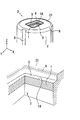
図1は、本発明による第1実施形態を示す斜視図である。
【0016】
図示するダイ金型Dは、よく知られているように、キー溝8、9を介して例えばタレットパンチプレスの(図7(A))下部タレット25に装着され、上部タレット24に装着されたパンチ金型Pと協働してワークWにパンチ加工、例えば打ち抜き加工を施す金型である。
【0017】
図1のダイ金型Dは、ダイ本体2を有し、その上面21中央部に、打抜き用の穴3が開けられ、該穴3の内部には、切刃部1が設けられている。
【0018】
この切刃部1は、ダイ本体2の上面21より低い位置に設けられ、該切刃部1の刃先18の前記上面21に対する深さ位置Hは(図2)、あまりに小さいと、従来どおり、刃先18が、パスラインPLに沿って移動するワークWと接触してしまう。
【0019】
しかし、上記刃先18の深さ位置Hが、あまりに大きいと、後述するパンチ金型P(図7(A))の刃先23と協働してワークWを打ち抜いた場合に(図7(C))、該ワークWが穴3の中に深く入り込んでしまい、弾性限界を越えて元に戻らなくなって打ち抜き穴A(図7(D))の周囲が垂れ下がり、製品としての価値が無くなる。
【0020】
このため、上記切刃部1の刃先18の深さ位置Hは(図2)、ワークWを打ち抜いた場合であって(図7(C))、該ワークWが穴3の中に入り込んだときに、該ワークWが弾性限界内にあり、打ち抜き後は(図7(D))元に戻る程度の適切な深さ位置である。
【0021】
また、切刃部1の刃先18の(図2)周囲には、平坦部5が設けられ、後述するラム22で(図7(A))パンチヘッド32を打圧することにより、パンチ金型P側の刃先23が(図7(C))、該ダイ金型D側の刃先18内に進入した場合に、両刃先23、18によりワークWが打ち抜かれるようになっている。
【0022】
即ち、上記平坦部5が設けられていなければ、切刃部1は、エッジが無くなってしまい、刃先18が有効に作用せず、ワークWは綺麗に打ち抜かれないため、このような平坦部5を設け、パンチ金型P側の刃先23とダイ金型D側の刃先18とが協働してワークWを綺麗に打ち抜くようにした。
【0023】
更に、ダイ本体2の上面21であって、切刃部1の周縁に対応する位置、換言すれば、切刃部1が設けられている穴3の周縁4がR部(図2の上図)、又はなだらかな傾斜面(図2の下図、例えば角度θの傾斜面)となっている。
【0024】
これにより、周縁4が尖っていて例えば90°になっている場合に比べて、移動するワークWの下面が周縁4と干渉しても、その干渉が和らげられ、該ワークWには疵が付かず、またダイ金型Dの損傷も防止される。
【0025】
上記本発明の第1実施形態の構成によれば、ダイ本体2の上面21と同じ高さ位置に設定されたパスラインPL(図2)に沿ってワークWが移動しても、切刃部1が上面21より低い位置に設けられているので、移動するワークWが、切刃部1の刃先18と接触しないようになり、該刃先18の損傷が少なくなり、そのため刃先18の寿命は長くなり、またワークWに疵が付かないようになるという効果がある。
【0026】
図3は、本発明の第2実施形態を示す斜視図であり、図1(図2)の第1実施形態との相違点は、図1の場合には、切刃部1がダイ本体2と一体的に形成されているのに対して、図3の場合には、切刃部1がダイ本体2とは別のチップとして形成されている点である。
【0027】
図3において、ダイ金型Dは、ダイ本体2と、それとは別に形成された切刃部1を有し、該切刃部1は、チップとして形成され、よく知られているように、刃先18が消耗した場合には、このチップ式切刃部1だけを交換することにより、ダイ金型D全体を交換する場合に比べてコストが低減されるという効果がある。
【0028】
上記ダイ本体2の上面21中央部には、例えば円形の打抜き用の穴3が開けられ、該穴3の内部には、例えば円形の溝6が形成され、該溝6には、前記チップ式切刃部1が挿入されるようになっている。
【0029】
上記チップ式切刃部1は、例えば円板状であって、その中央部に開口部19を有し、該開口部19の周縁が、刃先18となっている。
【0030】
この構成により、チップ式切刃部1を、ダイ本体2側の溝6に挿入し、ボルト7を、ダイ本体2の下面側からねじ込めば、該チップ式切刃部1は、ダイ本体2に装着される。
【0031】
この場合、チップ式切刃部1は、ダイ本体2の上面21より低い位置に設けられ、該切刃部1の刃先18の前記上面21に対する深さ位置Hは(図4)、同様に、ワークWを打ち抜いた場合であって(図7(C)に相当)、該ワークWが穴3の中に入り込んだときに、該ワークWが弾性限界内にあり、打ち抜き後は(図7(D)に相当)元に戻る程度の適切な深さ位置である。
【0032】
また、ダイ本体2の上面21であって、チップ式切刃部1が設けられている穴3の周縁4がR部(図4の上図)、又はなだらかな傾斜面(図4の下図、例えば角度θの傾斜面)となっている。
【0033】
これにより、同様に、周縁4が尖っていて例えば90°になっている場合に比べて、移動するワークWの下面が周縁4と干渉しても、その干渉が和らげられ、該ワークWには疵が付かず、またダイ金型Dの損傷も防止される。
【0034】
上記本発明の第2実施形態の構成によれば、同様に、ダイ本体2の上面21と同じ高さ位置に設定されたパスラインPL(図4)に沿ってワークWが移動しても、前記チップ式切刃部1が上面21より低い位置に設けられているので、移動するワークWが、該チップ式切刃部1の刃先18と接触しないようになり、該刃先18の損傷が少なくなり、そのため刃先18の寿命は長くなり、またワークWに疵が付かないようになるという効果がある。
【0035】
図5は、本発明の第3実施形態を示す斜視図であり、図3(図4)とは、切刃部1がチップとして構成されている点では、共通するが、該チップ式切刃部1が、複数のチップ片1A、1B、1C、1Dにより構成されている点が異なる。
【0036】
これにより、図3の第2実施形態と同様に、コスト低減の他に、チップ式切刃部1が、複数の、例えば4個のチップ片1A、1B、1C、1Dにより構成されていることから、よく知られているように、打ち抜き加工時(図7(C)に相当)における荷重が分散されて、ダイ割れを防止するなど、図3とは異なる効果がある。
【0037】
図5において、ダイ本体2は、その中央部に、例えば矩形状の打抜き用穴3が開けられ、該穴3の内部には、複数の、例えば4個の溝2A、2B、2C、2Dが形成され、各溝2A、2B、2C、2Dには、チップ式切刃部1を構成する各チップ片1A、1B、1C、1Dが挿入されるようになっている。
【0038】
上記各チップ片1A、1B、1C、1Dは、上から見ると、内側が短辺で外側が長辺で構成された例えば台形であって、短辺側の前部が刃先18となっている。
【0039】
また、上記各チップ片1A、1B、1C、1Dの両側には(図5)、傾斜した端面17と10、11と12、13と14、15と16が設けられている。
【0040】
この構成により、各チップ片1A、1B、1C、1Dを、前記溝2A、2B、2C、2Dに挿入すると共に、それぞれの傾斜した端面どうしで当接させた後、ポールブランジャ51(図6(A)、図6(C))で側面から押さえれば、各チップ片1A、1B、1C、1Dにより構成されたチップ式切刃部1は、ダイ本体2に装着される。
【0041】
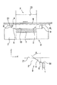
この場合、チップ式切刃部1は、ダイ本体2の上面21より低い位置に設けられ、該切刃部1の刃先18の前記上面21に対する深さ位置Hは(図6(B)、図6(C))、ワークWを打ち抜いた場合であって(図7(C)に相当)、該ワークWが穴3の中に入り込んだときでも、該ワークWが弾性限界内にあり、打ち抜き後は(図7(D)に相当)元に戻る程度の適切な深さ位置である。
【0042】
また、ダイ本体2の(図6(B)、図6(C))上面21であって、チップ式切刃部1が設けられている穴3の周縁4がR部(図4の上図に相当)、又はなだらかな傾斜面(図4の下図に相当)となっている。
【0043】
これにより、周縁4が尖っていて例えば90°になっている場合に比べて、移動するワークWの下面が周縁4と干渉しても、その干渉が和らげられ、該ワークWには疵が付かず、またダイ金型Dの損傷も防止される。
【0044】
上記本発明の第3実施形態の構成によれば、ダイ本体2の上面21と同じ高さ位置に設定されたパスラインPL(図6)に沿ってワークWが移動しても、前記チップ式切刃部1が上面21より低い位置に設けられているので、移動するワークWが、該チップ式切刃部1の刃先18と接触しないようになり、該刃先18の損傷が少なくなり、そのため刃先18の寿命は長くなり、またワークWに疵が付かないようになるという効果がある。
【0045】
一方、前記図1〜図6に示すダイ金型Dと協働して打ち抜き加工を行うパンチ金型Pは、既述したように、上部タレット24(図7(A))に装着されている。
【0046】
即ち、前記上部タレット24には、リフトスプリング34を介してパンチガイド30が支持され、該パンチガイド30にはストリッパスプリング33を介してパンチヘッド32が支持されている。
【0047】
上記パンチヘッド32には、下方に延びるパンチドライバ35が取り付けられ、該パンチドライバ35は、前記パンチガイド30内に進入し、該パンチドライバ35には、パンチボディ31が取り付けられ、その先端がパンチ側の刃先23となっている。
【0048】
以下、上記構成を有する本発明の動作を、図7に基づいて説明する。
【0049】
先ず、よく知られているように、上部タレット24と(図7(A))下部タレット25を同期回転させて、所望の金型P、D、即ち、切刃部1が、ダイ本体2の上面21より低い位置に設けられている本発明のダイ金型Dと(例えば図1、図2)、それに対応するパンチ金型Pを加工位置Kにおいて選択し、クランプ13に把持されたワークWをパスラインPLに沿って移動させて前記加工位置Kに位置決めする。
【0050】
次に、この状態で、ラム22(図7(B))を作動してパンチヘッド32を打圧すると、該パンチヘッド32が押し下げられ、リフトスプリング34が撓んでパンチ金型P全体が下降し、パンチガイド30下端のストリッパプレート37がワークWに当接してそれを押さえる。
【0051】
上記図7(B)の状態から、更にパンチヘッド32を押し下げると、今度はストリッパスプリング33が(図7(C))撓んでパンチボディ31がパンチガイド30に沿って下降し、その先端のパンチ金型P側の刃先23と、前記ダイ金型D側の刃先18とにより、ワークWが打ち抜かれ、カスW1が穴3を介して外部に排出される。
【0052】
その後、ラム22を(図7(D))上昇させてパンチ金型Pを初期位置に戻し、打ち抜き穴Aが形成されクランプ13に把持されたワークWをパスラインPLに沿って移動させる。
【0053】
この場合、図7に示す工程において、ワークWをパスラインPLに沿って移動させても(図7(A)、図7(D))、既述したように(例えば図1、図2)、切刃部1が、ダイ本体2の上面21より低い位置に設けられているので、移動するワークWが、切刃部1の刃先18と接触しないようになり、従って、該刃先18の損傷が少なくなり、そのため刃先18の寿命は長くなり、またワークWに疵が付かないようになる。
【0054】
また、ダイ本体2の上面21であって、切刃部1が設けられている穴3の周縁4がR部となっているので、移動するワークWの(図7(A)、図7(D))下面が周縁4と干渉しても、その干渉が和らげられ、該ワークWには疵が付かず、またダイ金型Dの損傷も防止される。
【0055】
更に、既述したように、上記切刃部1の刃先18の深さ位置Hは(例えば図2)、ワークWを打ち抜いた場合であって(図7(C))、該ワークWが穴3の中に入り込んだときに、該ワークWが弾性限界内にあり、打ち抜き後は(図7(D))元に戻る程度の適切な深さ位置に設定されていることから、打ち抜き穴Aの周囲は垂れ下がることはない。
【0056】
【発明の効果】
上記本発明によれば、パンチ金型と協働してワークに所定のパンチ加工を施すダイ金型において、切刃部が、ダイ本体の上面より低い位置に設けられているように構成したことにより、上面と同じ高さ位置に設定されたパスラインに沿ってワークが移動しても、切刃部が上面より低い位置に設けられているので、移動するワークが、切刃部の刃先と接触しないようになり、該刃先の損傷が少なくなり、そのため刃先の寿命は長くなり、またワークに疵が付かないようになるという効果がある。
【0057】
【図面の簡単な説明】
【図1】本発明の第1実施形態を示す斜視図である。
【図2】図1の側面図である。
【図3】本発明の第2実施形態を示す斜視図である。
【図4】図3の側面図である。
【図5】本発明の第3実施形態を示す斜視図である。
【図6】図5の平面図と側面図である。
【図7】本発明の動作説明図である。
【図8】従来技術の構成説明図である。
【図9】従来技術の課題説明図である。
【符号の説明】
1 切刃部
2 ダイ本体
3 穴
4 周縁
5 平坦部
6 溝
7 ボルト
8、9 キー溝
18 切刃部1の刃先
19 切刃部を構成するチップの開口部
21 ダイ本体2の上面
22 ラム
23 パンチ金型Pの刃先
24 上部タレット
25 下部タレット
30 パンチガイド
31 パンチボディ
32 パンチヘッド
33 ストリッパスプリング
34 リフトスプリング
35 パンチドライバ
37 ストリッパプレート
51 ポールブランジャ
1A、1B、1C、1D 切刃部1を構成するチップのチップ片
2A、2B、2C、2D チップ片が挿入する溝
10、11、12、13、14、15、16、17 各チップ片1A、1B、1C、1Dの傾斜した端面
D ダイ金型
P パンチ金型
W1 カス[0001]
TECHNICAL FIELD OF THE INVENTION
The present invention relates to a die, and more particularly to a die in which a cutting edge is prevented from coming into contact with a work other than during punching.
[0002]
[Prior art]
A conventional punch press, for example, a turret punch press has a configuration shown in FIG. 8, in which a punch die P is mounted on an
[0003]
With this configuration, when the work W is carried into the turret punch press, the work W is grasped and moved by the
[0004]
In this case, a
[0005]
[Problems to be solved by the invention]
[0006]
However, in the conventional die D (FIG. 9), the
[0007]
That is, conventionally, the
[0008]
Therefore, when the work W moves, dust and burrs on the lower surface of the work W adhere to the
[0009]
As a result, the
[0010]
Accordingly, the frequency of replacing the die D is increased, and the lower surface of the work W is scratched, so that the product value of the processed work W is lost, and the work W must be processed again, and the processing efficiency is reduced. There are various adverse effects, such as doing so.
[0011]
SUMMARY OF THE INVENTION It is an object of the present invention to prolong the life of a cutting edge of a die and to prevent the work from being scratched by preventing the cutting edge from contacting the work other than during punching.
[0012]
[Means for Solving the Problems]
In order to solve the above problems, the present invention provides:
In a die die D for performing a predetermined punching process on a work W in cooperation with a punch die P,
The
[0013]
According to the configuration of the present invention, even if the workpiece W moves along the pass line PL (for example, FIG. 2) set at the same height position as the
[0014]
For this reason, in the die, by preventing the cutting edge from contacting the work other than at the time of punching, it is possible to extend the life of the cutting edge and prevent the work from being flawed.
[0015]
BEST MODE FOR CARRYING OUT THE INVENTION
Hereinafter, embodiments of the present invention will be described with reference to the accompanying drawings.
FIG. 1 is a perspective view showing a first embodiment according to the present invention.
[0016]
As is well known, the illustrated die D is mounted on a
[0017]
The die D shown in FIG. 1 has a
[0018]
The
[0019]
However, if the depth position H of the
[0020]
For this reason, the depth position H of the
[0021]
Further, a
[0022]
That is, if the
[0023]
Further, the
[0024]
As a result, even if the lower surface of the moving workpiece W interferes with the
[0025]
According to the configuration of the first embodiment of the present invention, even if the work W moves along the pass line PL (FIG. 2) set at the same height position as the
[0026]
FIG. 3 is a perspective view showing a second embodiment of the present invention. The difference from the first embodiment of FIG. 1 (FIG. 2) is that in FIG. 3 is that the
[0027]
In FIG. 3, a die D has a
[0028]
In the center of the
[0029]
The tip-
[0030]
With this configuration, the tip-
[0031]
In this case, the tip-
[0032]
In addition, on the
[0033]
Thereby, similarly, even if the lower surface of the moving workpiece W interferes with the
[0034]
According to the configuration of the second embodiment of the present invention, similarly, even if the work W moves along the pass line PL (FIG. 4) set at the same height position as the
[0035]
FIG. 5 is a perspective view showing a third embodiment of the present invention, which is the same as FIG. 3 (FIG. 4) in that the cutting
[0036]
Thereby, similarly to the second embodiment of FIG. 3, in addition to the cost reduction, the tip-type
[0037]
In FIG. 5, the
[0038]
When viewed from above, each of the
[0039]
On both sides of each of the
[0040]
With this configuration, each of the
[0041]
In this case, the tip-
[0042]
Also, on the
[0043]
As a result, even if the lower surface of the moving workpiece W interferes with the
[0044]
According to the configuration of the third embodiment of the present invention, even if the work W moves along the pass line PL (FIG. 6) set at the same height position as the
[0045]
On the other hand, the punch die P for performing the punching process in cooperation with the die die D shown in FIGS. 1 to 6 is mounted on the upper turret 24 (FIG. 7A) as described above. .
[0046]
That is, the
[0047]
A
[0048]
Hereinafter, the operation of the present invention having the above configuration will be described with reference to FIG.
[0049]
First, as is well known, by rotating the
[0050]
Next, in this state, when the ram 22 (FIG. 7B) is operated to press the
[0051]
When the
[0052]
Thereafter, the
[0053]
In this case, in the process shown in FIG. 7, even if the workpiece W is moved along the pass line PL (FIGS. 7A and 7D), as described above (for example, FIGS. 1 and 2). Since the
[0054]
Further, since the
[0055]
Further, as described above, the depth position H of the
[0056]
【The invention's effect】
According to the present invention, in the die die for performing a predetermined punching process on the work in cooperation with the punch die, the cutting blade portion is provided at a position lower than the upper surface of the die body. Therefore, even if the work moves along the pass line set at the same height position as the upper surface, since the cutting edge portion is provided at a position lower than the upper surface, the moving work is in contact with the cutting edge of the cutting edge portion. There is an effect that the blade does not come into contact with the blade and damage to the blade is reduced, so that the life of the blade is prolonged and the work is not scratched.
[0057]
[Brief description of the drawings]
FIG. 1 is a perspective view showing a first embodiment of the present invention.
FIG. 2 is a side view of FIG.
FIG. 3 is a perspective view showing a second embodiment of the present invention.
FIG. 4 is a side view of FIG. 3;
FIG. 5 is a perspective view showing a third embodiment of the present invention.
6 is a plan view and a side view of FIG.
FIG. 7 is a diagram illustrating the operation of the present invention.
FIG. 8 is an explanatory diagram of a configuration of a conventional technique.
FIG. 9 is an explanatory diagram of a problem in the related art.
[Explanation of symbols]
DESCRIPTION OF
Claims (4)
切刃部が、ダイ本体の上面より低い位置に設けられていることを特徴とするダイ金型。In die dies that perform predetermined punching on workpieces in cooperation with punch dies,
A die mold, wherein the cutting blade portion is provided at a position lower than the upper surface of the die body.
Priority Applications (1)
| Application Number | Priority Date | Filing Date | Title |
|---|---|---|---|
| JP2002288224A JP4222471B2 (en) | 2002-10-01 | 2002-10-01 | Die mold |
Applications Claiming Priority (1)
| Application Number | Priority Date | Filing Date | Title |
|---|---|---|---|
| JP2002288224A JP4222471B2 (en) | 2002-10-01 | 2002-10-01 | Die mold |
Publications (2)
| Publication Number | Publication Date |
|---|---|
| JP2004122158A true JP2004122158A (en) | 2004-04-22 |
| JP4222471B2 JP4222471B2 (en) | 2009-02-12 |
Family
ID=32280786
Family Applications (1)
| Application Number | Title | Priority Date | Filing Date |
|---|---|---|---|
| JP2002288224A Expired - Fee Related JP4222471B2 (en) | 2002-10-01 | 2002-10-01 | Die mold |
Country Status (1)
| Country | Link |
|---|---|
| JP (1) | JP4222471B2 (en) |
Citations (3)
| Publication number | Priority date | Publication date | Assignee | Title |
|---|---|---|---|---|
| JPS54104584U (en) * | 1978-01-07 | 1979-07-23 | ||
| JPS61172616U (en) * | 1981-09-15 | 1986-10-27 | ||
| JPH09164431A (en) * | 1995-12-14 | 1997-06-24 | Hitachi Ltd | Burring method |
-
2002
- 2002-10-01 JP JP2002288224A patent/JP4222471B2/en not_active Expired - Fee Related
Patent Citations (3)
| Publication number | Priority date | Publication date | Assignee | Title |
|---|---|---|---|---|
| JPS54104584U (en) * | 1978-01-07 | 1979-07-23 | ||
| JPS61172616U (en) * | 1981-09-15 | 1986-10-27 | ||
| JPH09164431A (en) * | 1995-12-14 | 1997-06-24 | Hitachi Ltd | Burring method |
Also Published As
| Publication number | Publication date |
|---|---|
| JP4222471B2 (en) | 2009-02-12 |
Similar Documents
| Publication | Publication Date | Title |
|---|---|---|
| CN201921936U (en) | Burr removal mold | |
| JP2611128B2 (en) | Cutting die for follow-up cutting | |
| US6397715B1 (en) | Slug-retaining punch press tool | |
| JP3216574B2 (en) | Press mold | |
| JP2005205430A (en) | Press working apparatus | |
| JP2004122158A (en) | Die | |
| CN109967595B (en) | Notebook computer shell cuts pivot limit equipment | |
| JPH0615381A (en) | Method for shearing sheet like material | |
| JP2002361333A (en) | Deburring method for press-formed article and die for deburring | |
| JP2011025383A (en) | Die for dividing multilayer substrate | |
| JP4604552B2 (en) | Die for press | |
| JP3064759U (en) | Punching mold | |
| JPH03247Y2 (en) | ||
| JPS63303678A (en) | Deburring method | |
| JPS60216938A (en) | Treatment of scrap in pressing | |
| JPH11221628A (en) | Punching method and its device | |
| JPH087944Y2 (en) | Press hole punching die discharge structure | |
| JP2000158059A (en) | Scrap floating prevention die device | |
| JP2003062624A (en) | Scrap material discharge structure of punch press device | |
| JPH043688Y2 (en) | ||
| CN106111796B (en) | Radial direction trimming mechanism and method for cutting edge in a kind of progressive die | |
| JPH06142784A (en) | Method for working joint in punch press | |
| CN113523109A (en) | Insulating sheet punching die for automobile | |
| JPS59150626A (en) | Blanking die in pressing | |
| JP2000135522A (en) | Skim rise prevention punching method and skim rise prevention punching die device |
Legal Events
| Date | Code | Title | Description |
|---|---|---|---|
| A621 | Written request for application examination |
Free format text: JAPANESE INTERMEDIATE CODE: A621 Effective date: 20050926 |
|
| A977 | Report on retrieval |
Free format text: JAPANESE INTERMEDIATE CODE: A971007 Effective date: 20070705 |
|
| A131 | Notification of reasons for refusal |
Free format text: JAPANESE INTERMEDIATE CODE: A131 Effective date: 20070724 |
|
| A521 | Written amendment |
Free format text: JAPANESE INTERMEDIATE CODE: A523 Effective date: 20070922 |
|
| A131 | Notification of reasons for refusal |
Free format text: JAPANESE INTERMEDIATE CODE: A131 Effective date: 20080729 |
|
| TRDD | Decision of grant or rejection written | ||
| A01 | Written decision to grant a patent or to grant a registration (utility model) |
Free format text: JAPANESE INTERMEDIATE CODE: A01 Effective date: 20081111 |
|
| A01 | Written decision to grant a patent or to grant a registration (utility model) |
Free format text: JAPANESE INTERMEDIATE CODE: A01 |
|
| A61 | First payment of annual fees (during grant procedure) |
Free format text: JAPANESE INTERMEDIATE CODE: A61 Effective date: 20081112 |
|
| R150 | Certificate of patent or registration of utility model |
Free format text: JAPANESE INTERMEDIATE CODE: R150 |
|
| FPAY | Renewal fee payment (event date is renewal date of database) |
Free format text: PAYMENT UNTIL: 20111128 Year of fee payment: 3 |
|
| FPAY | Renewal fee payment (event date is renewal date of database) |
Free format text: PAYMENT UNTIL: 20111128 Year of fee payment: 3 |
|
| FPAY | Renewal fee payment (event date is renewal date of database) |
Free format text: PAYMENT UNTIL: 20121128 Year of fee payment: 4 |
|
| FPAY | Renewal fee payment (event date is renewal date of database) |
Free format text: PAYMENT UNTIL: 20121128 Year of fee payment: 4 |
|
| FPAY | Renewal fee payment (event date is renewal date of database) |
Free format text: PAYMENT UNTIL: 20131128 Year of fee payment: 5 |
|
| S533 | Written request for registration of change of name |
Free format text: JAPANESE INTERMEDIATE CODE: R313533 |
|
| R350 | Written notification of registration of transfer |
Free format text: JAPANESE INTERMEDIATE CODE: R350 |
|
| LAPS | Cancellation because of no payment of annual fees |