JP2004120879A - Motor control method of electric vehicle - Google Patents
Motor control method of electric vehicle Download PDFInfo
- Publication number
- JP2004120879A JP2004120879A JP2002279821A JP2002279821A JP2004120879A JP 2004120879 A JP2004120879 A JP 2004120879A JP 2002279821 A JP2002279821 A JP 2002279821A JP 2002279821 A JP2002279821 A JP 2002279821A JP 2004120879 A JP2004120879 A JP 2004120879A
- Authority
- JP
- Japan
- Prior art keywords
- command value
- torque command
- electric vehicle
- speed
- control method
- Prior art date
- Legal status (The legal status is an assumption and is not a legal conclusion. Google has not performed a legal analysis and makes no representation as to the accuracy of the status listed.)
- Granted
Links
Images


Classifications
-
- Y—GENERAL TAGGING OF NEW TECHNOLOGICAL DEVELOPMENTS; GENERAL TAGGING OF CROSS-SECTIONAL TECHNOLOGIES SPANNING OVER SEVERAL SECTIONS OF THE IPC; TECHNICAL SUBJECTS COVERED BY FORMER USPC CROSS-REFERENCE ART COLLECTIONS [XRACs] AND DIGESTS
- Y02—TECHNOLOGIES OR APPLICATIONS FOR MITIGATION OR ADAPTATION AGAINST CLIMATE CHANGE
- Y02T—CLIMATE CHANGE MITIGATION TECHNOLOGIES RELATED TO TRANSPORTATION
- Y02T10/00—Road transport of goods or passengers
- Y02T10/60—Other road transportation technologies with climate change mitigation effect
- Y02T10/72—Electric energy management in electromobility
Abstract
Description
【0001】
【発明の属する技術分野】
本発明は、アクセルの操作量に対応する速度指令値と電動車両の走行速度とに基づいてトルク指令値を算出し、該トルク指令値に応じて走行用のモータを駆動する電動車両のモータ制御方法に関する。
【0002】
【従来の技術】
電動車両の走行用モータを制御する主な方法として、トルク制御および速度制御がある。
【0003】
トルク制御を採用する電動車両では、アクセルペダルの操作量が一定となっていても、斜面から平坦面に移る際や、起伏を有する路面を走行する際にはモータにかかる負荷が変化するので、電動車両の速度をコントロールすることが困難である。
【0004】
また、速度制御を採用する電動車両では、アクセルペダルの踏み込み量に応じて走行速度を制御しているが、メカニカルブレーキによる減速時には、当然ながら走行速度の指令値も低下させなければならない。従って、速度制御を行う制御部とメカニカルブレーキの機構とは連携して制御を行う必要がある。例えば、ブレーキの踏み込み状態を検出する検出手段がないと、電動車両の速度が低下した場合にその原因がメカニカルブレーキの操作による減速か、または登坂などの負荷変動による減速かを判断することができない。このような理由から、速度制御を行う場合には、ブレーキセンサによってメカニカルブレーキの操作状態を速度の制御部に知らせる必要があるとされている。
【0005】
電動車両にかかる負荷の変動に影響されずに安定した走行性を確保するために、トルク制御か速度制御のいずれか一方をスイッチによって運転者が選択するという技術が提案されている(例えば、特許文献1参照)。
【0006】
また、速度制御を採用する電動車両において、メカニカルブレーキの代わりに電磁ブレーキを用いる技術が提案されている(例えば、特許文献2参照)。この技術では、電磁ブレーキの制御と速度制御とが同じコントローラで制御されるので、ブレーキ状態の判断は容易である。
【0007】
【特許文献1】
特開平6−14404号公報(段落[0021])
【特許文献2】
特開平9−130913号公報(段落[0012]〜[0015])
【0008】
【発明が解決しようとする課題】
ところで、特許文献1の技術においては、運転中に運転者自らが走行状態を判断してスイッチを操作しなければならないという煩わしさがある。また、速度制御とトルク制御との違いを十分に認識していない運転者もおり、このような運転者は安定した走行を行うことができない。
【0009】
また、特許文献2の技術では、電磁ブレーキとブレーキスイッチが必要であるとともにブレーキスイッチの信号に基づいて電磁ブレーキの制御を行う必要があり、コストの高騰を招いている。
【0010】
仮に、特許文献2に示される例にメカニカルブレーキを採用しても、ブレーキの踏み込み状態を検出するための検出手段が必要であることには変わりがない。特に、ブレーキペダルとハンドブレーキの2つの制動系統がある場合には、ブレーキペダルとハンドブレーキの双方にブレーキスイッチを設ける必要がある。
【0011】
本発明はこのような課題を考慮してなされたものであり、運転者によるモータ制御方法の切り換え操作が不要で、しかも制動系統部の部品点数を低減することのできる電動車両のモータ制御方法を提供することを目的とする。
【0012】
【課題を解決するための手段】
本発明に係る電動車両のモータ制御方法は、アクセルの操作量に対応する速度指令値と電動車両の走行速度とに基づいてトルク指令値を算出し、該トルク指令値に応じて走行用のモータを駆動する電動車両のモータ制御方法において、前記アクセルの操作量が0に戻された際に、前記トルク指令値の符号が正であるとき、所定の減衰パターンに沿って前記トルク指令値を0まで変化させ、前記アクセルの操作量が0で、前記トルク指令値の符号が0以下であるとき、速度指令値が走行速度よりも大きくなっても前記トルク指令値を0以下の値に制限することを特徴とする。
【0013】
このようにすることにより、トルクの急変を防止し、電動車両を滑らかに減速させることができる。また、ブレーキを作用させて減速させようとしたときに、確実に電動車両を減速させることができる。
【0014】
この場合、前記減衰パターンは、時間の経過に従って前記トルク指令値の減衰率が大となるパターンとすると、電動車両の振動を伴うことなく減速動作に移行することができる。
【0015】
また、前記減衰パターンは、該減衰パターンの適用を開始するときのトルク指令値による区分と、時間の区分とにより複数の直線を接続して表すようにすると、減衰パターンに沿って前記トルク指令値を0まで変化させる処理が簡便になる。
【0016】
さらに、前記減衰パターンに沿って前記トルク指令値を0まで変化させる処理は、前記アクセルの操作量が0である間に1回のみ実行されるように、実行回数を制限するようにしてもよい。
【0017】
【発明の実施の形態】
以下、本発明に係る電動車両のモータ制御方法について好適な実施の形態を挙げ、添付の図1〜図8を参照しながら説明する。
【0018】
本実施の形態に係る電動車両のモータ制御方法は、図1に示す電動車両10において、主として、ECU(Electric Control Unit)12により実行される。
【0019】
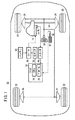
図1に示すように、電動車両10は、モータ14を動力源として走行するものであり、モータ14の回転軸が変速機能をもつディファレンシャルギア16に接続されている。モータ14の回転動力は、ディファレンシャルギア16および車軸18を介して前輪20に伝えられる。前輪20および後輪22にはそれぞれブレーキドラム24が接続されている。これらのブレーキドラム24は、ブレーキペダル26を踏み込むことによって図示しないマスターシリンダから液圧が加えられ、前輪20および後輪22の制動を行う。
【0020】
ECU12は、プログラム28に従って動作するCPU30の制御下に処理を行う。ECU12には、アクセルペダル32の踏み込み量を検出するボリューム34の信号が供給される。ECU12ではこのボリューム34の信号に基づいてモータ14に対する制御信号値を算出し、出力インターフェース(出力I/F)36に供給する。出力インターフェース36は、制御信号をインバータ38へ供給し、インバータ38は、バッテリ40から供給される電力を制御し、指令信号に基づいてモータ14を駆動する。
【0021】
モータ14には回転速度検出センサ42が設けられており、磁極の回転速度を検出する。この回転速度検出センサ42の信号は入力インターフェース(入力I/F)44を介してECU12に供給される。
【0022】
入力インターフェース44を介して供給される回転速度検出センサ42の信号は、ディファレンシャルギア16のギア比を乗算して車速v(図2参照)となる。
【0023】
なお、図1から明らかなように、各ブレーキドラム24は液圧によって操作されるものであって、所謂、メカニカルブレーキの一種である。従って、ブレーキペダル26およびブレーキドラム24は、ECU12等の電気システムとは無関係に制動力を発生することができる。また、ブレーキペダル26の踏み込み量をECU12等の電気システムに供給する手段(例えば、ボリューム等)は設けられていない。
【0024】
図2に示すように、ECU12は、アクセルペダル32の踏み込み量(操作量)を示すボリューム34の信号と回転速度検出センサ42の信号とに基づいて制御を行う。
【0025】
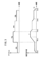
ECU12では、オン・オフ判断部50において、ボリューム34の信号と所定の小さい閾値とを比較し、その大小関係からアクセルペダル32のオンおよびオフ(操作量が0)を判断する。また、速度指令変換部52では、ボリューム34の信号から速度指令値cを算出する。つまり、図3に示すように、ボリューム34の信号と速度指令値cとは略比例的に対応し、ボリューム34の信号が変化するときには速度指令値cは所定の傾斜72を有するように変化する。
【0026】
図2に戻り、ECU12は、速度指令値cと車速vとを減算点54において減算する。この減算結果である速度偏差εをトルク指令部56において所定のゲインを乗算することによりトルク指令値Tを生成する。
【0027】
すなわち、アクセルペダル32の踏み込み量が速度指令変換部52を介して速度指令値cとなり、車速vをフィードバックしながら制御を行うので、基本的には車速制御を行うこととなる。
【0028】
車速制御を行うことで、負荷変動時や重負荷時にも速度の微妙なコントロールが可能であり、アクセルペダル32の踏み込みに対して急加速等の不測の挙動を起こすことがない。
【0029】
正トルク制限部58では、トルク指令部56から供給されるトルク指令値Tを負の値の範囲に制限した制限トルク指令値T1を生成する。つまり、トルク指令値Tの符号が正であるときには、制限トルク指令値T1を「0」とし、トルク指令値Tの符号が負であるときには、制限トルク指令値T1にトルク指令値Tを代入する。
【0030】
トルク指令減衰部60では、アクセルペダル32がオフになったときに、トルク指令値Tを基準として、減衰トルク指令値T2を図4に示すパターンに従って生成する。具体的には、図4に示すように、時間とトルク指令値Tとをそれぞれ4つの領域に分け、それぞれの領域に対して個別の減衰処理を行う。アクセルペダル32がオフになった時点を基準時間t0とし、順に第1時間t1までを領域U1、第2時間t2までを領域U2、第3時間t3までを領域U3、第3時間t3以降を領域U4と区分している。また、トルク指令値Tがp1以下の部分を領域V1、p1〜p2の部分を領域V2、p2〜p3の部分を領域V3、トルク指令値Tがp3以上の部分を領域V4と区分している。さらに、トルク指令値Tの減衰率は値の大きい順にD1、D2、D3、D4の4つが用意されており、この中から選択的に設定される。減衰率D2、D3、D4はそれぞれ減衰率D1を基準にして、例えば、D2=0.75×D1、D3=0.5×D1、D4=0.25×D1と設定するとよい。図4の例では、減衰率D1を実線、減衰率D2を一点鎖線、減衰率D3を点線、減衰率D4を二重線で表している。
【0031】
アクセルペダル32がオフになった時点、つまり基準時間t0で、トルク指令値Tが領域V4の範囲内であるときには、領域U1では減衰率D4、領域U2では減衰率D3、領域U3では減衰率D2、領域U4では減衰率D1を適用して減衰トルク指令値T2を生成する。
【0032】
基準時間t0で、トルク指令値Tが領域V3の範囲内であるときには、領域U1では減衰率D3、領域U2では減衰率D2、領域U3およびU4では減衰率D1を適用して減衰トルク指令値T2を生成する。
【0033】
基準時間t0で、トルク指令値Tが領域V2の範囲内であるときには、領域U1では減衰率D2、領域U2、U3、U4では減衰率D1を適用して減衰トルク指令値T2を生成する。
【0034】
基準時間t0で、トルク指令値Tが領域V1の範囲内であるときには、領域U1〜U4で減衰率D1を適用して減衰トルク指令値T2を生成する。
【0035】
このように、トルク指令減衰部60においては、アクセルペダル32がオフになった時点におけるトルク指令値Tに基づいて減衰トルク指令値T2を生成する。減衰トルク指令値T2は次第に減衰し最終的には「0」になる。また、その減衰率は、アクセルペダル32がオフになった当初は小さい値であり、時間の経過に従って次第に大きくなるようにしている。さらに、トルク指令値Tが小さいほど減衰率の値を大きくしている。減衰トルク指令値T2をこのように生成することにより、モータ14の発振現象を防止することができる。
【0036】
また、減衰パターンつまり減衰トルク指令値T2は、初期のトルク指令値Tと時間の経過とによって区分し、区分ごとに設定される直線を接続して表すことができるので、複雑な演算が不要である。
【0037】
図2に戻り、スイッチ部62は、3つの入力部62a、62b、62cのいずれか1つが有効になるスイッチ機能を有する。トルク指令部56が出力するトルク指令値Tはスイッチ部62の入力部62aに供給されている。正トルク制限部58が出力する制限トルク指令値T1はスイッチ部62の入力部62bに供給されている。トルク指令減衰部60が出力する減衰トルク指令値T2はスイッチ部62の入力部62cに供給されている。
【0038】
スイッチ切換判断部64では、アクセルペダル32のオン・オフ状態とトルク指令値Tとに基づいて処理を行い、スイッチ部62の入力部62a、62b、62cから1つを選択して出力させる機能を有する。スイッチ切換判断部64では、アクセルペダル32がオンのときには、スイッチ部62の入力部62aを有効にし、アクセルペダル32がオフになったときにトルク指令値Tが正であればスイッチ部62の入力部62cを有効にし、トルク指令減衰部60の処理後、スイッチ部62の入力部62bを有効にする。また、アクセルペダル32がオフになったときにトルク指令値Tが0以下であればスイッチ部62の入力部62bを有効にする。
【0039】
なお、図2に示すECU12内の各機能は、実際上はプログラム28に記録された処理であり、CPU30により実行される。
【0040】
次に、このように構成されるアクセルペダル32、ECU12、インバータ38等を用いてモータ14を制御する方法について図5〜図8を参照しながら説明する。図5のフローチャートは、主にCPU30がプログラム28の内容に基づいて行うものであり、所定の微小時間の周期で繰り返し実行される。
【0041】
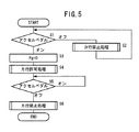
まず、図5のステップS1において、アクセルペダル32がオンかオフかを判断する。この処理は、オン・オフ判断部50において行われる。アクセルペダル32がオフである間は、無限ループによってステップS2の力行禁止処理を連続実行する。アクセルペダル32がオンであるときには、次のステップS3に移る。ここで、力行とはモータ14に正のトルクを発生させる運転状態をいう。ステップS2の力行禁止処理については後述する。
【0042】
ステップS3においては、フラグFgを「0」に設定する。このフラグFgは、後述する力行禁止処理において参照または再設定される。なお、フラグFgは初期状態においても「0」と設定されているものとする。
【0043】
次に、ステップS4において、力行許可処理を行う。ここで、力行許可処理とは、スイッチ切換判断部64によりスイッチ部62の入力部62aを有効にする処理である。このようにすることによって、トルク指令値Tが出力インターフェース36およびインバータ38を介してモータ14に供給されてモータ14が回転する。このとき、モータ14の発生するトルクは速度偏差εに対応したトルクとなるので、結果として、電動車両10はアクセルペダル32の速度指令値cに対応した速度で走行するようになる。
【0044】
次に、ステップS5において、アクセルペダル32がオンかオフかを判断する。アクセルペダル32がオンである間は、ステップS5の判断を連続実行する。アクセルペダル32がオフであるときには、ステップS6の力行禁止処理を行い、その後に今回の処理を終了する。
【0045】
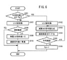
次に、力行禁止処理について図6を参照しながら説明する。図6のフローチャートで示される力行禁止処理は、前記ステップS2またはステップS6で実行されるものである。
【0046】
まず、図6のステップS101において、トルク指令値Tが正であり、かつ、フラグFgが「0」であるか否かを判断する。トルク指令値Tが正であり、かつ、フラグFgが「0」である場合にはステップS102に移り、トルク指令値Tが負であるか、または、フラグFgが「1」である場合にはステップS107に移る。つまり、このステップS101では、トルク指令値Tに応じて処理を区分し、さらにステップS102以降の処理をフラグFgによって実行制限をしている。
【0047】
ステップS102においては、スイッチ切換判断部64によりスイッチ部62の切り換えを行い入力部62cを有効にする。
【0048】
次に、ステップS108において、トルク指令減衰部60により図4に示すパターンに沿って、減衰トルク指令値T2を生成する。具体的には、アクセルペダル32がオフになった時間t0からの計時によって領域U1〜U4のいずれかを判断する。さらに、この領域U1〜U4に基づいて、減衰率D1〜D4のいずれか1つを選択して減衰トルク指令値T2を生成する。例えば、減衰率がD1であるときには、減衰トルク指令値T2の一度に減少する量が大きく、減衰率がD4であるときには一度に減少する量が小さい。
【0049】
次に、ステップS104において、速度指令値cを車速vに強制的に一致させて、速度偏差εおよびトルク指令値Tを「0」とする。この処理の結果は、ステップS107〜S110で利用される。
【0050】
次に、ステップS105において、トルク指令減衰部60の出力するトルク指令値Tの正/負の符号を確認する。トルク指令値Tが正であるときには、ステップS103へ戻り、減衰トルク指令値T2の生成処理を継続する。減衰トルク指令値T2が「0」になったときには次のステップS106に移る。
【0051】
ステップS106において、フラグFgを「1」にセットする。
【0052】
ステップS102〜S106は、図7に示すように、アクセルペダル32がオンからオフに移る時であって、かつトルク指令値Tが正であるときに実行される。このとき、減衰トルク指令値T2は減衰線70で示されるように徐々に減衰する。
【0053】
登坂中には、電動車両10には自重による下り方向の力が作用しているので、仮に、登り方向の力として作用しているトルクが急になくなると、電動車両10は急減速することとなる。本実施の形態では減衰トルク指令値T2を減衰線70にように徐々に減衰させているので、急減速を防止することができる。さらに、その減衰パターンは、時間とともに減衰率が大きくなるようにしているので、より滑らかに減速させることができる。
【0054】
なお、減衰線70は時間の経過に従って減衰率が大きくなり減衰トルク指令値T2は比較的速やかに「0」となるので、この間にブレーキペダル26がオンとなった場合も制動操作に与える影響は極めて小さい。
【0055】
また、ステップS1およびS2(図5参照)のループによって力行禁止処理が連続的に実行されるときには、このステップS102〜S106はフラグFgの設定値によって実行が制限されるので、最初の1回のみ実行される。なぜなら、登坂中にアクセルペダル32をオフにしたときに、図3の傾斜72に示すように速度指令値cは瞬時には「0」にならず、しかも登坂中は自重による減速度が大きいために速度指令値cが車速vより大きい値になり力行の状態となるが、このときは再度減衰トルク指令値T2の生成処理を行う必要がない。従って、フラグFgの作用によって、ステップS102〜S106の実行を制限し、代わりにステップS107〜S110の処理を行う。
【0056】
このとき、予めステップS104において速度偏差εおよびトルク指令値Tを「0」にしているので、処理の切り換え時に急な加減速が発生しない。
【0057】
一方、前記ステップS101において、トルク指令値Tが負であるか、または、フラグFgが「1」である場合にはステップS107に移る。このステップS107においては、スイッチ切換判断部64によりスイッチ部62の切り換えを行い入力部62bを有効にする。
【0058】
次に、ステップS108において、トルク指令値Tの符号を確認する。トルク指令値Tが正であるときには、ステップS109に移る。なお、トルク指令値Tは、速度偏差εに対してゲインを乗算したものであるから、ステップS108では速度偏差εの符号により分岐先を判断してもよい。ステップS109においては、トルク指令値Tを「0」に制限して制限トルク指令値T1を生成する。
【0059】
次のステップS110では、速度指令値cに車速vを代入し、速度偏差εを0にする処理を行う。
【0060】
ステップS107〜S110は、図8に示すように、アクセルペダル32がオンからオフに移る時であって、かつトルク指令値Tが負であるときに実行される。このとき、速度指令値cは、図3の傾斜72と同様に所定の傾斜をもって減少する。速度指令値cが「0」にまで減少する以前に運転者がブレーキペダル26(図1参照)を踏むとブレーキドラム24が作用して電動車両10は減速する。
【0061】
このとき、速度指令値cと車速vとの大小関係が反転し、車速vより速度指令値cの方が大きくなることがある。この場合、ECU12では、ブレーキペダル26の状態を検出していないので、速度偏差εは正の値となり、トルク指令部56は正の値を出力して入力部62aに供給する。仮に、この入力部62aに供給された正の値を用いてモータ14を回転させると、モータ14に正のトルクが発生することとなり、減速させようとしている運転者の意思に反する動作となり不都合である。
【0062】
本実施の形態では、ステップS107の処理によってスイッチ部62の入力部62aは無効で、入力部62bが有効となっている。入力部62bは、ステップS108〜S110に相当する正トルク制限部58に接続されており、正の値を「0」に制限した制限トルク指令値T1を供給するので、上記のような不都合がない。すなわち、ブレーキペダル26を踏んで減速している最中に、速度指令値cが車速vより大きくなってもモータ14が力行を行うことがない。
【0063】
ステップS106、S110の処理の処理後またはステップS108においてトルク指令値Tが負であるときには今回の処理を終了する。
【0064】
なお、ステップS108においてトルク指令値Tが負であるときには、図示しない回生用充電装置を用いて回生制動を行うようにするとよい。
【0065】
上述したように、本実施の形態に係る電動車両のモータ制御方法によれば、アクセルペダル32をオフにした際に、トルク指令値Tが正であるとき、所定の減衰パターンに沿って減衰トルク指令値T2を「0」まで変化させるようにしたので、トルクの急変を防止し、滑らかに減速することができる。
【0066】
また、アクセルペダル32をオフにした際に、トルク指令値Tが負であるとき、アクセルペダル32がオフである間、トルク指令値Tを0以下の値に制限した制限トルク指令値T1を供給している。従って、ブレーキペダル26を踏んで減速させようとしたときに、モータ14が力行を行うことがなく、確実に電動車両10を減速させることができる。
【0067】
さらに、本実施の形態に係る電動車両のモータ制御方法によれば、運転者はモータ制御方法の切り換え操作を行う必要がないので、切り換え操作の煩わしさがない。しかも、状況に応じて適切なモータ制御方法が選択されるので安定した運転が可能となる。モータ制御方法の切り換え操作用のスイッチも不要である。
【0068】
電動車両10では、メカニカルブレーキの1つであるブレーキドラム24により制動を行うので、電磁的なブレーキおよびその制御手段が不要である。また、ブレーキペダル26には踏み込み量を検出するためのブレーキスイッチまたはボリューム等が不要である。従って、電動車両10の制動系統部を廉価な構成にすることができる。
【0069】
本発明に係る電動車両のモータ制御方法は、上述の実施の形態に限らず、本発明の要旨を逸脱することなく、種々の構成を採り得ることはもちろんである。
【0070】
【発明の効果】
以上説明したように、本発明に係る電動車両のモータ制御方法によれば、運転者によるモータ制御方法の切り換え操作が不要で、しかも制動系統部の部品点数を低減することができるという効果を達成し、かつ電動車両の制動系統部を廉価な構成にすることができる。
【0071】
また、ブレーキの操作量を検出しなくても、ブレーキ操作時にモータが正のトルクを発生することがなく安定した運転を行うことができる。
【図面の簡単な説明】
【図1】電動車両の駆動・制動系統部を示すブロック図である。
【図2】ECUおよびその関連機器のブロック図である。
【図3】速度指令変換部の入出力信号の変化を示すタイムチャートである。
【図4】トルク指令減衰部において減衰するトルク指令値のタイムチャートである。
【図5】本実施の形態に係る電動車両のモータ制御方法を示すフローチャートである。
【図6】力行禁止処理の方法を示すフローチャートである。
【図7】アクセルペダルの操作量が0に戻された際に、トルク指令値の符号が負であるときのトルク指令値、速度指令値、車速を示すタイムチャートである。
【図8】アクセルペダルの操作量が0に戻された際に、トルク指令値の符号が正であるときのトルク指令値、速度指令値、車速を示すタイムチャートである。
【符号の説明】
10…電動車両 12…ECU
14…モータ 24…ブレーキドラム
26…ブレーキペダル 28…プログラム
30…CPU 32…アクセルペダル
34…ボリューム 38…インバータ
40…バッテリ 42…回転速度検出センサ
50…オン・オフ判断部 52…速度指令変換部
54…減算点 56…トルク指令部
58…正トルク制限部 60…トルク指令減衰部
62…スイッチ部 62a、62b、62c…入力部
64…スイッチ切換判断部 ε…速度偏差
c…速度指令値 T…トルク指令値
T1…制限トルク指令値 T2…減衰トルク指令値
v…車速[0001]
TECHNICAL FIELD OF THE INVENTION
The present invention provides a motor control for an electric vehicle that calculates a torque command value based on a speed command value corresponding to an accelerator operation amount and a traveling speed of the electric vehicle, and drives a driving motor in accordance with the torque command value. About the method.
[0002]
[Prior art]
The main methods for controlling the traveling motor of an electric vehicle include torque control and speed control.
[0003]
In an electric vehicle that employs torque control, even when the operation amount of the accelerator pedal is constant, the load applied to the motor changes when moving from a slope to a flat surface or when traveling on an uneven road surface, It is difficult to control the speed of the electric vehicle.
[0004]
In an electric vehicle employing speed control, the traveling speed is controlled in accordance with the amount of depression of an accelerator pedal. However, when the vehicle is decelerated by a mechanical brake, the traveling speed command value must be naturally reduced. Therefore, it is necessary to perform control in cooperation with the control unit that performs speed control and the mechanism of the mechanical brake. For example, if there is no detecting means for detecting the depression state of the brake, when the speed of the electric vehicle decreases, it is not possible to determine whether the cause is deceleration due to operation of a mechanical brake or deceleration due to load fluctuation such as climbing a slope. . For this reason, it is said that when speed control is performed, it is necessary to notify the operating state of the mechanical brake to a speed control unit using a brake sensor.
[0005]
In order to ensure stable traveling performance without being affected by a change in load applied to an electric vehicle, a technique has been proposed in which a driver selects either torque control or speed control by a switch (for example, see Patent Reference 1).
[0006]
Further, in an electric vehicle that adopts speed control, a technique using an electromagnetic brake instead of a mechanical brake has been proposed (for example, see Patent Document 2). In this technique, the control of the electromagnetic brake and the speed control are controlled by the same controller, so that it is easy to determine the brake state.
[0007]
[Patent Document 1]
JP-A-6-14404 (paragraph [0021])
[Patent Document 2]
JP-A-9-130913 (paragraphs [0012] to [0015])
[0008]
[Problems to be solved by the invention]
By the way, in the technique of
[0009]
Further, in the technique of
[0010]
Even if a mechanical brake is used in the example shown in
[0011]
The present invention has been made in view of such a problem, and a motor control method for an electric vehicle that does not require a driver to switch the motor control method and that can reduce the number of parts of a braking system unit. The purpose is to provide.
[0012]
[Means for Solving the Problems]
A motor control method for an electric vehicle according to the present invention calculates a torque command value based on a speed command value corresponding to an operation amount of an accelerator and a traveling speed of the electric vehicle, and a motor for traveling according to the torque command value. In the motor control method for an electric vehicle for driving the vehicle, when the operation amount of the accelerator is returned to 0 and the sign of the torque command value is positive, the torque command value is set to 0 along a predetermined attenuation pattern. When the operation amount of the accelerator is 0 and the sign of the torque command value is 0 or less, the torque command value is limited to a value of 0 or less even if the speed command value becomes larger than the traveling speed. It is characterized by the following.
[0013]
By doing so, a sudden change in torque can be prevented, and the electric vehicle can be smoothly decelerated. Further, when the brake is applied to decelerate, the electric vehicle can be surely decelerated.
[0014]
In this case, if the damping pattern is a pattern in which the damping rate of the torque command value increases as time passes, it is possible to shift to a deceleration operation without vibration of the electric vehicle.
[0015]
Further, when the attenuation pattern is expressed by connecting a plurality of straight lines by a section based on a torque command value when the application of the attenuation pattern is started and a section of time, the torque command value is determined along the attenuation pattern. Is simplified to 0.
[0016]
Furthermore, the number of executions of the process of changing the torque command value to 0 along the damping pattern may be limited so that the process is executed only once while the operation amount of the accelerator is 0. .
[0017]
BEST MODE FOR CARRYING OUT THE INVENTION
Hereinafter, a preferred embodiment of a motor control method for an electric vehicle according to the present invention will be described with reference to FIGS.
[0018]
The motor control method for an electric vehicle according to the present embodiment is mainly executed by an ECU (Electric Control Unit) 12 in
[0019]
As shown in FIG. 1, the
[0020]
The ECU 12 performs processing under the control of the
[0021]
The
[0022]
The signal of the rotation
[0023]
As is clear from FIG. 1, each
[0024]
As shown in FIG. 2, the
[0025]
In the
[0026]
Returning to FIG. 2, the
[0027]
That is, the depression amount of the
[0028]
By performing the vehicle speed control, the speed can be delicately controlled even when the load fluctuates or under heavy load, and unexpected behavior such as sudden acceleration when the
[0029]
The positive
[0030]
When the
[0031]
When the
[0032]
At the reference time t0, when the torque command value T is within the range of the area V3, the damping rate D3 is applied in the area U1, the damping rate D2 is applied in the area U2, and the damping rate D1 is applied in the areas U3 and U4. Generate
[0033]
When the torque command value T is within the range of the area V2 at the reference time t0, the damping torque command value T2 is generated by applying the damping rate D2 in the area U1 and the damping rate D1 in the areas U2, U3, and U4.
[0034]
When the torque command value T is within the range of the region V1 at the reference time t0, the damping torque command value T2 is generated by applying the damping rate D1 in the regions U1 to U4.
[0035]
Thus, the torque
[0036]
Further, the damping pattern, that is, the damping torque command value T2 can be divided by the initial torque command value T and the passage of time, and can be represented by connecting straight lines set for each section, so that complicated calculations are unnecessary. is there.
[0037]
Returning to FIG. 2, the
[0038]
The switch
[0039]
Each function in the
[0040]
Next, a method of controlling the
[0041]
First, in step S1 of FIG. 5, it is determined whether the
[0042]
In step S3, the flag Fg is set to “0”. This flag Fg is referred to or reset in the powering prohibition process described later. It is assumed that the flag Fg is set to “0” even in the initial state.
[0043]
Next, in step S4, power running permission processing is performed. Here, the power running permission process is a process of enabling the
[0044]
Next, in step S5, it is determined whether the
[0045]
Next, the powering prohibition process will be described with reference to FIG. The powering prohibition process shown in the flowchart of FIG. 6 is executed in step S2 or step S6.
[0046]
First, in step S101 of FIG. 6, it is determined whether the torque command value T is positive and the flag Fg is “0”. If the torque command value T is positive and the flag Fg is “0”, the process proceeds to step S102, and if the torque command value T is negative or the flag Fg is “1”, Move to step S107. That is, in step S101, the processing is divided according to the torque command value T, and the execution of the processing after step S102 is restricted by the flag Fg.
[0047]
In step S102, the
[0048]
Next, in step S108, the
[0049]
Next, in step S104, the speed command value c is forcibly made to match the vehicle speed v, and the speed deviation ε and the torque command value T are set to “0”. The result of this processing is used in steps S107 to S110.
[0050]
Next, in step S105, the positive / negative sign of the torque command value T output from the
[0051]
In step S106, the flag Fg is set to "1".
[0052]
Steps S102 to S106 are executed when the
[0053]
During climbing a hill, a downward force due to its own weight acts on the
[0054]
Since the attenuation rate of the
[0055]
When the power running prohibition process is continuously performed by the loop of steps S1 and S2 (see FIG. 5), the execution of steps S102 to S106 is restricted by the set value of the flag Fg, so that only the first one is performed. Be executed. This is because, when the
[0056]
At this time, since the speed deviation ε and the torque command value T are previously set to “0” in step S104, no rapid acceleration / deceleration occurs when the process is switched.
[0057]
On the other hand, when the torque command value T is negative or the flag Fg is “1” in step S101, the process proceeds to step S107. In this step S107, the
[0058]
Next, in step S108, the sign of the torque command value T is confirmed. When the torque command value T is positive, the process proceeds to step S109. Since the torque command value T is obtained by multiplying the speed deviation ε by the gain, the branch destination may be determined in step S108 based on the sign of the speed deviation ε. In step S109, the torque command value T is limited to "0" to generate a limited torque command value T1.
[0059]
In the next step S110, a process of substituting the vehicle speed v for the speed command value c and setting the speed deviation ε to 0 is performed.
[0060]
Steps S107 to S110 are executed when the
[0061]
At this time, the magnitude relationship between the speed command value c and the vehicle speed v may be reversed, and the speed command value c may be larger than the vehicle speed v. In this case, since the state of the
[0062]
In the present embodiment, the
[0063]
After the processing in steps S106 and S110 or when the torque command value T is negative in step S108, the current processing ends.
[0064]
When the torque command value T is negative in step S108, regenerative braking may be performed using a regenerative charging device (not shown).
[0065]
As described above, according to the motor control method for the electric vehicle according to the present embodiment, when the
[0066]
Further, when the
[0067]
Furthermore, according to the motor control method for the electric vehicle according to the present embodiment, the driver does not need to perform the switching operation of the motor control method, so that the switching operation is not troublesome. In addition, since an appropriate motor control method is selected according to the situation, stable operation is possible. A switch for switching the motor control method is not required.
[0068]
In the
[0069]
The motor control method of the electric vehicle according to the present invention is not limited to the above-described embodiment, but may adopt various configurations without departing from the gist of the present invention.
[0070]
【The invention's effect】
As described above, according to the motor control method for an electric vehicle according to the present invention, it is not necessary for the driver to perform a switching operation of the motor control method, and the number of components of the braking system can be reduced. In addition, the braking system of the electric vehicle can be configured to be inexpensive.
[0071]
Further, even if the operation amount of the brake is not detected, a stable operation can be performed without generating a positive torque by the motor during the brake operation.
[Brief description of the drawings]
FIG. 1 is a block diagram showing a driving / braking system of an electric vehicle.
FIG. 2 is a block diagram of an ECU and related devices.
FIG. 3 is a time chart showing changes in input / output signals of a speed command converter.
FIG. 4 is a time chart of a torque command value attenuated in a torque command attenuator.
FIG. 5 is a flowchart illustrating a motor control method for the electric vehicle according to the present embodiment.
FIG. 6 is a flowchart illustrating a powering prohibition processing method.
FIG. 7 is a time chart showing a torque command value, a speed command value, and a vehicle speed when the sign of the torque command value is negative when the operation amount of the accelerator pedal is returned to 0;
FIG. 8 is a time chart showing a torque command value, a speed command value, and a vehicle speed when the sign of the torque command value is positive when the operation amount of the accelerator pedal is returned to 0;
[Explanation of symbols]
10: electric vehicle 12: ECU
14 ...
Claims (4)
前記アクセルの操作量が0に戻された際に、前記トルク指令値の符号が正であるとき、所定の減衰パターンに沿って前記トルク指令値を0まで変化させ、
前記アクセルの操作量が0で、前記トルク指令値が0以下であるとき、前記トルク指令値を0以下の値に制限する
ことを特徴とする電動車両のモータ制御方法。A motor control method for an electric vehicle that calculates a torque command value based on a speed command value corresponding to an accelerator operation amount and a traveling speed of the electric vehicle and drives a motor for traveling in accordance with the torque command value,
When the operation amount of the accelerator is returned to 0, when the sign of the torque command value is positive, the torque command value is changed to 0 along a predetermined attenuation pattern,
When the operation amount of the accelerator is 0 and the torque command value is 0 or less, the torque command value is limited to a value of 0 or less.
前記減衰パターンは、前記トルク指令値を基準にし、時間の経過に従って前記トルク指令値の減衰率が大となるパターンであることを特徴とする電動車両のモータ制御方法。The motor control method for an electric vehicle according to claim 1,
The motor control method for an electric vehicle, wherein the damping pattern is a pattern in which a damping rate of the torque command value increases with time with reference to the torque command value.
前記減衰パターンは、該減衰パターンの適用を開始するときのトルク指令値による区分と、時間の区分とにより複数の直線を接続して表されることを特徴とする電動車両のモータ制御方法。The motor control method for an electric vehicle according to claim 2,
The motor control method for an electric vehicle, wherein the damping pattern is represented by connecting a plurality of straight lines by a section based on a torque command value at the start of application of the damping pattern and a section of time.
前記減衰パターンに沿って前記トルク指令値を0まで変化させる処理は、前記アクセルの操作量が0である間に1回のみ実行されるように、実行回数を制限することを特徴とする電動車両のモータ制御方法。The motor control method for an electric vehicle according to any one of claims 1 to 3,
An electric vehicle characterized in that the number of executions of the process of changing the torque command value to 0 along the damping pattern is limited so that the process is performed only once while the operation amount of the accelerator is zero. Motor control method.
Priority Applications (1)
| Application Number | Priority Date | Filing Date | Title |
|---|---|---|---|
| JP2002279821A JP3935035B2 (en) | 2002-09-25 | 2002-09-25 | Motor control method for electric vehicle |
Applications Claiming Priority (1)
| Application Number | Priority Date | Filing Date | Title |
|---|---|---|---|
| JP2002279821A JP3935035B2 (en) | 2002-09-25 | 2002-09-25 | Motor control method for electric vehicle |
Publications (2)
| Publication Number | Publication Date |
|---|---|
| JP2004120879A true JP2004120879A (en) | 2004-04-15 |
| JP3935035B2 JP3935035B2 (en) | 2007-06-20 |
Family
ID=32274715
Family Applications (1)
| Application Number | Title | Priority Date | Filing Date |
|---|---|---|---|
| JP2002279821A Expired - Fee Related JP3935035B2 (en) | 2002-09-25 | 2002-09-25 | Motor control method for electric vehicle |
Country Status (1)
| Country | Link |
|---|---|
| JP (1) | JP3935035B2 (en) |
Cited By (3)
| Publication number | Priority date | Publication date | Assignee | Title |
|---|---|---|---|---|
| CN100402336C (en) * | 2004-11-19 | 2008-07-16 | 丰田自动车株式会社 | Vehicle and its control |
| JP7430974B2 (en) | 2022-03-17 | 2024-02-14 | 三菱ロジスネクスト株式会社 | Deceleration control device, industrial vehicle equipped with the device, deceleration control method, and deceleration control program |
| CN117565697A (en) * | 2024-01-15 | 2024-02-20 | 合众新能源汽车股份有限公司 | Torque response control method and device under vehicle extremely-fast loading working condition and electronic equipment |
-
2002
- 2002-09-25 JP JP2002279821A patent/JP3935035B2/en not_active Expired - Fee Related
Cited By (4)
| Publication number | Priority date | Publication date | Assignee | Title |
|---|---|---|---|---|
| CN100402336C (en) * | 2004-11-19 | 2008-07-16 | 丰田自动车株式会社 | Vehicle and its control |
| JP7430974B2 (en) | 2022-03-17 | 2024-02-14 | 三菱ロジスネクスト株式会社 | Deceleration control device, industrial vehicle equipped with the device, deceleration control method, and deceleration control program |
| CN117565697A (en) * | 2024-01-15 | 2024-02-20 | 合众新能源汽车股份有限公司 | Torque response control method and device under vehicle extremely-fast loading working condition and electronic equipment |
| CN117565697B (en) * | 2024-01-15 | 2024-04-16 | 合众新能源汽车股份有限公司 | Torque response control method and device under vehicle extremely-fast loading working condition and electronic equipment |
Also Published As
| Publication number | Publication date |
|---|---|
| JP3935035B2 (en) | 2007-06-20 |
Similar Documents
| Publication | Publication Date | Title |
|---|---|---|
| US7291090B2 (en) | Motor torque control system for vehicle | |
| KR101875641B1 (en) | System and method for torque control of electric vehicle | |
| US20220080942A1 (en) | Control Unit for Providing a One-Pedal Feel and/or a Creep Function | |
| KR101618453B1 (en) | one-pedal driving control method of electric car | |
| JP2004268901A (en) | Brake control system | |
| JP6583620B2 (en) | Control device for electric vehicle | |
| JP2004026146A (en) | Method and device for braking vehicle | |
| US20140005869A1 (en) | Industrial vehicle | |
| JP4301162B2 (en) | Acceleration / deceleration controller | |
| JP6371323B2 (en) | Braking device for vehicle | |
| JP6682952B2 (en) | Regenerative control device | |
| JP2019115226A (en) | Control device, control method and control system for electric vehicle | |
| US8121772B2 (en) | Headway distance maintenance supporting device and method | |
| CN111605407B (en) | Control device for electric vehicle | |
| JP5686721B2 (en) | Control device for electric vehicle | |
| JPH1132404A (en) | Travel motion control equipment for electric vehicle | |
| JP2009035128A (en) | Energy regeneration device for vehicle | |
| JP2010241245A (en) | Driving power controller for vehicle | |
| JP2003063365A (en) | Parking brake system | |
| JP3935035B2 (en) | Motor control method for electric vehicle | |
| JP2005039908A (en) | Regenerative braking control unit of hybrid vehicle | |
| JPH01275937A (en) | Creep torque control device for transmission | |
| JP2006151020A (en) | Acceleration/deceleration controller | |
| JP4321441B2 (en) | Acceleration / deceleration controller | |
| CN113260529B (en) | Control unit for providing single pedal feel and/or creep function |
Legal Events
| Date | Code | Title | Description |
|---|---|---|---|
| A621 | Written request for application examination |
Free format text: JAPANESE INTERMEDIATE CODE: A621 Effective date: 20041201 |
|
| A977 | Report on retrieval |
Free format text: JAPANESE INTERMEDIATE CODE: A971007 Effective date: 20060413 |
|
| A131 | Notification of reasons for refusal |
Free format text: JAPANESE INTERMEDIATE CODE: A131 Effective date: 20060425 |
|
| A521 | Written amendment |
Free format text: JAPANESE INTERMEDIATE CODE: A523 Effective date: 20060620 |
|
| TRDD | Decision of grant or rejection written | ||
| A01 | Written decision to grant a patent or to grant a registration (utility model) |
Free format text: JAPANESE INTERMEDIATE CODE: A01 Effective date: 20070313 |
|
| A61 | First payment of annual fees (during grant procedure) |
Free format text: JAPANESE INTERMEDIATE CODE: A61 Effective date: 20070316 |
|
| R150 | Certificate of patent or registration of utility model |
Free format text: JAPANESE INTERMEDIATE CODE: R150 |
|
| FPAY | Renewal fee payment (event date is renewal date of database) |
Free format text: PAYMENT UNTIL: 20100330 Year of fee payment: 3 |
|
| FPAY | Renewal fee payment (event date is renewal date of database) |
Free format text: PAYMENT UNTIL: 20110330 Year of fee payment: 4 |
|
| FPAY | Renewal fee payment (event date is renewal date of database) |
Free format text: PAYMENT UNTIL: 20110330 Year of fee payment: 4 |
|
| FPAY | Renewal fee payment (event date is renewal date of database) |
Free format text: PAYMENT UNTIL: 20120330 Year of fee payment: 5 |
|
| FPAY | Renewal fee payment (event date is renewal date of database) |
Free format text: PAYMENT UNTIL: 20130330 Year of fee payment: 6 |
|
| FPAY | Renewal fee payment (event date is renewal date of database) |
Free format text: PAYMENT UNTIL: 20130330 Year of fee payment: 6 |
|
| FPAY | Renewal fee payment (event date is renewal date of database) |
Free format text: PAYMENT UNTIL: 20140330 Year of fee payment: 7 |
|
| LAPS | Cancellation because of no payment of annual fees |