JP2004116247A - Mounting structure of guide rail and door opening/closing device using the same - Google Patents
Mounting structure of guide rail and door opening/closing device using the same Download PDFInfo
- Publication number
- JP2004116247A JP2004116247A JP2002284830A JP2002284830A JP2004116247A JP 2004116247 A JP2004116247 A JP 2004116247A JP 2002284830 A JP2002284830 A JP 2002284830A JP 2002284830 A JP2002284830 A JP 2002284830A JP 2004116247 A JP2004116247 A JP 2004116247A
- Authority
- JP
- Japan
- Prior art keywords
- mounting
- guide rail
- rail
- fixed
- opening
- Prior art date
- Legal status (The legal status is an assumption and is not a legal conclusion. Google has not performed a legal analysis and makes no representation as to the accuracy of the status listed.)
- Granted
Links
Images


Abstract
Description
【0001】
【発明の属する技術分野】
本発明は、クローゼット等の収納部に取付けられるガイドレールの取付構造に係り、特に、収納部の開口を開閉する扉等を装着しやすくするため長手方向に分割されたガイドレールの取付構造と、これを使用する扉開閉装置に関する。
【0002】
【従来の技術】
従来、この種のガイドレールの取付構造として、例えば図9(a)、(b)に示す構造のものがある。図9(a)に示す取付構造は、壁40等の開口部41に折戸42を取付けるものであり、開口部に沿ってガイドレール43を取付ビス等により水平に直接固定し、このガイドレールの立ち上がり面に吊車のローラ44をスライド可能に引掛けて、折戸42を吊下げる構造としている。
【0003】
また、図9(b)に示す構造は、ガイドレール45は略T型で下方に開口するレール溝を有し、このレール溝の内部に吊車46を挿入し、この吊車から折戸47等を吊下げている。このタイプのガイドレールの場合、ガイドレール45を分割して分割端部のレール溝の開口から吊車46を挿入するようにしている。
【0004】
【発明が解決しようとする課題】
ところで、前記構造のガイドレールの取付構造は、ガイドレールを取付ける壁面等の取付部材は、開口部周辺の強度が弱く、例えば大型の折戸をガイドレールに取付けると、ガイドレールに折戸の全重量がかかって変形する虞があった。また、開口部周辺へのガイドレールの取付は、例えば複数本のビスにより固定するため、取付作業が煩雑となっていた。特に、吊車をレール溝に挿入するためガイドレールが分割され複数の分割レール片から構成される場合、分割レール片の継ぎ目に段差や隙間が生じやすく、折戸の吊車が円滑にスライドできないという問題があった。
【0005】
本発明は、このような問題に鑑みてなされたものであって、その目的とするところは、壁面等の取付部材の開口部周辺を補強でき、ガイドレールを強固に、精度良く固定でき、吊車の円滑なスライドを可能とするガイドレールの取付構造を提供することにある。また、ガイドレールの取付作業が容易で、ガイドレールが分割され複数の分割レール片で構成される場合でも、分割レール片の継ぎ目部分の段差や隙間を最小とすることができ、吊車を円滑にスライドできるガイドレールの取付構造を提供することにある。さらに、前記のガイドレールの取付構造を使用した扉開閉構造を提供することにある。
【0006】
【課題を解決するための手段】
前記目的を達成すべく、本発明に係るガイドレールの取付構造は、開口部を有する壁面等の取付部材にガイドレールを取付ける構造であって、ガイドレールは、長手方向に沿って突出形成した取付リブを備え、取付部材の開口部の上辺に沿って、長手方向に取付溝を形成した桟部材を水平に固定し、桟部材の取付溝に、ガイドレールの取付リブを挿入して固定することを特徴とする。すなわち、ガイドレールから突出する取付リブを桟部材の取付溝に挿入したあと、ねじ止め、釘止め等により、ガイドレールを確実に桟部材に固定する。
【0007】
前記のごとく構成された本発明のガイドレールの取付構造は、取付部材の開口部の上部に、開口部に沿って桟部材を固定しているため開口部周辺を補強でき、重量の大きい折戸等を吊下げてもガイドレールが変形することを防止できる。また、桟部材の長手方向に沿って取付溝を形成してあり、ガイドレールの取付リブを取付溝に挿入した状態で例えばねじ止めで固定するため、取付作業が容易となる。さらに、ガイドレールが分割される場合でも、分割された分割レール片は取付溝をガイドとして固定されるため、継ぎ目部分の段差や隙間を最小限にでき、装着される折戸等の吊車を円滑にスライドさせることができる。
【0008】
また、本発明に係るガイドレールの取付構造の好ましい具体的な態様としては、前記桟部材は取付部材の垂直面から突出した状態で固定され、前記取付溝は取付部材の垂直面と対向する取付面に水平方向に開口するものであり、ガイドレールの取付リブは、垂直取付部から水平方向に突出することを特徴としている。すなわち、壁面の前方の垂直面に桟部材を突出して固定し、桟部材の取付溝は前方に向けて水平に開口し、ガイドレールの取付リブは後方に向けて水平に突出し、取付部材の前面から桟部材とガイドレールを前方に突出した状態で固定する。
【0009】
この構成によれば、桟部材及びガイドレールは取付部材の前方に突出して固定されるため、開口部を広く取ることができる。そして、水平に開口する取付溝に、ガイドレールの後方に突出する水平状の取付リブを挿入して容易に固定できる。また、桟部材の厚みにより折戸等は壁面等の取付部材から離れ、折戸等の取付部材への干渉を回避できる。
【0010】
さらに、本発明に係るガイドレールの取付構造の好ましい具体的な他の態様としては、桟部材は、前記取付溝が取付面の幅方向の中央に形成されることを特徴としている。この構成によれば、桟部材が幅方向に対称であるため、取付部材に固定するとき上下を確認することなく単純に固定することができ、容易に桟部材の固定が行える。
【0011】
本発明に係るガイドレールの取付構造の好ましいさらに他の具体的な態様としては、ガイドレールは長手方向に直交する分割面で2つに分割され、2つの分割レール片は分割面同士を対接させて桟部材に固定されることを特徴とする。この構成によれば、ガイドレールが分割されている場合でも、ガイドレールは取付リブを取付溝に挿入してから固定されるため、継ぎ目部分の段差や隙間を小さくすることができ、ガイドレールに支持される折戸等の吊車は、継ぎ目部分を円滑に通過してスライドできる。
【0012】
本発明に係る扉開閉装置は、前記のガイドレールの取付機構を使用して、取付部材に固定されたガイドレールに、扉をスライド可能に装着することを特徴とする。このように構成された扉開閉装置は、ガイドレールの取付けが容易に行え、ガイドレールの変形が防止されているため扉のスライドが容易に安定して行え、扉の開閉が円滑に行える。特に、ガイドレールが分割されるものであっても、折戸等の扉や吊車の円滑なスライドが可能となる。
【0013】
本発明に係る扉開閉装置の他の態様としては、前記の長手方向に直交する分割面で2つに分割されるガイドレールの取付機構を使用して、最初に固定された第1の分割レール片の開口端部に扉をスライド可能に挿入し、第2の分割レール片の分割面を前記第1の分割レール片の分割面に対接させて第1の分割レール片と連結することを特徴とする。この構成によれば、ガイドレールが分割されるものでも、最初に固定された分割レール片に、つぎに固定する分割レール片を押付けて分割面同士を対接させて固定するため、連結部分の段差や隙間を最小にすることができ、装着された扉を円滑にスライドさせることができる。
【0014】
【発明の実施の形態】
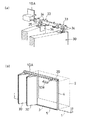
以下、本発明に係るガイドレールの取付構造を使用した扉開閉装置の一実施形態を図面に基づき詳細に説明する。図1は、本実施形態に係る扉開閉装置の概略斜視図、図2は、図1のガイドレール部分の要部断面図、図3はガイドレールと桟部材を離した状態の断面図、図4は折戸と、その要部を示す斜視図である。
【0015】
図1〜4において、ガイドレール10を取付ける取付部材である住宅の壁面1には、クローゼット等の収納部2に出入するための開口部3が形成されている。この開口部3の上辺に沿ってガイドレール10が桟部材20を介して取付けられ、ガイドレール10には開口部を開閉する扉として折戸30や引戸等が装着される。開口部3の左右の縦辺に沿って断面がL字状の縦枠4,4が固定され、縦枠の間の床面に下レール5と、下レールの両端に下ストッパー6,6が固定されている。なお、下レールは必ずしも必要でない。
【0016】
ガイドレール10は例えばアルミニウムの押出し材から形成され、その断面形状は垂直取付部11と、垂直取付部の上下方向の略中央部から水平方向に前方に向けて延出する上壁12と、この上壁の突出端部から垂下する側壁13と、垂直取付部11の下端部及び側壁13の下端部より内側に向けて延出して対向する2つの下壁14,15とから構成され、下壁14,15の間隙がレール溝16となっており、レール溝は下方に開口し、略T字状をしている。垂直取付部11の上壁12より上部には所定の間隔で複数の取付孔11aが穿設されている。ガイドレール10には長手方向に沿って、後方に向けて突出形成した取付リブ17が備えられている。すなわち、ガイドレール10の垂直取付部11には、幅方向の中央から上壁12と反対側に、すなわち壁面1の後方に向けて水平に延びるように取付リブ17が突出形成されている。
【0017】
ガイドレール10は長手方向に2つに分割され、長尺の主レール10Aと、短尺の継レール10Bとから構成され、主レール10Aと継レール10Bは断面形状が同じとなっている。このガイドレール10には、2つの下壁14,15の上面に後述する折戸30の吊車のローラが対接し、吊車の吊下げ軸がレール溝16から露出して下端に折戸30や引き戸等が吊下げられる構成である。
【0018】
壁面1の開口部3周囲には、左右の縦桟1aと上部の横桟1bが位置しており、縦桟及び横桟の前面には壁材1cが固定されている。本実施形態のガイドレールの取付構造では、開口部3の上辺に沿って補強用の桟部材20を水平に固定している。桟部材20は断面が正方形あるいは長方形である木製の棒から形成され、垂直面である壁面1から前方に突出して固定されている。桟部材20の壁面1への固定は、釘や木ねじ25を桟部材20を貫通して横桟1bに螺入し、あるいは接着剤等により壁材1cに接着により行われ、これらを併用して行ってもよい。なお、桟部材は木製に限らず、合成樹脂製や金属製のもの等、適宜のものを使用できる。
【0019】
桟部材20は壁面1に固定される背面20aと対向する前面20bに長手方向に沿って取付溝21が形成されている。この取付溝21は、桟部材20の前面の幅方向の中央に水平方向に形成され、前方に向けて開口している。そして、取付溝21にガイドレール10の取付リブ17が挿入できる構成となっている。本実施形態では、取付溝21の上下幅に対して取付リブ17の肉厚をわずかに大きく設定し、圧入状態に嵌合するようにしているが、取付溝の上下幅より取付リブを小さく設定し、両者が緩く嵌合するようにしてもよい。
【0020】
折戸30,30は、それぞれ2枚の戸31が使用され、2枚の戸31がヒンジ機構32により折りたためるように連結されている。2枚が連結された折戸30の両端の上部には吊車33が固定されている。吊車33は本体部の側面に4個のローラ34が回動可能に支持され、本体部の中央から下方に吊下げ軸35が固定され、吊下げ軸35と折戸30を支持するL型の金具36とは回転可能となっている。折戸の一方の戸31の下端にはガイドローラ37が固定され、折戸の他方の戸31の下端にラッチ38が固定されている。なお、下レール5を用いる開閉装置の場合はラッチ38を固定するが、下レールを用いない場合はラッチを固定しなくてよい。さらに、下レールを固定せず、開口部中央の床面にラッチ受け(図示せず)を設ける構成でもよい。
【0021】
前記の如く構成された本実施形態の扉開閉装置の取付動作について、図5〜8を参照して説明する。ガイドレール10を取付けようとする壁面1の前方の垂直面に、先ず図5(a)に示すように桟部材20を固定する。桟部材20は断面が長方形で、取付溝21が前方となるように釘や木ねじ25で開口部3の上辺に沿って固定する。木ねじ25は、ねじ頭が平坦な皿ねじが好ましい。
【0022】
本実施形態では、桟部材20の取付溝21の上半部はガイドレール10を固定する領域であり、取付溝21の下半部に木ねじ25をねじ込んで壁面1の内部の横桟1bに達するようにする。このように開口部3の上辺に沿って、開口部の前面に桟部材20を固定するため、開口部の開口面積を狭めることなく開口部の上辺を補強することができる。桟部材20の取付溝21は上下幅の中央に形成されているため、上下位置を確認することなく容易に固定することができる。
【0023】
つぎに、図5(a)に示すように、固定された桟部材20にガイドレール10を固定する。主レール10Aの垂直取付部11から水平方向に突出する取付リブ17を桟部材20の取付溝21に矢印のように挿入する。取付リブ17は取付溝21に圧入状態に保持されるため、従来のようにガイドレールを一方の手で支持して他方の手でねじ込んで固定するという煩雑な操作を不要として、ガイドレール10の取付孔11aに木ねじ26をねじ込んで容易に固定することができる。このようにして、主レール10Aを開口部3の上辺に沿って、容易にしかも確実に固定することができる。
【0024】
また、図5(b)に示すように、開口部3の左右の縦辺に沿って縦枠4,4を固定し、左右の縦枠の間の床面に下レール5と、下レールの両端の下ストッパー6,6を固定する。さらに、ガイドレール10の左右端に図7に示される上ストッパー7を固定する。下ストッパー6は詳細には図示していないが、下ストッパー6は折戸30のガイドローラ37の軸部を保持するものであり、上ストッパー7は吊車33の吊下げ軸35を保持して折戸30の端部を固定するものである。
【0025】
このあと、図6(a)に示すように、主レール10Aの端部の開口から折戸30の吊車33,33を挿入する。一方の折戸30の両端の吊車33を主レール10Aの開口から挿入して吊下げ、次いで他方の折戸30の両端の吊車33を主レール10Aの開口から挿入して吊下げる。そして、2組の折戸30を吊下げたあと、図6(b)に示すように、継レール10Bを固定する。
【0026】
すなわち、主レール10Aと同様に、継レール10Bの取付リブ17を桟部材20の取付溝21に挿入し、桟部材20に保持させた状態で木ねじ26により固定するので、容易に固定できる。継レール10Bは取付リブ17が桟部材20の取付溝21で位置決めされ、継レール10Bを主レール10A方向に押付け、主レールの分割面と継レールの分割面を対接させるため、継ぎ目部分の隙間や段差を極めて小さくすることができ、主レール10Aと正確に方向付けられて固定できる。また、主レール10A及び継レール10Bから構成されるガイドレール10は、桟部材20で補強された状態で固定されるため、重量の大きい折戸30や引戸を吊下げても、ガイドレール10の中央部が撓む等の変形を防止することができ、折戸30のスライド動作が安定して行える。
【0027】
つぎに、図7に示すように、上ストッパー7と吊車33の調整により、吊元の固定と折戸の調整を行う。上ストッパー7はガイドレール10の端部の開口から挿入され、左右位置を調整してドライバDにより固定する。また、吊車33の吊下げ軸35をスパナSで調整して折戸30の上下位置を調整し、2枚の戸31がガイドレール10に沿って円滑にスライドできるように調整する。なお、図7は説明のため、ガイドレール10と、上ストッパー7及び折戸30の吊車33とが分解した状態を示している。調整が完了すると、図1の状態となる。
【0028】
このあと、図8に示すように、ガイドレール10の外側に長手方向に沿って装飾用のレールカバー18を取付け、ガイドレール10の端部にサイドカバー19,19を固定する。レールカバー18はアルミニウムの押出し材から形成され、サイドカバー19は樹脂又はアルミダイキャストで形成される。レールカバー18を取付けることにより分割レール片である主レール10A、継レール10Bから構成されるガイドレール10は一直線上に規制され、吊車33のスライドがさらに円滑となる。また、継ぎ目部分が見えなくなるため、見栄えが良くなる。なお、レールカバー及びサイドカバーを取付けなくても機能的に問題はなく、これらは必ずしも必要でない。
【0029】
このように、本発明に係るガイドレールの取付構造は、開口部周辺を補強できるため、重量の大きい折戸等を吊下げてもガイドレールが変形することはない。また、ガイドレールの取付リブを取付溝に挿入した状態で固定するため、取付作業が容易となる。さらに、ガイドレールが分割される場合でも、継ぎ目部分の段差や隙間を最小限にできるため、装着される折戸等の吊車を円滑にスライドさせることができる。
【0030】
以上、本発明の一実施形態について詳述したが、本発明は、前記の実施形態に限定されるものではなく、特許請求の範囲に記載された本発明の精神を逸脱しない範囲で、種々の設計変更を行うことができるものである。例えば、扉開閉装置として、下レールのタイプの有る例を示したが、下レールの無いタイプや、下レールが無く中間部にラッチ受けの有るタイプ等、適宜のタイプに適用できる。
【0031】
また、ガイドレールに折戸等をスライド可能に装着する例として、吊車を介して装着する例を示したが、吊車を用いず例えば潤滑性を有する合成樹脂や、含油合金を使用するスライダーを使用して摺動させるようにしてもよい。さらに、桟部材には下方に開口する取付溝を形成し、ガイドレールには上方に突出する取付リブを形成し、取付溝に下方から取付リブを挿入して桟部材の下方にガイドレールを固定するようにしてもよい。
【0032】
【発明の効果】
以上の説明から理解できるように、本発明のガイドレールの取付構造は、開口部周辺を補強でき、重量の大きいガイドレールでも、変形することなしに取付けることができる。また、ガイドレールの取付作業が容易となる。そして、ガイドレールが分割される場合でも、継ぎ目部分の段差や隙間を最小限にでき、装着される折戸等の扉の吊車を円滑にスライドさせることができる。
【図面の簡単な説明】
【図1】本発明に係るガイドレールの取付構造を用いた扉開閉装置の一実施形態の概略斜視図。
【図2】図1のガイドレール部分の要部断面図。
【図3】図1,2に示すガイドレールと桟部材を離した状態の断面図。
【図4】折戸と、その要部を示す斜視図。
【図5】図1に示す扉開閉装置の取付動作を示し、(a)は桟部材の取付溝にガイドレールの取付リブを挿入する説明図、(b)は開口部に桟部材を固定し主レールを固定した状態の斜視図、(c)は下レール部の説明図。
【図6】図5に続く扉開閉装置の取付動作を示し、(a)は主レールに折戸の吊車を挿入する状態の説明図、(b)は2組の折戸を挿入し継レールを固定する状態の斜視図。
【図7】図6に続く扉開閉装置の取付動作を示し、吊元の固定と折戸の調整の説明図。
【図8】(a)はガイドレールにレールカバーとサイドカバーを取付ける状態の動作説明図、(b)はレールカバーとサイドカバーを取付け、折戸を閉めた状態の斜視図。
【図9】従来の扉開閉機構に使用するガイドレールの取付機構を示し、(a)はガイドレールの上部に吊車を引掛けるタイプの要部断面図、(b)はレール溝に吊車を挿入するタイプの要部断面図。
【符号の説明】
1 壁面(取付部材)、 2 収納部、
3 開口部、 10 ガイドレール、
10A 主レール(分割レール片)、
10B 継レール(分割レール片)、
11 ガイドレールの垂直取付部、
16 レール溝、 17 取付リブ、
20 桟部材、 21 取付溝、
25,26 木ねじ、
30 折戸(扉)、 33 吊車[0001]
TECHNICAL FIELD OF THE INVENTION
The present invention relates to a mounting structure of a guide rail mounted on a storage unit such as a closet, and particularly, a mounting structure of a guide rail divided in a longitudinal direction to facilitate installation of a door or the like that opens and closes an opening of the storage unit, The present invention relates to a door opening / closing device using the same.
[0002]
[Prior art]
Conventionally, as this type of guide rail mounting structure, for example, there is a structure shown in FIGS. 9 (a) and 9 (b). In the mounting structure shown in FIG. 9A, a folding
[0003]
In the structure shown in FIG. 9B, the
[0004]
[Problems to be solved by the invention]
By the way, in the guide rail mounting structure of the above structure, the mounting member such as a wall surface on which the guide rail is mounted has a low strength around the opening. For example, when a large folding door is mounted on the guide rail, the total weight of the folding door is reduced by the guide rail. There was a risk of deformation. In addition, the mounting of the guide rail around the opening is fixed by, for example, a plurality of screws, so that the mounting operation is complicated. In particular, when the guide rail is divided into a plurality of divided rail pieces to insert the hanging car into the rail groove, a step or a gap is easily generated at the joint of the divided rail pieces, and the problem that the hanging car of the folding door cannot slide smoothly. there were.
[0005]
The present invention has been made in view of such a problem, and an object thereof is to reinforce the periphery of an opening of a mounting member such as a wall surface, to fix a guide rail firmly and precisely, An object of the present invention is to provide a guide rail mounting structure that enables smooth sliding of the guide rail. In addition, the guide rail mounting work is easy, and even when the guide rail is divided and composed of a plurality of divided rail pieces, the steps and gaps at the joints of the divided rail pieces can be minimized, and the hanging wheel can be smoothly run. An object of the present invention is to provide a guide rail mounting structure that can slide. Another object of the present invention is to provide a door opening / closing structure using the guide rail mounting structure.
[0006]
[Means for Solving the Problems]
In order to achieve the above object, a guide rail mounting structure according to the present invention is a structure in which a guide rail is mounted on a mounting member such as a wall surface having an opening, and the guide rail is formed so as to protrude along a longitudinal direction. A rib provided with a rib, and a rail member having a mounting groove formed in the longitudinal direction along the upper side of the opening of the mounting member is horizontally fixed, and the mounting rib of the guide rail is inserted and fixed in the mounting groove of the rail member. It is characterized by. That is, after the mounting rib projecting from the guide rail is inserted into the mounting groove of the rail member, the guide rail is securely fixed to the rail member by screwing, nailing, or the like.
[0007]
The guide rail mounting structure of the present invention configured as described above is capable of reinforcing the periphery of the opening because the cross member is fixed along the opening above the opening of the mounting member, and a heavy folding door or the like can be provided. The guide rails can be prevented from being deformed even if they are suspended. Further, since the mounting groove is formed along the longitudinal direction of the crosspiece member, and the mounting rib of the guide rail is inserted into the mounting groove and fixed by, for example, screws, the mounting operation is facilitated. Furthermore, even when the guide rail is split, the split rail pieces are fixed using the mounting grooves as guides, so that the steps and gaps at the joints can be minimized, and the hanging wheels such as folding doors can be smoothly mounted. Can slide.
[0008]
In a preferred specific mode of the guide rail mounting structure according to the present invention, the crosspiece member is fixed in a state of protruding from a vertical surface of the mounting member, and the mounting groove has a mounting surface facing the vertical surface of the mounting member. The guide rail is horizontally opened, and the mounting rib of the guide rail projects horizontally from the vertical mounting portion. That is, the rail member is projected and fixed to the front vertical surface of the wall surface, the mounting groove of the rail member opens horizontally forward, the mounting rib of the guide rail projects horizontally rearward, and the front surface of the mounting member And the guide member and the guide rail are fixed so as to protrude forward.
[0009]
According to this configuration, the crosspiece member and the guide rail protrude forward from the mounting member and are fixed, so that the opening can be widened. Then, a horizontal mounting rib projecting rearward of the guide rail is inserted into the mounting groove that opens horizontally, and can be easily fixed. Further, the folding door or the like is separated from the mounting member such as the wall surface due to the thickness of the crosspiece member, and interference with the mounting member such as the folding door can be avoided.
[0010]
Furthermore, as another preferable specific specific embodiment of the guide rail mounting structure according to the present invention, the crosspiece is characterized in that the mounting groove is formed at the center in the width direction of the mounting surface. According to this configuration, since the bar member is symmetrical in the width direction, it can be simply fixed without checking the up and down when fixing to the mounting member, and the bar member can be easily fixed.
[0011]
As still another preferred specific embodiment of the guide rail mounting structure according to the present invention, the guide rail is divided into two by a division surface orthogonal to the longitudinal direction, and the two division rail pieces contact the division surfaces with each other. And fixed to the crosspiece member. According to this configuration, even when the guide rail is divided, the guide rail is fixed after inserting the mounting rib into the mounting groove. A supported hanging wheel such as an folding door can slide smoothly through the seam portion.
[0012]
The door opening and closing device according to the present invention is characterized in that the door is slidably mounted on the guide rail fixed to the mounting member using the guide rail mounting mechanism. In the door opening / closing device configured as described above, the guide rail can be easily attached, and the guide rail is prevented from being deformed, so that the door can be easily and stably slid, and the door can be smoothly opened / closed. In particular, even if the guide rail is divided, a door such as a folding door or a hanging car can be smoothly slid.
[0013]
According to another aspect of the door opening and closing device according to the present invention, a first split rail fixed first using a guide rail mounting mechanism that is split into two by a split surface orthogonal to the longitudinal direction. The door is slidably inserted into the open end of the piece, and the split face of the second split rail piece is brought into contact with the split face of the first split rail piece and connected to the first split rail piece. Features. According to this configuration, even when the guide rail is divided, the divided rail piece to be fixed next is pressed against the first fixed divided rail piece so that the divided surfaces are brought into contact with each other and fixed. Steps and gaps can be minimized, and the mounted door can be slid smoothly.
[0014]
BEST MODE FOR CARRYING OUT THE INVENTION
Hereinafter, an embodiment of a door opening and closing device using a guide rail mounting structure according to the present invention will be described in detail with reference to the drawings. 1 is a schematic perspective view of a door opening and closing device according to the present embodiment, FIG. 2 is a cross-sectional view of a main part of a guide rail portion of FIG. 1, and FIG. FIG. 4 is a perspective view showing a folding door and a main part thereof.
[0015]
1 to 4, an
[0016]
The
[0017]
The
[0018]
The left and right
[0019]
The
[0020]
Each of the
[0021]
The mounting operation of the door opening / closing device of the present embodiment configured as described above will be described with reference to FIGS. First, as shown in FIG. 5A, a
[0022]
In the present embodiment, the upper half of the mounting
[0023]
Next, as shown in FIG. 5A, the
[0024]
Also, as shown in FIG. 5B, the
[0025]
Thereafter, as shown in FIG. 6A, the hanging
[0026]
That is, as in the case of the
[0027]
Next, as shown in FIG. 7, by adjusting the upper stopper 7 and the
[0028]
Thereafter, as shown in FIG. 8, a
[0029]
As described above, since the guide rail mounting structure according to the present invention can reinforce the periphery of the opening, the guide rail is not deformed even when a heavy folding door or the like is hung. Further, since the mounting rib of the guide rail is fixed in a state of being inserted into the mounting groove, the mounting work becomes easy. Further, even when the guide rail is divided, the steps and gaps at the joints can be minimized, so that a hanging vehicle such as a folding door to be mounted can be slid smoothly.
[0030]
As described above, one embodiment of the present invention has been described in detail. However, the present invention is not limited to the above-described embodiment, and various modifications may be made without departing from the spirit of the present invention described in the appended claims. Design changes can be made. For example, as the door opening / closing device, an example in which a lower rail is used is shown. However, an appropriate type such as a type having no lower rail or a type having no lower rail and having a latch receiver in an intermediate portion can be applied.
[0031]
Also, as an example in which a folding door or the like is slidably mounted on the guide rail, an example in which the folding door is mounted via a suspension wheel has been described. You may make it slide. Furthermore, a mounting groove that opens downward is formed in the bar member, and a mounting rib that protrudes upward is formed in the guide rail, and the mounting rib is inserted into the mounting groove from below to fix the guide rail below the bar member. You may make it.
[0032]
【The invention's effect】
As can be understood from the above description, the guide rail mounting structure of the present invention can reinforce the periphery of the opening and can mount a heavy guide rail without deformation. In addition, the work of attaching the guide rail is facilitated. Then, even when the guide rail is divided, a step or a gap at a joint portion can be minimized, and a hanging wheel of a door such as a folding door to be mounted can be smoothly slid.
[Brief description of the drawings]
FIG. 1 is a schematic perspective view of an embodiment of a door opening / closing device using a guide rail mounting structure according to the present invention.
FIG. 2 is a sectional view of a main part of a guide rail portion of FIG.
FIG. 3 is a cross-sectional view of a state where the guide rail and the crosspiece shown in FIGS.
FIG. 4 is a perspective view showing a folding door and a main part thereof.
FIGS. 5A and 5B show the mounting operation of the door opening / closing device shown in FIG. 1, wherein FIG. 5A is an explanatory view of inserting a guide rail mounting rib into a mounting groove of a bar member, and FIG. FIG. 3C is a perspective view of a state where the main rail is fixed, and FIG.
6A and 6B show the mounting operation of the door opening / closing device following FIG. 5; FIG. 6A is an explanatory view showing a state where a folding door is inserted into a main rail; FIG. FIG.
FIG. 7 is an explanatory view showing the mounting operation of the door opening / closing device following FIG. 6, and illustrating the fixing of the hanging base and the adjustment of the folding door.
FIG. 8A is an operation explanatory view showing a state where a rail cover and a side cover are mounted on a guide rail, and FIG. 8B is a perspective view showing a state where the rail cover and the side cover are mounted and the folding door is closed.
9A and 9B show a guide rail mounting mechanism used for a conventional door opening and closing mechanism. FIG. 9A is a cross-sectional view of a main part of a type in which a hoist is hooked on the upper part of the guide rail, and FIG. FIG.
[Explanation of symbols]
1 wall surface (mounting member), 2 storage section,
3 opening, 10 guide rail,
10A main rail (split rail piece),
10B joint rail (split rail piece),
11 Vertical mounting part of guide rail,
16 rail groove, 17 mounting rib,
20 cross members, 21 mounting grooves,
25,26 wood screws,
30 Orido (door), 33 Hanging car
Claims (6)
前記ガイドレールは、長手方向に沿って突出形成した取付リブを備え、
前記取付部材の開口部の上辺に沿って、長手方向に取付溝を形成した桟部材を水平に固定し、
前記桟部材の取付溝に、前記ガイドレールの取付リブを挿入して固定することを特徴とするガイドレールの取付構造。A structure for mounting the guide rail on a mounting member such as a wall surface having an opening,
The guide rail includes a mounting rib projecting along the longitudinal direction,
Along the upper side of the opening of the mounting member, horizontally fix the cross member having the mounting groove formed in the longitudinal direction,
A guide rail mounting structure, wherein a mounting rib of the guide rail is inserted and fixed in a mounting groove of the crosspiece member.
前記ガイドレールの取付リブは、垂直取付部から水平方向に突出することを特徴とする請求項1に記載のガイドレールの取付構造。The cross member is fixed in a state protruding from a vertical surface of the mounting member, and the mounting groove is opened horizontally in a mounting surface facing the vertical surface of the mounting member,
The guide rail mounting structure according to claim 1, wherein the mounting rib of the guide rail projects horizontally from a vertical mounting portion.
Priority Applications (1)
| Application Number | Priority Date | Filing Date | Title |
|---|---|---|---|
| JP2002284830A JP3921158B2 (en) | 2002-09-30 | 2002-09-30 | Folding door opening and closing device |
Applications Claiming Priority (1)
| Application Number | Priority Date | Filing Date | Title |
|---|---|---|---|
| JP2002284830A JP3921158B2 (en) | 2002-09-30 | 2002-09-30 | Folding door opening and closing device |
Publications (2)
| Publication Number | Publication Date |
|---|---|
| JP2004116247A true JP2004116247A (en) | 2004-04-15 |
| JP3921158B2 JP3921158B2 (en) | 2007-05-30 |
Family
ID=32278270
Family Applications (1)
| Application Number | Title | Priority Date | Filing Date |
|---|---|---|---|
| JP2002284830A Expired - Fee Related JP3921158B2 (en) | 2002-09-30 | 2002-09-30 | Folding door opening and closing device |
Country Status (1)
| Country | Link |
|---|---|
| JP (1) | JP3921158B2 (en) |
Cited By (6)
| Publication number | Priority date | Publication date | Assignee | Title |
|---|---|---|---|---|
| JP2008075256A (en) * | 2006-09-19 | 2008-04-03 | Toyo Exterior Co Ltd | Expansion gate for parking lot for double-parking a plurality of vehicles |
| JP2013249588A (en) * | 2012-05-30 | 2013-12-12 | Skb:Kk | Opening and closing device |
| JP2014077265A (en) * | 2012-10-10 | 2014-05-01 | Bunka Shutter Co Ltd | Assembly and construction method of opening/closing device |
| JP2014098247A (en) * | 2012-11-13 | 2014-05-29 | Sankyotateyama Inc | Sliding door |
| KR101891758B1 (en) * | 2017-07-10 | 2018-09-28 | 주식회사 두문 | apparatus for moving a board and assembly including the same |
| JP2019044374A (en) * | 2017-08-30 | 2019-03-22 | 株式会社八木 | Rail-like member |
Families Citing this family (2)
| Publication number | Priority date | Publication date | Assignee | Title |
|---|---|---|---|---|
| JP2009068208A (en) * | 2007-09-11 | 2009-04-02 | Atom Livin Tech Co Ltd | Rail mounting structure |
| JP7382529B1 (en) | 2023-06-28 | 2023-11-16 | 清水 勇介 | carton and package |
-
2002
- 2002-09-30 JP JP2002284830A patent/JP3921158B2/en not_active Expired - Fee Related
Cited By (6)
| Publication number | Priority date | Publication date | Assignee | Title |
|---|---|---|---|---|
| JP2008075256A (en) * | 2006-09-19 | 2008-04-03 | Toyo Exterior Co Ltd | Expansion gate for parking lot for double-parking a plurality of vehicles |
| JP2013249588A (en) * | 2012-05-30 | 2013-12-12 | Skb:Kk | Opening and closing device |
| JP2014077265A (en) * | 2012-10-10 | 2014-05-01 | Bunka Shutter Co Ltd | Assembly and construction method of opening/closing device |
| JP2014098247A (en) * | 2012-11-13 | 2014-05-29 | Sankyotateyama Inc | Sliding door |
| KR101891758B1 (en) * | 2017-07-10 | 2018-09-28 | 주식회사 두문 | apparatus for moving a board and assembly including the same |
| JP2019044374A (en) * | 2017-08-30 | 2019-03-22 | 株式会社八木 | Rail-like member |
Also Published As
| Publication number | Publication date |
|---|---|
| JP3921158B2 (en) | 2007-05-30 |
Similar Documents
| Publication | Publication Date | Title |
|---|---|---|
| JP2004116247A (en) | Mounting structure of guide rail and door opening/closing device using the same | |
| JP3686617B2 (en) | Opening and closing mechanism of the hanging sliding door | |
| JP5516944B2 (en) | Folding door support structure and door support panel upper support fitting used in this support structure | |
| KR20120115879A (en) | Door assembly of a sliding window and assembling method threreof | |
| US7735262B2 (en) | Pocket door mounting system | |
| JP2003193737A (en) | Upper frame structure for sliding door, and its construction method | |
| JP2582013Y2 (en) | Panel structure for panel shutter | |
| JP2519420Y2 (en) | Furniture rail joint mechanism | |
| JP3974495B2 (en) | Door to be attached to opening of storage device or the like, and door opening / closing device having said door attached to opening | |
| JP2000199377A (en) | Sliding door device | |
| JP6083513B2 (en) | Upper frame and joinery device provided with the same | |
| JPH09268834A (en) | Hanging sliding door | |
| JP3353702B2 (en) | Hanging structure of sliding door | |
| JP3088889B2 (en) | Curtain plate mounting device | |
| JPS6339349Y2 (en) | ||
| JP6831212B2 (en) | Automatic door | |
| JPH11159231A (en) | Shielding structure for upper part of overhang door | |
| JP2566650Y2 (en) | Door structure for synthetic resin sliding doors | |
| JPH08128249A (en) | Closing positioning device of door and window | |
| JP3789907B2 (en) | Sliding door device | |
| JPH08326426A (en) | Sliding door mounting frame construction | |
| JP3121509B2 (en) | Structure of the lower rail of the folding door | |
| JPS5823895Y2 (en) | Shoji door car | |
| JP2573800Y2 (en) | Structure of lower rail of partitioning device | |
| JPH0443576Y2 (en) |
Legal Events
| Date | Code | Title | Description |
|---|---|---|---|
| A621 | Written request for application examination |
Free format text: JAPANESE INTERMEDIATE CODE: A621 Effective date: 20050906 |
|
| A977 | Report on retrieval |
Free format text: JAPANESE INTERMEDIATE CODE: A971007 Effective date: 20061020 |
|
| A131 | Notification of reasons for refusal |
Free format text: JAPANESE INTERMEDIATE CODE: A131 Effective date: 20061024 |
|
| A521 | Written amendment |
Free format text: JAPANESE INTERMEDIATE CODE: A523 Effective date: 20061222 |
|
| TRDD | Decision of grant or rejection written | ||
| A01 | Written decision to grant a patent or to grant a registration (utility model) |
Free format text: JAPANESE INTERMEDIATE CODE: A01 Effective date: 20070123 |
|
| A61 | First payment of annual fees (during grant procedure) |
Free format text: JAPANESE INTERMEDIATE CODE: A61 Effective date: 20070216 |
|
| R150 | Certificate of patent (=grant) or registration of utility model |
Free format text: JAPANESE INTERMEDIATE CODE: R150 |
|
| FPAY | Renewal fee payment (prs date is renewal date of database) |
Free format text: PAYMENT UNTIL: 20110223 Year of fee payment: 4 |
|
| FPAY | Renewal fee payment (prs date is renewal date of database) |
Free format text: PAYMENT UNTIL: 20110223 Year of fee payment: 4 |
|
| FPAY | Renewal fee payment (prs date is renewal date of database) |
Free format text: PAYMENT UNTIL: 20120223 Year of fee payment: 5 |
|
| FPAY | Renewal fee payment (prs date is renewal date of database) |
Free format text: PAYMENT UNTIL: 20120223 Year of fee payment: 5 |
|
| FPAY | Renewal fee payment (prs date is renewal date of database) |
Free format text: PAYMENT UNTIL: 20130223 Year of fee payment: 6 |
|
| FPAY | Renewal fee payment (prs date is renewal date of database) |
Free format text: PAYMENT UNTIL: 20140223 Year of fee payment: 7 |
|
| LAPS | Cancellation because of no payment of annual fees |