JP2004105791A - Showerhead - Google Patents
Showerhead Download PDFInfo
- Publication number
- JP2004105791A JP2004105791A JP2002268139A JP2002268139A JP2004105791A JP 2004105791 A JP2004105791 A JP 2004105791A JP 2002268139 A JP2002268139 A JP 2002268139A JP 2002268139 A JP2002268139 A JP 2002268139A JP 2004105791 A JP2004105791 A JP 2004105791A
- Authority
- JP
- Japan
- Prior art keywords
- nozzle
- water
- water discharge
- inflow chamber
- flow path
- Prior art date
- Legal status (The legal status is an assumption and is not a legal conclusion. Google has not performed a legal analysis and makes no representation as to the accuracy of the status listed.)
- Withdrawn
Links
Images


Classifications
-
- B—PERFORMING OPERATIONS; TRANSPORTING
- B05—SPRAYING OR ATOMISING IN GENERAL; APPLYING FLUENT MATERIALS TO SURFACES, IN GENERAL
- B05B—SPRAYING APPARATUS; ATOMISING APPARATUS; NOZZLES
- B05B3/00—Spraying or sprinkling apparatus with moving outlet elements or moving deflecting elements
- B05B3/02—Spraying or sprinkling apparatus with moving outlet elements or moving deflecting elements with rotating elements
- B05B3/04—Spraying or sprinkling apparatus with moving outlet elements or moving deflecting elements with rotating elements driven by the liquid or other fluent material discharged, e.g. the liquid actuating a motor before passing to the outlet
- B05B3/0409—Spraying or sprinkling apparatus with moving outlet elements or moving deflecting elements with rotating elements driven by the liquid or other fluent material discharged, e.g. the liquid actuating a motor before passing to the outlet with moving, e.g. rotating, outlet elements
- B05B3/0463—Rotor nozzles, i.e. nozzles consisting of an element having an upstream part rotated by the liquid flow, and a downstream part connected to the apparatus by a universal joint
Abstract
Description
【0001】
【発明の属する技術分野】
本発明は、シャワーヘッドに関する。詳しくは吐水形態を切替られる吐水切替機構を有するシャワーヘッドや旋回しながら吐水されるノズルを備えたシャワーヘッドに関する。
【0002】
【従来の技術】
従来のシャワーヘッドには、吐水形態を切替られる吐水切替機構を有するシャワーヘッドがある。(たとえば、特許文献1を参照のこと)
また、従来のシャワーヘッドにおいて、旋回して吐水されるノズルを有するシャワーヘッドがある。(たとえば、特許文献2を参照のこと)
【0003】
【特許文献1】
実開昭54−127615号公報
【特許文献2】
特表2002−520156号公報
【0004】
【発明が解決しようとする課題】
しかしながら、これらのシャワーヘッドにおいては、吐水切替機構を備えてなるため、ヘッド部が重たくなってしまう。そのため、使用者が誤ってシャワーヘッドを落とした場合、ヘッド部が床に衝突し、破損するおそれがある。特にシャワーヘッドに旋回して吐水されるノズルを備えている場合、その落下の衝撃によって旋回性に影響を及ぼしかねない。
【0005】
そこで、本発明の目的は、上記の問題点を解決するため、誤って落下させた場合においてもその衝撃を吸収することができるシャワーヘッドを提供することを目的とする。
【0006】
【課題を解決するための手段】
本発明の請求項1では、複数の異なる吐水形態に吐水を切り替えられる吐水形態切替ユニットを備えたシャワーヘッドであって、この吐水形態切替ユニットには、シャワーヘッドのヘッド部に対して固定される回転軸とこの回転軸に係止される流路切替板と、シャワーヘッドに対して回転自在に設けられる吐水切替操作部とこの吐水切替操作部と連動して回転する流路切替機構部とから少なくとも構成されており、流路切替板と流路切替機構部との内周部と外周部に通水穴をそれぞれ形成し、吐水切替操作部を回転させることで、固定された流路切替板の内周部の通水穴と流路切替機構部の内周部の通水穴とを連通させるか、もしくは、固定された流路切替板の外周部の通水穴と流路切替機構部の外周部の通水穴とを連通させて吐水を切り替えてなり、この固定軸と流路切替板との間には、ばねを設け、このばねの弾性力によって、流路切替板を流路切替機構部に押し当ててなるとともに、シャワーヘッドのヘッド部に対して吐水形態切替ユニットが離れる方向にばねの弾性力が付勢していることを特徴とするシャワーヘッドとした。
【0007】
これにより、シャワーヘッドを落下させたときに吐水形態切替ユニットが床に衝突した場合、シャワーヘッド本体の重みをばねの弾性力によって吸収することができる。またシャワーヘッド本体が床に衝突した場合、吐水形態切替ユニットの重みをばねの弾性力によって吸収することができる。そのため、落下による衝撃によりシャワーヘッドが破損するおそれが低減することができる。
【0008】
本発明の請求項2では、前記吐水形態の1つに旋回したノズルから吐水される吐水形態を有し、この吐水形態を生成するためのノズルユニットを流路切替機構部の下流に配置してなり、このノズルユニットは、湯水が流入する流入室と、流入室内に流入した湯水を吐水するノズルとで構成されており、さらに流入室内に流入した湯水が流入室内の内周壁面に沿って旋回流を起こすように流入室に流入口を形成し、かつ、ノズルは、ノズル本体とノズル本体よりも小径の先端部とを有し、この先端部を流入室の開口部から外部に臨ませるとともに、ノズルの先端部が、シャワーヘッド外面より出ないように形成し、さらにノズル本体を流入室のノズル支持部にて支持し、旋回流によりノズルが旋回しながら吐水することを特徴とする請求項1に記載のシャワーヘッドとした。
【0009】
これにより、旋回するノズルを備えたシャワーヘッドにおいて、ノズル先端がシャワーヘッドの外面より出ていないため、落下したときにノズル自体が床に衝突するおそれが低減することができる。そのため、ノズルが変形して旋回性能が低下するおそれがない。
【0010】
本発明の請求項3では、湯水が流入する流入室と、流入室内に流入した湯水を吐水するノズルとが組み込まれた吐水装置であって、流入室は、ノズルケースとノズルガイドから構成されており、流入室内に流入した湯水が流入室内の内周壁面に沿って旋回流を起こすように流入室に流入口を形成し、さらに、ノズルは、ノズル本体と、このノズル本体の一端に設けたノズル本体よりも小径の先端部と、このノズル本体の他端に設けたノズル本体よりも大径の錘部とを有し、ノズル本体の外形よりも大きく、錘部の外形よりも小さい流入室内に形成した挿入部にノズルを挿入して、ノズルの先端部を挿入部に連通している流入室の開口部から外部に臨ませてノズル本体を流入室のノズル支持部にて支持し、旋回流によりノズルが旋回しながら吐水することを特徴とするシャワーヘッドとした。
【0011】
これにより、シャワーヘッドを落下したときにノズル支持部が破損したとしても錘部が挿入部に引っ掛かりノズル自体がシャワーヘッドから飛び出すことはない。
【0012】
本発明の請求項4では、前記ノズルの先端部が、シャワーヘッド外面より出ないように形成したことを特徴とする請求項3に記載のシャワーヘッドとした。
【0013】
これにより、ノズル先端がシャワーヘッドの外面より出ていないため、落下したときにノズル自体が床に衝突するおそれが低減することができる。そのため、ノズルが変形して旋回性能が低下するおそれがない。
【0014】
【発明の実施の形態】
以下に図面を参照して本発明をより具体的に説明する。
図1乃至3は、本発明のシャワーヘッド1の実施例である。図1は全体の断面図を示し、図2、3はヘッド部1Aの断面図を示す。
このシャワーヘッド1は、浴室やシャワールームなどで身体にシャワーを浴びるときなどに利用されるものである。なお、図示しないが、このシャワーヘッド1は、湯水混合水栓から分岐されたシャワーホースに接続されている。
【0015】
図1のシャワーヘッド1は、ヘッド部1Aに旋回しながら吐水されるノズル9を有する吐水形態切替ユニット2を取付けて構成されている。
この吐水形態切替ユニット2は、図2に示すとおり、回転軸3と吐水切替操作部4と散水板5、ノズルガイド8、ノズル9から外面を構成し内部に流路切替板6、流路切替機構部7、ノズルケース10、ばね11を備えている。また、水密に保つ部位にはOリング、パッキンを使用している。
【0016】
では、具体的に吐水形態切替ユニット2の各構成要素を以下に説明する。
吐水切替操作部4は、逆向きの略碗型形状をしており中央に開口4Cを形成している。
【0017】
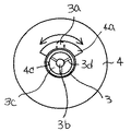
回転軸3は、略円盤形状をしており、この略円盤形状の中央に雄ねじ部3eが突設して形成されている。さらに、この雄ねじ部3eの内側には、上流側に向けてコーン形状の突部3bを形成し、図7に示すように3つのガイド部3dにより、突部3bを回転軸3本体に連結している。そして、ガイド部3d間に流路3cを形成している。なお、突部3bをコーン形状とすることで、通水路15から吐水形態切替ユニット2内への通水がこのコーン形状に沿って流路3cをスムーズに通過するのである。
【0018】
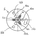
流路切替板6は、図5に示すように、円盤形状をしていて、この円盤の中央に各ガイド部3dに嵌合する嵌合片6aを配置してなり、かつ、散水板5からの通常のシャワーとノズル9からの旋回シャワーを行うために通水される通水穴16a、16bがそれぞれ3つずつ配置されている。なお、通常のシャワーを行うために通水される通水穴の1つを長穴とし、吐水切替時に止水状態を生じないようにしている。(図6(c)を参照)
【0019】
流路切替機構部7は、上面7bを備えかつ底面を備えない筒形状をしており、内部に隔壁7aを形成している。そして、上面7bには、図4に示すようにこの隔壁7aを境にして内側に通水するための通水穴17aを形成し、外側に通水するための通水穴17bを形成している。
【0020】
ノズルユニット2Aは、図12に示すように、ノズルケース10と、ノズル9と、ノズルガイド8とから構成する。そして、このノズルケース10とノズルガイド8を重ね合わせることによって、流入室を形成している。そして、この流入室内にノズル9を収納するとともに、ノズルの先端部9cを開口8aから流入室外部に臨ませている。
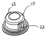
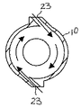
ノズルケース10は、図8乃至10に示すように、上面を備えかつ底面を備えない略筒型形状をしており、側面に細い縦長形状の流入口23を2つ左右対称に備えている。
この流入口23は、図10に示すように、ノズルケース10の内周面に対して接線方向に形成されている。
そして、図13に示すように、この流入口から通水をノズルケース10内に導き、ノズルユニット2A内で通水が旋回するようにしている。特に細い縦長形状の流入口23としているので、ノズルユニット2Aの軸に対して、より均一な旋回流を生じさせやすくすることができる。
なお、通水が旋回すれば、流入口23は必ずしも接線方向に形成しなくともよい。たとえば、流入口23を接線方向以外の方向で側面または上面に斜め方向に形成してもよい。ただし、通水が流入口23から内周面にスムーズに流れて旋回するようにして圧力損失をできる限り抑えるため、この流入口23を内周面に対して接線方向に形成することが好ましい。
また、本実施の形態では、流入口23を軸方向に対して点対称に2つ形成したが、1つでもよい。
【0021】
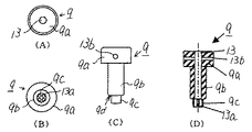
ノズル9は、図11に示すように、略円柱形のノズル本体9bの一端部にこのノズル本体9bの径よりも小さい先端部9cを延設し、他端部にノズル本体9bの径よりも大きい錘部9aを延設して一体成形されている。
そして、このノズル9の軸方向に通水路13が錘部9a側から先端部9c側のノズル本体9bまで1つ形成され、さらに、この通水路13は先端部9cで軸方向に沿って4つの吐水口13aに分岐されている。このように軸方向に沿って通水路13ならびに吐水口13aを形成することで加工しやすいと言える。なお、吐水口13aを4つの場合を例に挙げて説明したが、これに限定されず、複数であればよく、2つ、3つでもよい。
このように通水路13を軸方向に沿って形成することで、ノズルユニット2A内で生じた旋回流の旋回成分をノズル9の通水路13中で軽減させて吐水口13aから吐水させることができる。そのため、吐水の乱れを抑えることができる。なお、図16に示すように、この通水路13内に整流板91aを設けて旋回流の旋回成分を軽減させても良い。
また、錘部9aには側部に孔13bを形成している。この孔13bは、ノズル本体9bに形成してもよい。この孔13bを形成することで、初期の通水によって、ノズル9が斜めに成りやすく、ノズル9の旋回開始を促進することができる。
なお、通水路13に対して、一方の側部にのみ孔13bを形成するのではなく、対向する両方の側部に孔13Bを形成した場合の方が旋回開始を促進することができた。
なお、ノズル9が傾斜している状態で通水するとノズル9の旋回始動が起こりやすい。
そのため、錘部9aをノズル9の軸に対して変心させて傾斜しやすくしてもよい。
また、シャワーヘッド1は、ヘッド部1Aが斜め方向に配置されて使用されるため、このヘッド部1A内に配置されたノズル9自体も斜めに傾いた状態になっていると言えるが、上述するように孔13bなどを形成しておくことで、シャワーヘッド1がどのように配置されても、ノズル9の通水初期の旋回始動を起こしやすくすることができる。
なお、図17に示すように、流入口23を1つとして初期にノズルに当たる旋回流を非対称とすることでも、ノズルを傾斜させることができるので、通水初期の旋回始動を起こしやすくすることができる。
【0022】
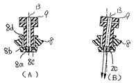
ノズルガイド8は、図14に示すように、中央にノズル9の先端部9cのみを突設する開口8aを形成している。
そして、図14に示すように、ノズル9の先端部9cを開口8aから突設させて、さらに、ノズルガイド8のノズル支持部12にノズル本体9bの端部であるノズル段部9dの一部が当接して首振り可能に構成されているのである。
また、このノズルガイド8の先端部8bには凹部8cが形成されている。そして、ノズル9の先端部9cはこの凹部8c内で旋回可動する。
つまり、図2、図3や図14に示すように、ノズル9の吐水口13の先端は、ノズルガイド8の下面より出ないよう形成している。
そのため、シャワーヘッド1を誤って落下させた場合においても、直接ノズル9に接触しないため、衝撃が和らぎ、損傷を軽減することができる。なお、ばね11も落下による衝撃を吸収する役割を果たす。
また、錘部9aの外形は、ノズルガイド8に形成したノズル9を挿入する側の挿入部8Dの内径よりも大きくしている。このような構成にしているため、たとえば、通水時にシャワーヘッド1を誤って落下させてノズルガイド部8の先端部8bを破損した場合においてもノズル9がノズルガイド部8から飛び出すことがない。
【0023】
散水板5は、通常のシャワーを吐水するための複数の散水孔5aを設けた円盤形状をしており、その外周部に吐水切替操作部4に螺合して取り付けるためのねじ部5cが形成されている。また、散水板5の中央には開口部5bが形成されており、その開口部5bからはノズルガイド8とノズル9の先端部が突出される。
【0024】
では、具体的に吐水形態切替ユニット2の組み立て方法について説明する。
予め、回転軸3と連動するよう位置決めされた状態で回転軸3に流路切替板6を嵌装する。
具体的には、流路切替板6に設けた嵌合片6aを回転軸3のガイド部3dに嵌装させることで固定する。
なお、突部3bの内側の空間にばね11を装着して、このばね11の付勢と流れてくる通水水圧により、流路切替機構部7のOリング面に押し付け水密性を保つようにしている。
【0025】
そして、この流路切替板6を嵌装した回転軸3を吐水切替操作部4に組み付ける。具体的には、吐水切替操作部4の開口4Cへ回転軸3に形成された雄ねじ部3eを突設するように組み込む。
なお、言うまでもないが、回転軸3を吐水切替操作部4に組み付けた後、流路切替板6を固定軸3に組み付けてもよい。
【0026】
次に、流路切替機構部7は、吐水切替操作部4と連動するように位置決めされた状態で、吐水切替操作部4内に嵌装される。
そして、この流露切替機構部7の隔壁7aの内側にノズルユニット2Aを嵌装する。
そして、散水板5は、そのねじ部5cを利用して吐水切替操作部4の端部内側に螺着される。
こうすることで、散水板5の開口部5bからノズルガイド8とノズル9の先端部が突出するように、散水板5で吐水切替操作部4内を覆うことができる。
【0027】
そして、吐水形態切替ユニット2をヘッド部1Aに取付けるため、開口4Cから突設した雄ねじ部3eを、ヘッド部1Aに形成された雌ねじ部1Bに螺合することで、シャワーヘッド1を構成しているのである。
【0028】
なお、吐水切替操作部4は、回転軸3を軸として回転可能に取り付けられている。
つまり、回転軸3と流路切替板6とばね11は、ヘッド部1Aに固定されており、他の部材は吐水切替操作部4に固定されている。
そのため、吐水切替操作部4をヘッド部1Aに対して回転することで、ヘッド部1Aに固定されている流路切替板6に対して流路切替機構部7が回転し、流路切替板6と流路切替機構部7とにそれぞれに設けた通水穴が重なり合ったり、重なり合わなかったりして流路を切り替えるのである。
【0029】
では、吐水切替による通水穴の重なり合い状態を図6に基づき具体的に説明する。
図6(A)は、ノズルユニット2Aに通水してノズル9を旋回させて旋回シャワーを得る場合の通水穴の重なり合いを示す。つまり、流路切替板6の通水穴16aと流路切替機構部7の通水穴17aとが重なり合い、流路切替板6の通水穴16bと流路切替機構部7の通水穴17bとが重なり合っていない状態である。
図6(b)は、散水板5の散水孔5aから通常シャワーを得る場合の通水穴の重なり合いを示す。つまり、流路切替板6の通水穴16bと流路切替機構部7の通水穴17Bとが重なり合い、流路切替板6の通水穴16aと流路切替機構部7の通水穴17aとが重なり合っていない状態である。
さらに、図6(c)は、図6(a)と(b)の切替途中を示す。切替途中に止水状態を形成してしまうと、シャワーホースおよびシャワーヘッド内に静水圧(水道管の給水圧)が掛かってしまい、高い水圧を部材が受けてしまう。そのため、止水状態を形成しないように、1つの通水穴16bを長穴にして、切替途中において、両方の通水穴から通水されるようにしているのである。
なお、吐水切替時の回転範囲を規制するための回転規制手段は、吐水切替操作部4に形成した凹部4aと固定軸3に形成した凸部3aにより形成される。
つまり、図7に示すように、固定軸3に形成した凸部3aが回転する吐水切替操作部4の内側に形成した凹部4aの端部に当たることで、その回転する範囲を規制している。そして、凹部4aの一端部に凸部3aが当接したときに通常のシャワーに切り替わり、また、他端部に凸部3aが当接したときにノズル9からの旋回シャワーに切り替わるのである。
【0030】
次に、ノズル9からの旋回シャワーについて以下で説明する。
まず、シャワーヘッド1の給水口14より供給された湯水は、シャワーヘッド本体1の通水路15を通り吐水形態切替ユニット2内に供給される。
回転軸3内に湯水が通水されると流路切替板6の通水穴16aと流路切替機構部7の通水穴17aが連通し、吐水流室18に湯水が流れ、吐水流室18から、ノズルケース10の流入口23に入り、ノズル9内の通水路13を通り、ノズル9の吐水口13aから吐水される。
【0031】
ノズルケース10の流入口23は、図13に示すように、接線方向(斜め方向)から内部に流入するように形成され、ノズルケース10内に旋回流を引き起こす。
この旋回流の水の勢いにより、ノズル9が、ノズルガイド8のノズル支持部12を軸として、首振り回転をしながら、吐水する。また、錘部9aをノズル本体9bの先端部9cと対向する一端部に一体に配置したことでノズルが安定して旋回しやすい。
この際、ノズルケース10内の湯水が、ノズル9の通水路19だけでなく、ノズルガイド8とノズル9の隙間20よりノズル9に沿って、流れ出す。このノズル9の周りの湯水が潤滑剤となり、ノズルケース10のノズル支持部12とノズル段部9cとの磨耗が減り、耐久性を向上することができる。
【0032】
また、この隙間20からながれでた微量の湯水は、ノズル9の先端部9cが隙間20部分の径と先端の径を略同径に形成していることにより、回転しているノズル9の先端部9cによって飛び散ることなく、逆にノズル9の吐水口13からの吐水に収束して散水される。
【0033】
また、散水孔5aからの通常のシャワーを選択した場合、流路切替板6の通水穴16bは、流路切替機構部7上の通水穴17bと連通し、湯水は、吐水流室21を通って、散水板5の散水孔5aより吐水される。
【0034】
この旋回させて吐水するノズルによって、適度な断続感を得ることができマッサージ効果を得ることができる。
特に、この適度な断続感はノズルの旋回速度をあまり早くしすぎると得られなくなってしまうため、適度な回転数とすることが必要である。
このノズルの回転数は、吐水量、ノズル重量、形状および重心によって左右される。
吐水量を身体にシャワーを浴びたときに快適な所定の量に設定した場合、ノズルの重量や形状重心位置によって回転数が決まってくる。
特に、合成樹脂だけで形成し軽量化するとノズルの回転数が早くなりすぎ、適度な断続感が得られ難くなる。
そのため、上述したノズル9は、金属製の部材から構成するとよい。たとえば、黄銅で形成するとよい。この場合さらに切削加工ができるため、回転数の違う仕様を容易に成形することができると言える。
また、ノズル9は金属部90aをインサートさせた合成樹脂製の部材から構成してもよい。
この場合、図15に示すように、錘部9aの部分に黄銅等からなる金属部90aをインサートし、ノズル9自体をABS樹脂やポリプロピレンなどの合成樹脂材を用いるとよい。
一方、ノズルガイド8に形成したノズル支持部12は、合成樹脂製の部材から構成されている。たとえば、このノズルガイド8は強度が必要なため、ポリアセタールなどを用いるとするとよい。
このようにノズル9を重量のある金属製とすることでノズル9の回転力が増すことができる。さらには、ノズル9とノズル支持部12と別材料とすることで摩擦を低減させることができる。
なお、ノズル9の先端部9cの形状であるが、たとえば、図15(A)に示すように、ノズル本体9b側から先端に向かって径が小さくなるように形成してもよい。このようにすることで、ノズル9とノズル支持部9cとの隙間から流れ出た湯水は、先端部9cに伝わって、吐水口13aからの吐水に収束させることができると言える。
さらに、図15(B)のように先端部9cに螺旋状の溝90cなどを設けておき、この溝90cに伝わって吐水に吐水口13aからの吐水に収束させてもよい。
【0035】
本発明は上述の実施例に限定されること無く種々のシャワーヘッドへの応用が可能であり、浴室やシャワールームでの使用のみならず、例えば、台所用水栓、洗面用水栓、などで用いる引出し自在のシャワーヘッドに用いることができる。
【0036】
【発明の効果】
以上のように構成したことにより、誤って落下させた場合においてもその衝撃を吸収することができるシャワーヘッドを提供することができる。
【図面の簡単な説明】
【図1】本件発明の実施の形態であるシャワーヘッドの断面図を示す。
【図2】図1の吐水切替ユニットの断面図で散水板の通水孔からの通常のシャワーが選択された状態。
【図3】図1の吐水切替ユニットの断面図でノズルからの旋回シャワーが選択された状態。
【図4】流路切替機構部の平面図を示す。
【図5】流路切替板の平面図を示す。
【図6】流路切替の通水穴の重なり合い状態を示す。
【図7】吐水切替操作部と固定軸とにより形成した吐水切替時の回転規制手段を示す。
【図8】ノズルケースの外観図を示す。
【図9】ノズルケースの平面図を示す。
【図10】図9のA−A断面図を示す。
【図11】ノズルを示す。
【図12】ノズルユニットの組み立て方法を示す。
【図13】図12のノズルケースのA−A断面図における通水の流れを示す。
【図14】ノズルガイドに支持されたノズルの状態を示す。
【図15】ノズルの別の実施形態を示す。
【図16】ノズルの通水路に整流板を設けた場合を示す。
【図17】ノズルケースに流入口を1つ形成した場合を示す。
【符号の説明】
1 シャワーヘッド
1A ヘッド部
2 吐水形態切替ユニット
2A ノズルユニット
3 回転軸
4 吐水切替操作部
5 散水板
6 流路切替板
7 流路切替機構部
7a 隔壁
8 ノズルガイド
9 ノズル
10 ノズルケース
11 ばね
12 ノズル支持部
13 吐水口
14 給水口
15 通水路
16a 通水穴
16b 通水穴
17a 通水穴
17b 通水穴
18 吐水流室
20 隙間
21 吐水流室
23 流入口[0001]
TECHNICAL FIELD OF THE INVENTION
The present invention relates to a shower head. More specifically, the present invention relates to a shower head having a water discharge switching mechanism capable of switching a water discharge mode and a shower head having a nozzle that discharges water while turning.
[0002]
[Prior art]
Conventional shower heads include a shower head having a water discharge switching mechanism capable of switching a water discharge mode. (See, for example, Patent Document 1)
Further, in the conventional shower head, there is a shower head having a nozzle which is turned and discharged. (See, for example, Patent Document 2)
[0003]
[Patent Document 1]
JP-A-54-127615 [Patent Document 2]
Japanese Unexamined Patent Publication No. 2002-520156
[Problems to be solved by the invention]
However, since these shower heads are provided with the water discharge switching mechanism, the head portion becomes heavy. Therefore, if the user accidentally drops the shower head, the head may collide with the floor and be damaged. In particular, when the shower head is provided with a nozzle that swirls and discharges water, the impact of the drop may affect the swirlability.
[0005]
Therefore, an object of the present invention is to provide a shower head that can absorb the impact of an accidental drop in order to solve the above-mentioned problems.
[0006]
[Means for Solving the Problems]
According to the first aspect of the present invention, there is provided a shower head including a water discharge mode switching unit capable of switching water discharge to a plurality of different water discharge modes, wherein the water discharge mode switching unit is fixed to a head portion of the shower head. A rotating shaft, a flow path switching plate locked to the rotating shaft, a water discharge switching operation section rotatably provided with respect to the shower head, and a flow path switching mechanism rotating in conjunction with the water discharge switching operation section. At least, the flow path switching plate and the flow path switching mechanism are formed with water holes in the inner and outer peripheral portions, respectively, and by rotating the water discharge switching operation section, the fixed flow path switching plate The water passage hole at the inner periphery of the passage and the water passage hole at the inner periphery of the flow path switching mechanism are communicated with each other, or the water passage hole at the outer periphery of the fixed flow path switching plate and the flow path switching mechanism Switch the water discharge by communicating with the water hole on the outer periphery of A spring is provided between the fixed shaft and the flow path switching plate, and the elastic force of the spring presses the flow path switching plate against the flow path switching mechanism, and the head section of the shower head. The shower head is characterized in that an elastic force of a spring is urged in a direction in which the water discharge mode switching unit moves away from the shower head.
[0007]
Thereby, when the water discharge mode switching unit collides with the floor when the shower head is dropped, the weight of the shower head body can be absorbed by the elastic force of the spring. When the shower head body collides with the floor, the weight of the water discharge mode switching unit can be absorbed by the elastic force of the spring. Therefore, the possibility that the shower head is damaged by the impact due to the drop can be reduced.
[0008]
According to a second aspect of the present invention, there is provided a water discharge mode in which water is discharged from a nozzle turned into one of the water discharge modes, and a nozzle unit for generating the water discharge mode is disposed downstream of the flow path switching mechanism. This nozzle unit is composed of an inflow chamber into which the hot water flows, and a nozzle for discharging the hot water flowing into the inflow chamber, and further, the hot water flowing into the inflow chamber turns along the inner peripheral wall surface in the inflow chamber. An inflow port is formed in the inflow chamber so as to cause a flow, and the nozzle has a nozzle body and a tip portion having a smaller diameter than the nozzle body, and this tip portion is exposed from the opening of the inflow chamber to the outside. The tip of the nozzle is formed so as not to protrude from the outer surface of the shower head, the nozzle body is supported by a nozzle support portion of the inflow chamber, and the nozzle discharges water while swirling by swirling flow. In one And the mounting of the shower head.
[0009]
Accordingly, in the shower head including the swirling nozzle, the nozzle tip does not protrude from the outer surface of the shower head, so that the possibility that the nozzle itself collides with the floor when dropped can be reduced. Therefore, there is no possibility that the nozzle is deformed and the turning performance is reduced.
[0010]
According to a third aspect of the present invention, there is provided a water discharge device including an inflow chamber into which hot water flows, and a nozzle for discharging the hot water flowing into the inflow chamber, wherein the inflow chamber includes a nozzle case and a nozzle guide. An inlet is formed in the inflow chamber so that the hot and cold water flowing into the inflow chamber causes a swirling flow along the inner peripheral wall surface in the inflow chamber. Further, the nozzle is provided at the nozzle body and at one end of the nozzle body. An inflow chamber having a tip portion having a smaller diameter than the nozzle body and a weight portion having a larger diameter than the nozzle body provided at the other end of the nozzle body, being larger than the outer shape of the nozzle body and smaller than the outer shape of the weight portion. The nozzle is inserted into the insertion section formed at the end, and the tip of the nozzle is exposed to the outside from the opening of the inflow chamber communicating with the insertion section, and the nozzle body is supported by the nozzle support section of the inflow chamber, and swiveled. The nozzle is swirled by the flow to discharge Was the shower head, characterized in that the.
[0011]
Thus, even if the nozzle support portion is broken when the shower head is dropped, the weight portion is not caught by the insertion portion and the nozzle itself does not jump out of the shower head.
[0012]
According to a fourth aspect of the present invention, the tip of the nozzle is formed so as not to protrude from the outer surface of the shower head.
[0013]
Thereby, since the nozzle tip does not protrude from the outer surface of the shower head, the possibility that the nozzle itself collides with the floor when dropped can be reduced. Therefore, there is no possibility that the nozzle is deformed and the turning performance is reduced.
[0014]
BEST MODE FOR CARRYING OUT THE INVENTION
Hereinafter, the present invention will be described more specifically with reference to the drawings.
1 to 3 show an embodiment of a
The
[0015]
The
As shown in FIG. 2, the water discharge mode switching unit 2 has an outer surface composed of a rotating
[0016]
Now, each component of the water discharge mode switching unit 2 will be specifically described below.
The water discharge switching
[0017]
The
[0018]
As shown in FIG. 5, the flow
[0019]
The
[0020]
The
As shown in FIGS. 8 to 10, the
The
Then, as shown in FIG. 13, the water flow is guided from the inflow port into the
In addition, if water flow turns, the
In the present embodiment, two
[0021]
As shown in FIG. 11, the
Then, one
By forming the
A hole 13b is formed on the side of the
In addition, the hole 13b was formed only on one side of the
If water is supplied while the
Therefore, the
Further, since the
In addition, as shown in FIG. 17, the nozzle can be tilted even if the swirling flow initially hitting the nozzle is asymmetrical with one
[0022]
As shown in FIG. 14, the
Then, as shown in FIG. 14, the tip 9c of the
A recess 8c is formed at the tip 8b of the
That is, as shown in FIGS. 2, 3, and 14, the tip of the
Therefore, even when the
The outer shape of the
[0023]
The
[0024]
Now, a method of assembling the water discharge mode switching unit 2 will be specifically described.
The flow
Specifically, the
A spring 11 is mounted in the space inside the protruding
[0025]
Then, the
Needless to say, the flow
[0026]
Next, the channel
Then, the
Then, the sprinkling
By doing so, the inside of the water discharge switching
[0027]
Then, in order to attach the water discharge form switching unit 2 to the
[0028]
In addition, the water discharge switching
That is, the
Therefore, by rotating the water discharge switching
[0029]
Now, the overlapping state of the water holes due to the water discharge switching will be specifically described with reference to FIG.
FIG. 6A shows the overlapping of water holes when water is passed through the
FIG. 6B shows the overlapping of water holes when a normal shower is obtained from the water holes 5 a of the
Further, FIG. 6C shows a state during the switching between FIGS. 6A and 6B. If the water stop state is formed during the switching, a hydrostatic pressure (water supply pressure of a water pipe) is applied to the inside of the shower hose and the shower head, and the member receives a high water pressure. For this reason, one
The rotation restricting means for restricting the rotation range at the time of water discharge switching is formed by a concave portion 4 a formed on the water discharge switching
That is, as shown in FIG. 7, the rotation range is restricted by the protrusion 3 a formed on the fixed
[0030]
Next, the swirling shower from the
First, hot water supplied from the
When hot or cold water is passed through the
[0031]
As shown in FIG. 13, the
Due to the force of the water of the swirling flow, the
At this time, the hot water in the
[0032]
Also, a small amount of hot and cold water flowing from the
[0033]
When the normal shower from the water sprinkling hole 5a is selected, the
[0034]
With this nozzle that is turned to discharge water, an appropriate intermittent feeling can be obtained and a massage effect can be obtained.
In particular, this moderate intermittent feeling cannot be obtained if the swirling speed of the nozzle is too high, so it is necessary to set the rotational speed to an appropriate value.
The number of rotations of the nozzle depends on the amount of water discharged, the weight of the nozzle, the shape, and the center of gravity.
When the amount of water discharged is set to a predetermined amount that is comfortable when the body is showered, the number of rotations is determined by the weight of the nozzle and the position of the center of gravity of the shape.
In particular, if it is formed only of a synthetic resin to reduce the weight, the number of rotations of the nozzle becomes too fast, and it becomes difficult to obtain an appropriate intermittent feeling.
Therefore, the above-described
Further, the
In this case, as shown in FIG. 15, a metal portion 90a made of brass or the like may be inserted into the
On the other hand, the
In this way, by making the
The shape of the tip 9c of the
Further, as shown in FIG. 15 (B), a spiral groove 90c or the like may be provided in the distal end portion 9c, and the water may be transmitted to the groove 90c to converge the water discharged from the water discharge port 13a.
[0035]
The present invention can be applied to various shower heads without being limited to the above-described embodiment, and can be used not only in a bathroom or a shower room, but also, for example, a drawer used in a kitchen faucet, a wash faucet, and the like. It can be used for a free shower head.
[0036]
【The invention's effect】
With the above-described configuration, it is possible to provide a shower head that can absorb the impact even when it is accidentally dropped.
[Brief description of the drawings]
FIG. 1 is a sectional view of a shower head according to an embodiment of the present invention.
FIG. 2 is a cross-sectional view of the water discharge switching unit in FIG. 1 in a state where a normal shower from a water hole of a sprinkling plate is selected.
FIG. 3 is a cross-sectional view of the water discharge switching unit in FIG. 1 in a state where a swirling shower from a nozzle is selected.
FIG. 4 is a plan view of a flow path switching mechanism.
FIG. 5 is a plan view of a flow path switching plate.
FIG. 6 shows an overlapping state of water passage holes for flow path switching.
FIG. 7 shows a rotation restricting means at the time of water discharge switching formed by a water discharge switching operation section and a fixed shaft.
FIG. 8 shows an external view of a nozzle case.
FIG. 9 shows a plan view of a nozzle case.
FIG. 10 is a sectional view taken along line AA of FIG. 9;
FIG. 11 shows a nozzle.
FIG. 12 shows a method of assembling the nozzle unit.
FIG. 13 shows a flow of water flow in an AA cross-sectional view of the nozzle case of FIG.
FIG. 14 shows a state of a nozzle supported by a nozzle guide.
FIG. 15 shows another embodiment of a nozzle.
FIG. 16 shows a case where a flow straightening plate is provided in a water passage of a nozzle.
FIG. 17 shows a case where one inflow port is formed in the nozzle case.
[Explanation of symbols]
DESCRIPTION OF
Claims (4)
この吐水形態切替ユニットには、シャワーヘッドのヘッド部に対して固定される回転軸とこの回転軸に係止される流路切替板と、シャワーヘッドに対して回転自在に設けられる吐水切替操作部とこの吐水切替操作部と連動して回転する流路切替機構部とから少なくとも構成されており、
流路切替板と流路切替機構部との内周部と外周部に通水穴をそれぞれ形成し、吐水切替操作部を回転させることで、固定された流路切替板の内周部の通水穴と流路切替機構部の内周部の通水穴とを連通させるか、もしくは、固定された流路切替板の外周部の通水穴と流路切替機構部の外周部の通水穴とを連通させて吐水を切り替えてなり、
この固定軸と流路切替板との間には、ばねを設け、このばねの弾性力によって、流路切替板を流路切替機構部に押し当ててなるとともに、シャワーヘッドのヘッド部に対して吐水形態切替ユニットが離れる方向にばねの弾性力が付勢していることを特徴とするシャワーヘッド。A shower head including a water discharge mode switching unit that can switch water discharge to a plurality of different water discharge modes,
The water discharge mode switching unit includes a rotating shaft fixed to a head portion of the shower head, a flow path switching plate locked to the rotating shaft, and a water discharging switching operation unit rotatably provided with respect to the shower head. And a flow path switching mechanism that rotates in conjunction with the water discharge switching operation section,
Water holes are formed in the inner and outer peripheral portions of the flow path switching plate and the flow path switching mechanism, respectively, and by rotating the water discharge switching operation section, the inner peripheral portion of the fixed flow path switching plate is opened. The water hole communicates with the water passage hole on the inner periphery of the passage switching mechanism, or the water passage on the outer periphery of the fixed passage switching plate and the passage of water on the outer periphery of the passage switching mechanism. By switching the water discharge by communicating with the hole,
A spring is provided between the fixed shaft and the flow path switching plate, and the elastic force of the spring presses the flow path switching plate against the flow path switching mechanism, and at the same time, presses against the head of the shower head. A shower head, wherein an elastic force of a spring is urged in a direction in which the water discharge mode switching unit moves away.
このノズルユニットは、湯水が流入する流入室と、流入室内に流入した湯水を吐水するノズルとで構成されており、さらに流入室内に流入した湯水が流入室内の内周壁面に沿って旋回流を起こすように流入室に流入口を形成し、
かつ、ノズルは、ノズル本体とノズル本体よりも小径の先端部とを有し、
この先端部を流入室の開口部から外部に臨ませるとともに、ノズルの先端部が、シャワーヘッド外面より出ないように形成し、さらにノズル本体を流入室のノズル支持部にて支持し、旋回流によりノズルが旋回しながら吐水することを特徴とする請求項1に記載のシャワーヘッド。A water discharge form in which water is discharged from a nozzle turned into one of the water discharge forms, and a nozzle unit for generating the water discharge form is arranged downstream of the flow path switching mechanism;
The nozzle unit includes an inflow chamber into which the hot water flows, and a nozzle that discharges the hot water flowing into the inflow chamber, and further, the hot water flowing into the inflow chamber forms a swirling flow along an inner peripheral wall surface in the inflow chamber. Form an inflow port in the inflow chamber to wake up,
And the nozzle has a nozzle body and a tip portion having a smaller diameter than the nozzle body,
This tip is exposed from the opening of the inflow chamber to the outside, and the tip of the nozzle is formed so as not to protrude from the outer surface of the shower head. The shower head according to claim 1, wherein the nozzle discharges water while turning.
流入室は、ノズルケースとノズルガイドから構成されており、
流入室内に流入した湯水が流入室内の内周壁面に沿って旋回流を起こすように流入室に流入口を形成し、
さらに、ノズルは、ノズル本体と、このノズル本体の一端に設けたノズル本体よりも小径の先端部と、このノズル本体の他端に設けたノズル本体よりも大径の錘部とを有し、
ノズル本体の外形よりも大きく、錘部の外形よりも小さい流入室内に形成した挿入部にノズルを挿入して、ノズルの先端部を挿入部に連通している流入室の開口部から外部に臨ませてノズル本体を流入室のノズル支持部にて支持し、旋回流によりノズルが旋回しながら吐水することを特徴とするシャワーヘッド。An inflow chamber into which hot water flows, and a water discharge device incorporating a nozzle for discharging hot water flowing into the inflow chamber,
The inflow chamber is composed of a nozzle case and a nozzle guide,
Forming an inflow port in the inflow chamber so that the hot water flowing into the inflow chamber causes a swirling flow along the inner peripheral wall surface in the inflow chamber,
Further, the nozzle has a nozzle body, a tip portion having a smaller diameter than the nozzle body provided at one end of the nozzle body, and a weight portion having a larger diameter than the nozzle body provided at the other end of the nozzle body,
The nozzle is inserted into an insertion portion formed in the inflow chamber that is larger than the outer shape of the nozzle body and smaller than the outer shape of the weight portion, and the tip of the nozzle faces the outside through the opening of the inflow chamber communicating with the insertion portion. In addition, a shower head characterized in that a nozzle body is supported by a nozzle support portion of an inflow chamber, and water is discharged while a nozzle is swirled by a swirling flow.
Priority Applications (2)
| Application Number | Priority Date | Filing Date | Title |
|---|---|---|---|
| JP2002268139A JP2004105791A (en) | 2002-09-13 | 2002-09-13 | Showerhead |
| TW92125214A TWI260996B (en) | 2002-09-13 | 2003-09-12 | Spraying device |
Applications Claiming Priority (1)
| Application Number | Priority Date | Filing Date | Title |
|---|---|---|---|
| JP2002268139A JP2004105791A (en) | 2002-09-13 | 2002-09-13 | Showerhead |
Publications (2)
| Publication Number | Publication Date |
|---|---|
| JP2004105791A true JP2004105791A (en) | 2004-04-08 |
| JP2004105791A5 JP2004105791A5 (en) | 2005-09-02 |
Family
ID=32266440
Family Applications (1)
| Application Number | Title | Priority Date | Filing Date |
|---|---|---|---|
| JP2002268139A Withdrawn JP2004105791A (en) | 2002-09-13 | 2002-09-13 | Showerhead |
Country Status (1)
| Country | Link |
|---|---|
| JP (1) | JP2004105791A (en) |
Cited By (12)
| Publication number | Priority date | Publication date | Assignee | Title |
|---|---|---|---|---|
| CN101875030A (en) * | 2010-05-19 | 2010-11-03 | 宁波市镇海中正园艺工具有限公司 | Sprinkler with self-generating light source |
| WO2012092834A1 (en) * | 2011-01-05 | 2012-07-12 | 厦门松霖科技有限公司 | Showerhead |
| WO2015192728A1 (en) * | 2014-06-19 | 2015-12-23 | 周华松 | Water outlet apparatus and method for controlling same |
| WO2016106693A1 (en) * | 2014-12-31 | 2016-07-07 | 欣宇科技(福建)有限公司 | Functional switching structure with push-button switch of shower head |
| US20180297042A1 (en) * | 2017-04-17 | 2018-10-18 | Fujian Xihe Sanitary Ware Technology Co., Ltd. | Centrifugal water spray structure and showerhead including the same |
| US10328581B2 (en) | 2016-04-29 | 2019-06-25 | Industrial Technology Research Institute | Method and device for robotic direct lead-through teaching |
| JP2021065710A (en) * | 2019-10-25 | 2021-04-30 | 厦門松霖科技股▲ふん▼有限公司 | Water discharge device discharging different water splashes from the same outlet |
| JP2021133293A (en) * | 2020-02-26 | 2021-09-13 | 源美股▲分▼有限公司 | Rotor nozzle structure and sprinkler system |
| CN114210476A (en) * | 2021-12-20 | 2022-03-22 | 江西三江精密针车有限公司 | Bathroom shower nozzle |
| WO2022062075A1 (en) * | 2020-09-24 | 2022-03-31 | 福建欣宇卫浴科技股份有限公司 | Automatic return shower head and use method |
| CN115318458A (en) * | 2022-08-17 | 2022-11-11 | 厦门一岂科技有限公司 | Swing water outlet mechanism and shower head with same |
| US11944989B2 (en) | 2020-09-24 | 2024-04-02 | Sinyu Technology (Fujian) Co., Ltd. | Automatic return shower head and use method thereof |
-
2002
- 2002-09-13 JP JP2002268139A patent/JP2004105791A/en not_active Withdrawn
Cited By (18)
| Publication number | Priority date | Publication date | Assignee | Title |
|---|---|---|---|---|
| CN101875030A (en) * | 2010-05-19 | 2010-11-03 | 宁波市镇海中正园艺工具有限公司 | Sprinkler with self-generating light source |
| CN101875030B (en) * | 2010-05-19 | 2012-03-28 | 宁波市镇海中正园艺工具有限公司 | Sprinkler with self-generating light source |
| WO2012092834A1 (en) * | 2011-01-05 | 2012-07-12 | 厦门松霖科技有限公司 | Showerhead |
| CN102580869A (en) * | 2011-01-05 | 2012-07-18 | 厦门松霖科技有限公司 | Sprinkler |
| US9283575B2 (en) | 2011-01-05 | 2016-03-15 | Xiamen Solex High-Tech Industries Co., Ltd. | Shower |
| WO2015192728A1 (en) * | 2014-06-19 | 2015-12-23 | 周华松 | Water outlet apparatus and method for controlling same |
| WO2016106693A1 (en) * | 2014-12-31 | 2016-07-07 | 欣宇科技(福建)有限公司 | Functional switching structure with push-button switch of shower head |
| US10328581B2 (en) | 2016-04-29 | 2019-06-25 | Industrial Technology Research Institute | Method and device for robotic direct lead-through teaching |
| US20180297042A1 (en) * | 2017-04-17 | 2018-10-18 | Fujian Xihe Sanitary Ware Technology Co., Ltd. | Centrifugal water spray structure and showerhead including the same |
| US10478838B2 (en) * | 2017-04-17 | 2019-11-19 | Fujian Xihe Sanitary Ware Technology., Ltd. | Centrifugal water spray structure and showerhead including the same |
| JP2021065710A (en) * | 2019-10-25 | 2021-04-30 | 厦門松霖科技股▲ふん▼有限公司 | Water discharge device discharging different water splashes from the same outlet |
| JP7165708B2 (en) | 2019-10-25 | 2022-11-04 | 厦門松霖科技股▲ふん▼有限公司 | Water discharge device that can produce different sprays from the same outlet |
| JP2021133293A (en) * | 2020-02-26 | 2021-09-13 | 源美股▲分▼有限公司 | Rotor nozzle structure and sprinkler system |
| WO2022062075A1 (en) * | 2020-09-24 | 2022-03-31 | 福建欣宇卫浴科技股份有限公司 | Automatic return shower head and use method |
| US11944989B2 (en) | 2020-09-24 | 2024-04-02 | Sinyu Technology (Fujian) Co., Ltd. | Automatic return shower head and use method thereof |
| CN114210476A (en) * | 2021-12-20 | 2022-03-22 | 江西三江精密针车有限公司 | Bathroom shower nozzle |
| CN114210476B (en) * | 2021-12-20 | 2022-12-23 | 江西三江精密针车有限公司 | Bathroom shower nozzle |
| CN115318458A (en) * | 2022-08-17 | 2022-11-11 | 厦门一岂科技有限公司 | Swing water outlet mechanism and shower head with same |
Similar Documents
| Publication | Publication Date | Title |
|---|---|---|
| CN203342966U (en) | Spray head assembly used for faucet | |
| CN107995879B (en) | Atomizing nozzle | |
| TW552161B (en) | Multiple discharge shower head with revolving nozzle | |
| JP2004105791A (en) | Showerhead | |
| US7937784B2 (en) | Parent-child showerhead | |
| JP5891527B2 (en) | Shower water discharge device | |
| TW201242669A (en) | Device for spraying a pressurized liquid | |
| CN113117909B (en) | Water outlet device and kitchen shower head | |
| KR101337696B1 (en) | Shower Head With double Shower Face Plate | |
| JP2022013839A (en) | shower head | |
| JP2004105788A (en) | Water delivery device | |
| JP2004105790A (en) | Water delivery device | |
| JP2004105789A (en) | Water delivery device | |
| JP2013162985A (en) | Shower water discharging device | |
| JP2004154732A (en) | Spouting device | |
| US20240001377A1 (en) | Water saving nozzle and shower head comprising such nozzle | |
| KR102331869B1 (en) | inter-lock type device of shower easily replacing head part | |
| KR200445783Y1 (en) | A Shower Flag | |
| TWI260996B (en) | Spraying device | |
| JP2011173081A (en) | Water discharge device | |
| JP2769014B2 (en) | Spout | |
| JP2003000463A (en) | Mist shower device | |
| JP2702568B2 (en) | Foam spout | |
| KR200261310Y1 (en) | Vibration Shower Head | |
| JP7008771B2 (en) | Water discharge structure that can emit fine and soft atomized granular water, shower head and shower head for kitchen |
Legal Events
| Date | Code | Title | Description |
|---|---|---|---|
| A521 | Written amendment |
Free format text: JAPANESE INTERMEDIATE CODE: A523 Effective date: 20050309 |
|
| A621 | Written request for application examination |
Free format text: JAPANESE INTERMEDIATE CODE: A621 Effective date: 20050309 |
|
| A761 | Written withdrawal of application |
Free format text: JAPANESE INTERMEDIATE CODE: A761 Effective date: 20070531 |