JP2004104635A - Image processing device - Google Patents
Image processing device Download PDFInfo
- Publication number
- JP2004104635A JP2004104635A JP2002266317A JP2002266317A JP2004104635A JP 2004104635 A JP2004104635 A JP 2004104635A JP 2002266317 A JP2002266317 A JP 2002266317A JP 2002266317 A JP2002266317 A JP 2002266317A JP 2004104635 A JP2004104635 A JP 2004104635A
- Authority
- JP
- Japan
- Prior art keywords
- target pixel
- density
- pixel
- edge enhancement
- character
- Prior art date
- Legal status (The legal status is an assumption and is not a legal conclusion. Google has not performed a legal analysis and makes no representation as to the accuracy of the status listed.)
- Granted
Links
Images


Classifications
-
- G—PHYSICS
- G06—COMPUTING OR CALCULATING; COUNTING
- G06T—IMAGE DATA PROCESSING OR GENERATION, IN GENERAL
- G06T5/00—Image enhancement or restoration
- G06T5/73—Deblurring; Sharpening
-
- G—PHYSICS
- G06—COMPUTING OR CALCULATING; COUNTING
- G06T—IMAGE DATA PROCESSING OR GENERATION, IN GENERAL
- G06T5/00—Image enhancement or restoration
- G06T5/20—Image enhancement or restoration using local operators
-
- G—PHYSICS
- G06—COMPUTING OR CALCULATING; COUNTING
- G06T—IMAGE DATA PROCESSING OR GENERATION, IN GENERAL
- G06T2207/00—Indexing scheme for image analysis or image enhancement
- G06T2207/10—Image acquisition modality
- G06T2207/10004—Still image; Photographic image
- G06T2207/10008—Still image; Photographic image from scanner, fax or copier
-
- G—PHYSICS
- G06—COMPUTING OR CALCULATING; COUNTING
- G06T—IMAGE DATA PROCESSING OR GENERATION, IN GENERAL
- G06T2207/00—Indexing scheme for image analysis or image enhancement
- G06T2207/20—Special algorithmic details
- G06T2207/20004—Adaptive image processing
- G06T2207/20012—Locally adaptive
-
- G—PHYSICS
- G06—COMPUTING OR CALCULATING; COUNTING
- G06T—IMAGE DATA PROCESSING OR GENERATION, IN GENERAL
- G06T2207/00—Indexing scheme for image analysis or image enhancement
- G06T2207/20—Special algorithmic details
- G06T2207/20172—Image enhancement details
- G06T2207/20192—Edge enhancement; Edge preservation
-
- G—PHYSICS
- G06—COMPUTING OR CALCULATING; COUNTING
- G06T—IMAGE DATA PROCESSING OR GENERATION, IN GENERAL
- G06T2207/00—Indexing scheme for image analysis or image enhancement
- G06T2207/30—Subject of image; Context of image processing
- G06T2207/30176—Document
Landscapes
- Physics & Mathematics (AREA)
- General Physics & Mathematics (AREA)
- Engineering & Computer Science (AREA)
- Theoretical Computer Science (AREA)
- Facsimile Image Signal Circuits (AREA)
- Image Processing (AREA)
Abstract
【課題】文字が記録された原稿を読み取って得られた文字画像情報における所定の注目画素がエッジ強調処理を施す対象である対象画素であるか否かを判別し、その対象画素にエッジ強調処理を施す画像処理装置において、原稿の輪郭が出力されることなく、かつ小ポイント文字を鮮明に出力することができるエッジ強調処理を上記文字画像情報に施す。
【解決手段】濃度判別部12において注目画素の濃度が、原稿の輪郭部分の下地の濃度よりも高く文字を構成する線のうち最も細い線の濃度以下の所定の第1の閾値以上、かつ文字を構成する線のうち最も細い線の濃度以上の第2の閾値以下の場合にその注目画素を濃度対象画素と判別し、その濃度対象画素が細線画像の一部を構成する細線画素であるか否かを判別し、濃度対象画素かつ細線画素と判別された注目画素を対象画素と判別し、その対象画素に小ポイント文字が鮮明に出力されるのに十分な強調度のエッジ強調処理を施す。
【選択図】 図1An object of the present invention is to determine whether a predetermined pixel of interest in character image information obtained by reading a document on which characters are recorded is a target pixel to be subjected to edge enhancement processing, and to perform edge enhancement processing on the target pixel. In the image processing apparatus, the character image information is subjected to edge emphasis processing capable of outputting small point characters clearly without outputting the outline of the document.
The density of a target pixel is higher than a density of a background of an outline portion of a document, is equal to or higher than a predetermined first threshold value equal to or lower than the density of a thinnest line among characters forming a character, and is higher than a density of a character. Is determined to be a density target pixel when the density is equal to or higher than the second threshold value which is equal to or higher than the density of the thinnest line, and whether the density target pixel is a thin line pixel forming a part of the thin line image Is determined, the target pixel determined as a density target pixel and a thin line pixel is determined as a target pixel, and edge enhancement processing is performed on the target pixel with a sufficient degree of enhancement to clearly output a small point character. .
[Selection diagram] Fig. 1
Description
【0001】
【発明の属する技術分野】
本発明は、文字が記録された原稿を読み取って得られた文字画像情報における所定の注目画素がエッジ強調処理を施す対象である対象画素であるか否かを判別し、該対象画素にエッジ強調処理を施す画像処理装置に関するものである。
【0002】
【従来の技術】
従来より、文字が記録された原稿をスキャナなどにより読み取って文字画像情報として得、この文字画像情報における所定の注目画素がエッジ強調処理を施す対象である対象画素であるか否かを判別し、該対象画素にエッジ強調処理を施す画像処理の技術が提案されている。特に、文字の輪郭に応じたエッジ画素を上記対象画素とし、そのエッジ画素にエッジ強調処理を施すことにより、上記文字画像情報に基づいて文字画像を所定の記録媒体に出力した際、該文字画像をより鮮明に出力することができる種々の技術が提案されている。
【0003】
そして、上記のようにエッジ画素にエッジ強調処理を施す際には、まず、エッジ画素を判別する必要があるが、特許文献1には、上記文字画像情報における所定の注目画素について、注目画素とその周辺画素との濃度差分量を求め、この濃度差分量が閾値以上であった場合に上記注目画素をエッジ画素と判別する方法が提案されている。
【0004】
【特許文献1】
特開平10−240929号公報
【0005】
【特許文献2】
特許3115065号公報
【0006】
【発明が解決しようとする課題】
しかしながら、大きいポイントの文字を読み取った場合における文字画像情報における画素濃度と小さいポイントの文字を読み取った場合における文字画像情報における画素濃度は、図10に示すような関係であり、小ポイント文字に応じた文字画像情報における画素の濃度差の方が大ポイント文字に応じた文字画像情報における画素の濃度差のよりも小さい(なお、図10は所定の文字の一部をスキャナなどにより主走査方向に読み取ったときに出力される画素データの濃度を模式的に示したものであり、山部が文字部の濃度を谷部が文字部分における下地部の濃度を示す)。したがって、特許文献1に記載されているような濃度差分量が所定の閾値以上であるか否かによりエッジ画素であるか否かを判別する方法では、エッジ強調が必要な小ポイント文字の輪郭部分の画素をエッジ強調するため小ポイント文字の上記濃度差より小さい閾値を設定する必要があるが、上述のように小ポイント文字の上記濃度差は小さいことから、原稿の輪郭部分の下地の画素の濃度と原稿外の濃度との差が小ポイント文字の濃度差よりも大きくなる場合が存在し、その場合、小ポイント文字の輪郭部分の画素にエッジ強調処理をかけようとすると原稿の輪郭部分の画素にもエッジ強調処理がかかり、原稿のエッジの線が出力されてしまうという問題が生じる。
【0007】
また、特許文献2においては、小ポイント文字に応じた文字画像情報における画素の濃度差が比較的小さいことを考慮し、小ポイント文字を読み取った文字画像情報における小ポイント文字の輪郭部分の画素の濃度が中間濃度であることが多いことから、注目画素の濃度が中間濃度である場合には、上記濃度差の閾値をある程度低い閾値とし、注目画素の濃度が中間濃度でない場合には、通常の閾値を用いてエッジ画素であるか否かを判別する方法が提案されている。しかしながら、上記特許文献2に記載の判別方法においては、上記中間濃度の設定の際に原稿の輪郭部分の下地の濃度は全く考慮されていないため、小ポイント文字の輪郭部分の画素と原稿の輪郭部分の画素とを区別することができない場合がある。
【0008】
また、原稿の輪郭が出力されない程度の強調度のエッジ強調処理をエッジ画素に施すようにすることも可能であるが、そうすると小ポイントの文字を鮮明に出力することが困難となる。
【0009】
本発明は、上記のような事情に鑑み、上記のような小ポイント文字を含む文字画像情報について、原稿の輪郭が出力されることなく、かつ小ポイント文字を鮮明に出力することができるようなエッジ強調処理を上記文字画像情報に施すことができる画像処理装置を提供することを目的とするものである。
【0010】
【課題を解決するための手段】
本発明の画像処理装置は、文字が記録された原稿を読み取って得られた文字画像情報における所定の注目画素がエッジ強調処理を施す対象である対象画素であるか否かを判別する対象画素判別手段を有し、その対象画素判別手段により対象画素と判別された注目画素にエッジ強調処理を施す画像処理装置において、エッジ画素判別手段が、注目画素の濃度が前記原稿の輪郭部分の下地の濃度よりも高く前記文字を構成する線のうち最も細い線の濃度以下の所定の第1の閾値以上かつ文字を構成する線のうち最も細い線の濃度以上の所定の第2の閾値以下の場合に注目画素を濃度対象画素と判別する濃度判別部と、注目画素が細線画像の一部を構成する細線画素であるか否かを判別する細線画像判別部とを有し、濃度判別部において濃度対象画素と判別されるとともに、細線画像判別部において細線画素と判別された注目画素を対象画素と判別するものであることを特徴とする。
【0011】
ここで、上記「所定の注目画素」とは、上記文字画像情報において任意に注目した画素のことを意味する。
【0012】
また、上記「エッジ強調処理」としては、たとえば、ラプラシアンを用いたエッジ強調処理があるが、これに限らず、各種のエッジ強調処理を用いることができる。
【0013】
また、上記「第2の閾値」は、上記文字を構成する線のうち最も細い線の濃度以上であれば如何なる値でもよく、たとえば、文字を構成する線の最大濃度の値とし、注目画素の濃度が上記「第1の閾値」以上の場合は全てその注目画素を濃度対象画素とするようにしてもよい。
【0014】
また、上記「細線画像」とは、たとえば、上記文字画像情報において1画素または数画素の幅で所定の方向に延びた画像のことを意味するが、上記幅についてはエッジ強調処理の必要性に応じて任意に決定することができる。
【0015】
また、上記画像処理装置においては、対象画素判別手段により対象画素と判別されなかった注目画素を非対象画素とし、その非対象画素にエッジ強調処理よりも弱い強調度の弱エッジ強調処理を施すようにすることができる。
【0016】
また、上記画像処理装置においては、対象画素判別手段により対象画素と判別されなかった注目画素を非対象画素とし、その非対象画素とその非対象画素に隣接する周辺画素との濃度差分量を算出する濃度差分量算出手段を有し、その濃度差分量算出手段により算出された濃度差分量が所定の第3の閾値以上である場合には、非対象画素にエッジ強調処理よりも弱い強調度の弱エッジ強調処理を施し、濃度差分量が所定の閾値よりも小さい場合には、非対象画素には弱エッジ強調処理を施さないようにすることができる。
【0017】
【発明の効果】
本発明の画像処理装置によれば、濃度判別部において濃度対象画素と判別されるとともに、細線画像判別部において細線画素と判別された注目画素を対象画素と判別してエッジ強調処理を施すようにしたので、エッジ強調処理を施す小ポイント文字を含む文字画像情報について、原稿の輪郭が出力されることなく、かつ小ポイント文字を鮮明に出力することができるようなエッジ強調処理を施すことができる。また、細線画素か否かを判別するようにしたので、たとえば、原稿の輪郭部分における注目画素であるにもかかわらず、原稿の輪郭部分の下地の濃度の多少の変化により予め設定した第1の閾値以上となり、濃度対象画素と判別されてしまったような注目画素についても、細線画像判別部において排除し、エッジ強調処理が施されないようにすることができる。また、細線画素のみにエッジ強調処理を施すようにしたので、細線画像以外の部分に無駄なエッジ強調処理を施すことを回避することができる。
【0018】
また、上記画像処理装置において、対象画素判別手段により対象画素と判別されなかった非対象画素にエッジ強調処理よりも弱い強調度の弱エッジ強調処理を施すようにした場合には、たとえば、文字画像情報を得る際に使用したレンズが低価格で鮮鋭度の低い文字画像情報しか得ることができないものであったとしても、対象画素以外の画素について弱エッジ強調処理を施すことにより原稿に記録された画像全体を鮮明に出力することができる。
【0019】
また、上記画像処理装置において、対象画素判別手段により対象画素と判別されなかった非対象画素とその非対象画素に隣接する周辺画素との濃度差分量が所定の閾値以上である場合には、非対象画素にエッジ強調処理よりも弱い強調度の弱エッジ強調処理を施し、濃度差分量が所定の閾値よりも小さい場合には、非対象画素には弱エッジ強調処理を施さないようにした場合には、上記と同様に原稿に記録された画像全体を鮮明に出力することができる。
【0020】
【発明の実施の形態】
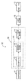
以下、図面を参照しながら本発明の画像処理装置の一実施形態を利用した文字画像読取出力装置について説明する。図1は本文字画像読取出力装置の概略を示すブロック図である。
【0021】
本文字画像読取出力装置10は、文字が記録された原稿を読み取ることにより文字画像データを得る画像読取部11、該画像読取部11により読み取られた文字画像データにおける所定の注目画素がエッジ強調処理を施す対象画素であるか否かを判別し、対象画素と判別された注目画素にエッジ強調処理を施す画像処理装置30、画像処理装置30により対象画素にエッジ強調処理が施された文字画像データに二値化処理を施す二値化処理部15、該二値化処理部15により二値化処理の施された二値化文字画像データに基づいて文字画像を所定の記録媒体に出力する画像出力部16を備えている。
【0022】
画像処理装置30は、画像読取部11により読み取られた文字画像データにおける所定の注目画素が対象画素であるか否かを判別する対象画素判別手段20と、対象画素判別手段20により対象画素と判別された注目画素にエッジ強調処理を施すエッジ強調処理部14とを備えている。
【0023】
また、対象画素判別手段20は、画像読取部11により読み取られた文字画像データにおける所定の注目画素の濃度が、原稿の輪郭部分の下地の濃度よりも高く文字を構成する線のうち最も細い線の濃度以下の所定の第1の閾値以上、かつ文字を構成する線のうち最も細い線の濃度以上の所定の第2の閾値以下である場合にその注目画素を濃度対象画素と判別する濃度判別部12と、濃度判別部12により濃度対象画素であると判別された注目画素が細線画像の一部に応じた細線画素であるか否かを判別する細線画像判別部13とを備えている。
【0024】
次に、本文字画像読取出力装置の作用について説明する。
【0025】
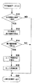
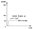
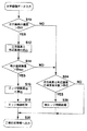
まず、画像読取部11において文字が記録された原稿が光電的に読み取られ、その読み取られた文字画像データが本発明の画像処理装置30に入力される。画像処理装置30に入力された文字画像データについては、図2のフローチャートに示すように、まず、濃度判別部12において、所定の画素に注目し、その注目画素の濃度が予め設定された第1の閾値th1より大きいか否かが判別される(S10)。ここで、上記第1の閾値th1は文字画像が記録された原稿の輪郭部分の下地の濃度よりも高い値である。たとえば、小ポイント文字の読取濃度が図3に示すようになっている場合には、第1の閾値th1は90位に設定される。なお、図3は所定の小ポイント文字の一部を画像読取部11により主走査方向に読み取ったときに出力される画素データの濃度を8ビットのデータとして表した場合の模式図である(白色部分の読取濃度は0、黒色部分の読取濃度は255として表される)。また、上記第1の閾値th1は上述したように原稿の輪郭部分の下地の濃度よりも高い値に設定すればよいが、本実施形態のように小ポイント文字部における文字部の濃度と小ポイント文字部における下地部の濃度との間に設定すれば、上記文字部のみにエッジ強調処理を施すことができるので、効率よくエッジ強調処理を施すことができる。
【0026】
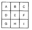
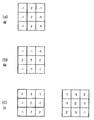
そして、注目画素の濃度が第1の閾値th1以下である場合には、その注目画素の画素データはそのまま二値化処理部15に出力される。一方、S10において注目画素の濃度が第1の閾値th1よりも大きい場合には、その注目画素は濃度対象画素と判別され(本実施形態では、上記特許請求の範囲における第2の閾値は文字を構成する線の最大濃度の値としている)、その濃度対象画素とその濃度対象画素に隣接する周辺画素の画素データが細線画像判別部13に出力される。周辺画素とは、たとえば、図4において画素Eを濃度対象画素とした場合、画素A,B,C,D,F,G,H,Iが周辺画素である。そして、細線画像判別部13においては、濃度対象画素とその周辺画素について、たとえば、図5(a),(b),(c)に示すような縦、横、斜めの細線検出フィルタを用い、極細線量が算出される。極細線量とは、濃度対象画素とその周辺画素の画素データに、フィルタにおける対応画素の係数を掛け合わせて加算した値であり、たとえば、図5(a)の縦線フィルタについての極細線量は、以下のようにして算出される。
【0027】
極細線量:2×(b+e+h)−(a+d+g+c+f+i)
ただし、a〜iはそれぞれ画素A〜Iの画素データ
上記のようにして各フィルタについて極細線量が算出され、その中で最大の極細線量を求め、その最大極細線量と予め設定された細線画像判別用の閾値thlineとを比較する(S14)。そして、最大極細線量が細線画像判別用の閾値thlineより大きい場合には、上記濃度対象画素が細線画像の一部を構成する細線画素であると判別する。そして、上記のようにして濃度対象画素であり、かつ細線画素と判別された場合には、その注目画素は対象画素と判別され、その対象画素の画素データと最大極細線量がエッジ強調処理部14に出力される。エッジ強調処理部14においては、対象画素にエッジ強調処理を施すため、エッジ強調度αを算出する(S16)。エッジ強調度αは、本文字画像読出力装置により出力される文字のうち最も小さいポイントの文字を鮮明に出力することができる程度の大きさであり、所定の固定値としてもよいが、本実施形態では、最大極細線量の大きさに比例させた大きさのエッジ強調度αを算出する。そして、上記のようにして算出されたエッジ強調度αを用いて対象画素にエッジ強調処理が施される。エッジ強調処理は、下式(1)に示すような一般的なラプラシアンなどの高域強調フィルタを使用すればよい。
【0028】
g(i,j)=f(i,j)−α・∇2f(i,j) … (1)
ただし、f(i,j):エッジ強調処理前の画素データ
g(i,j):エッジ強調処理済みの画素データ
上記のようにしてエッジ強調度が施された対象画素の画素データは二値化処理部15に出力される(S20)。一方、S14において、最大極細線量の大きさが細線画像判別用の閾値thline以下である場合には、その注目画素は対象画素ではないと判別し、その画素データはそのまま二値化処理部15に出力される。
【0029】
画像読取部11から出力された文字画像データにおける全ての画素について、それぞれ注目画素として上記と同様の処理が施される。そして、二値化処理部15においては、全ての画素データについて二値化処理が施される。そして、二値化処理部15において処理の施された二値化画素データは、画像出力部16に出力され、二値化画素データに基づいて所定の記録媒体に文字画像が出力される。
【0030】
上記文字画像読取出力装置によれば、濃度判別部12において濃度対象画素と判別されるとともに、細線画像判別部13において細線画素と判別された注目画素を対象画素と判別し、該対象画素にエッジ強調処理を施すようにしたので、エッジ強調処理を施す小ポイント文字を含む文字画像情報について、原稿の輪郭が出力されることなく、かつ鮮明な小ポイント文字を出力することができるようなエッジ強調処理を施すことができる。
【0031】
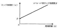
また、上記実施形態においては、S10において注目画素の濃度が第1の閾値th1以下の場合、およびS14において注目画素について最大極細線量が細線画像判別用の閾値thline以下の場合には、その注目画素の画素データはそのまま二値化処理部15に出力するようにしたが、図6のフローチャートに示すように、上記のような場合には、S18において施されるエッジ強調処理よりも弱い強調度の弱エッジ強調処理を注目画素に施すようにしてもよい(S26)。S18において施されるエッジ強調度αとS26において施される弱エッジ強調度βは、所定の固定の値でもよいが、図7に示すような関係で決定するようにすれば通常のエッジ強調処理が施された部分と弱エッジ強調処理が施された部分の境界において不自然さが生じるのを防ぐことができる。図7の直線式の傾きは画像読取部11のMTFを参考に画像チューニングで求めるようにすればよい。また、図7に示すような直線(1次関数)ではなく曲線(2次関数)で表される関係としてもよい。
【0032】
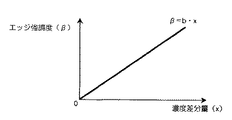
また、S10において注目画素の濃度が第1の閾値th1以下の場合、およびS14において注目画素について最大極細線量が細線画像判別用の閾値thline以下の場合には、注目画素とその周辺画素の濃度差分量を算出する濃度差分量算出手段(不図示)を設け、図8のフローチャートに示すように、その濃度差分量が所定の第3の閾値th3よりも大きい場合には(S24)、注目画素に弱い強調度の弱エッジ強調処理を施し(S26)、濃度差分量が所定の第3の閾値th3以下である場合には(S24)、弱いエッジ強調処理を施さずに注目画素の画素データをそのまま二値化処理部15に出力するようにしてもよい。弱エッジ強調処理の強調度βは、所定の固定の値でもよいが、図9に示すように上記濃度差分量の大きさに比例させた大きさで算出するようにしてもよい。また、S24において濃度差分量が所定の第3の閾値th3以下である場合には、上記のように弱エッジ強調処理を施さないのではなく、上記弱エッジ強調処理よりもさらに弱い強調度のエッジ強調処理を施すようにしてもよい。なお、上記濃度差分量とは、たとえば、注目画素とその周辺画素の濃度差分量のうち最大のものとすればよい。
【0033】
また、上記実施形態では、注目画素が濃度対象画素と判別され、かつ細線画素と判別された場合に、該注目画素を対象画素と判別するようにしたが、最大極細線量と細線画像判別用の閾値thlineとの比較を行なうことなく注目画素の濃度と第1の閾値th1との比較のみを行ない、注目画素の濃度が濃度対象画素と判別された場合には、その濃度対象画素を対象画素とし、その対象画素にエッジ強調処理を施すようにしてもよい。
【図面の簡単な説明】
【図1】本発明の画像処理装置の一実施形態を適用した文字画像読取出力装置の概略ブロック図
【図2】図1に示す文字画像読取出力装置におけるエッジ強調処理を施す作用を示すフローチャート
【図3】小ポイント文字の読取濃度の例を示す図
【図4】周辺画素を説明する図
【図5】細線検出フィルタを示す図
【図6】図1に示す文字画像読取出力装置におけるその他のエッジ強調処理を施す作用を示すフローチャート
【図7】図6のフローチャートにおけるエッジ強調処理の強調度を説明する図
【図8】図1に示す文字画像読取出力装置におけるその他のエッジ強調処理を施す作用を示すフローチャート
【図9】図8のフローチャートにおけるエッジ強調処理の強調度を説明する図
【図10】大ポイント文字の濃度差と小ポイント文字の濃度差を示す図
【符号の説明】
10 文字画像読取出力装置
11 画像読取部
12 濃度判別部
13 細線画像判別部
14 エッジ強調処理部
15 二値化処理部
16 画像出力部
20 エッジ画素判別手段
30 画像処理装置[0001]
TECHNICAL FIELD OF THE INVENTION
The present invention determines whether or not a predetermined pixel of interest in character image information obtained by reading a document on which characters are recorded is a target pixel on which edge enhancement processing is to be performed. The present invention relates to an image processing device that performs processing.
[0002]
[Prior art]
Conventionally, a document on which characters are recorded is read by a scanner or the like to obtain character image information, and it is determined whether a predetermined pixel of interest in the character image information is a target pixel on which edge enhancement processing is performed, An image processing technique for performing edge enhancement processing on the target pixel has been proposed. In particular, when an edge pixel corresponding to the outline of a character is set as the target pixel and an edge enhancement process is performed on the edge pixel, the character image is output to a predetermined recording medium based on the character image information. Various techniques have been proposed that can more clearly output.
[0003]
When performing edge enhancement processing on an edge pixel as described above, first, it is necessary to determine the edge pixel. However,
[0004]
[Patent Document 1]
JP-A-10-240929
[Patent Document 2]
Japanese Patent Publication No. 3115065
[Problems to be solved by the invention]
However, the pixel density in the character image information when a large point character is read and the pixel density in the character image information when a small point character is read have a relationship as shown in FIG. The density difference of the pixels in the character image information is smaller than the density difference of the pixels in the character image information corresponding to the large point character. This schematically shows the density of the pixel data output when the image is read, with the peaks indicating the density of the character portion and the valleys indicating the density of the base portion in the character portion. Therefore, in the method described in
[0007]
Further, in
[0008]
In addition, it is possible to perform edge emphasis processing on the edge pixels with a degree of emphasis such that the outline of the document is not output. However, it becomes difficult to output small point characters clearly.
[0009]
The present invention has been made in view of the above circumstances, and enables character point information including the small point character as described above to be able to output the small point character clearly without outputting the outline of the document. It is an object of the present invention to provide an image processing apparatus capable of performing edge enhancement processing on the character image information.
[0010]
[Means for Solving the Problems]
The image processing apparatus according to the present invention is configured to determine whether or not a predetermined target pixel in character image information obtained by reading a document on which characters are recorded is a target pixel on which edge enhancement processing is to be performed. An image processing apparatus for performing edge enhancement processing on a pixel of interest determined as a target pixel by the target pixel determination unit, wherein the edge pixel determination unit determines that the density of the pixel of interest is the density of the background of the contour portion of the document. Higher than a predetermined first threshold equal to or lower than the density of the thinnest line among the lines constituting the character and lower than a predetermined second threshold equal to or higher than the density of the thinnest line among the lines forming the character A density determining unit that determines the target pixel as a density target pixel; and a fine line image determining unit that determines whether the target pixel is a fine line pixel that forms part of the fine line image. Picture While being judged, and characterized in that to determine the target pixel to the target pixel is determined that thin line pixel in fine line image discrimination unit.
[0011]
Here, the “predetermined pixel of interest” means a pixel arbitrarily focused on in the character image information.
[0012]
The “edge enhancement processing” includes, for example, an edge enhancement processing using Laplacian, but is not limited thereto, and various edge enhancement processings can be used.
[0013]
The "second threshold value" may be any value as long as it is equal to or higher than the density of the thinnest line of the characters. For example, the "second threshold value" may be set to the maximum density value of the line configuring the characters. When the density is equal to or more than the “first threshold”, the target pixel may be set as a density target pixel.
[0014]
The “fine line image” means, for example, an image extending in a predetermined direction with a width of one or several pixels in the character image information. It can be arbitrarily determined according to the situation.
[0015]
In the image processing apparatus, a target pixel that is not determined as a target pixel by the target pixel determining unit is set as a non-target pixel, and the non-target pixel is subjected to a weak edge enhancement process with a lower degree of enhancement than the edge enhancement process. Can be
[0016]
In the image processing apparatus, the target pixel that is not determined as the target pixel by the target pixel determining unit is set as a non-target pixel, and a density difference amount between the non-target pixel and a peripheral pixel adjacent to the non-target pixel is calculated. A density difference amount calculating means for calculating the density difference amount calculated by the density difference amount calculating means. When the weak edge enhancement processing is performed and the density difference amount is smaller than a predetermined threshold value, the non-target pixel can be configured not to perform the weak edge enhancement processing.
[0017]
【The invention's effect】
According to the image processing apparatus of the present invention, the density discrimination section discriminates the pixel of interest from the target pixel determined as the fine line pixel by the fine line image determination section while performing edge enhancement processing. Therefore, with respect to the character image information including the small point characters to be subjected to the edge enhancement processing, the edge enhancement processing can be performed so that the outline of the document is not output and the small point characters can be output clearly. . Further, since it is determined whether or not the pixel is a thin line pixel, for example, the first pixel which is set in advance by a slight change in the density of the background of the outline of the document despite being the target pixel in the outline of the document. The target pixel that is equal to or larger than the threshold value and has been determined to be a density target pixel can also be excluded by the fine line image determination unit so that the edge enhancement processing is not performed. Further, since the edge enhancement processing is performed only on the thin line pixels, it is possible to avoid performing unnecessary edge enhancement processing on portions other than the thin line image.
[0018]
Further, in the above image processing apparatus, when a non-target pixel that is not determined as a target pixel by the target pixel determining unit is subjected to a weak edge enhancement process with a weaker degree of enhancement than the edge enhancement process, for example, a character image Even if the lens used to obtain the information could only obtain low-cost, low-sharpness character image information, it was recorded on the manuscript by applying weak edge enhancement processing to pixels other than the target pixel. The whole image can be output clearly.
[0019]
Further, in the image processing apparatus, when the density difference between the non-target pixel not determined as the target pixel by the target pixel determining unit and a peripheral pixel adjacent to the non-target pixel is equal to or larger than a predetermined threshold value, If the target pixel is subjected to a weak edge enhancement process with a degree of enhancement lower than the edge enhancement process, and if the density difference amount is smaller than a predetermined threshold, the non-target pixel is not subjected to the weak edge enhancement process. Can clearly output the entire image recorded on the document in the same manner as described above.
[0020]
BEST MODE FOR CARRYING OUT THE INVENTION
Hereinafter, a character image reading and outputting apparatus using an embodiment of the image processing apparatus of the present invention will be described with reference to the drawings. FIG. 1 is a block diagram schematically showing the character image reading and outputting apparatus.
[0021]
The character image reading
[0022]
The
[0023]
The target
[0024]
Next, the operation of the character image reading and outputting apparatus will be described.
[0025]
First, an original on which characters are recorded is photoelectrically read by the image reading unit 11, and the read character image data is input to the
[0026]
When the density of the target pixel is equal to or less than the first threshold th1, the pixel data of the target pixel is output to the
[0027]
Extra fine dose: 2 × (b + e + h) − (a + d + g + c + f + i)
Here, a to i are the pixel data of the pixels A to I, respectively. The extra fine dose is calculated for each filter as described above, the maximum extra fine dose is obtained, and the maximum extra fine dose is determined as a predetermined fine line image discrimination. Is compared with the threshold th line (S14). If the maximum extra fine dose is larger than the threshold value th line for discriminating a thin line image, it is determined that the density target pixel is a thin line pixel constituting a part of the thin line image. When the pixel of interest is determined to be a density target pixel and a thin line pixel as described above, the target pixel is determined to be a target pixel, and the pixel data of the target pixel and the maximum extra fine dose are applied to the edge
[0028]
g (i, j) = f (i, j) −α · ∇ 2 f (i, j) (1)
Here, f (i, j): pixel data before edge enhancement processing g (i, j): pixel data after edge enhancement processing The pixel data of the target pixel subjected to the edge enhancement degree as described above is binary. It is output to the conversion processing unit 15 (S20). On the other hand, when the magnitude of the maximum extra fine dose is equal to or smaller than the thin line image discrimination threshold th line in S14, it is determined that the target pixel is not the target pixel, and the pixel data is directly used as the
[0029]
The same processing as described above is performed on all the pixels in the character image data output from the image reading unit 11 as the pixels of interest. Then, the
[0030]
According to the character image reading and outputting apparatus, the
[0031]
In the above embodiment, the density of the target pixel in S10 if less than or equal to a first threshold th1, and when the maximum-fine dose for the pixel of interest is equal to or less than the threshold th line of thin wire for image discrimination step S14, the target Although the pixel data of the pixel is output to the
[0032]
If the density of the target pixel is equal to or less than the first threshold th1 in S10, and if the maximum extra fine dose of the target pixel is equal to or smaller than the threshold th line for thin line image determination in S14, the density of the target pixel and its surrounding pixels A density difference amount calculating means (not shown) for calculating the difference amount is provided. As shown in the flowchart of FIG. 8, when the density difference amount is larger than a third threshold value th3 (S24), the target pixel is set. Is subjected to a weak edge enhancement process with a low degree of weakness (S26), and if the density difference amount is equal to or smaller than a third threshold th3 (S24), the pixel data of the target pixel is not subjected to the weak edge enhancement process. You may make it output to the
[0033]
Further, in the above embodiment, when the target pixel is determined as the density target pixel and is determined as the fine line pixel, the target pixel is determined as the target pixel. Only the density of the target pixel is compared with the first threshold th1 without comparing with the threshold th line, and when the density of the target pixel is determined to be the density target pixel, the density target pixel is set as the target pixel. The edge enhancement processing may be performed on the target pixel.
[Brief description of the drawings]
FIG. 1 is a schematic block diagram of a character image reading and outputting apparatus to which an embodiment of the image processing apparatus of the present invention is applied. FIG. 2 is a flowchart showing an operation of performing an edge enhancement process in the character image reading and outputting apparatus shown in FIG. FIG. 3 is a diagram showing an example of the reading density of a small point character. FIG. 4 is a diagram illustrating peripheral pixels. FIG. 5 is a diagram showing a fine line detection filter. FIG. 6 is another diagram in the character image reading and outputting apparatus shown in FIG. FIG. 7 is a flowchart illustrating an operation of performing edge enhancement processing. FIG. 7 is a diagram illustrating an enhancement degree of the edge enhancement processing in the flowchart of FIG. 6. FIG. 8 is an operation of performing other edge enhancement processing in the character image reading and outputting apparatus illustrated in FIG. FIG. 9 is a diagram for explaining the degree of emphasis of the edge emphasis processing in the flowchart of FIG. 8; Shows a degree difference [Description of symbols]
REFERENCE SIGNS
Claims (3)
前記エッジ画素判別手段が、
前記注目画素の濃度が前記原稿の輪郭部分の下地の濃度よりも高く前記文字を構成する線のうち最も細い線の濃度以下の所定の第1の閾値以上かつ前記文字を構成する線のうち最も細い線の濃度以上の所定の第2の閾値以下の場合に前記注目画素を濃度対象画素と判別する濃度判別部と、
前記注目画素が細線画像の一部を構成する細線画素であるか否かを判別する細線画像判別部とを有し、
前記濃度判別部において前記濃度対象画素と判別されるとともに、前記細線画像判別部において前記細線画素と判別された前記注目画素を前記対象画素と判別するものであることを特徴とする画像処理装置。A target pixel determining unit that determines whether a predetermined pixel of interest in character image information obtained by reading a document on which characters are recorded is a target pixel to be subjected to edge enhancement processing; In an image processing apparatus that performs edge enhancement processing on a target pixel determined as the target pixel by the determination unit,
The edge pixel determining means,
The density of the pixel of interest is higher than the density of the background of the contour portion of the document, and is equal to or greater than a predetermined first threshold value equal to or less than the density of the thinnest line among the lines constituting the character and the highest among the lines constituting the character. A density determination unit that determines the target pixel as a density target pixel when the density is equal to or less than a predetermined second threshold value equal to or more than the density of a thin line;
A thin line image determining unit that determines whether the pixel of interest is a thin line pixel forming a part of the thin line image,
An image processing apparatus, wherein the density discriminating unit discriminates the target pixel from the target pixel determined as the density target pixel and the thin line image determining unit determines the target pixel determined as the thin line pixel.
該濃度差分量算出手段により算出された濃度差分量が所定の第3の閾値以上である場合には、前記非対象画素に前記エッジ強調処理よりも弱い強調度の弱エッジ強調処理を施し、
前記濃度差分量が所定の第3の閾値よりも小さい場合には、前記非対象画素に前記弱エッジ強調処理を施さないことを特徴とする請求項1記載の画像処理装置。A target pixel which is not determined as the target pixel by the target pixel determining unit is set as a non-target pixel, and a density difference calculating unit calculates a density difference between the non-target pixel and a peripheral pixel adjacent to the non-target pixel. ,
When the density difference amount calculated by the density difference amount calculation means is equal to or more than a predetermined third threshold value, the non-target pixel is subjected to a weak edge enhancement process with a degree of enhancement smaller than the edge enhancement process,
The image processing apparatus according to claim 1, wherein the weak edge enhancement process is not performed on the non-target pixel when the density difference amount is smaller than a third predetermined threshold value.
Priority Applications (2)
| Application Number | Priority Date | Filing Date | Title |
|---|---|---|---|
| JP2002266317A JP3989341B2 (en) | 2002-09-12 | 2002-09-12 | Image processing device |
| US10/660,683 US7463785B2 (en) | 2002-09-12 | 2003-09-12 | Image processing system |
Applications Claiming Priority (1)
| Application Number | Priority Date | Filing Date | Title |
|---|---|---|---|
| JP2002266317A JP3989341B2 (en) | 2002-09-12 | 2002-09-12 | Image processing device |
Publications (2)
| Publication Number | Publication Date |
|---|---|
| JP2004104635A true JP2004104635A (en) | 2004-04-02 |
| JP3989341B2 JP3989341B2 (en) | 2007-10-10 |
Family
ID=31986635
Family Applications (1)
| Application Number | Title | Priority Date | Filing Date |
|---|---|---|---|
| JP2002266317A Expired - Fee Related JP3989341B2 (en) | 2002-09-12 | 2002-09-12 | Image processing device |
Country Status (2)
| Country | Link |
|---|---|
| US (1) | US7463785B2 (en) |
| JP (1) | JP3989341B2 (en) |
Cited By (1)
| Publication number | Priority date | Publication date | Assignee | Title |
|---|---|---|---|---|
| JP2009065322A (en) * | 2007-09-05 | 2009-03-26 | Nec Access Technica Ltd | Image output device and method |
Families Citing this family (8)
| Publication number | Priority date | Publication date | Assignee | Title |
|---|---|---|---|---|
| TW200729082A (en) * | 2006-01-27 | 2007-08-01 | Marketech Int Corp | Apparatus and method for adjusting sharpness of image |
| TWI323606B (en) * | 2006-02-22 | 2010-04-11 | Huper Lab Co Ltd | Image noise reduction method based on local correlation |
| JP4181187B2 (en) * | 2006-05-31 | 2008-11-12 | 京セラミタ株式会社 | Image forming apparatus |
| US8224112B2 (en) * | 2009-06-08 | 2012-07-17 | Xerox Corporation | Fuzzy method to detect thin lines in scanned image |
| US8254694B2 (en) * | 2009-06-08 | 2012-08-28 | Xerox Corporation | Thin line detection in scanned image data |
| US7844118B1 (en) * | 2009-07-01 | 2010-11-30 | Xerox Corporation | Image segmentation system and method with improved thin line detection |
| CN104134198A (en) * | 2014-07-28 | 2014-11-05 | 厦门美图之家科技有限公司 | Method for carrying out local processing on image |
| CN111461019B (en) * | 2020-04-01 | 2023-04-07 | 黑龙江文茁教育科技有限公司 | Method, system and equipment for evaluating Chinese character writing quality |
Family Cites Families (13)
| Publication number | Priority date | Publication date | Assignee | Title |
|---|---|---|---|---|
| EP0385009A1 (en) * | 1989-03-03 | 1990-09-05 | Hewlett-Packard Limited | Apparatus and method for use in image processing |
| JP3115065B2 (en) * | 1991-11-11 | 2000-12-04 | 株式会社リコー | Image information edge enhancement device |
| US5751854A (en) * | 1992-08-03 | 1998-05-12 | Ricoh Company, Ltd. | Original-discrimination system for discriminating special document, and image forming apparatus, image processing apparatus and duplicator using the original-discrimination system |
| KR950012731A (en) * | 1993-10-25 | 1995-05-16 | 사토 후미오 | Semiconductor memory device and manufacturing method |
| EP0685961B1 (en) * | 1994-06-03 | 2000-08-23 | Riso Kagaku Corporation | Image processing apparatus |
| JP3427554B2 (en) * | 1995-03-01 | 2003-07-22 | オムロン株式会社 | Image processing apparatus and method |
| JPH08255240A (en) * | 1995-03-17 | 1996-10-01 | Dainippon Screen Mfg Co Ltd | Device and method for correcting image |
| JPH10240929A (en) | 1997-02-28 | 1998-09-11 | Casio Comput Co Ltd | Image processing device |
| JPH11150659A (en) * | 1997-11-18 | 1999-06-02 | Matsushita Electric Ind Co Ltd | Image processing method |
| JP2000030050A (en) * | 1998-07-14 | 2000-01-28 | Minolta Co Ltd | Picture processor, its method, and recording medium having recorded picture processing program thereon |
| US6175659B1 (en) * | 1998-10-06 | 2001-01-16 | Silicon Intergrated Systems Corp. | Method and apparatus for image scaling using adaptive edge enhancement |
| US6750986B1 (en) * | 2000-03-27 | 2004-06-15 | Destiny Technology Corporation | Color image processing method with thin-line detection and enhancement |
| US6917446B2 (en) * | 2000-09-21 | 2005-07-12 | Kyocera Mita Corporation | Image processing apparatus and image processing method |
-
2002
- 2002-09-12 JP JP2002266317A patent/JP3989341B2/en not_active Expired - Fee Related
-
2003
- 2003-09-12 US US10/660,683 patent/US7463785B2/en not_active Expired - Lifetime
Cited By (1)
| Publication number | Priority date | Publication date | Assignee | Title |
|---|---|---|---|---|
| JP2009065322A (en) * | 2007-09-05 | 2009-03-26 | Nec Access Technica Ltd | Image output device and method |
Also Published As
| Publication number | Publication date |
|---|---|
| US20040052428A1 (en) | 2004-03-18 |
| JP3989341B2 (en) | 2007-10-10 |
| US7463785B2 (en) | 2008-12-09 |
Similar Documents
| Publication | Publication Date | Title |
|---|---|---|
| JP2871127B2 (en) | Image processing apparatus and method | |
| JPH0766977A (en) | Picture processing unit | |
| JPH05227425A (en) | Improvement in automatic image segmentation | |
| JP3576810B2 (en) | Image processing device | |
| JP3989341B2 (en) | Image processing device | |
| JP3568732B2 (en) | Image processing device | |
| JP4502001B2 (en) | Image processing apparatus and image processing method | |
| JPH0879517A (en) | Method for identifying type of image | |
| JPH0950519A (en) | Image processing apparatus and method | |
| JPH09212642A (en) | Image processing device | |
| JP4324532B2 (en) | Image processing apparatus and storage medium | |
| JP3705414B2 (en) | Binarization threshold determination method | |
| JPS6180964A (en) | Picture signal processing method | |
| JPH0457274B2 (en) | ||
| JP3605773B2 (en) | Image area discriminating device | |
| JPH05344330A (en) | Picture area discriminating device | |
| JP3705405B2 (en) | Binarization threshold determination method | |
| JP2937603B2 (en) | Binary discrimination method of image data in image data reading device | |
| JP3036244B2 (en) | Image signal processing device | |
| JPH02186876A (en) | Image processing device | |
| JP2507927B2 (en) | Image processing device | |
| JPH03219774A (en) | Image processing method and device | |
| JP2001197306A (en) | White background area detection method, white background area detection device, image area separation method, and recording medium | |
| JPS6356064A (en) | Picture processing method | |
| JP3748366B2 (en) | Binarization and binarization threshold determination method |
Legal Events
| Date | Code | Title | Description |
|---|---|---|---|
| A621 | Written request for application examination |
Free format text: JAPANESE INTERMEDIATE CODE: A621 Effective date: 20050617 |
|
| A977 | Report on retrieval |
Free format text: JAPANESE INTERMEDIATE CODE: A971007 Effective date: 20070614 |
|
| TRDD | Decision of grant or rejection written | ||
| A01 | Written decision to grant a patent or to grant a registration (utility model) |
Free format text: JAPANESE INTERMEDIATE CODE: A01 Effective date: 20070625 |
|
| A61 | First payment of annual fees (during grant procedure) |
Free format text: JAPANESE INTERMEDIATE CODE: A61 Effective date: 20070717 |
|
| FPAY | Renewal fee payment (event date is renewal date of database) |
Free format text: PAYMENT UNTIL: 20100727 Year of fee payment: 3 |
|
| R150 | Certificate of patent or registration of utility model |
Free format text: JAPANESE INTERMEDIATE CODE: R150 Ref document number: 3989341 Country of ref document: JP Free format text: JAPANESE INTERMEDIATE CODE: R150 |
|
| FPAY | Renewal fee payment (event date is renewal date of database) |
Free format text: PAYMENT UNTIL: 20110727 Year of fee payment: 4 |
|
| R250 | Receipt of annual fees |
Free format text: JAPANESE INTERMEDIATE CODE: R250 |
|
| FPAY | Renewal fee payment (event date is renewal date of database) |
Free format text: PAYMENT UNTIL: 20110727 Year of fee payment: 4 |
|
| FPAY | Renewal fee payment (event date is renewal date of database) |
Free format text: PAYMENT UNTIL: 20120727 Year of fee payment: 5 |
|
| R250 | Receipt of annual fees |
Free format text: JAPANESE INTERMEDIATE CODE: R250 |
|
| FPAY | Renewal fee payment (event date is renewal date of database) |
Free format text: PAYMENT UNTIL: 20120727 Year of fee payment: 5 |
|
| FPAY | Renewal fee payment (event date is renewal date of database) |
Free format text: PAYMENT UNTIL: 20130727 Year of fee payment: 6 |
|
| R250 | Receipt of annual fees |
Free format text: JAPANESE INTERMEDIATE CODE: R250 |
|
| R250 | Receipt of annual fees |
Free format text: JAPANESE INTERMEDIATE CODE: R250 |
|
| R250 | Receipt of annual fees |
Free format text: JAPANESE INTERMEDIATE CODE: R250 |
|
| R250 | Receipt of annual fees |
Free format text: JAPANESE INTERMEDIATE CODE: R250 |
|
| R250 | Receipt of annual fees |
Free format text: JAPANESE INTERMEDIATE CODE: R250 |
|
| R250 | Receipt of annual fees |
Free format text: JAPANESE INTERMEDIATE CODE: R250 |
|
| R250 | Receipt of annual fees |
Free format text: JAPANESE INTERMEDIATE CODE: R250 |
|
| R250 | Receipt of annual fees |
Free format text: JAPANESE INTERMEDIATE CODE: R250 |
|
| R250 | Receipt of annual fees |
Free format text: JAPANESE INTERMEDIATE CODE: R250 |
|
| R250 | Receipt of annual fees |
Free format text: JAPANESE INTERMEDIATE CODE: R250 |
|
| LAPS | Cancellation because of no payment of annual fees |