【0001】
【発明の属する技術分野】
本発明は、汚染物質の除去が必要な物品の清浄化、特に電子デバイス用基板の清浄化方法に関するものである。具体的には本発明は、半導体用ウェーハ又は液晶用基板などの加工に際して使用するフォトレジストのような有機膜の除去並びにウェ−ハ工程全般に亙って発生する有機汚染の洗浄に関するものである。さらに広く、本発明は精密な金属加工品やガラス加工品の有機汚染の洗浄に関するものである。
【0002】
【従来の技術】
酸化膜やポリシリコン膜上の微細加工に使用したフォトレジストの除去に関しては、通常硫酸(3容又は4容):過酸化水素(1容)の混合液(ピラニアと呼ばれている)で110〜140℃に加熱して10〜20分浸漬する方法が使われている。レジストマスクで高濃度のイオン注入を行うような場合にはレジストが変質してピラニア処理では除去できなくなるので、プラズマ励起酸素によるアッシングが広く使われている。しかし全部のフォトレジストをアッシングすると、ウェーハ表面にレジスト由来の微量金属が残り、かつ高エネルギーのプラズマの為にウェーハ表面にデバイスにとって有害な損傷を生じる。そこでレジスト膜を残してアッシングし、その後はピラニア処理でレジストを除去することが行われている。このピラニア処理の過酸化水素の代りにオゾンを混合することも試みられたが、オゾンの低い溶解度の為、除去にはさらに長時間の処理を要し、殆ど使われていない。
【0003】
最近オゾン水によるレジスト除去法が登場した。オゾンは低温ほど水への溶解度が増し、約5℃の超純水ではオゾンの溶解量は70〜100ppmに達する。このような低温高濃度のオゾン水でレジストを除去すると、LSI製造で広く使われているI線用ポジ型ノボラック樹脂系フォトレジスト膜の場合、800nmの厚さを10乃至15分程度で剥離出来る(剥離速度70〜80nm/分)といわれている。
半導体デバイス製造用のクリーンルーム内の雰囲気からはフタル酸ジオクチル(DOP)、シロキサン類、ヘキサメチルジシラザン(HMDS)等の有機物がシリコンウェーハや酸化膜等の表面を汚染し、これがデバイス特性を劣化させ、デバイスの歩留が低下することが知られている。
【0004】
シリコンウェーハや酸化膜上の有機物を除去する湿式洗浄法としては、上記のピラニア処理が最も有効とされてきた。しかし、SO4 2−はウェーハ上に残って環境雰囲気の影響で微粒子を生じ、ヘイズを起こしやすい。これを完全に除く為、通常はSC−1処理(標準的組成はNH4 OH:H2 O2 :H2 O=1容:1容:5容)等を後続させている。SC−1処理は単独でも有機物を分解除去する作用があり、また微粒子を除去する作用では従来最も効果が大きいとされてきた。しかし、SC−1では薬液中のFe,Al,Ca,Mg,Zn,Ni等は洗浄中にウェーハに沈着しやすく、薬液や洗浄槽の清浄度管理が難しい。そこで稀HFでSC−1処理で生じたケミカル酸化膜を除き、金属除去能力が優れると考えられているSC−2処理(標準的組成はHCl:H2 O2 :H2 O=1容:1容:6容)を行うのが半導体洗浄の常套手段となって、RCA法と呼ばれている。表面残存SO4 2−を除く為には、長時間大量の加熱水リンスを行うような手法も使われているが、達成できる清浄度が通常RCA法を後続させた場合には劣る。
【0005】
有機汚染したウェーハに対する洗浄法として、従来から行われてきたピラニア処理に依存する処理は経済性・生産性・安全性の面で満足なものとは言えない。これらを解決する新しい洗浄法としてオゾン水によるものが登場してきた。オゾン水は室温では20〜30ppmのものが得られるので、この酸化力によってウェーハの有機汚染を除こうとするものである。
【0006】
【発明が解決しようとする課題】
半導体デバイス特に超LSIの高度化と共にウェーハ表面の有機汚染の低減はますます重要性を高めている。米国半導体工業会が発表するロードマップでは、最近まで表面有機炭素濃度に関する記載はなかった。1997年末に発表されたでものでは1×10¹⁴原子/cm2の有機炭素濃度を許容しているが、2009年にはこの濃度は1.8×1013原子/cm2が必要としている。レジスト剥離後も勿論この清浄度が必要である。ピラニア洗浄液は経済性の点で繰り返し使われるが、ポジ型レジスト用密着剤HMDSで生じる酸化膜上のメチルシリコン層をこのような高い清浄度レベルまで除去しようとすると、繰り返し使用で劣化したピラニア洗浄液では難しくなるので、使用回数を厳しく制限しなければならなくなる。従って、硫酸の使用量が増すことになり、経済性が悪くなるだけでなく廃水処理の面でも厄介になる。
また、金属膜上のレジストの除去は強い酸の処理では該膜を損なうので、N−メチルピロリドン(NMP)を除去剤とし、約70℃で15分程度の溶解処理がなされている。この場合はイソプロピルアルコールのような有機溶剤のリンスを経て超純水リンスを行なっている。この処理は有機溶剤の使用量が多く、経済性の点で望ましくない他、廃水処理でも費用がかかる。
【0007】
従って、オゾン水処理が期待されるわけであるが、半導体レベルの高純度オゾン水はオゾンを含む高純度ガスを超純水に吸収させて製造している。ところで、液体を入れた容器にオゾンを含むガスを注入した場合に、ガス中のオゾン濃度をCG [mg/L]、飽和状態になった液中のオゾンの濃度をCL [mg/L]とすると、分配係数D=CL /CG となる。ここで、液が水の場合、ある研究例では25℃でD=0.2、20℃でD=0.28、5℃でD=0.47の値となっており、通常の高純度オゾンガス発生装置で得られるオゾン濃度は200mg/L程度であるから、これで計算すると25℃で40ppm、5℃で94ppmが飽和濃度となる。実用上は上記のようにこの濃度よりやや低い濃度しか得られない。しかもオゾンは水中で分解しやすく、オゾン水洗浄槽中のオゾン濃度はオゾン水を循環して常にオゾンガスを注入しないと最高水準を維持出来ない。また、洗浄槽内ではウェーハキャリアのような流れに対して障害となるものがあると、ウェーハ表面にオゾンが不足する部分が出来て、レジスト剥離速度が減少する。レジスト自体の剥離速度は100nm/分程度の値があったとしても、ウェーハキャリア内の全部のウェーハについてメチルシリコンの層まで完全に除去するには、この剥離速度から計算される処理時間の2倍以上を必要とする。即ち、厚さ1μmのレジスト膜の除去に20〜30分を要する。
【0008】
本発明は、このようなレジスト密着剤の完全な除去を含めた浸式レジスト剥離を短時間化し、かつ処理後の表面の炭素量が1012原子/cm2のオーダまで低減出来、フォトレジスト除去方法としても有効である清浄化処理法を提供するものである。
【0009】
半導体用のクリーンルーム内においてウェーハ上に最も多い量で検出される有機物は通常DOPで、その量は6″ウェーハ表面で200ngを越すことも多い。このDOPはウェーハ面では微細な斑点状油膜を形成しており、ここに付着した汚染微粒子はこの油膜の液架橋によって強く表面に捕捉され、洗浄による除去が難しくなる。この現象はウェーハ裏側の表面で著しく表側の面より桁違いの量となることがある。なぜならば、デバイス製造工程ではウェーハの裏面を真空チャックのように他の材料に接して処理する場合があり、この材料面が通常親油性なのでDOP等で汚染してこれが転写されるからである。半導体デバイス製造工程ではウェーハの裏側の面が隣接ウェーハの表側の面と対面して、同時に多数枚が処理される場合があり、この時裏側の有機物汚染や微粒子汚染の影響が対面するデバイス形成表面に及ぶ。DOP等による汚染があると、洗浄工程で金属汚染の除去が妨害されることが知られており、この裏側が起こす悪影響には金属汚染も含まれる。
【0010】
そこで本発明はまた、ウェーハの表側と裏側の表面の汚染汚染物質が強力に除去出来、かつ汚染金属の除去も可能な基板面の清浄化処理法を提供するものである。また、この有機汚染除去は極めて強力でありかつ環境に対する公害も管理が容易な為、電子デバイス用基板以外の洗浄体にも適用可能な清浄化法を提供するものである。
【0011】
【課題を解決するための手段】
この目的を達成するために、本発明は、汚染物質の付着した被処理体の表面に、気体中のオゾンとの分配係数が0.6以上である有機溶剤にオゾンを100ppm以上溶解させた処理液を接触させて、被処理体表面の付着汚染物質を除去することを特徴とする表面付着汚染物質の除去方法を提供するものである。
【0012】
【発明の実施の形態】
また本発明は、上記方法の好ましい実施形態として、汚染物質の付着した被処理体の表面に、前記処理液の液膜を形成させ、連続或いは間欠的にその液膜に対し新たな該処理液を供給して液膜を移動させることにより、被処理体表面と含オゾン処理液を接触させることを特徴とする表面付着汚染物質の除去方法を提供するものである。
【0013】
これは後述のように酢酸のような特定の有機溶剤が水の場合より約10倍もオゾンを溶解し、液膜でもその中のオゾンが表面付着汚染物質に作用するのに十分な量であることによる。液膜に接する雰囲気中のオゾン濃度が液中のオゾンとの平衡濃度より高ければ、オゾンは容易に液膜中に拡散し短時間に液のオゾン濃度が飽和近くまで上昇する。
【0014】
そこで本発明は、上記方法の別の好ましい実施形態として、オゾンを含む雰囲気中で、汚染物質の付着した被処理体の表面に、前記有機溶剤の液膜を形成させ、連続或いは間欠的にその液膜に対し新たな該溶剤を供給して膜の液を移動させることにより、被処理体表面と含オゾン処理液を接触させることを特徴とする表面付着汚染物質の除去方法を提供するものである。
【0015】
本発明は、上記表面付着汚染物質の除去に際し、除去処理後の含オゾン有機溶剤液をオゾンを溶解させる該有機溶剤に復帰合体させ、被処理体の除去処理液として供給し、該有機溶剤液を循環使用する処理方法と装置を提供するものである。酢酸のような非極性の有機溶剤はオゾンによって分解されることが少く、例えば酢酸は常用有機溶媒中オゾンに対し、最も安定な物質の一つであり、しかもオゾンに対する溶解度が高い。この溶解されたオゾンは不飽和結合をもつ有機物に対して強い反応性をもち、分解作用を有するだけでなく、十分な反応時間があれば最終的にオゾンに対し安定なカルボン酸や炭酸ガス並びに水等に分解してしまう。即ちこの循環プロセスでは、除去処理にとって必要な精製が行われ、除去処理液の寿命を長く出来る。極めて経済性の優れた本発明の最も特徴的な効果のある処理が提供される。
【0016】
この有機溶剤液の供給は該液の噴霧で行われてもよく、この場合の膜の液の移動は流下でも、遠心力によるものでもよい。また、この液供給は加熱された該液から発生する蒸気が冷却被処理体表面上で液化することによって行われてもよく、この場合、その凝縮液の流下による蒸気洗浄機構で付着汚染物質を除去することになる。本発明はまた、このような有機溶剤液の供給による被処理体表面の液膜の移動をオゾンガスが導入されるチャンバー内で行う被処理体表面の付着汚染物質除去装置を提供するものである。
【0017】
本発明において、有機溶剤による被処理体表面の付着汚染物質除去の際、逆に被処理体表面に有機溶剤分子が若干吸着する。しかし、その吸着量は炭素濃度で(1013〜1014)原子/cm2という低いレベルとなる。これは接触させた液に含まれる有機溶剤が有機物ではあっても分子中に炭素原子が少なくかつ共存するオゾンが極めて高濃度であるためである。これは本発明の最大の特色とするところである。かつ、こうして吸着した有機物の被処理体への付着力は弱く、酸化性処理により容易に炭素濃度を1012原子/cm2の低いオーダーまでさらに低下させることができる。酸化性処理としては、例えば、アルカリ・過酸化水素洗浄のような酸化性洗浄や、あるいは184.9nmと253.7nmの紫外線照射下でのオゾンでの酸化処理が挙げられる。また、被処理体表面がシリコン酸化膜からなる場合には、希フッ酸による表面層の僅かな剥離により、これに近い炭素濃度レベルまで吸着分子を除去することができる。
【0018】
本発明に使用する、気体中のオゾンとの分配係数が0.6以上である有機溶剤は、一般に非極性の有機溶剤である。該分配係数(D)は、標準状態において液相の有機溶剤とこれと接する気相状態の不活性ガスとの間におけるオゾンの分配係数である。即ち、
D=有機溶剤中飽和オゾン濃度(mg/L)/ガス中平衡オゾン濃度(mg/L)
で示される。
本発明で使用される有機溶剤の分配係数は、好ましくは1.0以上、より好ましくは1.5以上、さらに好ましくは2.0以上である。
気体中のオゾンとの分配係数が0.6以上である有機溶剤であれば、特に制限なく本発明に使用することができるが、環境、衛生等に対する影響の面から好ましい有機溶剤は、
式:Cn H2n+1(COOH)[n=1,2又は3の整数]で表される脂肪酸及びジクロロメタンであり、特に好ましくは前記脂肪酸である。該脂肪酸には、酢酸、プロピオン酸及び酪酸が含まれる。これらの有機溶剤は一種単独でも二種以上混合しても使用することができる。
【0019】
本発明において、前記処理液中のオゾン濃度は100ppm以上であり、200ppm以上であることがより好ましい。オゾン濃度が100ppm未満では、十分な汚染物質除去作用が得られないことがある。
上記のような脂肪酸の純度99.7%のものは25℃で略D=1.9なので、純水の場合より約10倍高濃度のオゾン液が得られる。従ってオゾン水の場合より遥かに強い汚染物質除去能力を示す。除去処理はこのオゾン液への浸漬でもよいが、これらの有機溶剤の表面張力が非常に小さく、30dyn/cm以下なのを利用してその液膜で処理することが好ましい。液は被処理体表面全体に容易に膜状に広がる。ここで液が移動すると液に作用された表面汚染物質も同時に移動して効率のよい除去が進展する。また付着有機物に掴まっていた微粒子も表面張力の小さい液に有機物が溶けかつその液が移動する為、容易に除去される。
【0020】
これらのカルボン酸の中では価格の面や高純度の市販品が入手しやすいこと、毒性の点で問題が殆ど無いことから、n=1の酢酸が好ましい。融点が16℃で扱いにくい面もあるが、通常のクリーンルーム温度では問題がなく、後述のように回収については有利な面もある。n=2のプロピオン酸は融点が−20℃であるから、酸に侵されやすい被処理体に対し、酸の働きは弱めオゾンは高濃度に出来る低温処理が可能となる。n=3の酪酸は引火点が72℃で酢酸やプロピオン酸より約20℃高い。加温によって反応を促進させたい場合、危険を避けて70℃近い処理が可能となる。
【0021】
酢酸は水を若干含む方が無機塩を溶解しやすく、また凝固温度が下がって使いやすい。純度97%でもD=1.7、95%でもD=1.5、90%でD=1.3、85%でD=1.1で十分高濃度のオゾン液が得られる。従って、酢酸に5容量%以下の無機酸特にフッ酸を含む水を添加すると金属汚染物を同時によく除去出来る。このように高いD値がえられるので、高純度オゾンガス発生装置で得られるオゾンガスを多数の微細孔から純度85%以上の酢酸にバブリングさせると、オゾン濃度が100mg/L程度でも、容易にオゾン濃度は100ppm以上となり、本発明に提供し得る。オゾン濃度200mg/Lのオゾンガスを使用すると液のオゾン濃度は数分間で200ppm以上となる。
オゾンガスをバブリングさせる発散器具として、ガラスフィルターを使うと5分程度で飽和近い濃度に到達させることが出来、400ppm近くまでオゾン濃度を高度化出来る。
【0022】
オゾン濃度300mg/Lのオゾンガスを使用すると、ヘンリーの法則に従って液のオゾン濃度は比例的に増加し、特に処理装置の安全性を重視して酢酸中の水分を30%に増して処理しても、液中のオゾン濃度は200ppm以上となり、十分に本発明の除去処理の効果が得られる。このようなオゾン濃度の液の青紫色は著しく鮮明となる。この色の濃さはオゾン濃度と正の相関があるので、簡単な比色により液のオゾン濃度を所定値に管理出来る。
【0023】
処理後発錆を起こす危険性をはらむ酸や水溶性溶媒の使用が望まれない場合、有機溶剤としてジクロロメタンが望ましい。D=2.0で、オゾンが分解し難く、毒性も比較的少い。またジクロロメタンは蒸気洗浄機構で本発明を実施する場合に適し、酢酸との混合液で実施すると汚染物質除去効果はさらに高くなる。
【0024】
本発明でカルボン酸を使う場合は、被処理体として電子工業用基板が最適である。環境雰囲気からの吸着や有機材料との接触で生じる付着汚染物質は容易に除去出来る。特にシリコン酸化膜上のポジ型ノボラック樹脂系レジストは1μm/分〜6μm/分という従来よりも2桁近く早い剥離速度で除去出来る。ジクロロメタンの場合は被処理体は金属加工品やガラス加工品が適し、油性汚れやピッチ・ワックス等の除去で単独使用の場合より水滴接触角評価で優れた清浄化面が得られる。被処理体の形状は板状が好ましいが、液膜の移動に大きなむらがない限り形を問わない。
【0025】
本発明を実施するには、有害なオゾンガスが環境大気を汚染しないように、気密が保たれるチャンバー内あるいはドラフト内での処理が必要である。室温処理であるから有機溶剤の気化は比較的少いが、この気化による外界の汚染も同時に阻止出来る。この気密室からの排気管は波長253.7nmの紫外線照射あるいはアルカリ液処理等を利用したオゾン分解器に接続する。この排気系の途中に冷却機構を設ければ有機溶媒は液化して回収出来る。酢酸を使用する場合は簡単に氷結するので高い回収率が得られる。従って本発明は環境をほとんど汚染することなく実施出来る。
【0026】
本発明によるレジスト除去処理の為にウェーハをキャリアに入れてオゾン含有酢酸に浸漬した場合、レジスト剥離速度が大きいのでオゾン水浸漬の場合のようなキャリアによる影響が少く、周辺まで均一にレジスト剥離が出来る。しかし浸漬処理の場合には処理液を繰返し使用することになるので、処理後のウエーハを直ちに純水リンス槽に入れるとウェーハ表面で溶解物質が析出し逆に汚染を生じる。そこで酢酸のリンス槽が必要となり、装置内の薬液の量が大きくなり過ぎる。
【0027】
本発明の液膜による処理では、液量が少なくてもオゾン濃度が高いので汚染物質に対する反応が速く、かつ液が移動して溶解した汚染物質が経時的に被処理体から離脱するので、浸漬法より除去能力が高くなる。膜状の液の移動は流下や遠心力での中央からの拡がりを利用する。液の移動速度は供給量が6インチウェーハで1分あたり1〜3mL程度の緩やかさで十分である。装置としては、通常のスプレー洗浄装置、枚葉スピン洗浄装置、あるいは蒸気洗浄装置と同様に構成出来る。
本発明の特色である液膜処理でそのオゾン濃度を迅速に高くし、またその濃度を維持するには、これらの装置のチャンバーにオゾンガスの導入口と排気口を設け、オゾンガスをチャンバー内に充満させるのが有効で、本発明の特色とするところである。しかし、オゾン濃度が200mg/Lを越す高濃度オゾンガスを使用する場合は特にチャンバー内にオゾンガスを導入する必要はない。
【0028】
【実施例】
以下の実施例で使用したオゾンガスは小型の放電方式のオゾン発生装置に1%の窒素を含む酸素を0.5〜2L/分流して得たオゾン濃度が200mg/L程度のものである。オゾンガスを吸収させる酢酸は純度99%(残り水)を使用した。 各実施例の除去処理の対象となったフォトレジスト膜は100nmの酸化膜をつけたp型シリコンウェーハ上の800nmと1.5μmの厚みのものである。レジスト膜を形成する為の処理は通常のLSI工程で行われている塗布装置により標準的な手順で行われた。まずHMDSを塗布し、真空引きを含めて100℃で1分処理し、室温に冷却後、ノボラック樹脂系レジストを上記の厚さで塗布した。ベーキングは薄いレジスト膜の方は140℃、1分、厚い方は90℃で2分行い、後者は高ドース量のイオン注入を行った試料も準備した。
【0029】
高度化した超LSIではレジスト剥離後の有機物残存量が極めて少ないこと(有機炭素濃度で2×10¹³原子/cm2以下)が望まれているので、本実施例でのレジスト剥離後のシリコン酸化膜上の残存有機物量は、特願平10−253346号に示されている高感度な荷電粒子放射化分析法により表面有機炭素の絶対量を求めた。
【0030】
本発明におけるシリコンウェーハ上の有機汚染に対する洗浄効果は、故意に強く有機汚染させた試料を用い、同じ荷電粒子放射化分析により洗浄後の残存有機炭素濃度が十分低減したことで確かめた。また半導体工場のクリーンルーム中でシリコンウェーハを汚染する汚染物質の大半はDOPであることが知られているので、14Cで標識したDOPを合成し、これで故意汚染したシリコンウェーハを使った。洗浄後の残存量はイメージングプレートを使うラジオルミノグラフィで放射能を計測して求めた。
【0031】
また平面上に付着した汚染物質が油脂類やHMDSの時は水滴接触角を大きくするので、このような汚染物質に対する除去効果は水滴接触角が数度程度に低下するかどうかでも判断した。
【0032】
〔実施例1〕
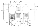
キャリアに入れた複数枚のフォトレジスト膜付ウェーハをオゾン酢酸液に浸漬して該膜を除去する装置の概念図を図1に示す。実験用に作られたドラフトは前室1、処理室2、後室3に仕切られており、全面にガラス戸があるが、操作時ドラフト内は外部と隔離され、すべての操作は外部でなされる。ウェーハ4が7枚入る石英ガラス製キャリア5を前室から処理室に入れ、また処理後後室を経てドラフトに取り出せるように、前室と後室には、処理室内のオゾンと酢酸を含む雰囲気をドラフト外に漏らさない為の空気置換機構(図示せず)と開閉出来る戸口6が設けられてある。
【0033】
石英ガラス槽7は酢酸中でオゾン処理を行う槽、石英ガラス槽8は酢酸リンス槽である。また、石英ガラス槽9はオーバーフローリンス槽で、超純水がバルブ10のある導入管11と排水管12で供給・排水されるようになっている。
【0034】
酢酸はバルブ13のある導入管14からリンス槽に供給され、リンス槽に満ちた酢酸は導通管15でオゾン処理槽7に入る。ウェーハ処理を経た酢酸はバルブ16のある排液管17で徐々に排液タンクに排出される。それぞれの槽の処理液の量は約5Lである。
【0035】
オゾン処理槽にはオゾンガスが石英ガラス管18により導入され、この管の先端部19は槽の底部に配置され、多数のガス発散用微細孔が設けられている。オゾンガスを2L/分で供給したところ、酢酸中のオゾン濃度は5分で200ppm以上に達した。
【0036】
レジスト膜800nmのウェーハをセットしたキャリアをロボットアーム20に前室で取り付け、オゾン濃度200ppm以上のオゾン酢酸槽に1分間浸漬し、次に酢酸リンス槽で1分リンスし、リンス槽上部に30秒放置して酢酸しずくが落下しウェーハ表面が薄い酢酸膜に覆われた状態に達したところで、超純水槽に移し3分間オーバーフローリンスして、後室でキャリアを取り出した。ウェーハをスピン乾燥して肉眼で検査したところ、全面でレジストの残っているところは見られなかった。
【0037】
ウェーハを2cm×2cmのチップに切断し、荷電粒子放射化分析を行ったところ表面有機炭素濃度は4×10¹⁴原子/cm2となった。レジストは除去されているが酢酸分子の吸着の他、メチルシリコン層の一部が残存している恐れがある。しかし、このオゾン酢酸処理はノボラック樹脂系レジストに対して、800nm/分以上の剥離能力即ちオゾン水処理により1桁以上強力な剥離能力があることになる。
【0038】
ドラフト内に発生した酢酸蒸気とオゾンガスは排気口21からファンにより排気され、図2の概念図のように排気処理される。槽7内の酢酸中のオゾン濃度が100ppmを越えるとオゾンによる青紫色は、鮮やかになる。色の濃さはオゾン濃度と正の相関があるので、光源22と受光部23により波長595nmの吸光度を測定して、オゾン濃度が所定値に達したらオゾンガスの供給を停止することにより、有害なオゾンの排出を最低限に管理することが出来る。
【0039】
排気口に続く排気管24は流出管25をもつ氷結室26で終わっている。氷結室は冷却するだけでなく、加熱も可能な熱交換器27に収納される。流出管は酢酸回収タンク28が脱着出来かつオゾン排気管29が付属する封管30の中に突出している。オゾン排気管には送風器31が連結され、本実施例の操作に際して密閉されたドラフトの中の雰囲気はこの送風器で排気された。この際熱交換器を稼働させて氷結室内を10℃以下に下げ、排気中の酢酸を室内で氷結させる。氷結した酢酸は一連の操作が終わった後、加温溶解してタンクに回収する。
【0040】
送風器を経た排気は低圧水銀灯による253.7 nm紫外線照射器に導入し、オゾン並びに僅かに残った酢酸を分解する。この実施例ではドラフト外の雰囲気中でオゾン臭並びに酢酸臭は全く感じられなかった。
【0041】
〔実施例2〕
実施例1のオゾン酢酸浸漬1分では有機炭素残存量がやや多かったので、浸漬を10分として同様にオゾン濃度200ppm以上で処理を行った。1.5μmレジスト膜に対して高ドーズ量のイオン注入を行ったウェーハも用い、下記6種類の試料にレジスト塗布のないウェーハをコントロールとして加えて、キャリアにセットした。尚、純水リンスは表面へ吸着した酢酸分子を除く目的で、1MHzの超音波振動子を下部に取り付けたオーバーフローリンス槽と交換して10分間処理した。
(1)800nmレジスト膜ウェーハ
(2)1.5μmレジスト膜ウェーハ
(3)30KeVでドーズ量1×10¹⁴/cm2のB+ イオン注入を行ったウェーハ
(4)(3)に1μmのアッシングを行ったウェーハ
(5)30KeVでドーズ量1×10¹⁵/cm2のB+ イオン注入を行ったウェーハ
(6)(5)に1μmのアッシングを行ったウェーハ
処理済のウェーハで、(5)の1×10¹⁵/cm2のみが明らかにレジストが残存していた他は、肉眼ではレジストは残存していなかった。しかし表面のダストカウントを行ったところ、1×1015/cm2イオン注入レジスト膜からの脱離レジストによる汚染が顕著であったので、改めて(5)の試料を除いて処理を行ったところ0.2μm以上の微粒子数は15個以下であった。荷電粒子放射化分析の結果は有機炭素量はすべて(7〜10)×1013原子/cm2で、1×1014/cm2イオン注入のものを含めてレジストは完全に除去され、メチルシリコン層も大部分が除かれたと推定される。
これらのウェーハに対してNH4 OH:H2 O2 :H2 O=1容:1容:12容のSC−1洗浄を後続させると、残存有機炭素量はすべての試料で(4〜7)×1012原子/cm2となりメチルシリコン層と吸着酢酸も完全に除去された。
【0042】
〔実施例3〕
オゾン酢酸のレジスト溶解能力が大きいことから、図3のようにオゾン酢酸を噴霧ノズル32で、ウェーハに供給し、液膜を流下させてレジスト除去を試みた。上下出来る蓋33で覆われるチャンバー34には、バルブ35でオゾンガスが供給出来る導入管36とオゾンガス排出管37があり、ウェーハ4をセットしたキャリア5が軸38により僅かな揺動をする台39が組み込まれている。バルブ40は処理済酢酸の排出管41にあって処理中は閉じられ、処理後に排出を行う。オゾンガスを2L/分でチャンバー内に導入すると共に、キャリアの揺動を行い、ウェーハ上に位置した噴霧ノズルからオゾン酢酸をウェーハ上に降り注ぐ。噴霧は最初はウェーハ全面が濡れるまで行い、その後はオゾン酢酸が各ウェーハの下端から滴下する程度に間欠的に行う。
【0043】
オゾン酢酸の噴霧は、インピンジャー構造の吸収容器42中のオゾン酢酸を3方コック43により電磁バルブ44を介してチッ素の圧力で噴霧管45に送入することにより行われる。オゾン酢酸は、予めバルブ46を介して導入管47と多孔ノズル48によりオゾンガスを1L/分で500mLの容器内酢酸に送り込みオゾンを吸収させて作成した。この酢酸はその導入管49とバルブ50で導入されたものである。
【0044】
レジスト剥離は実施例2に示した試料の(5)を除いて行われた。噴霧処理は間欠の停止時間を含めて10分、1枚あたり20ccの噴霧液量で施した。その後、導入管36からチッ素入酸素のみを流してウェーハ上の酢酸を乾燥させた。これらに対して、実施例2と同様にSC−1洗浄を行った所、残存有機炭素量はすべて(3〜7)×1012原子/cm2となり、また、0.16μm以上の粒子数はいずれのウェーハも10個以下であった。同様の処理を酢酸に代えてプロピオン酸で行った所、残存炭素量は酢酸の場合と有意差はなかった。
【0045】
〔実施例4〕
実施例2の試料(5)即ち1×10¹⁵イオン注入レジストに対し、実施例3と同様にオゾン酢酸噴霧処理を行った。ただし、酢酸に対し1/200容のフッ酸(49重量%)を添加した。10分、1枚当たり20ccの間欠的噴霧では、レジストはほとんど除去出来ていないが、明らかに脆化した。このウェーハに対し、超純水の高圧ジェットスプレーを行ってスピン乾燥したところ、酸化膜面上の水滴接触角は5°以下となった。これに対し、SC−1洗浄を行った所、残存有機炭素量は6×1012原子/cm2となり、高ドーズイオン注入レジストの除去が出来た。
【0046】
〔実施例5〕
前記各実施例に使用したものと同仕様の4枚の酸化ウェーハに対し、夫々に22Naで標識したNaを7×10¹¹原子/cm2、57Niで標識したNiを2×1011原子/cm2、59Feで標識したFeを5×1011原子/cm2、64Cuで標識したCuを5×1011原子/cm2の故意汚染を行った。この汚染は各元素の塩化物を水溶液と工夫された蒸発法でウェーハ表面におおむね均一になるように付着させ、140℃で脱水処理した。この後HMDSの塗布処理を行って、強い有機汚染のある場合の含フッ酸オゾン酢酸処理の金属汚染除去能力を調べた。
【0047】
実施例4と同様のフッ酸入オゾン酢酸で実施例3のように噴霧して3分で停止し、キャリア毎純水リンス付スピン乾燥装置で超純水リンス1分の後乾燥した。すべてのウェーハで水滴接触角が4°以下となり、HMDSによるメチルシリコン層が実質的に除かれていることが分かった。また各ウェーハの放射能の計測によりどの元素も3×10⁹ 原子/cm2以下となって、この処理が金属汚染除去にも有効であることが分かった。
【0048】
〔実施例6〕
前記各実施例で使用したものと同仕様のウェーハをフッ酸に浸漬して酸化膜を除いたものの裏面(エッチング仕上面)に対し、希フッ酸から半減期12.8時間でγ線を放射する64Cuで標識したCuを1×10¹¹原子/cm2吸着させ、さらにその裏面に対し、半減期が非常に長くβ線だけを放射する14Cで標識したDOPを1×1014分子(2.4×1015炭素原子)/cm2付着させた。この試料に対して実施例5と同様にフッ酸入オゾン酢酸処理と純水リンス・乾燥を行ってγ線の測定を行ったところ、Cuの残存量は2×109 原子/cm2であった。また64Cuからのβ線が消失した1週間後にβ線測定を行ってDOPの残存量を求めたところ、炭素濃度で7×1012原子/cm2であった。従って裏面に付着した有機物や金属等の汚染物質の除去にこのオゾン酢酸処理は効果が十分見られる。
【0049】
〔実施例7〕
希フッ酸のスピン洗浄・スピンリンス・スピン乾燥の出来る枚葉洗浄機を改造して図4のような枚葉スピンオゾン酢酸処理装置を作成した。スピン軸51をもつチャンバー52の蓋53には低圧水銀灯54を内蔵させた。C−200UZ3本を並列に使用した。水銀灯の184.9nm紫外線が損失なく支持具55に保持された被処理体ウェーハ56の表面に到達するように蓋の一部を合成石英ガラス板57とした。チャンバー52にはバルブ58で供給するオゾンガス導入管59と排出管60があり、またオゾン酢酸処理の間だけ回転してウェーハ中央に酢酸又はオゾン酢酸を滴下する酢酸導入管61と処理後超純水リンスを行う為の超純水導入管62が付属している。それぞれバルブ63と64で流入させる。
【0050】
実施例2に示した800nmレジスト膜の(1)試料とイオン注入後アッシングした試料(4)について、この装置でレジスト剥離を行った。いずれもウェーハの回転数を100rpmとし、オゾン濃度200mg/Lのオゾンガスを2L/分で供給した。酢酸導入管61から、実施例3に示したものと類似のオゾン吸収容器で作成した200ppm以上のオゾン酢酸を中央に流入し、ウェーハ全面が濡れたら約80滴を1分間で滴下させた。この後20秒超純水を流入させてスピンリンスし、オゾンの導入を停止してウェーハを4000rpmでスピン乾燥させた後、100rpmで1分間紫外線を照射した。ウェーハを荷電粒子放射化分析した結果、残存有機炭素は3及び5×1012原子/cm2でレジストもメチルシリコン層も十分に除去された。
【0051】
〔実施例8〕
前実施例で使用した図4の装置において、チャンバー蓋53に対し低圧水銀灯を設けずに単に蓋の機能をもたせ、一方超純水導入管62と同様の希フッ酸導入管を追加した。実施例2に示した800nmレジスト膜の(1)試料について前実施例と同様にオゾン酢酸処理と純水リンスを行った後、希フッ酸(フッ酸:水−1容:50容)のリンスを15秒、純水リンスを15秒行った後、前実施例同様にスピン乾燥した。残存炭素量は1×10¹³原子/cm2で前実施例より若干レベルは高いがデバイス製造で十分実用出来る吸着分子除去がなされている。
【0052】
〔実施例9〕
実施例6のように酸化膜を除いたウェーハに対してSC−1処理を行い14C標識DOPをヘキサンに溶解して全面に塗布し、ヘキサンを急速に蒸発させてDOP濃度1×10¹⁴分子/cm2の故意汚染試料を作成した。
実施例7の装置を用い、導入管61から純度99%のプロピオン酸を導入し、同実施例と全く同様に1分間の処理と純水リンス・紫外線照射を行った。ただしウェーハの回転数は50rpm、ウェーハが濡れた後の滴下量は50滴とした。処理終了後放射能測定を行ったところ、残存DOPは2×10¹¹分子(5×10¹²炭素原子/cm2)で、DOPは十分に除去出来た。
【0053】
〔実施例10〕
本発明による液膜処理を蒸気洗浄機構で行った場合の実施例を図5により説明する。上下出来る蓋65とし、ジクロロメタン液を底部66に溜め、それを加熱して蒸気化する加熱器67と、液の上方にセットしたキャリア68入りの板状ガラス被処理体69を冷却する冷却管70を装備したチャンバー71とでこの装置は構成されている。この装置の特色はバルブ72を備えたオゾンガス導入管73とオゾンガス排気管74が設けられていることである。該導入管の先端はオゾンガスの微細泡を液内に発生させ、オゾンとジクロロメタンの混合ガスを作る多孔管75に接続している。装置はステンレス鋼の板と管で作られた。
【0054】
レンズ研磨用のピッチを塗布したガラス板を故意汚染試料としてキャリアにセットし、約200mg/Lの濃度のオゾンガスを2L/分で流しながら、ジクロロメタンの蒸気洗浄を行い、ジクロロメタンだけの蒸気洗浄と比較した。いずれも10分で乾燥状態に仕上げ、水滴接触角を測定したところ、オゾンを使わない場合の30〜35°から約10°以下になった。この後でC−200UZによる紫外線照射を2分行ったところ水滴接触角は3°となった。ジクロロメタンだけの洗浄品ではこの角度を得るのに紫外線照射は20分以上を要した。
【0055】
〔実施例11〕
実施例9のキャリアにメッキ前処理として油性汚れの除去の必要な鉄板をセットし、同実施例と同様に蒸気洗浄処理と2分間紫外線処理を行ったところ、水滴接触角は洗浄前の55°から 4°となった。
【0056】
〔実施例12〕
200mg/L〜300mg/Lの高濃度オゾンが0.5〜1L/分の流速で得られるオゾン発生装置を準備した。石英製ガラスフィルターをノズル端にした石英ガラス製インピンジャー(容積100mL)に水を比率を変えて添加した酢酸を満たし、該発生装置で作成したオゾンを220mg/L含む1%窒素含有酸素ガスをバブリングさせ、5分後オゾンが飽和したものとして液に溶解したオゾン濃度を測定した。定量法はオゾンでヨウ化カリウムがヨウ素に変る反応を利用した容量分析法である。図6の点線は含水酢酸の酢酸濃度と得られた飽和オゾン濃度との関係を示す(液温は20℃)。
【0057】
オゾン飽和含水酢酸の酢酸濃度と、このオゾン飽和酢酸のノボラック樹脂系レジストIX555(JSR(株)製)に対する剥離速度との関係を求めたのが図6の実線である。この関係を求める実験は次のように実施された。
前述したようにしてHMDS塗布処理を行った100nm酸化膜ウェーハに対し、上記のIX555を1.5μmの厚さに塗布し、140℃,60秒のベーキングを行った試料を2cm×2cmの四角に切断し、小型石英ビーカの底において、上記オゾン飽和酢酸を10mL加え、揺動して肉眼でレジストが完全に剥離する時間を求め、その値から剥離速度を計算したものである。
この図から220mg/Lのオゾンガスを使うと、オゾン飽和量は380mg/Lで、98%以上の純度の酢酸のノボラック樹脂系レジストIX555に対する剥離速度は6μm/分以上にも達することが分る。本発明において、酢酸中のオゾン濃度が400mg/L近くなると、1.5μmの厚さのレジスト膜は15秒程度の極めて短時間に除去出来ることになる。
【0058】
〔実施例13〕
前例のようにオゾンガスの濃度の濃度を高め、オゾン発散用にガラスフィルターを使うと容易にオゾン400ppm程度の高濃度の酢酸が得られ、30秒以下の接触でノボラック樹脂系レジストの除去が出来るので、このような高オゾン濃度酢酸による処理は枚葉スピン洗浄機構の利用が好適と言えよう。そこで、実施例7の枚葉スピン洗浄機構を用い、図7に断面図を示すレジスト除去装置を作成した。
【0059】
枚葉スピン処理における被処理体ウェーハ56は、その支持具55がスピン回転軸51により回転機構76で駆動されスピン回転するようになっており、スピン処理時に飛散する処理液を回収するチャンバー52に囲まれている。この枚葉処理機構と、被処理ウェーハのすべてを収納するウェーハカセット77の支持台78と、このカセットと支持具55の間でウェーハを自動的に出入れする搬送ロボット79とが、防爆型の筐体80内に具備されている。尚、ウェーハ出入時にはチャンバーの壁面の一部81が自動的に開く機構を設けておく。この筐体の壁には、該ウェーハ表面にオゾン酢酸を放出するノズル82を末端とした処理液供給管83と、リンス用の酢酸を放出するノズル84を末端とした酢酸供給管85とが貫通している。尚、この2個の供給管は弁操作で1本にまとめることも出来る。
【0060】
また、チャンバー底に溜った酢酸が排出する液排出管86と、筐体内の雰囲気を置換する為の気体導入管87と、Mnのような触媒を使ったオゾン分解器(図示せず)に送気するオゾン排気管37とが筐体壁面を貫通している。尚、筐体にはウェーハカセットを出入れする開閉可能な戸6が設けられ、筐体内雰囲気からオゾン並びに酢酸が排出されている場合にのみ開閉を行う。
オゾン酢酸液はオゾン吸収容器42内に溜められた酢酸88に対し、石英製ガラスフィルターのオゾン発散器89にオゾンガスをバルブ58を経た配管59で送入することにより作成することが出来る。通常は5分の通気でほぼ飽和オゾン濃度となる。この液はPと表示されたテフロン製送液ポンプとFと表示されたダスト用精密フィルターを通して供給管83で所定時間ノズル82まで送液される。酢酸のオゾン吸収容器への供給並び容器からの排出はバルブ90を有する配管91で行う。リンス用の酢酸92は別の容器93にバルブ94を有する配管95で供給する。リンス液は送液ポンプとダスト用精密フィルターを経由する配管85でリンスノズル84に所定時間送られる。
【0061】
100nm酸化膜の6″ウェーハに前述のようにHMDSを塗布してフォトレジストIX555の1.5μmの膜を形成し、140℃で60秒ベークしたものを25枚準備し、図7のようにカセットに入れてセッティングした。
オゾン酢酸はオゾン吸収容器42に酢酸を約300mL入れ、220mg/Lのオゾン濃度の窒素入り酸素を1L/分の流速でオゾン発散器からバブリングさせると、約5分で最高濃度380mg/Lに達する。ウェーハ56を1000rpmを回転させ、オゾン酢酸をノズル82から1.5mL/秒の速さで放出したところ、肉眼では15秒で全面のレジストが剥離された。さらに20秒放出を続け、酢酸容器93中の酢酸をノズル84から1.5mL/秒の速さで10秒リンスし、ウェーハの回転を4000rpmに上げて30秒スピン乾燥した。カッセット内ウェーハと交換して25枚連続で処理したが、オゾン吸収容器中のレジスト分解残が蓄積する筈であるにも拘らず、肉眼的剥離所要時間約15秒は最後まで変らなかった。
【0062】
ウェーハの剥離をすべて終えたカセットを筐体から取出し、通常の洗浄装置で10分間の超純水オーバーフローリンスの後スピン乾燥し、これらのウェーハから2cm×2cm角のチップを切り出して、荷電粒子放射化分析で残存有機炭素量を調べたところ(0.8〜2.6)×1013原子/cm2で、レジストのみでなくHMDS膜もほとんど除去されていることが分った。
このように処理液の劣化がみられないのは、枚葉処理後の廃オゾン酢酸液がオゾン飽和容器に戻った時、高濃度のオゾンが常に存在する為、溶解したレジストの分解が強力に進行して再使用に十分な純度レベルに純化が進み、一方酢酸は高濃度のオゾンでも殆ど変化しない為と考えられる。即ちこの処理法では処理液の循環再使用が可能で、新たに必要な酢酸はリンスに使われるもののみともいえる。リンス液分は吸収容器中の液量が増える為、バルブ90によって徐徐に排出させる。しかし排出分の酢酸純度も高いので、蒸留により極めて高い回収率で回収され、リンス用に供することが出来る。
【0063】
〔実施例14〕
呼吸器系の医学診断用に使われるテクネガス装置は、0.1μm以下の超微粒の炭素ダストを分散したアルゴン雰囲気を作成する装置で、この微粒子は半減期6時間の99mTcで標識されている。この装置で前実施例に使用したレジスト膜付ウェ−ハの膜面を汚染させ、イメージングプレートを使用して全面の付着炭素粒子による放射線量をラジオルミノグラフィで求めたところ2600PSL/cm2の放射能があった。放射線実験専用の枚葉実験器を作り、前実験と同じオゾン濃度の酢酸液で同様の剥離条件でレジストを除去し、酢酸リンス・乾燥の後、同様のラジオルミノグラフィ測定を行った。残存炭素粒子に基づく放射線量はバックグランドの20PSL/cm2以下であった。このオゾン酢酸処理は微粒子除去にも有効であることが分った。
【0064】
〔実施例15〕
ヘンリーの法則により、酢酸中で発散させるガス中のオゾン濃度に比例してオゾン酢酸液のオゾン濃度も増加する。酸素中のオゾン濃度が280mg/Lに増した場合の含水酢酸中の酢酸濃度と飽和オゾン濃度の関係を計算して図6に破線で示す。
酢酸濃度が80容量%に下がると装置の防爆が不要となって構造上の利点が多い。水分この程度あっても発散させるガス中オゾン濃度を280mg/Lとすると酢酸中のオゾン濃度は250ppmとなり、ノボラック樹脂レジストの剥離速度は1μm/分程度となって、枚葉スピン処理も可能となる。
レジスト膜を膜厚800nmのノボラック樹脂レジストIQ2002(東京応化工業(株)製)として、酸素中のオゾン濃度を280mg/L、酢酸を両容器共に80容量%(残り水)としオゾン酢酸の放出時間を1分とした他は、実施例12とまったく同様に実験した。
肉眼的なレジスト剥離時間は平均45秒であった。実施例12と同様に処理して残存有機炭素濃度を測定したところ、すべて3×10¹³原子/cm2以下で、HMDS層も大部分除去出来ている。さらにこの後でSC−1処理を行ったところ、残存有機炭素濃度は5×1012原子/cm2以下で、十分過ぎるといえるほどの清浄度が得られた。
【0065】
【発明の効果】
半導体のリソグラフィ工程で酸化膜上のポジ型レジストをその密着剤HMDSに由来する界面のメチルシリコン層を含めて、残存有機炭素量が1013原子/cm2以下まで除去しようとすると、従来の方法では組成が十分に管理されたピラニア処理を行い、SC−1処理を後続させねばならない。ピラニア処理は130℃前後の高温処理が必要で、その成分のH2 O2 は分解してH2 Oとなって液が薄まって効果が低下する他、その際硫酸がミストとなって飛散するので、環境汚染対策が重要な問題となっている。本発明はオゾン処理の為、密閉系が必要であるが、排気のオゾンガスは容易に分解出来、また酢酸等の有機溶剤は処理が室温なので飛散量が少なく、かつ酢酸をつかう場合は分解処理の前の冷却で回収出来る。本発明において除去処理の後のオゾン酢酸液をオゾンをバブリングさせるオゾン溶解(吸収)液に復起させれば、オゾンの被処理汚染物質例えばノボラック樹脂系レジストを分解する能力が強いので、このレジストの場合、樹脂はムコン酸等からマレイン酸等を経て、感光剤のナフトキノンアジドはフタル酸等を経て、グリオキザールとグリオキシル酸に分解し、最終的にはギ酸から水と炭酸ガスに分解する。即ちこのオゾンバブリングの過程で精製が行われ酢酸は長寿命で使われる。要するに有機溶剤はオゾンで純化され、単に溶解するだけの他のレジスト除去剤が溶解物を蓄積して劣化するのに比し、使用量が極めて少くて済み、経済性に優れた効果がある。従って本発明においてはオゾンもこのような有機溶剤も環境汚染への対策が容易である。特に酢酸は毒性が非常に弱いので安全性が高い。
【0066】
またピラニア処理や従来のオゾン処理に比し、本発明の処理法はこのようなレジストに対する剥離速度が1桁〜2桁速い。これは本発明に使用する有機溶剤のオゾン溶解度が水の約10倍であり、かつこれらの有機溶剤がオゾンで分解しにくい為である。かつこれらの有機溶剤は表面張力が小さく、容易に被処理体表面に拡がるので、高オゾン濃度の有機溶剤液膜で被処理体表面を効率よく処理出来る。従って少い液量で処理出来、液膜中のオゾン濃度を出来るだけ高く保つ為に液膜処理をオゾン雰囲気中で行うので、オゾンガスの使用量もオゾン水処理の場合より少くて済む。
【0067】
本発明のポジ型レジスト剥離能力は極めて強いので、1×10¹⁴/cm2B+ イオン注入レジストは容易に溶解し、1×10¹⁵/cm2注入レジストでも、後に高圧ジェットスプレー洗浄を行えば十分除去出来る程の化学作用(脆化)を与えることが出来た。イオン注入層をアッシングしたレジストでは、1分間の枚葉オゾン酢酸液膜処理で除去することも可能である。しかも液の表面張力が小さいので、微細パターンのあるデバイス製造工程ではパターンの隅々まで容易にレジスト除去効果が及び、微粒子もよく除去出来る。また高濃度のオゾンによる強い酸化力をもった酸処理の為、金属汚染も除去出来るなど、種々の汚染物質の除去に効果があり、洗浄剤としての利点も備えている。
【0068】
本発明の処理で吸着した酢酸等のカルボン酸分子は後続する純水リンスの際イオン化する。イオン化したこれらの分子は酸化されやすく、例えば紫外線オゾン処理では極めて短時間に分解して消失し、この他アルカリ−過酸化水素処理でも同様で、本発明は容易に表面有機炭素濃度を1012原子/cm2のオーダーまで到達させる清浄化効果を有している。
【0069】
本発明のオゾン雰囲気中のオゾン有機溶剤の移動液膜処理の効果は、オゾンの溶解度が高くてかつ表面張力が小さく毒性も比較的少ないジクロロメタンの蒸気洗浄へ簡単に応用が出来る。この処理は短時間紫外線オゾン処理との組み合わせで、水の付着が好ましくない場合の有機物等の汚染物質の高度な除去を簡便化する効果がある。
【0070】
【図面の簡単な説明】
【図1】本発明を被処理体の浸漬で行う場合の概念図。
【図2】酢酸を含むオゾン排ガスの処理に関する概念図。
【図3】本発明のオゾン酢酸液噴霧による液膜流下方式処理装置の縦断面図。
【図4】本発明のオゾン酢酸液滴下による枚葉液膜移動式処理装置の縦断面図。
【図5】本発明のオゾン雰囲気中のジクロロメタン蒸気洗浄装置の縦断面図。
【図6】実施例12で得られた、含水酢酸の酢酸濃度と飽和オゾン濃度との関係(点線:オゾン濃度220ppm、一点鎖線:オゾン濃度280ppm)、及びオゾン飽和含水酢酸の酢酸濃度とノボラック樹脂系レジストに対する剥離速度との関係(実線)を示す。
【図7】本発明によるレジスト除去装置を説明する概念図。
【符号の説明】
1.ドラフト前室 2.ドラフト処理室 3.ドラフト後室
4.被処理体ウェーハ 5.ウェーハ用キャリア 6.開閉出来る戸
7.オゾン酢酸処理槽 8.酢酸リンス槽 9.純水リンス槽
10.純水用バルブ 11.純水用導入管 12.純水用配水管
13.酢酸用バルブ 14.酢酸用導入管 15.酢酸導通管
16.排液管用バルブ 17.排液管 18.オゾンガス導入管
19.オゾン発散管 20.キャリア移動用ロボットアーム
21.ドラフト排気口 22.オゾン比色用光源 23.オゾン比色用受光部
24.排気管 25.溶解酢酸流出管 26.酢酸氷結室
27.冷熱用熱交換器 28.酢酸回収タンク 29.オゾン排気管
30.タンクキャップ封管 31.送風器 32.オゾン酢酸噴霧ノズル
33.チャンバー蓋 34.チャンバー 35.オゾンガス用バルブ
36.オゾンガス導入管 37.オゾンガス排出管 38.キャリア揺動軸
39.キャリア揺動台 40.酢酸排出用バルブ 41.酢酸排出管
42.オゾン吸収容器 43.3方コック 44.チッ素圧送用電磁バルブ
45.オゾン酢酸噴霧管 46.オゾンガス用バルブ47.オゾンガス導入管
48.オゾンガス発散ノズル49.酢酸導入管 50.酢酸用バルブ
51.スピン洗浄機スピン軸52.チャンバー 53.チャンバー蓋
54.低圧水銀灯 55.ウェーハ支持具 56.被処理体ウェーハ
57.合成石英ガラス板 58.オゾンガス用バルブ59.オゾンガス導入管
60.オゾンガス排出管 61.酢酸導入管 62.純水導入管
63.酢酸用バルブ 64.純水用バルブ 65.チャンバー蓋
66.ジクロロメタン液溜 67.加熱器 68.被処理体用キャリア
69.板状被処理体 70.冷却管 71.チャンバー
72.オゾンガス用バルブ 73.オゾンガス導入管 74.オゾンガス排出管
75.オゾンガス発散管 76.回転機構 77.ウエーハカセット
78.支持台 79.搬送ロボット 80.筐体
82.ノズル 83.処理液供給管 84.ノズル
85.酢酸供給管 86.液排出管 87.気体導入管
88.酢酸 89.オゾン発散器 90.バルブ
91.配管 92.リンス用酢酸[0001]
TECHNICAL FIELD OF THE INVENTION
The present invention relates to a method for cleaning articles requiring removal of contaminants, and more particularly to a method for cleaning a substrate for an electronic device. More specifically, the present invention relates to the removal of an organic film such as a photoresist used for processing a semiconductor wafer or a liquid crystal substrate, and cleaning of organic contamination generated throughout the wafer process. . More broadly, the present invention relates to cleaning organic contamination of precision metal and glass workpieces.
[0002]
[Prior art]
The removal of the photoresist used for the microfabrication on the oxide film or the polysilicon film is usually performed using a mixture of sulfuric acid (3 or 4 volumes) and hydrogen peroxide (1 volume) (called piranha) for 110 days. A method of heating to 140140 ° C. and immersing for 10 to 20 minutes is used. When high-concentration ion implantation is performed using a resist mask, the resist is deteriorated and cannot be removed by piranha treatment. Therefore, ashing using plasma-excited oxygen is widely used. However, ashing all of the photoresist leaves trace metal from the resist on the wafer surface and harmful devices to the wafer surface due to the high energy plasma. Therefore, ashing is performed while leaving the resist film, and thereafter, the resist is removed by piranha treatment. Attempts have been made to mix ozone instead of hydrogen peroxide in this piranha treatment, but because of the low solubility of ozone, a longer treatment is required for removal and it is rarely used.
[0003]
Recently, a resist removal method using ozone water has appeared. The solubility of ozone in water increases as the temperature decreases, and the amount of dissolved ozone reaches 70 to 100 ppm in ultrapure water at about 5 ° C. When the resist is removed with such low-temperature and high-concentration ozone water, a 800 nm-thick positive-type novolak resin-based photoresist film widely used in LSI manufacturing can be stripped in about 10 to 15 minutes. (Peeling rate: 70 to 80 nm / min).
Organic substances such as dioctyl phthalate (DOP), siloxanes, and hexamethyldisilazane (HMDS) contaminate the surface of silicon wafers and oxide films from the atmosphere in a clean room for semiconductor device production, which degrades device characteristics. It is known that the device yield is reduced.
[0004]
As a wet cleaning method for removing organic substances on a silicon wafer or an oxide film, the above-mentioned piranha treatment has been most effective. However, SO4 2-Remains on the wafer and generates fine particles under the influence of the environmental atmosphere, which tends to cause haze. To remove this completely, usually SC-1 treatment (standard composition is NH4OH: H2O2: H2O = 1 volume: 1 volume: 5 volume) and the like. The SC-1 treatment alone has the effect of decomposing and removing organic substances, and the effect of removing fine particles has hitherto been the most effective. However, in SC-1, Fe, Al, Ca, Mg, Zn, Ni, and the like in the chemical liquid easily deposit on the wafer during cleaning, and it is difficult to control the cleanliness of the chemical liquid and the cleaning tank. Therefore, the SC-2 treatment (standard composition is HCl: H), which is considered to have excellent metal removing ability except for the chemical oxide film generated by the SC-1 treatment with rare HF.2O2: H2(O = 1 volume: 1 volume: 6 volumes) is a common means of semiconductor cleaning, and is called an RCA method. Surface residual SO4 2-Although a method of performing a large amount of heating water rinsing for a long time has been used to remove, the achievable cleanliness is inferior when the normal RCA method is followed.
[0005]
As a cleaning method for organically contaminated wafers, conventional treatments relying on piranha treatment are not satisfactory in terms of economy, productivity and safety. Ozone water has emerged as a new cleaning method to solve these problems. At room temperature, 20 to 30 ppm of ozone water can be obtained, so that the oxidizing power is used to remove organic contamination of the wafer.
[0006]
[Problems to be solved by the invention]
With the advancement of semiconductor devices, especially VLSI, reduction of organic contamination on the wafer surface is becoming more and more important. Until recently, there was no mention of surface organic carbon concentration in the roadmap published by the Semiconductor Industry Association of America. 1x10 was announced at the end of 199714Atom / cm2Organic carbon concentration is allowed, but in 2009 this concentration was 1.8 × 10ThirteenAtom / cm2Is in need. This cleanliness is, of course, necessary even after the resist is stripped. The piranha cleaning liquid is repeatedly used in terms of economy, but if the methyl silicon layer on the oxide film generated by the positive resist adhesive HMDS is to be removed to such a high cleanliness level, the piranha cleaning liquid deteriorated by repeated use. Then it becomes difficult, so the number of uses must be severely limited. Therefore, the use amount of sulfuric acid is increased, which not only deteriorates economic efficiency but also complicates wastewater treatment.
Since the removal of the resist on the metal film is damaged by a strong acid treatment, the film is damaged by using N-methylpyrrolidone (NMP) as a remover at about 70 ° C. for about 15 minutes. In this case, ultrapure water rinsing is performed after rinsing with an organic solvent such as isopropyl alcohol. This treatment requires a large amount of an organic solvent, is not desirable in terms of economy, and is expensive in wastewater treatment.
[0007]
Accordingly, although ozone water treatment is expected, semiconductor-grade high-purity ozone water is produced by absorbing high-purity gas containing ozone into ultrapure water. By the way, when a gas containing ozone is injected into a container containing a liquid, the concentration of ozone in the gas becomes CG[Mg / L], the concentration of ozone in the saturated liquidLす る と [mg / L], distribution coefficient D = CL/ CGIt becomes. Here, in the case where the liquid is water, in a certain research example, D = 0.28 at 25 ° C., D = 0.28 at 20 ° C., and D = 0.47 at 5 ° C., which is a normal high purity. Since the ozone concentration obtained by the ozone gas generator is about 200 mg / L, the saturation concentration is calculated to be 40 ppm at 25 ° C. and 94 ppm at 5 ° C. In practice, as described above, a concentration slightly lower than this concentration can be obtained. Moreover, ozone is easily decomposed in water, and the maximum level of ozone in the ozone water washing tank cannot be maintained unless ozone gas is constantly circulated and ozone gas is injected. In addition, if there is an obstacle to the flow such as a wafer carrier in the cleaning tank, a portion where ozone is insufficient on the wafer surface is formed, and the resist peeling speed decreases. Even if the stripping speed of the resist itself is about 100 nm / min, it is twice as long as the processing time calculated from the stripping speed to completely remove the methyl silicon layer from all the wafers in the wafer carrier. Need more. That is, it takes 20 to 30 minutes to remove the 1 μm-thick resist film.
[0008]
According to the present invention, the immersion type resist stripping including the complete removal of the resist adhesive is shortened, and the carbon amount of the surface after the treatment is reduced to 10%.12Atom / cm2The present invention provides a cleaning method which can be reduced to the order of 1) and is effective as a photoresist removing method.
[0009]
The organic matter found in the largest amount on a wafer in a semiconductor clean room is usually DOP, which often exceeds 200 ng on a 6 ″ wafer surface. This DOP forms a fine spot-like oil film on the wafer surface. The contaminant particles adhered to the surface are strongly captured by the liquid film of the oil film, making it difficult to remove by cleaning, a phenomenon that is significantly more significant on the back surface of the wafer than on the front surface. This is because, in the device manufacturing process, the back surface of the wafer may be treated in contact with another material like a vacuum chuck, and since this material surface is usually lipophilic, it is contaminated with DOP or the like and transferred. In the semiconductor device manufacturing process, the back surface of a wafer may face the front surface of an adjacent wafer, and a large number of wafers may be processed at the same time. At this time, the influence of organic matter contamination and fine particle contamination on the back side reaches the device forming surface facing the surface, and it is known that if there is contamination by DOP or the like, the removal of metal contamination is hindered in the cleaning process. The adverse effects include metal contamination.
[0010]
Therefore, the present invention also provides a method of cleaning a substrate surface capable of strongly removing contaminant contaminants on the front and back surfaces of a wafer and removing contaminant metals. Further, since this organic contamination removal is extremely powerful and environmental pollution can be easily controlled, the present invention provides a cleaning method applicable to cleaning bodies other than electronic device substrates.
[0011]
[Means for Solving the Problems]
In order to achieve this object, the present invention provides a treatment in which ozone is dissolved in an organic solvent having a distribution coefficient of 0.6 or more in a gas on an organic solvent having a distribution coefficient of 0.6 or more on the surface of a treatment object to which contaminants are attached. It is an object of the present invention to provide a method for removing contaminants adhering to a surface, which comprises contacting a liquid to remove contaminants adhering to the surface of the object.
[0012]
BEST MODE FOR CARRYING OUT THE INVENTION
Further, according to a preferred embodiment of the present invention, a liquid film of the processing liquid is formed on the surface of the processing object to which the contaminant adheres, and the processing liquid is continuously or intermittently added to the liquid film. The method for removing contaminants adhering to a surface is characterized in that the surface of the object to be treated is brought into contact with the ozone-containing treatment liquid by supplying a liquid film and moving the liquid film.
[0013]
This is because a particular organic solvent such as acetic acid dissolves ozone about 10 times more than water, as described below, and the liquid film is also in an amount sufficient for the ozone therein to act on surface-attached contaminants. It depends. If the ozone concentration in the atmosphere in contact with the liquid film is higher than the equilibrium concentration with ozone in the liquid, the ozone easily diffuses into the liquid film and the ozone concentration of the liquid rises to near saturation in a short time.
[0014]
Therefore, the present invention, as another preferred embodiment of the above method, in an atmosphere containing ozone, a liquid film of the organic solvent is formed on the surface of the object to which the contaminant is attached, and the film is continuously or intermittently formed. The present invention provides a method for removing surface-attached contaminants, which comprises contacting the surface of an object to be treated with an ozone-containing treatment liquid by supplying a new solvent to the liquid film and moving the liquid of the film. is there.
[0015]
In the present invention, upon removal of the surface-attached contaminants, the ozone-containing organic solvent liquid after the removal treatment is united with the organic solvent for dissolving ozone, and supplied as a removal treatment liquid for the object to be treated. The present invention provides a processing method and an apparatus for circulating water. Non-polar organic solvents such as acetic acid are less likely to be decomposed by ozone. For example, acetic acid is one of the most stable substances to ozone in a common organic solvent, and has high solubility in ozone. This dissolved ozone has a strong reactivity with organic substances having an unsaturated bond and has not only a decomposing effect, but also a carboxylic acid or carbon dioxide gas which is finally stable to ozone if sufficient reaction time is obtained. Decomposes into water. That is, in this circulation process, purification necessary for the removal treatment is performed, and the life of the removal treatment liquid can be extended. The most characteristically effective treatment of the present invention is provided which is extremely economical.
[0016]
The supply of the organic solvent liquid may be performed by spraying the liquid, and in this case, the movement of the liquid on the membrane may be caused to flow down or by centrifugal force. This liquid supply may be performed by liquefying the vapor generated from the heated liquid on the surface of the object to be cooled.In this case, the contaminant is removed by the vapor cleaning mechanism by the flow of the condensate. Will be removed. The present invention also provides an apparatus for removing contaminants adhering to the surface of an object, in which the liquid film on the surface of the object is moved in a chamber into which ozone gas is introduced by supplying the organic solvent liquid.
[0017]
In the present invention, when the contaminants attached to the surface of the object to be treated are removed by the organic solvent, the organic solvent molecules are slightly adsorbed on the surface of the object to be treated. However, the adsorption amount is (10Thirteen-1014) Atoms / cm2It will be a low level. This is because even though the organic solvent contained in the contacted solution is an organic substance, the molecule contains few carbon atoms and has an extremely high concentration of coexisting ozone. This is a feature of the present invention. In addition, the adhesion of the organic matter adsorbed to the object to be processed is weak, and the carbon concentration can be easily reduced to 10 by the oxidizing treatment.12Atom / cm2Can be further reduced to lower orders. The oxidizing treatment includes, for example, oxidizing cleaning such as alkali / hydrogen peroxide cleaning, or oxidizing treatment with ozone under irradiation of ultraviolet rays of 184.9 nm and 253.7 nm. Further, when the surface of the object to be processed is made of a silicon oxide film, the adsorbed molecules can be removed to a carbon concentration level close to this by a slight peeling of the surface layer by dilute hydrofluoric acid.
[0018]
The organic solvent used in the present invention and having a partition coefficient with ozone in the gas of 0.6 or more is generally a non-polar organic solvent. The partition coefficient (D) is the partition coefficient of ozone between the organic solvent in the liquid phase in the standard state and the inert gas in the gas phase in contact with the organic solvent. That is,
D = saturated ozone concentration in organic solvent (mg / L) / equilibrium ozone concentration in gas (mg / L)
Indicated by
The partition coefficient of the organic solvent used in the present invention is preferably 1.0 or more, more preferably 1.5 or more, and further preferably 2.0 or more.
Any organic solvent having a partition coefficient with ozone in a gas of 0.6 or more can be used in the present invention without any particular limitation.
Formula: CnH2n + 1(COOH) a fatty acid represented by [n = 1 or an integer of 3 or 3] and dichloromethane, and particularly preferably the fatty acid. The fatty acids include acetic, propionic and butyric acids. These organic solvents can be used alone or in combination of two or more.
[0019]
In the present invention, the ozone concentration in the treatment liquid is 100 ppm or more, and more preferably 200 ppm or more. If the ozone concentration is less than 100 ppm, a sufficient pollutant removing action may not be obtained.
Since the fatty acid having a purity of 99.7% as described above has an approximate D of 1.9 at 25 ° C., an ozone liquid having a concentration approximately 10 times higher than that of pure water can be obtained. Therefore, it shows much higher pollutant removal ability than ozone water. The removal treatment may be immersion in an ozone solution, but it is preferable to use an organic solvent having a very small surface tension of 30 dyn / cm or less for treatment with the liquid film. The liquid easily spreads like a film over the entire surface of the object. Here, when the liquid moves, the surface contaminants acted on by the liquid also move at the same time, and efficient removal progresses. Also, the fine particles caught by the attached organic matter are easily removed because the organic matter dissolves in the liquid having a small surface tension and the liquid moves.
[0020]
Among these carboxylic acids, acetic acid with n = 1 is preferred, because it is cost-effective, a high-purity commercial product is easily available, and there is almost no problem in terms of toxicity. Although the melting point is 16 ° C., it is difficult to handle. However, there is no problem at a normal clean room temperature, and there is an advantage in recovery as described later. Since propionic acid with n = 2 has a melting point of −20 ° C., the action of the acid is weakened and the ozone can be processed at a high temperature and the low-temperature treatment can be performed on the object which is easily attacked by the acid. Butyric acid with n = 3 has a flash point of 72 ° C., which is about 20 ° C. higher than acetic acid or propionic acid. When it is desired to promote the reaction by heating, a treatment at about 70 ° C. can be performed without danger.
[0021]
Acetic acid containing a small amount of water is easier to dissolve inorganic salts, and has a lower coagulation temperature and is easier to use. A sufficiently high concentration ozone liquid can be obtained with a purity of 97% even at D = 1.7, 95% at D = 1.5, 90% at D = 1.3, and 85% at D = 1.1. Therefore, by adding water containing 5% by volume or less of an inorganic acid, especially hydrofluoric acid, to acetic acid, metal contaminants can be removed well at the same time. Since such a high D value can be obtained, when ozone gas obtained by a high-purity ozone gas generator is bubbled from a large number of micropores into acetic acid having a purity of 85% or more, even if the ozone concentration is about 100 mg / L, the ozone concentration can be easily obtained. Is 100 ppm or more, which can be provided to the present invention. When an ozone gas having an ozone concentration of 200 mg / L is used, the ozone concentration of the liquid becomes 200 ppm or more in several minutes.
If a glass filter is used as a divergent device for bubbling ozone gas, it can reach a concentration close to saturation in about 5 minutes, and the ozone concentration can be enhanced to nearly 400 ppm.
[0022]
When ozone gas having an ozone concentration of 300 mg / L is used, the ozone concentration of the liquid increases proportionally according to Henry's law. The ozone concentration in the liquid is 200 ppm or more, and the effect of the removal treatment of the present invention can be sufficiently obtained. The blue-violet color of the liquid having such an ozone concentration becomes extremely sharp. Since the color density has a positive correlation with the ozone concentration, the ozone concentration of the liquid can be controlled to a predetermined value by simple colorimetry.
[0023]
When it is not desired to use an acid or a water-soluble solvent which may cause rust after the treatment, dichloromethane is preferred as the organic solvent. When D = 2.0, ozone is hardly decomposed and toxicity is relatively low. Further, dichloromethane is suitable for carrying out the present invention by a steam cleaning mechanism, and when carried out with a mixed solution with acetic acid, the effect of removing contaminants is further enhanced.
[0024]
When a carboxylic acid is used in the present invention, a substrate for electronics industry is most suitable as the object to be processed. Adhered contaminants generated by adsorption from an environmental atmosphere or contact with an organic material can be easily removed. In particular, the positive type novolak resin resist on the silicon oxide film can be removed at a peeling rate of 1 μm / min to 6 μm / min, which is almost two orders of magnitude higher than the conventional one. In the case of dichloromethane, the object to be processed is preferably a metal processed product or a glass processed product, and a cleaned surface having a superior water droplet contact angle evaluation can be obtained as compared with the case of using alone for removing oily dirt, pitch and wax. The shape of the object to be processed is preferably a plate shape, but may be any shape as long as the movement of the liquid film is not largely uneven.
[0025]
In order to carry out the present invention, it is necessary to perform treatment in an airtight chamber or a draft so that harmful ozone gas does not pollute the ambient air. Since the treatment is performed at room temperature, vaporization of the organic solvent is relatively small, but contamination of the outside world due to the vaporization can be prevented at the same time. The exhaust pipe from the hermetic chamber is connected to an ozone decomposer utilizing ultraviolet irradiation of a wavelength of 253.7 nm or alkali solution treatment. If a cooling mechanism is provided in the exhaust system, the organic solvent can be liquefied and recovered. When acetic acid is used, it easily freezes, so that a high recovery rate can be obtained. Therefore, the present invention can be implemented with almost no pollution of the environment.
[0026]
When the wafer is placed in a carrier and immersed in ozone-containing acetic acid for the resist removal treatment according to the present invention, the effect of the carrier as in the case of immersion in ozone water is small because the resist removal rate is high, and the resist is uniformly removed to the periphery. I can do it. However, in the case of the immersion treatment, the treatment liquid is repeatedly used. Therefore, if the treated wafer is immediately placed in a pure water rinsing bath, a dissolved substance precipitates on the wafer surface and conversely causes contamination. Therefore, an acetic acid rinsing tank is required, and the amount of the chemical in the apparatus becomes too large.
[0027]
In the treatment with the liquid film of the present invention, the ozone concentration is high even if the amount of the liquid is small, so that the reaction to the contaminant is fast, and the contaminant dissolved by the movement of the liquid is separated from the object over time, so that the immersion is performed. The removal capacity is higher than the method. The movement of the liquid in the form of a film utilizes the spreading from the center by flowing down or centrifugal force. As for the moving speed of the liquid, it is sufficient that the supply amount is about 1 to 3 mL per minute for a 6-inch wafer. The apparatus can be configured in the same manner as an ordinary spray cleaning apparatus, single wafer spin cleaning apparatus, or steam cleaning apparatus.
In order to quickly increase and maintain the ozone concentration in the liquid film processing which is a feature of the present invention, an ozone gas introduction port and an exhaust port are provided in the chamber of these apparatuses, and the chamber is filled with the ozone gas. It is effective to do so, which is a feature of the present invention. However, when using a high-concentration ozone gas having an ozone concentration exceeding 200 mg / L, it is not necessary to introduce the ozone gas into the chamber.
[0028]
【Example】
The ozone gas used in the following examples has an ozone concentration of about 200 mg / L obtained by flowing 0.5% to 2 L / minute of oxygen containing 1% nitrogen into a small discharge type ozone generator. As acetic acid for absorbing ozone gas, 99% purity (remaining water) was used. (4) The photoresist film subjected to the removal treatment in each embodiment has a thickness of 800 nm and 1.5 μm on a p-type silicon wafer provided with a 100 nm oxide film. The processing for forming the resist film was performed by a standard procedure using a coating apparatus that is used in a normal LSI process. First, HMDS was applied, treated at 100 ° C. for 1 minute including evacuation, cooled to room temperature, and then a novolak resin-based resist was applied in the above thickness. The baking was performed at 140 ° C. for 1 minute for the thin resist film and 2 minutes at 90 ° C. for the thick resist film, and the latter was also prepared with a high dose ion-implanted sample.
[0029]
In an advanced VLSI, the amount of organic matter remaining after resist removal is extremely small (2 × 10ThirteenAtom / cm2Since the following is desired, the amount of organic substances remaining on the silicon oxide film after the resist is stripped in this embodiment can be determined by a highly sensitive charged particle activation analysis method disclosed in Japanese Patent Application No. 10-253346. The absolute amount of surface organic carbon was determined.
[0030]
The cleaning effect on organic contamination on the silicon wafer in the present invention was confirmed by the same charged particle activation analysis that the residual organic carbon concentration after cleaning was sufficiently reduced by using a sample that was intentionally strongly contaminated with organic. It is also known that most of the pollutants that contaminate silicon wafers in clean rooms of semiconductor factories are DOP,14A DOP labeled with C was synthesized, and a silicon wafer that was intentionally contaminated with this was used. The remaining amount after washing was determined by measuring radioactivity by radioluminography using an imaging plate.
[0031]
Further, when the contaminants adhering to the flat surface are oils and fats or HMDS, the contact angle of the water droplet is increased. Therefore, the effect of removing such contaminants was also determined by whether the contact angle of the water droplet was reduced to about several degrees.
[0032]
[Example 1]
FIG. 1 shows a conceptual diagram of an apparatus for immersing a plurality of wafers with a photoresist film in a carrier in an ozone acetic acid solution to remove the films. The draft made for the experiment is divided into a front room 1, a processing room 2, and a rear room 3, and there is a glass door on the whole surface. However, the inside of the draft is isolated from the outside during operation, and all operations are performed outside. You. An atmosphere containing ozone and acetic acid in the processing chamber is provided in the front and rear chambers so that the quartz glass carrier 5 containing seven wafers 4 can be put into the processing chamber from the front chamber and can be taken out through the rear chamber after processing. And a door 6 that can be opened and closed with an air displacement mechanism (not shown) to prevent the air from leaking out of the draft.
[0033]
The quartz glass tank 7 is a tank for performing ozone treatment in acetic acid, and the quartz glass tank 8 is an acetic acid rinse tank. The quartz glass tank 9 is an overflow rinsing tank, and ultrapure water is supplied and drained through an inlet pipe 11 having a valve 10 and a drain pipe 12.
[0034]
Acetic acid is supplied to the rinsing tank from an inlet pipe 14 having a valve 13, and the acetic acid filled in the rinsing tank enters the ozone treatment tank 7 through a conduit 15. Acetic acid that has undergone wafer processing is gradually discharged to a drain tank through a drain pipe 17 having a valve 16. The amount of the processing solution in each tank is about 5 L.
[0035]
Ozone gas is introduced into the ozone treatment tank through a quartz glass tube 18, and the tip 19 of the tube is arranged at the bottom of the tank, and is provided with a large number of fine holes for gas diffusion. When ozone gas was supplied at 2 L / min, the ozone concentration in acetic acid reached 200 ppm or more in 5 minutes.
[0036]
A carrier on which a wafer with a resist film of 800 nm was set was attached to the robot arm 20 in the front chamber, immersed in an ozone acetic acid bath having an ozone concentration of 200 ppm or more for 1 minute, then rinsed in an acetic acid rinse bath for 1 minute, and placed on the rinse bath for 30 seconds. When the acetic acid drops were allowed to fall and the wafer surface reached a state where the wafer surface was covered with a thin acetic acid film, it was transferred to an ultrapure water tank and overflow rinsed for 3 minutes, and the carrier was taken out in the rear chamber. When the wafer was spin-dried and inspected with the naked eye, no resist remained on the entire surface.
[0037]
The wafer was cut into 2 cm × 2 cm chips and charged particle activation analysis revealed that the surface organic carbon concentration was 4 × 10¹⁴Atom / cm2It became. Although the resist has been removed, there is a possibility that a part of the methyl silicon layer may remain in addition to the adsorption of acetic acid molecules. However, this ozone acetic acid treatment has a stripping ability of 800 nm / min or more, that is, a strong stripping ability of one digit or more by the ozone water treatment with respect to the novolak resin-based resist.
[0038]
Acetic acid vapor and ozone gas generated in the draft are exhausted from the exhaust port 21 by a fan, and are exhausted as shown in the conceptual diagram of FIG. When the ozone concentration in the acetic acid in the tank 7 exceeds 100 ppm, the blue-violet color due to ozone becomes vivid. Since the color density has a positive correlation with the ozone concentration, the light source 22 and the light receiving unit 23 measure the absorbance at a wavelength of 595 nm, and when the ozone concentration reaches a predetermined value, the supply of ozone gas is stopped. Ozone emissions can be controlled to a minimum.
[0039]
The exhaust pipe 24 following the exhaust port terminates in a freezing chamber 26 with an outlet pipe 25. The freezing chamber is housed in a heat exchanger 27 capable of heating as well as cooling. The outlet pipe projects into a sealed pipe 30 to which the acetic acid recovery tank 28 can be attached and detached and to which an ozone exhaust pipe 29 is attached. A blower 31 was connected to the ozone exhaust pipe, and the atmosphere in the sealed draft was exhausted by the blower during the operation of this embodiment. At this time, the inside of the freezing room is lowered to 10 ° C. or less by operating the heat exchanger, and acetic acid in the exhaust is frozen in the room. After a series of operations, the frozen acetic acid is heated and melted and collected in a tank.
[0040]
The exhaust gas that has passed through the blower is introduced into a 253.7-nm UV irradiator using a low-pressure mercury lamp, and decomposes ozone and a small amount of acetic acid. In this example, no ozone odor or acetic acid odor was felt in the atmosphere outside the draft.
[0041]
[Example 2]
Since the residual amount of organic carbon was slightly large in one minute of ozone acetic acid immersion in Example 1, the treatment was similarly performed at an ozone concentration of 200 ppm or more with immersion for 10 minutes. A wafer in which a high dose ion implantation was performed on a 1.5 μm resist film was also used, and a wafer without resist coating was added to the following six types of samples as a control and set on a carrier. The pure water rinse was treated for 10 minutes by exchanging a 1 MHz ultrasonic vibrator with an overflow rinse tank attached to the lower part in order to remove acetic acid molecules adsorbed on the surface.
(1) 800nm resist film wafer
(2) 1.5 μm resist film wafer
(3) Dose amount 1 × 10 at 30 KeV14/ Cm2Of B+ウ ェ ー ハ Ion-implanted wafer
(4) Wafer subjected to 1 μm ashing in (3)
(5) A dose of 1 × 10 at 30 KeVFifteen/ Cm2Of B+ウ ェ ー ハ Ion-implanted wafer
(6) Wafer subjected to 1 μm ashing in (5)
1 × 10 of (5) with processed waferFifteen/ Cm2Only the resist clearly remained, except for the naked eye. However, the surface dust count was 1 × 10Fifteen/ Cm2Since the contamination by the desorption resist from the ion-implanted resist film was remarkable, the treatment was again performed except for the sample (5), and the number of fine particles having a size of 0.2 μm or more was 15 or less. As a result of the charged particle activation analysis, the amount of organic carbon was all (7 to 10) × 10ThirteenAtom / cm2And 1 × 10¹⁴/ Cm2It is presumed that the resist including that of the ion implantation was completely removed, and that the methyl silicon layer was also largely removed.
NH for these wafers4OH: H2O2: H2When O = 1 volume: 1 volume: 12 volume SC-1 washing was followed, the amount of residual organic carbon was (4-7) × 10 in all samples.12Atom / cm2The methyl silicon layer and the adsorbed acetic acid were completely removed.
[0042]
[Example 3]
Since ozone acetic acid has a large resist dissolving ability, ozone acetic acid was supplied to the wafer by a spray nozzle 32 as shown in FIG. 3, and an attempt was made to remove the resist by flowing down the liquid film. In a chamber 34 covered with a lid 33 that can be moved up and down, there are an inlet pipe 36 and an ozone gas outlet pipe 37 through which ozone gas can be supplied by a valve 35, and a table 39 on which the carrier 5 on which the wafer 4 is set is slightly rocked by a shaft 38. It has been incorporated. The valve 40 is located in the treated acetic acid discharge pipe 41 and is closed during the treatment, and is discharged after the treatment. Ozone gas is introduced into the chamber at a rate of 2 L / min, the carrier is rocked, and ozone acetic acid is dropped onto the wafer from the spray nozzle located on the wafer. Spraying is first performed until the entire surface of the wafer becomes wet, and thereafter, intermittently performed so that ozone acetic acid drops from the lower end of each wafer.
[0043]
Spraying of ozone acetic acid is performed by feeding ozone acetic acid in the absorption container 42 having an impinger structure into the spray pipe 45 at a pressure of nitrogen through the electromagnetic valve 44 by the three-way cock 43. Ozone acetic acid was prepared by sending ozone gas at a rate of 1 L / min to acetic acid in a 500 mL container through a valve 46 and a perforated nozzle 48 via a valve 46 in advance to absorb ozone. This acetic acid was introduced through the introduction pipe 49 and the valve 50.
[0044]
The resist was stripped except for the sample (5) shown in Example 2. The spraying treatment was performed for 10 minutes including the intermittent stop time, with a spray liquid amount of 20 cc per one sheet. Thereafter, only nitrogen-containing oxygen was flowed from the introduction tube 36 to dry the acetic acid on the wafer. When these were subjected to SC-1 cleaning in the same manner as in Example 2, the residual organic carbon amount was all (3 to 7) × 1012Atom / cm2The number of particles of 0.16 μm or more was 10 or less for each wafer. When the same treatment was performed with propionic acid instead of acetic acid, the residual carbon amount was not significantly different from that of acetic acid.
[0045]
[Example 4]
Sample (5) of Example 2, that is, 1 × 10FifteenOzone acetic acid spraying treatment was performed on the ion-implanted resist in the same manner as in Example 3. However, hydrofluoric acid (49% by weight) was added in a ratio of 1/200 to acetic acid. In the case of intermittent spraying of 20 cc per sheet for 10 minutes, the resist could hardly be removed, but it was clearly embrittled. When the wafer was subjected to high-pressure jet spray of ultrapure water and spin-dried, the contact angle of a water droplet on the oxide film surface was 5 ° or less. On the other hand, when SC-1 cleaning was performed, the residual organic carbon amount was 6 × 10¹²Atom / cm2As a result, the high dose ion-implanted resist could be removed.
[0046]
[Example 5]
For each of the four oxidized wafers having the same specifications as those used in each of the above embodiments,227 × 10 Na labeled with Na11Atom / cm2,57Ni labeled Ni 2 × 10¹¹Atom / cm2,595 × 10 Fe labeled with Fe11Atom / cm2,645 × 10 Cu labeled with Cu11Atom / cm2Made intentional pollution. For this contamination, chlorides of the respective elements were adhered to the wafer surface so as to be substantially uniform by an evaporation method devised with an aqueous solution, and dehydrated at 140 ° C. Thereafter, HMDS coating treatment was performed to examine the metal contamination removal ability of the treatment with hydrofluoric acid and ozone acetic acid when there was strong organic contamination.
[0047]
Spraying was performed with hydrofluoric acid-containing ozone acetic acid in the same manner as in Example 4 and stopped in 3 minutes as in Example 3, and the carrier was rinsed with ultrapure water for 1 minute using a spin dryer with pure water rinse. The water droplet contact angle was 4 ° or less in all wafers, and it was found that the methyl silicon layer due to HMDS was substantially removed. In addition, each element was measured as 3 × 10⁹Atom / cm2In the following, it was found that this treatment was also effective for removing metal contamination.
[0048]
[Example 6]
A wafer having the same specifications as those used in each of the above embodiments was immersed in hydrofluoric acid to remove an oxide film, and γ-rays were emitted from dilute hydrofluoric acid with a half-life of 12.8 hours to the back surface (etched upper surface). Do641 × 10 Cu labeled with Cu11Atom / cm2Adsorbs and emits only beta rays with a very long half-life on the back surface141 × 10 DOP labeled with C14Molecule (2.4 × 10FifteenCarbon atom) / cm2Attached. The sample was subjected to hydrofluoric acid-containing ozone acetic acid treatment and pure water rinse and drying in the same manner as in Example 5 to measure γ-rays. As a result, the residual amount of Cu was 2 × 10⁹Atom / cm2Met. Also64One week after the disappearance of β-rays from Cu, β-rays were measured to determine the residual amount of DOP.12Atom / cm2Met. Therefore, the ozone acetic acid treatment is sufficiently effective in removing contaminants such as organic substances and metals attached to the back surface.
[0049]
[Example 7]
A single-wafer spin ozone acetic acid treatment apparatus as shown in FIG. 4 was prepared by modifying a single-wafer cleaning machine capable of spin cleaning, spin rinsing and spin drying of diluted hydrofluoric acid. A low-pressure mercury lamp 54 was incorporated in a lid 53 of a chamber 52 having a spin axis 51. Three C-200UZs were used in parallel. A part of the lid was made of a synthetic quartz glass plate 57 so that the 184.9 nm ultraviolet light of the mercury lamp could reach the surface of the processing target wafer 56 held by the support 55 without loss. The chamber 52 has an ozone gas introduction pipe 59 and a discharge pipe 60 supplied by a valve 58, an acetic acid introduction pipe 61 which rotates only during the ozone acetic acid treatment and drops acetic acid or ozone acetic acid at the center of the wafer, and an ultrapure water after the treatment. An ultrapure water introduction pipe 62 for rinsing is attached. Inflow is made by valves 63 and 64, respectively.
[0050]
With respect to the sample (1) of the 800 nm resist film shown in Example 2 and the sample (4) ashed after ion implantation, the resist was peeled off by this apparatus. In each case, the rotational speed of the wafer was 100 rpm, and ozone gas having an ozone concentration of 200 mg / L was supplied at 2 L / min. 200 ppm or more of ozone acetic acid prepared in an ozone absorption container similar to that shown in Example 3 was introduced into the center from the acetic acid introduction pipe 61, and about 80 drops were dropped in one minute when the entire surface of the wafer was wet. Thereafter, ultrapure water was flowed in for 20 seconds to carry out spin rinsing, introduction of ozone was stopped, and the wafer was spin-dried at 4000 rpm, and then irradiated with ultraviolet rays at 100 rpm for 1 minute. As a result of charged particle activation analysis of the wafer, residual organic carbon was 3 and 5 × 10¹²Atom / cm2As a result, both the resist and the methyl silicon layer were sufficiently removed.
[0051]
Example 8
In the apparatus of FIG. 4 used in the previous embodiment, a low-pressure mercury lamp was not provided for the chamber lid 53, and the chamber lid 53 was simply provided with the function of a lid. On the other hand, a dilute hydrofluoric acid introduction pipe similar to the ultrapure water introduction pipe 62 was added. The sample (1) of the 800 nm resist film shown in Example 2 was treated with ozone acetic acid and rinsed with pure water in the same manner as in the previous example, and then rinsed with diluted hydrofluoric acid (hydrofluoric acid: water-1 volume: 50 volumes). For 15 seconds and rinsing with pure water for 15 seconds, followed by spin drying as in the previous example. The residual carbon amount is 1 × 10ThirteenAtom / cm2In this case, the adsorbed molecules can be removed sufficiently, although the level is slightly higher than that of the previous embodiment, which can be practically used in device production.
[0052]
[Example 9]
SC-1 processing was performed on the wafer from which the oxide film had been removed as in Example 6.14C-labeled DOP is dissolved in hexane and applied over the entire surface, and the hexane is rapidly evaporated to a DOP concentration of 1 × 10¹⁴Molecule / cm2Intentionally contaminated samples were prepared.
Using the apparatus of Example 7, propionic acid having a purity of 99% was introduced from the introduction pipe 61, and treatment for one minute and pure water rinsing / ultraviolet irradiation were performed in the same manner as in Example 7. However, the number of rotations of the wafer was 50 rpm, and the amount of dripping after the wafer was wet was 50 drops. When the radioactivity was measured after the treatment, the residual DOP was 2 × 10¹¹Molecule (5 × 10¹²Carbon atom / cm2), DOP was sufficiently removed.
[0053]
[Example 10]
An embodiment in which the liquid film processing according to the present invention is performed by a steam cleaning mechanism will be described with reference to FIG. A lid 65 which can be moved up and down, a heater 67 for storing a dichloromethane solution in a bottom portion 66 and heating and evaporating the solution, and a cooling pipe 70 for cooling a plate-like glass object 69 containing a carrier 68 set above the solution. This device is constituted by the chamber 71 equipped with. The feature of this device is that an ozone gas introduction pipe 73 having a valve 72 and an ozone gas exhaust pipe 74 are provided. The leading end of the introduction pipe is connected to a perforated pipe 75 for generating a fine gas of ozone and dichloromethane by generating fine bubbles of ozone gas in the liquid. The device was made of stainless steel plates and tubes.
[0054]
A glass plate coated with a pitch for lens polishing is set on a carrier as a deliberately contaminated sample, and a steam cleaning of dichloromethane is performed while flowing ozone gas having a concentration of about 200 mg / L at a flow rate of 2 L / min. did. All were finished in a dry state in 10 minutes, and the contact angle of the water droplet was measured. From 30 to 35 ° when ozone was not used, the angle was reduced to about 10 ° or less. After that, ultraviolet irradiation with C-200UZ was performed for 2 minutes, and the contact angle of water droplets became 3 °. In the case of a cleaning product using only dichloromethane, ultraviolet irradiation took 20 minutes or more to obtain this angle.
[0055]
[Example 11]
An iron plate required to remove oily dirt was set as a pretreatment for plating on the carrier of Example 9 and subjected to steam cleaning and ultraviolet light treatment for 2 minutes in the same manner as in Example 9, and the contact angle of water droplets was 55 ° before cleaning. From 4 °.
[0056]
[Example 12]
An ozone generator capable of obtaining high concentration ozone of 200 mg / L to 300 mg / L at a flow rate of 0.5 to 1 L / min was prepared. A quartz glass filter having a nozzle end at a nozzle end is filled with a acetic acid obtained by adding water to a quartz glass impinger (volume: 100 mL) at a different ratio, and a 1% nitrogen-containing oxygen gas containing 220 mg / L of ozone produced by the generator is supplied. Bubbling was performed, and after 5 minutes, the concentration of ozone dissolved in the liquid was measured assuming that ozone was saturated. The quantitative method is a volumetric analysis method using a reaction in which potassium iodide is converted to iodine by ozone. The dotted line in FIG. 6 shows the relationship between the acetic acid concentration of the hydrous acetic acid and the obtained saturated ozone concentration (the liquid temperature is 20 ° C.).
[0057]
The solid line in FIG. 6 shows the relationship between the acetic acid concentration of the ozone-saturated aqueous acetic acid and the stripping rate of the ozone-saturated acetic acid with respect to the novolak resin-based resist IX555 (manufactured by JSR Corporation). An experiment to determine this relationship was performed as follows.
The above-mentioned IX555 was applied to a thickness of 1.5 μm on the 100 nm oxide film wafer that had been subjected to the HMDS coating treatment as described above, and baked at 140 ° C. for 60 seconds to form a 2 cm × 2 cm square sample. The resist was cut, and at the bottom of a small quartz beaker, 10 mL of the above-mentioned ozone-saturated acetic acid was added.
From this figure, it can be seen that when 220 mg / L ozone gas is used, the ozone saturation amount is 380 mg / L, and the stripping rate of acetic acid having a purity of 98% or more to the novolak resin-based resist IX555 reaches 6 μm / min or more. In the present invention, when the ozone concentration in acetic acid approaches 400 mg / L, a resist film having a thickness of 1.5 μm can be removed in a very short time of about 15 seconds.
[0058]
[Example 13]
If the concentration of ozone gas is increased as in the previous example and a glass filter is used to emit ozone, acetic acid with a high concentration of about 400 ppm of ozone can be easily obtained, and the novolak resin-based resist can be removed by contact for 30 seconds or less. For such treatment with acetic acid having a high ozone concentration, it can be said that the use of a single wafer spin cleaning mechanism is preferable. Therefore, a resist removing apparatus having a cross-sectional view shown in FIG. 7 was prepared using the single wafer spin cleaning mechanism of Example 7.
[0059]
The wafer 55 to be processed in the single-wafer spin processing is configured such that the support 55 is rotated by a rotation mechanism 76 by a spin rotation shaft 51 so as to spin. being surrounded. This single-wafer processing mechanism, a support table 78 of a wafer cassette 77 for accommodating all of the wafers to be processed, and a transfer robot 79 for automatically taking in and out wafers between the cassette and the support 55 are provided with an explosion-proof type. It is provided in the housing 80. It should be noted that a mechanism for automatically opening a part 81 of the wall surface of the chamber when the wafer enters and exits is provided. A processing liquid supply pipe 83 terminated by a nozzle 82 for releasing ozone acetic acid and a acetic acid supply pipe 85 terminated by a nozzle 84 for releasing acetic acid for rinsing penetrate through the wall of the housing. are doing. Incidentally, these two supply pipes can be integrated into one by a valve operation.
[0060]
Further, the liquid is sent to a liquid discharge pipe 86 for discharging the acetic acid collected at the bottom of the chamber, a gas introduction pipe 87 for replacing the atmosphere in the housing, and an ozone decomposer (not shown) using a catalyst such as Mn. The ozone exhaust pipe 37 to be noticed penetrates the housing wall. The housing is provided with an openable / closable door 6 for taking a wafer cassette in and out, and opens and closes only when ozone and acetic acid are discharged from the atmosphere in the housing.
The ozone acetic acid solution can be prepared by sending ozone gas to the acetic acid 88 stored in the ozone absorbing container 42 to the ozone radiator 89 of the quartz glass filter through the pipe 59 through the valve 58. Normally, a saturated ozone concentration becomes almost attained by 5 minutes of ventilation. This liquid is supplied to the nozzle 82 through the supply pipe 83 for a predetermined time through a Teflon liquid supply pump indicated by P and a precision filter for dust indicated by F. The supply of acetic acid to the ozone absorbing container and the discharge from the container are performed by a pipe 91 having a valve 90. Acetic acid 92 for rinsing is supplied to another container 93 via a pipe 95 having a valve 94. The rinsing liquid is sent to the rinsing nozzle 84 for a predetermined time by a pipe 85 passing through a liquid sending pump and a precision filter for dust.
[0061]
HMDS was applied to a 6 ″ wafer of 100 nm oxide film as described above to form a 1.5 μm film of photoresist IX555, and baked at 140 ° C. for 60 seconds to prepare 25 sheets, and a cassette as shown in FIG. And set it.
About 300 mL of acetic acid is put into the ozone absorption container 42, and nitrogen-containing oxygen having an ozone concentration of 220 mg / L is bubbled from the ozone diffuser at a flow rate of 1 L / min to reach a maximum concentration of 380 mg / L in about 5 minutes. . When the wafer 56 was rotated at 1000 rpm and ozone acetic acid was discharged from the nozzle 82 at a rate of 1.5 mL / sec, the entire surface of the resist was removed in 15 seconds with the naked eye. The acetic acid in the acetic acid container 93 was rinsed from the nozzle 84 at a rate of 1.5 mL / sec for 10 seconds, and the rotation of the wafer was increased to 4000 rpm and spin-dried for 30 seconds. The wafer was replaced with a wafer in the cassette and processed continuously for 25 wafers. However, despite the fact that the resist decomposition residue in the ozone absorbing container should have accumulated, the time required for the visual stripping of about 15 seconds did not change to the end.
[0062]
Remove the cassette from which all wafers have been removed from the housing, rinse with ultra-pure water overflow for 10 minutes using a normal cleaning device, spin dry, cut out 2 cm x 2 cm square chips from these wafers, and emit charged particles. Analysis of the amount of residual organic carbon by chemical analysis (0.8-2.6) × 10ThirteenAtom / cm2It was found that not only the resist but also the HMDS film was almost completely removed.
The reason why the processing solution is not deteriorated is that when the waste ozone acetic acid solution after the single wafer processing returns to the ozone saturated container, high concentration ozone is always present, so that the dissolved resist is strongly decomposed. It is considered that the purification proceeds to a purity level sufficient for reuse, while acetic acid hardly changes even at a high concentration of ozone. That is, in this treatment method, the treatment solution can be circulated and reused, and it can be said that newly required acetic acid is only used for rinsing. Since the amount of liquid in the absorption container increases, the rinse liquid is gradually discharged by the valve 90. However, since the acetic acid purity of the discharge is high, it can be recovered at an extremely high recovery rate by distillation, and can be used for rinsing.
[0063]
[Example 14]
The technegas device used for medical diagnosis of the respiratory system is a device that creates an argon atmosphere in which ultrafine carbon dust of 0.1 μm or less is dispersed. These fine particles have a half-life of 6 hours.99mLabeled with Tc. Using this apparatus, the film surface of the wafer with the resist film used in the previous example was contaminated, and the radiation dose due to the attached carbon particles on the entire surface was determined by radioluminography using an imaging plate to be 2600 PSL / cm.2Had radioactivity. A single-wafer test apparatus dedicated to the radiation experiment was prepared, the resist was removed with an acetic acid solution having the same ozone concentration as in the previous experiment under the same stripping conditions, and after rinsing and drying of the acetate, the same radioluminography measurement was performed. Radiation dose based on residual carbon particles is 20 PSL / cm of background2It was below. This ozone acetic acid treatment was found to be effective for removing fine particles.
[0064]
[Example 15]
According to Henry's law, the ozone concentration of the ozone acetic acid solution also increases in proportion to the ozone concentration in the gas emitted in acetic acid. The relationship between the acetic acid concentration in the aqueous acetic acid and the saturated ozone concentration when the ozone concentration in oxygen was increased to 280 mg / L is shown by the broken line in FIG.
When the acetic acid concentration is reduced to 80% by volume, explosion-proofing of the device becomes unnecessary and there are many structural advantages. If the ozone concentration in the gas to be radiated is 280 mg / L even if the moisture is present, the ozone concentration in acetic acid will be 250 ppm, the stripping speed of the novolak resin resist will be about 1 μm / min, and single wafer spin processing will be possible. .
A novolak resin resist IQ2002 (manufactured by Tokyo Ohka Kogyo Co., Ltd.) having a film thickness of 800 nm was used. The ozone concentration in oxygen was set to 280 mg / L, and acetic acid was set to 80% by volume (remaining water) in both containers. The experiment was performed in exactly the same manner as in Example 12, except that the time was changed to 1 minute.
The macroscopic resist stripping time was 45 seconds on average. When the residual organic carbon concentration was measured by treating in the same manner as in Example 12, all were 3 × 10ThirteenAtom / cm2Below, most of the HMDS layer has also been removed. Furthermore, when SC-1 treatment was performed thereafter, the residual organic carbon concentration was 5 × 10¹²Atom / cm2In the following, a degree of cleanliness that could be said to be sufficient was obtained.
[0065]
【The invention's effect】
In a semiconductor lithography process, the positive resist on the oxide film is reduced to a residual organic carbon amount of 10 including the methyl silicon layer at the interface derived from the adhesive HMDS.ThirteenAtom / cm2In order to remove to the following, in the conventional method, the piranha treatment whose composition is sufficiently controlled must be performed, and the SC-1 treatment must be followed. The piranha treatment requires a high temperature treatment of about 130 ° C.2O2Is disassembled into H2In addition to the fact that the solution becomes O, the solution is diluted and the effect is reduced, and at that time, the sulfuric acid becomes a mist and scatters. Since the present invention requires ozone treatment, a closed system is required, but ozone gas in exhaust gas can be easily decomposed, and organic solvents such as acetic acid are treated at room temperature, so that the amount of scattering is small, and when acetic acid is used, the decomposition treatment must be performed. Can be recovered by cooling before. In the present invention, if the ozone acetic acid solution after the removal treatment is restored to an ozone dissolving (absorbing) solution for bubbling ozone, the ability to decompose ozone-treated contaminants such as a novolak resin-based resist is strong. In this case, the resin decomposes into glyoxal and glyoxylic acid through muconic acid and the like via maleic acid and the like, and the photosensitizer naphthoquinone azide through phthalic acid and the like, and finally from formic acid into water and carbon dioxide. That is, purification is performed in the process of ozone bubbling, and acetic acid is used for a long life. In short, the organic solvent is purified with ozone, and the amount of the organic solvent used is extremely small as compared with the case where the other resist remover that merely dissolves accumulates and dissolves, resulting in an effect that is economically excellent. Therefore, in the present invention, both ozone and such an organic solvent can easily take measures against environmental pollution. In particular, acetic acid is very safe because of its very low toxicity.
[0066]
In addition, compared with piranha treatment and conventional ozone treatment, the treatment method of the present invention has a stripping speed for such a resist one to two orders of magnitude higher. This is because the organic solvents used in the present invention have an ozone solubility of about 10 times that of water, and these organic solvents are not easily decomposed by ozone. In addition, since these organic solvents have a small surface tension and easily spread on the surface of the object, the surface of the object can be efficiently treated with the organic solvent liquid film having a high ozone concentration. Therefore, the processing can be performed with a small amount of liquid, and the liquid film processing is performed in an ozone atmosphere in order to keep the ozone concentration in the liquid film as high as possible, so that the amount of ozone gas used is smaller than in the case of ozone water processing.
[0067]
Since the positive resist stripping ability of the present invention is extremely strong, 1 × 10¹⁴/ Cm2B+Ion-implanted resist dissolves easily, 1 × 10Fifteen/ Cm2Even with the implanted resist, a chemical action (brittleness) that could be sufficiently removed by high-pressure jet spray cleaning later could be given. The resist in which the ion-implanted layer has been ashed can be removed by a single-wafer single-wafer ozone acetic acid liquid film treatment. In addition, since the surface tension of the liquid is small, in the device manufacturing process having a fine pattern, the resist removing effect can be easily provided to every corner of the pattern, and fine particles can be removed well. In addition, since the acid treatment with strong oxidizing power by high concentration ozone is effective in removing various contaminants such as removal of metal contamination, it also has an advantage as a cleaning agent.
[0068]
Carboxylic acid molecules such as acetic acid adsorbed in the treatment of the present invention are ionized during the subsequent pure water rinse. These ionized molecules are easily oxidized. For example, ultraviolet ozone treatment decomposes and disappears in a very short time, and the same applies to alkali-hydrogen peroxide treatment.12Atom / cm2Has a cleaning effect of reaching the order of
[0069]
The effect of the moving liquid film treatment of an ozone organic solvent in an ozone atmosphere according to the present invention can be easily applied to steam cleaning of dichloromethane having high ozone solubility, low surface tension and relatively low toxicity. This treatment, in combination with the short-time ultraviolet ozone treatment, has the effect of simplifying the advanced removal of contaminants such as organic substances when adhesion of water is not desirable.
[0070]
[Brief description of the drawings]
FIG. 1 is a conceptual diagram in a case where the present invention is performed by immersion of a processing object.
FIG. 2 is a conceptual diagram relating to treatment of an ozone exhaust gas containing acetic acid.
FIG. 3 is a longitudinal sectional view of a liquid film falling-down processing apparatus using an ozone acetic acid liquid spray according to the present invention.
FIG. 4 is a longitudinal sectional view of a single-wafer liquid film transfer processing apparatus using ozone acetic acid droplets according to the present invention.
FIG. 5 is a longitudinal sectional view of a dichloromethane vapor cleaning apparatus in an ozone atmosphere according to the present invention.
FIG. 6 shows the relationship between the acetic acid concentration of hydrous acetic acid and the saturated ozone concentration obtained in Example 12 (dotted line: ozone concentration 220 ppm, dashed line: ozone concentration 280 ppm), and the acetic acid concentration of ozone saturated acetic acid and novolak resin. The relationship (solid line) with the stripping rate for the system resist is shown.
FIG. 7 is a conceptual diagram illustrating a resist removing apparatus according to the present invention.
[Explanation of symbols]
1. Pre-draft room 2. Draft processing room 3. Draft rear room
4. Target wafer # 5. Wafer carrier $ 6. Door that can be opened and closed
7. Ozone acetic acid treatment tank $ 8. Acetate rinse tank # 9. Pure water rinsing tank
10. Pure water valve # 11. Inlet pipe for pure water # 12. Water pipe for pure water
13. Acetic acid valve # 14. Inlet tube for acetic acid # 15. Acetic acid conduit
16. Drain pipe valve # 17. Drain pipe # 18. Ozone gas inlet pipe
19. Ozone emission tube $ 20. Robot arm for carrier movement
21. Draft exhaust port # 22. Ozone colorimetric light source # 23. Ozone colorimetric receiver
24. Exhaust pipe # 25. Dissolved acetic acid outlet pipe # 26. Acetic acid freezing room
27. Heat exchanger for cold heat # 28. Acetic acid recovery tank # 29. Ozone exhaust pipe
30. Tank cap sealed tube # 31. Blower # 32. Ozone acetic acid spray nozzle
33. Chamber lid # 34. Chamber # 35. Ozone gas valve
36. Ozone gas inlet pipe $ 37. Ozone gas discharge pipe # 38. Carrier swing axis
39. Carrier swing table # 40. Acetic acid discharge valve # 41. Acetic acid discharge pipe
42. Ozone absorption container {43.3 side cock} 44. Solenoid valve for nitrogen pressure feed
45. Ozone acetic acid spray tube # 46. Ozone gas valve 47. Ozone gas inlet pipe
48. Ozone gas emission nozzle 49. Acetic acid introduction tube # 50. Acetic acid valve
51. Spin washing machine spin axis 52. Chamber # 53. Chamber lid
54. Low pressure mercury lamp # 55. Wafer support tool # 56. Wafer to be processed
57. Synthetic quartz glass plate # 58. Ozone gas valve 59. Ozone gas inlet pipe
60. Ozone gas discharge pipe # 61. Acetic acid introduction tube {62. Pure water inlet pipe
63. Acetic acid valve # 64. Pure water valve $ 65. Chamber lid
66. Dichloromethane reservoir {67. Heater # 68. Workpiece carrier
69. Plate-shaped object {70. Cooling pipe # 71. Chamber
72. Ozone gas valve # 73. Ozone gas inlet pipe # 74. Ozone gas discharge pipe
75. Ozone gas emission tube # 76. Rotation mechanism # 77. Wafer cassette
78. Support base # 79. Transfer robot # 80. Housing
82. Nozzle # 83. Processing liquid supply pipe # 84. nozzle
85. Acetic acid supply pipe # 86. Liquid discharge pipe {87. Gas inlet pipe
88. Acetic acid 89. Ozone diffuser $ 90. valve
91. Piping # 92. Acetic acid for rinsing