JP2004102039A - Image forming device - Google Patents
Image forming device Download PDFInfo
- Publication number
- JP2004102039A JP2004102039A JP2002265559A JP2002265559A JP2004102039A JP 2004102039 A JP2004102039 A JP 2004102039A JP 2002265559 A JP2002265559 A JP 2002265559A JP 2002265559 A JP2002265559 A JP 2002265559A JP 2004102039 A JP2004102039 A JP 2004102039A
- Authority
- JP
- Japan
- Prior art keywords
- belt
- image forming
- forming apparatus
- image
- speed
- Prior art date
- Legal status (The legal status is an assumption and is not a legal conclusion. Google has not performed a legal analysis and makes no representation as to the accuracy of the status listed.)
- Withdrawn
Links
Images


Abstract
Description
【0001】
【発明の属する技術分野】
本発明は、感光体に形成された潜像をトナーにより現像し、転写材にトナー転写、定着して記録を行なう電子写真方式の画像形成装置に関するものである。
【0002】
特に複写機,プリンタ等の機能を有する画像記録装置やそれ等の機能を兼ね備える複合機,ワークステーション等の出力機器として用いられる画像形成装置で用いられる。
【0003】
【従来の技術】
感光体の周囲に帯電装置、現像装置を配置した複数の電子写真プロセスユニットを装置内に並置させ、各プロセスユニット内の感光体表面にレーザ、LED光等を用いた露光装置により光学像を結像させることで感光体表面に潜像を形成し、その潜像を現像装置によりトナーを用いて可視化した後、中間転写ベルトに順次トナー転写した後、転写材に一括して定着し、カラー画像を形成する画像形成装置が近年実用化されている。
【0004】
図3に、従来におけるカラー記録装置の一例を示す。この装置は、マゼンタ、シアン、イエロー、ブラックの4色のトナーを重ね合わせて画像の形成を行なうカラー電子写真複写機である。
【0005】
10Y、10M、10C、10Kはそれぞれイエロー、マゼンタ、シアン、ブラックの画像形成部であり、8は中間転写ベルトである。
【0006】
各画像形成部10Y、10M、10C、10Kにおいては、感光ドラム13のまわりに帯電器14、露光装置15、現像器16、転写器17、クリーナー18が配置され、電子写真プロセスにより感光ドラム13の表面に各色のトナー像を形成する。
【0007】
原稿読み取り装置12、あるいはコンピュータ等の出力装置(不図示)より送られた画像情報信号によって感光ドラム13C、13M、13Y、13K上にはそれぞれ各色に対応したトナー像が形成され、駆動ローラ30によって駆動される導電性のシート材でできている中間転写ベルト8上に各色トナーが順次多重転写され中間転写ベルト8上にカラー画像が形成される。
【0008】
カセット1に収納された転写材は、給紙ローラ2により給紙された後、搬送ローラ3〜6により搬送されレジストローラ7に到達する。転写材は、レジストローラ7により斜行等を補正した後、中間転写ベルト8上の画像に対して同期をとって中間転写ベルト8に向かって送り出される。
レジストローラ7より送り出された転写材は、二次転写部9において中間転写ベルト8と合流し、中間転写ベルト8から転写材へ4色トナーの一括転写が行われる。
【0009】
4色トナー像の一括転写が終了した転写材は、搬送部を通り、定着ローラ対19に達する。定着ローラ対19は、ヒーター(不図示)により加熱されており、各色のトナーは熱溶融し転写材上に定着されカラー画像が完成する。
【0010】
定着ローラ対19によりトナー画像が表面に定着された転写材は、そのまま装置外部に排出される。
【0011】
【発明が解決しようとする課題】
しかしながら、従来例においてはベルト体を駆動するにあたり以下の2点が大きな問題となった。
【0012】
ベルト駆動ローラおよび駆動ローラと従動ローラ間の幾何学的な形状偏差等の問題等により、ベルト体速度が逐次変化するため、ベルト体上に逐次形成される画像においては、ベルト体移動方向、所謂転写材上の副走査方向の各色画像間に位置ズレが生じ、転写材上に形成される画像の色ズレが悪化すると言った画像品質が問題であった。
【0013】
これらの主たる要因は以下の様に考えられる。
【0014】
▲1▼一定の角速度ωで駆動される半径rを有する駆動ローラ、およびベルト体厚さhによって規定されるベルト体速度Vは以下のように代表される。
【0015】
V=(r+h/2)・ω (1)
この駆動ローラに偏芯Δrが重畳した場合、駆動ローラによって規定されるベルト体移動速度Vの変動ΔVは以下のように表される。
【0016】
ΔVω=Δrω・ω (2)
ω:角速度(駆動ローラ回転周期)
この駆動ローラ周期の速度変動ΔVωによって、各色画像は駆動ローラ周期の位置ズレを生じる。
【0017】
▲2▼また、ベルト体の全周長にわたる厚さ方向の変動によっても、ベルト体駆動ローラによって規定されるベルト体移動速度に変化が生じる結果、ベルト体から一括転写された転写材上の各色画像が理想の位置よりずれるという画像品質の低下とともに、複数の転写材間の画像の変動も発生し、転写材間の繰り返し位置再現性が劣化するという問題があった。
【0018】
これは、一定の角速度ωで駆動される半径rを有する駆動ローラ上に巻き付けられるベルト厚さhに全周長にわたって厚さ変動Δhが存在するとした場合、駆動ローラによって規定されるベルト体移動速度Vの変動ΔVLは以下のように表される。
【0019】
ΔVL=ΔhL・ω (3)
L:ベルト全周長周期
これらをベルト駆動ローラによって規定されるベルト線速度変動とそれによって形成される画像の位置ズレ関係を理想的な場合と上記問題点を含む場合を模式的に表すと図4,図5のようになる。
【0020】
各露光装置による露光タイミングを示すとともに、ベルト体の移動速度を横軸に時間tをとり、縦軸にベルト線移動速度vを示すと共にベルト体上に形成される各色走査線を主走査方向に並列して示し、時系列で書き込まれて行く様子を示す。
【0021】
理想的な場合、図4に示すように転写ベルト体速度が一定速度Vで移動する。この一定速度で移動する転写ベルト上に、YMCK各色の画像形成装置設置間隔分の移動時間差を与えて、副走査方向に等間隔時間で主査方向に一部ずつ書き込みを与えた場合を示す。その結果はYMCK各色の走査ラインが副走査方向に等間隔でズレなく書き込まれることが分かる。
【0022】
それに対して、ベルト体の速度がベルト厚さおよび駆動ローラ偏芯により変化した場合を図5に示す。実線で示されるベルトの速度変動上の細かいAC成分的な変動が前記▲1▼駆動ローラ偏芯周期に相当し、破線で示す大きなうねり成分が▲2▼ベルト体厚さムラ周期に相当する速度変動を持っている。
【0023】
この場合副走査方向に等間隔に各色画像形成装置によって走査ラインが形成されても、ベルト体の速度変動分だけ走査線の副走査間隔が不揃いとなり、また、その状態が各色それぞれに発生する結果YMCK色間の色ズレが生じることとなる。
【0024】
具体的な量として試算した結果を示す。全長2000mmの中間転写ベルトが5μm程度の振幅で厚さムラを有し、駆動ローラ径の偏芯を10μmとし、プロセス速度を400mm/s程度とした場合、ベルト周回時のベルト上の画像の累積位置ズレは最大で100μm程度となる。この結果を図6に示す。これらの累積位置ズレを持つ状態で各色の画像形成を実施した場合の各色の累積位置ズレ量と各色間で生じる色ズレ量の一例を図7に示す。僅かに5μm程度の振幅を有するベルト体で画像形成した場合でも紙面中の最大色ズレ量は100μmに近いものとなってしまう。この量は、その他がすべて理想的な場合であり、実際にはこれに種々の変動要因が加味されるわけであるから、高品位な画質を要求する場合には、単一要素での100μm単位での色ズレ量は許容できるものではなくなる。
【0025】
そこで本発明は上記問題点▲2▼を解決し,画像品質の向上が達成可能な画像形成装置を提供することを目的とする。(問題点▲1▼は、例えば各色画像の転写間距離とベルト体駆動ローラ外周長を一致させるまたは整数比とすることにより、画像間の色ズレ問題を解決することができる)。
【0026】
【課題を解決するための手段及び作用】
本発明は上記課題を解決するために、以下(1)〜(10)の構成を備えることにより、色ズレの少ないカラー画像形成装置を提供するものである。
【0027】
(1)本体に対して1つ以上の露光装置と1つ以上の並列された電子写真プロセスユニットとベルト体を用いて画像形成を行ない、転写材上へトナー画像を転写した後、定着器を用いて所望の熱量と圧力を転写材に与えることによって転写材へトナー画像を定着させるプロセスを実施する画像形成装置において、
ベルト体とベルトを駆動するための1つの駆動ローラと、
該ベルト体を張架する手段を含む少なくとも1つの従動ローラとを有し、
張架されたベルト体の厚さプロファイルの開始を規定する基準を有し、
該ベルトの厚さプロファイルによって生じる速度変動による画像ズレを打ち消すように露光装置の走査速度、露光タイミングを変更したことを特徴とする画像形成装置。
【0028】
(2)前記露光装置は回転多面鏡であることを特徴とする上記(1)に記載の画像形成装置。
【0029】
(3)前記露光装置の回転数をベルト体の厚さ変動による副走査方向位置ズレを打ち消すように変化させたことを特徴とする上記(1)に記載の画像形成装置。
【0030】
(4)前記ベルト体の厚さ変動よる副走査方向位置ズレを打ち消すように露光装置の回転数を変化させたことに対応して、前記露光装置の主走査同期基準信号を主走査方向位置ズレを打ち消すように変更したことを特徴とする上記(3)に記載の画像形成装置。
【0031】
(5)前記ベルト体の厚さ変動よる副走査方向位置ズレを打ち消すように露光装置の回転数を変化させたことに対応して、前記露光装置の主走査方向露光タイミングを変調し主走査倍率補正をしたことを特徴とする上記(3)に記載の画像形成装置。
【0032】
(6)前記ベルト体が中間転写ベルトであることを特徴とする上記(1)に記載の画像形成装置。
【0033】
(7)前記ベルト体が転写,搬送ベルトであることを特徴とする上記(1)に記載の画像形成装置。
【0034】
(8)前記ベルト体が感光体ベルトであることを特徴とする上記(1)に記載の画像形成装置。
【0035】
(9)前記ベルトの厚さプロファイルを画像形成装置内に設置した変位測定装置を用いて測定し露光装置回転数制御のための情報としてフィードバックしたことを特徴とする上記(1)に記載の画像形成装置。
【0036】
(10)前記ベルトの速度プロファイルを画像形成装置内に設置した速度測定装置を用いて測定し露光装置回転数制御のための情報としてフィードバックしたことを特徴とする上記(1)に記載の画像形成装置。
【0037】
【発明の実施の形態】
以下に本発明の実施の形態を実施例に基づいて図面を参照しながら説明する。
【0038】
[実施例1]
装置の全体構成は従来例と同様なので省略する。
【0039】
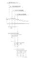
要部構成を抽出したものを図1に示す。レーザ発光装置31から出射されたレーザ光がポリゴンモータ部35によって反射され光学レンズを通過してドラム13に潜像が作られる。この時の走査線の開始場所を特定するのに所謂BD検出装置32が設置されている。図では省略されている電子写真プロセス機能部によってトナー画像が形成され、駆動ローラ30によって矢印方向に回転駆動される中間転写ベルト8上に転写される。
【0040】
この時作像される走査線の状態を図2(a),(b),(c),(d)に比較して示す。
【0041】
図2(a)は理想的な状態を示し、一定の速度で回転しているポリゴンモータP.V.と一定の速度で駆動されている中間転写ベルト8の速度線図ITB.Vを示すと同時に中間転写ベルト8上に転写された走査線を書き込む時の一定の露光タイミングTbd0と一定の露光時間T0に対応した一定の線長L0および一定の副走査間隔X0で書きこまれている様子を示す。中間転写ベルトITB移動方向および走査線Scan方向を図中矢印で示す。
【0042】
これらの理想的な状態に対して、転写ベルトの厚さの変動が全周にわたり存在する場合、図2(b)のようになる。転写ベルト速度は一定のものとはならずベルト厚みに基づき変化する。この時、転写ベルト上に所定の露光間隔で書き込まれた複数の走査線はX1、X2・・・Xnの間隔で中間転写ベルト8上に転写されることになる。これは単色の場合を示しているが、これが複数の画像形成プロセスユニットを通過していく結果、それぞれの走査線間隔がバラバラのものとなり色ズレが生じる。
【0043】
このような状態に対して本発明を適用した場合を図2(c),(d)を用いて説明する。まずは(c)に示すように、ポリゴンモータ35の回転数即ち回転速度を、転写ベルト厚みに基づく速度変動に対して打ち消す方向で変動させる。つまりは、ポリゴンモータ35の速度を中間転写ベルト8の厚みが増してベルト速度が上がれば、その分回転数を増加させ、中間転写ベルト8の厚みが減りベルト速度が遅くなればその分回転数を下げることにより、中間転写ベルト8上の走査線ピッチは実質的に等間隔X0とすることができる。
【0044】
しかしながら、ポリゴンモータ35の回転数を変化させることは、副走査方向の変化とともに主走査方向へも変化を与えることとなる。(c)中で示すように回転数の増減により、BD時間Tbd0を一定としている場合、走査線の書き込み開始位置が走査線毎に異なる弊害が発生する。また、走査線を露光する時間が一定のままポリゴン回転数が変化する(加減速する)ことにより、走査線長さもL1、L2・・Lnのように変化してしまう。
【0045】
そこで(d)に示すように、主走査方向の露光時間に以下の変化を与えることにより、主副走査方向に等間隔であり等長である走査線を実現することができる。
【0046】
転写ベルトの厚さ分布に基づく情報を、BDの基本時間Tbd0に対して変調したBDタイミングTbd(f)を与える。つまり、ベルトの厚さが厚くなり、ベルト移動速度が上がった場合には、BD時間を短く、ベルトの厚さが薄くなり、ベルト移動速度が下がった場合には、BD時間を長くとることにより、走査線の書き出し部の変動を防ぐことができる。
【0047】
また、転写ベルトの厚さ分布に基づく情報を、走査線を形成する露光タイミングT0に対して変調してT(f)とする。るつまり、ベルトの厚さが厚くなり、ベルト移動速度が上がった場合には、本来の露光タイミングより短く、ベルトの厚さが薄くなり、ベルト移動速度が下がった場合には、本来の露光タイミングより長くなるようにすることにより、走査線長L0の変動を防ぐことができる。
【0048】
また、ベルト体全周にわたる厚さ分布に対する厚さムラ補正を実施するときに、ベルト体に所謂ホームポジションを付加し、ベルト体の周回毎に繰り返される厚さ補正を所謂ホームポジション信号を利用して実施することにより、ベルト周期に適合した厚さムラ補正が可能である。
【0049】
ベルト体厚さ情報は、例えば特開平10−186787号公報に示されているような、ベルト体上に副走査方向に等間隔時間でマークを書き込んだ後にそれを読み出し、マークの時間間隔のズレ分を用いてベルト全体の厚さ分布を求める方法で入手しても良い。
【0050】
また、ベルト体厚さ情報が無くても、ベルト体の表面速度を別途用意した例えばレーザドップラー速度計を用いて測定し、その速度に適したポリゴンモータ速度制御および露光時間制御してもよい。
【0051】
また、ベルト体厚さ情報が無くても、ベルト体の表面までの駆動半径を別途用意した例えば変位計を用いて測定し、その変位に適したポリゴンモータ速度制御および露光時間制御してもよい。
【0052】
以上説明してきたベルト体はいわゆる電子写真方式における中間転写ベルトを用いたカラー画像形成装置ならびに搬送、転写ベルト方式によるカラー画像形成装置、感光体ベルト方式におけるカラー画像形成装置において、各色で形成されるトナー画像を一定のプロセス速度下で実行することが可能となるので、各色相互位置ズレをなくすことが可能であるとともに、複数のトナー画像間においても位置ズレをなくすことが可能となり、高品位な画像を得ることができる。
【0053】
【発明の効果】
以上説明したように,本発明によればベルト体の厚さが異なることに起因するベルト体移動速度の変動を、ベルトに設けられた基準マークを基準として別途計測されたベルト厚さプロファイルもしくはリアルタイムに計測されたベルト体移動速度を元に、ベルト体速度変動による位置ズレ量を打ち消すように、回転する回転多面鏡の回転数を変化させるとともに露光タイミングを変更することにより,単一の転写材内での画像転写位置精度を向上させるとともに、複数の画像間の画像転写位置の再現性に対しても位置精度を向上させることが可能となる。
【図面の簡単な説明】
【図1】本発明の実施例を説明する図
【図2】(a)(b)(c)(d) 本発明の実施例を説明する図
【図3】従来例における画像形成装置の構成を説明する図
【図4】従来における理想的な画像形成を説明する図
【図5】従来における画像形成時の問題を説明する図
【図6】従来における画像形成時の問題を説明(ベルト厚さによる累積位置ズレ)する図
【図7】従来におけるな画像形成時の問題を説明(画像内色ズレ)する図
【符号の説明】
1 カセット
2 給紙ローラ
3、4、5、6 搬送ローラ
7 レジストローラ
8 中間転写ベルト
9 二次転写部
10 電子写真プロセスユニット(画像形成部)
12 画像読み込み装置
13 感光体(感光ドラム)
14 帯電器
15 露光装置
16 現像器
17 転写器
18 クリーニング装置
19 定着器(定着ローラ対)
20 反転部
30 駆動ローラ
31 レーザ発光装置
32 BD検出装置
35 ポリゴンモータ部(ポリゴンモータ)[0001]
TECHNICAL FIELD OF THE INVENTION
The present invention relates to an electrophotographic image forming apparatus that develops a latent image formed on a photoreceptor with toner, and transfers and fixes the toner on a transfer material to perform recording.
[0002]
In particular, it is used in an image recording apparatus having functions such as a copying machine and a printer, and in an image forming apparatus used as an output device such as a multifunction machine and a work station which also have such functions.
[0003]
[Prior art]
A plurality of electrophotographic process units in which a charging device and a developing device are arranged around a photoreceptor are juxtaposed in the device, and an optical image is formed on the photoreceptor surface in each process unit by an exposure device using a laser, LED light, or the like. A latent image is formed on the surface of the photoreceptor by visualizing the latent image, the latent image is visualized using a toner by a developing device, and then the toner is sequentially transferred to an intermediate transfer belt. In recent years, an image forming apparatus for forming an image has been put to practical use.
[0004]
FIG. 3 shows an example of a conventional color printing apparatus. This apparatus is a color electrophotographic copying machine that forms an image by superimposing toners of four colors of magenta, cyan, yellow, and black.
[0005]
[0006]
In each of the
[0007]
A toner image corresponding to each color is formed on each of the
[0008]
After the transfer material stored in the
The transfer material sent out from the registration roller 7 joins with the
[0009]
The transfer material on which the transfer of the four-color toner images has been completed reaches the
[0010]
The transfer material on which the toner image has been fixed on the surface by the
[0011]
[Problems to be solved by the invention]
However, in the conventional example, the following two problems were significant when driving the belt member.
[0012]
Due to the belt driving roller and the problem such as geometrical shape deviation between the driving roller and the driven roller, the belt body speed changes successively. Therefore, in an image sequentially formed on the belt body, the belt body moving direction, so-called, There has been a problem with image quality such that a position shift occurs between the respective color images in the sub-scanning direction on the transfer material, and the color shift of an image formed on the transfer material deteriorates.
[0013]
These main factors are considered as follows.
[0014]
(1) The driving speed of the driving roller having a radius r driven at a constant angular speed ω and the belt speed V defined by the belt thickness h are represented as follows.
[0015]
V = (r + h / 2) · ω (1)
When the eccentricity Δr is superimposed on the driving roller, the fluctuation ΔV of the belt body moving speed V defined by the driving roller is expressed as follows.
[0016]
ΔV ω = Δr ω · ω ( 2)
ω: angular velocity (driving roller rotation cycle)
The speed variation [Delta] V omega of the drive roller cycle, the respective color images produces a positional displacement of the drive roller cycle.
[0017]
{Circle around (2)} Changes in the belt moving speed defined by the belt driving roller also occur due to fluctuations in the thickness direction over the entire circumference of the belt, and as a result, each color on the transfer material collectively transferred from the belt is changed. As the image quality is degraded such that the image deviates from the ideal position, the image varies between a plurality of transfer materials, and the reproducibility of the repetitive position between the transfer materials is deteriorated.
[0018]
This is because if the belt thickness h wound on a drive roller having a radius r driven at a constant angular velocity ω has a thickness variation Δh over the entire circumferential length, the belt body moving speed defined by the drive roller The variation ΔV L of V is expressed as follows.
[0019]
ΔV L = Δh L · ω (3)
L: Belt full-peripheral period diagram schematically showing the relationship between the belt linear velocity fluctuation defined by the belt driving roller and the positional deviation relationship of the image formed by the belt ideal case and the case including the above problem. 4, as shown in FIG.
[0020]
In addition to showing the exposure timing by each exposure device, the horizontal axis represents the time t on the moving speed of the belt body, the vertical axis represents the belt line moving speed v, and the color scanning lines formed on the belt body are moved in the main scanning direction. This is shown in parallel, and shows how data is written in chronological order.
[0021]
In an ideal case, the transfer belt speed moves at a constant speed V as shown in FIG. A case is shown in which a transfer time difference corresponding to the installation interval of the image forming apparatus for each color of YMCK is given on the transfer belt moving at a constant speed, and writing is given one by one in the main scanning direction at equal intervals in the sub-scanning direction. As a result, it can be seen that the scanning lines of each of the YMCK colors are written at regular intervals in the sub-scanning direction without deviation.
[0022]
On the other hand, FIG. 5 shows a case where the speed of the belt body changes due to the belt thickness and the drive roller eccentricity. The fine AC component fluctuation in the belt speed fluctuation indicated by the solid line corresponds to the above-mentioned (1) the drive roller eccentricity period, and the large undulation component indicated by the broken line corresponds to the (2) belt speed unevenness period. Have fluctuations.
[0023]
In this case, even if the scanning lines are formed by the respective color image forming apparatuses at equal intervals in the sub-scanning direction, the sub-scanning intervals of the scanning lines become uneven by the speed variation of the belt body, and the state occurs for each color. A color shift between the YMCK colors occurs.
[0024]
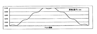
The results of trial calculations as specific quantities are shown. When an intermediate transfer belt having a total length of 2000 mm has a thickness unevenness with an amplitude of about 5 μm, an eccentricity of the drive roller diameter is set to 10 μm, and a process speed is set to about 400 mm / s, the accumulation of images on the belt when the belt rotates around the belt. The displacement is at most about 100 μm. The result is shown in FIG. FIG. 7 shows an example of the accumulated positional deviation amount of each color and the color deviation amount generated between the respective colors when the image formation of each color is performed in a state where the accumulated positional deviation is present. Even when an image is formed using a belt having an amplitude of only about 5 μm, the maximum color shift amount on the paper is close to 100 μm. This amount is the ideal case for everything else, and in fact various factors are added to it, so if high quality image quality is required, a single element of 100 μm unit Is no longer acceptable.
[0025]
Accordingly, an object of the present invention is to solve the above problem (2) and to provide an image forming apparatus capable of achieving improvement in image quality. (Problem (1) can solve the color misregistration problem between images, for example, by making the transfer distance of each color image and the outer circumference of the belt drive roller equal or an integer ratio).
[0026]
Means and Action for Solving the Problems
SUMMARY OF THE INVENTION In order to solve the above-mentioned problems, the present invention provides a color image forming apparatus with less color shift by providing the following configurations (1) to (10).
[0027]
(1) An image is formed on a main body using one or more exposure devices and one or more parallel electrophotographic process units and a belt body, and a toner image is transferred onto a transfer material. In an image forming apparatus that performs a process of fixing a toner image to a transfer material by applying a desired amount of heat and pressure to the transfer material using
A belt body and one drive roller for driving the belt;
At least one driven roller including means for stretching the belt body,
A criterion defining the start of the thickness profile of the stretched belt body,
An image forming apparatus, wherein a scanning speed and an exposure timing of an exposure device are changed so as to cancel an image shift caused by a speed variation caused by a thickness profile of the belt.
[0028]
(2) The image forming apparatus according to (1), wherein the exposure device is a rotary polygon mirror.
[0029]
(3) The image forming apparatus according to (1), wherein the number of rotations of the exposure device is changed so as to cancel a position shift in the sub-scanning direction due to a variation in thickness of the belt member.
[0030]
(4) In response to changing the rotation speed of the exposure device so as to cancel the displacement in the sub-scanning direction due to the thickness variation of the belt member, the main scanning synchronization reference signal of the exposure device is displaced in the main scanning direction. The image forming apparatus according to (3), wherein the image forming apparatus is changed so as to cancel out.
[0031]
(5) The exposure timing of the exposure device in the main scanning direction is modulated to change the main scanning magnification in response to the rotation speed of the exposure device being changed so as to cancel the positional deviation in the sub-scanning direction due to the thickness variation of the belt member. The image forming apparatus according to the above (3), wherein the correction has been performed.
[0032]
(6) The image forming apparatus according to (1), wherein the belt body is an intermediate transfer belt.
[0033]
(7) The image forming apparatus according to (1), wherein the belt body is a transfer / transport belt.
[0034]
(8) The image forming apparatus according to (1), wherein the belt body is a photosensitive belt.
[0035]
(9) The image according to (1), wherein the thickness profile of the belt is measured using a displacement measuring device installed in an image forming apparatus, and is fed back as information for controlling the rotation speed of the exposure device. Forming equipment.
[0036]
(10) The image forming apparatus according to (1), wherein the speed profile of the belt is measured by using a speed measuring device installed in the image forming apparatus, and is fed back as information for controlling the rotation speed of the exposure device. apparatus.
[0037]
BEST MODE FOR CARRYING OUT THE INVENTION
Hereinafter, embodiments of the present invention will be described based on examples with reference to the drawings.
[0038]
[Example 1]
The overall configuration of the apparatus is the same as that of the conventional example, and a description thereof will be omitted.
[0039]
FIG. 1 shows an extracted main part configuration. The laser light emitted from the laser
[0040]
The states of the scanning lines formed at this time are shown in comparison with FIGS. 2 (a), (b), (c) and (d).
[0041]
FIG. 2A shows an ideal state, in which the polygon motor P.R. V. And a speed diagram ITB. Of the
[0042]
FIG. 2B shows a case where the transfer belt thickness varies over the entire circumference with respect to these ideal states. The transfer belt speed is not constant but changes based on the belt thickness. At this time, a plurality of scanning lines written on the transfer belt at predetermined exposure intervals are transferred onto the
[0043]
The case where the present invention is applied to such a state will be described with reference to FIGS. First, as shown in (c), the rotation speed, that is, the rotation speed of the
[0044]
However, changing the number of revolutions of the
[0045]
Thus, as shown in (d), by giving the following changes to the exposure time in the main scanning direction, it is possible to realize scanning lines having equal intervals and equal lengths in the main and sub scanning directions.
[0046]
A BD timing Tbd (f) obtained by modulating information based on the transfer belt thickness distribution with respect to the BD basic time Tbd0 is given. That is, when the belt thickness is increased and the belt moving speed is increased, the BD time is shortened. When the belt thickness is decreased and the belt moving speed is decreased, the BD time is increased. In addition, it is possible to prevent the variation of the writing portion of the scanning line.
[0047]
Further, information based on the thickness distribution of the transfer belt is modulated with respect to an exposure timing T0 for forming a scanning line to be T (f). In other words, when the belt thickness increases and the belt moving speed increases, the original exposure timing is shorter than the original exposure timing. When the belt thickness decreases and the belt moving speed decreases, the original exposure timing decreases. By making the length longer, it is possible to prevent the fluctuation of the scanning line length L0.
[0048]
Further, when performing thickness unevenness correction for the thickness distribution over the entire circumference of the belt body, a so-called home position is added to the belt body, and the thickness correction that is repeated for each rotation of the belt body is performed using a so-called home position signal. By doing so, thickness unevenness correction suitable for the belt cycle can be performed.
[0049]
The belt body thickness information is obtained by writing marks on the belt body at equal intervals in the sub-scanning direction as described in, for example, Japanese Patent Laid-Open No. It may be obtained by a method of obtaining the thickness distribution of the entire belt using the minutes.
[0050]
Even if there is no belt body thickness information, the surface speed of the belt body may be measured using a separately prepared laser Doppler velocimeter, for example, and polygon motor speed control and exposure time control suitable for the speed may be performed.
[0051]
Further, even if there is no belt body thickness information, the drive radius up to the surface of the belt body may be measured using, for example, a displacement meter separately prepared, and polygon motor speed control and exposure time control suitable for the displacement may be performed. .
[0052]
The belt member described above is formed in each color in a color image forming apparatus using an intermediate transfer belt in a so-called electrophotographic system, a color image forming apparatus using a transfer belt system, and a color image forming apparatus using a photosensitive belt system. Since it is possible to execute the toner image at a constant process speed, it is possible to eliminate the positional deviation between the respective colors, and it is also possible to eliminate the positional deviation between a plurality of toner images. Images can be obtained.
[0053]
【The invention's effect】
As described above, according to the present invention, the fluctuation of the belt body moving speed due to the difference in the thickness of the belt body is measured by using a belt thickness profile separately measured with reference to a reference mark provided on the belt or a real-time profile. By changing the number of rotations of the rotating polygon mirror and changing the exposure timing to cancel the amount of displacement due to the fluctuation of the belt speed, based on the measured speed of the belt speed It is possible to improve the accuracy of the image transfer position within the image and the accuracy of the reproducibility of the image transfer position between a plurality of images.
[Brief description of the drawings]
FIG. 1 is a diagram illustrating an embodiment of the present invention. FIG. 2 is a diagram illustrating an embodiment of the present invention. FIG. 3 is a configuration of an image forming apparatus in a conventional example. FIG. 4 illustrates a conventional ideal image formation. FIG. 5 illustrates a conventional image forming problem. FIG. 6 illustrates a conventional image forming problem (belt thickness). FIG. 7 is a diagram for explaining a problem in conventional image formation (color shift in an image).
DESCRIPTION OF
12
14
Claims (10)
ベルト体とベルトを駆動するための1つの駆動ローラと、
該ベルト体を張架する手段を含む少なくとも1つの従動ローラとを有し、
張架されたベルト体の厚さプロファイルの開始を規定する基準を有し、
該ベルトの厚さプロファイルによって生じる速度変動による画像ズレを打ち消すように露光装置の走査速度、露光タイミングを変更したことを特徴とする画像形成装置。An image is formed on the main body using one or more exposure devices and one or more parallel electrophotographic process units and a belt body, and after transferring a toner image onto a transfer material, the desired image is formed using a fixing device. An image forming apparatus that performs a process of fixing a toner image to a transfer material by applying heat and pressure of the transfer material to the transfer material,
A belt body and one drive roller for driving the belt;
At least one driven roller including means for stretching the belt body,
A criterion defining the start of the thickness profile of the stretched belt body,
An image forming apparatus, wherein a scanning speed and an exposure timing of an exposure device are changed so as to cancel an image shift caused by a speed variation caused by a thickness profile of the belt.
Priority Applications (1)
| Application Number | Priority Date | Filing Date | Title |
|---|---|---|---|
| JP2002265559A JP2004102039A (en) | 2002-09-11 | 2002-09-11 | Image forming device |
Applications Claiming Priority (1)
| Application Number | Priority Date | Filing Date | Title |
|---|---|---|---|
| JP2002265559A JP2004102039A (en) | 2002-09-11 | 2002-09-11 | Image forming device |
Publications (1)
| Publication Number | Publication Date |
|---|---|
| JP2004102039A true JP2004102039A (en) | 2004-04-02 |
Family
ID=32264670
Family Applications (1)
| Application Number | Title | Priority Date | Filing Date |
|---|---|---|---|
| JP2002265559A Withdrawn JP2004102039A (en) | 2002-09-11 | 2002-09-11 | Image forming device |
Country Status (1)
| Country | Link |
|---|---|
| JP (1) | JP2004102039A (en) |
Cited By (3)
| Publication number | Priority date | Publication date | Assignee | Title |
|---|---|---|---|---|
| JP2006313251A (en) * | 2005-05-09 | 2006-11-16 | Ricoh Co Ltd | Image forming apparatus, image forming method, program to make computer perform the image forming method and recording medium |
| JP2009036993A (en) * | 2007-08-01 | 2009-02-19 | Ricoh Co Ltd | Image forming apparatus |
| US8619318B2 (en) | 2007-07-06 | 2013-12-31 | Canon Kabushiki Kaisha | Image forming apparatus with image scaling ratio setting feature |
-
2002
- 2002-09-11 JP JP2002265559A patent/JP2004102039A/en not_active Withdrawn
Cited By (3)
| Publication number | Priority date | Publication date | Assignee | Title |
|---|---|---|---|---|
| JP2006313251A (en) * | 2005-05-09 | 2006-11-16 | Ricoh Co Ltd | Image forming apparatus, image forming method, program to make computer perform the image forming method and recording medium |
| US8619318B2 (en) | 2007-07-06 | 2013-12-31 | Canon Kabushiki Kaisha | Image forming apparatus with image scaling ratio setting feature |
| JP2009036993A (en) * | 2007-08-01 | 2009-02-19 | Ricoh Co Ltd | Image forming apparatus |
Similar Documents
| Publication | Publication Date | Title |
|---|---|---|
| EP2060953B1 (en) | Colour image forming apparatus with registration correction | |
| JP4865283B2 (en) | Image forming apparatus and phase alignment method for a plurality of image carriers | |
| EP1031887A2 (en) | Image forming apparatus and program | |
| JP2000098675A (en) | Image forming device | |
| JP2006084812A (en) | Image carrier speed fluctuation phase difference detection method and image forming apparatus using the method | |
| JP2000199988A (en) | Image forming device | |
| JP6447137B2 (en) | Image forming apparatus | |
| JP2006201270A (en) | Image forming device | |
| JP2004102039A (en) | Image forming device | |
| JP2001109353A (en) | Image forming device | |
| JPH0736249A (en) | Color image forming device | |
| JP2004078101A (en) | Color image forming apparatus | |
| JP2001147573A (en) | Device and method for forming image | |
| JP2002311672A (en) | Image forming device | |
| JP3548164B2 (en) | Image forming device | |
| JPH04340563A (en) | Color image forming device | |
| JP2007333759A (en) | Image forming apparatus | |
| JPH08137153A (en) | Image forming device | |
| JP2003270896A5 (en) | ||
| JP3496540B2 (en) | Color image forming apparatus and registration pattern forming method | |
| JPH11174869A (en) | Image forming device | |
| JPS6311965A (en) | Image forming device | |
| JP2003233236A (en) | Image forming apparatus | |
| JP2010049027A (en) | Image forming apparatus | |
| JP5258184B2 (en) | Image forming apparatus |
Legal Events
| Date | Code | Title | Description |
|---|---|---|---|
| A300 | Withdrawal of application because of no request for examination |
Free format text: JAPANESE INTERMEDIATE CODE: A300 Effective date: 20060110 |