JP2004100557A - Fuel injection control device of internal combustion engine - Google Patents
Fuel injection control device of internal combustion engine Download PDFInfo
- Publication number
- JP2004100557A JP2004100557A JP2002263009A JP2002263009A JP2004100557A JP 2004100557 A JP2004100557 A JP 2004100557A JP 2002263009 A JP2002263009 A JP 2002263009A JP 2002263009 A JP2002263009 A JP 2002263009A JP 2004100557 A JP2004100557 A JP 2004100557A
- Authority
- JP
- Japan
- Prior art keywords
- injection
- fuel injection
- fuel
- change rate
- pressure
- Prior art date
- Legal status (The legal status is an assumption and is not a legal conclusion. Google has not performed a legal analysis and makes no representation as to the accuracy of the status listed.)
- Pending
Links
Images


Classifications
-
- Y—GENERAL TAGGING OF NEW TECHNOLOGICAL DEVELOPMENTS; GENERAL TAGGING OF CROSS-SECTIONAL TECHNOLOGIES SPANNING OVER SEVERAL SECTIONS OF THE IPC; TECHNICAL SUBJECTS COVERED BY FORMER USPC CROSS-REFERENCE ART COLLECTIONS [XRACs] AND DIGESTS
- Y02—TECHNOLOGIES OR APPLICATIONS FOR MITIGATION OR ADAPTATION AGAINST CLIMATE CHANGE
- Y02T—CLIMATE CHANGE MITIGATION TECHNOLOGIES RELATED TO TRANSPORTATION
- Y02T10/00—Road transport of goods or passengers
- Y02T10/10—Internal combustion engine [ICE] based vehicles
- Y02T10/40—Engine management systems
Abstract
Description
【0001】
【発明の属する技術分野】
本発明は、内燃機関の燃料噴射制御装置に関し、詳細にはディーゼル機関の燃焼を最適化する燃料噴射制御装置に関する。
【0002】
【従来の技術】
近年の排気ガス規制の強化や騒音低減に対する要求から、ディーゼル機関においても燃焼室内での燃焼最適化の要求が高まってきている。燃焼最適化のためにはディーゼル機関においても燃料噴射量、燃料噴射時期、噴射期間などを正確に制御することが必要となる。
【0003】
しかし、ディーゼル機関では、理論空燃比よりかなり高いリーン空燃比領域で燃焼が行われており、ガソリン機関のように、正確に空燃比を目標空燃比に維持する必要がなかったため、従来、燃料噴射量、燃料噴射時期などの燃料噴射パラメータもガソリン機関ほどには精密な制御は行われていない。又、従来、ディーゼル機関では機関運転条件(回転数、アクセル開度など)から燃料噴射量、噴射時期、噴射圧、EGRガス量などの目標値を決定し、この目標値に応じて燃料噴射弁などをオープンループ制御しているが、オープンループ制御では、実際の燃料噴射量が目標噴射量に対して誤差を生じることを防止できず、燃焼状態を目標とする状態に正確に制御することは困難であった。
【0004】
更に、排気ガス性状の改善と騒音の低減のためには、各気筒の1サイクル中に、主燃料噴射の前後に複数回の燃料噴射を行い、燃焼状態を最適に調整するマルチ燃料噴射が有効である。しかし、マルチ燃料噴射を行うためには、複数回の燃料噴射のそれぞれの燃料噴射量と噴射時期とを精密に制御する必要がある。
【0005】
また、燃焼状態改善のために最近ディーゼル機関において採用されるようになったコモンレール式高圧燃料噴射装置では、燃料噴射時間が短く、しかも噴射中に燃料噴射圧力が変化する等のため、燃料噴射量に誤差を生じやすい問題がある。このため、コモンレール式高圧燃料噴射装置では燃料噴射弁の公差を小さく設定して燃料噴射精度を向上させる等の対策が取られているが、実際には燃料噴射弁は各部の摩耗などにより使用期間ともに燃料噴射特性が変化するため、燃料噴射量を常に正確に目標値に一致させることは困難である。
【0006】
このように、ディーゼル機関では燃料噴射量などに誤差が生じやすいため最適な燃焼状態を得る目標値を設定できても、実際にその燃料噴射量を目標値に合致させることが困難な事情がある。
燃焼状態を目標とする燃焼状態に合致させるためには、実際の燃焼状態を何らかの形で検出し、実際の燃焼状態が目標とする燃焼状態に合致するように燃料噴射量や燃料噴射時期などの燃料噴射パラメータをフィードバック制御することが有効である。
【0007】
このように、燃焼状態を検出して燃料噴射パラメータをフィードバック制御する内燃機関の燃焼制御装置の例としては、特許文献1に記載されたものがある。
【0008】
特許文献1の装置は、ディーゼル機関の燃焼騒音を計測し、計測した燃焼騒音に基づいてパイロット噴射量が多すぎるのか少なすぎるのかを判断し、これに基づいてパイロット噴射量を補正するものである。また、燃焼騒音としては、燃焼室内圧力を検出する筒内圧センサで検出した筒内圧の微分値または2階微分値を用いることによりメカニカルな振動の影響を除いて燃焼騒音の検出精度を向上させるようにしている。
【0009】
すなわち、特許文献1の装置は実際に計測した燃焼騒音に基づいてパイロット噴射量をフィードバック制御することにより、燃焼騒音を常に目標レベル以下に抑制するものである。
【0010】
【特許文献1】
特開2001−123871号公報
【0011】
【発明が解決しようとする課題】
上記特許文献1の装置では、実際に計測した燃焼騒音に基づいてパイロット噴射量をフィードバック制御するため、燃焼騒音を常に目標レベル以下に抑制することができる。しかし、特許文献1の装置では、燃焼騒音は目標値以下に抑制されるものの、必ずしも常に良好な燃焼状態が得られるとは限らず、排気性状が悪化する場合も生じる。
【0012】
すなわち、良好な排気性状を得るためには、パイロット噴射の噴射量のみではなく噴射時期をも適切に制御する必要があるが、特許文献1の装置では、燃焼騒音に基づいてパイロット噴射の噴射量のみを制御しているため、燃焼騒音は低下したとしても、排気性状が常に向上するとは限らない問題がある。
【0013】
また、特許文献1の装置は、パイロット噴射、それもパイロット噴射を1回だけ行う運転のみを対象としているため、複数回のパイロット噴射や、主燃料噴射の後にアフター噴射を行う場合があるマルチ燃料噴射において、各燃料噴射の噴射量や噴射時期を適切に制御することはできない。
【0014】
本発明は、上記従来技術の問題に鑑み、複数回の燃料噴射を行う場合にも各燃料噴射の噴射量と噴射時期とを適正な値に制御することが可能な内燃機関の燃料噴射制御装置を提供することを目的としている。
【0015】
【課題を解決するための手段】
請求項1に記載の発明によれば、主燃料噴射に加えて、主燃料噴射の前または後、もしくは前と後との両方に機関燃焼室に燃料を噴射するマルチ燃料噴射を行う内燃機関の燃料噴射制御装置であって、機関燃焼室内の圧力を検出する筒内圧センサを備え、前記筒内圧センサで検出した燃焼室内圧力のクランク角または時間に対する一次変化率と二次変化率とを算出し、前記算出した一時変化率に基づいて前記マルチ燃料噴射におけるそれぞれの燃料噴射の噴射量が適切な値か否かを判定し、前記算出した二次変化率に基づいて燃焼室内の燃焼開始時期が適切か否かを判定するとともに、前記判定結果に応じて前記マルチ燃料噴射の各燃料噴射の噴射量と噴射時期とを制御する、内燃機関の燃料噴射制御装置が提供される。
【0016】
すなわち、請求項1の発明では筒内圧センサで検出した燃焼室内圧力Pの変化率(クランク角θに対する変化率(dP/dθ)と(d2P/dθ2)、または時間tに対する変化率(dP/dt)と(d2P/dt2))に基づいてマルチ燃料噴射における各燃料噴射の噴射量と噴射時期とが制御される。以下、クランク角に対する変化率の場合について説明するが、時間に対する変化率を用いた場合も以下の説明と同様である。
【0017】
燃焼室内に噴射された燃料が燃焼すると燃焼室内の圧力は上昇する。このため、燃焼室内圧力変化率(dP/dθ)の値は、マルチ燃料噴射の各燃料噴射が行われる毎に増大し、各噴射に対応した数だけ(dP/dθ)のピークが生じる。
また、このピークの大きさは燃料噴射量と相関があることが判っている。
【0018】
マルチ燃料噴射が行われる場合には、1行程サイクルに対して複数回の燃料噴射が行われるが、各燃料噴射により噴射された燃料が燃焼すると燃焼圧が上昇するため、燃焼圧そのものにも各燃料噴射により噴射された燃料の燃焼に対応するピークが生じているはずである。しかし、実際には、特にマルチ燃料噴射で各燃料噴射の間隔が短いような場合には燃焼室内の圧力上昇は各噴射によるものが相互に干渉しあってしまい、各燃料噴射に対応する圧力ピークを分離検出することは困難である。
【0019】
これに対して、圧力変化率(dP/dθ)はそれぞれの燃料噴射に対して明瞭なピーク値が現れる。このため、(dP/dθ)を用いて、マルチ燃料噴射が行われる場合も各噴射の噴射量を個別に判断することが可能となるため、噴射量の正確なフィードバック制御を行うことができる。
【0020】
また、燃焼室内圧力の二次変化率(d2P/dθ2)も上記一次変化率と同様に各燃料噴射毎に存在する。また、燃焼室内圧力の二次変化率は燃焼開始時の圧力が上昇を開始し始めた時期に対応したピークを有するため、燃焼室内圧力そのもの、或いは圧力変化率(dP/dθ)では判別が困難な各燃料噴射に対応する燃焼開始時期も明確に判別することができる。このため、マルチ燃料噴射が行われる場合も圧力の二次変化率(d2P/dθ2)を用いて各噴射に対応する燃焼開始時期を個別に判断することが可能となるため、噴射時期の正確なフィードバック制御を行うことができる。
【0021】
請求項2に記載の発明によれば、前記二次変化率が予め定めた基準値を越えた時点を各燃料噴射で噴射された燃料の燃焼開始時期と判断し、該燃焼開始時期が機関運転条件に応じて予め定めた時期に一致するように前記マルチ燃料噴射の各燃料噴射の噴射量と噴射時期とを制御する、請求項1に記載の内燃機関の燃料噴射制御装置が提供される。
【0022】
すなわち、請求項2の発明では、燃焼室内の圧力の二次変化率が所定の基準値を越えた時を燃焼室内の燃焼開始時期と判断する。圧力の二次変化率のピークは燃焼開始時期に対応しているが、本発明では、極大値を検出する代わりに二次変化率が増大して基準値以上になった時点を燃焼開始時期と判断し、この検出した燃焼開始時期が予め実験等により求めておいた最適な燃焼時期に一致するように各燃料噴射の噴射時期をフィードバック制御する。このように、圧力二次変化率が基準値以上になったか否かを判断することにより、二次変化率のピーク検出(極大値検出)を行う必要がなくなるため、簡易に燃焼開始時期が判定できるため、制御装置の計算負荷を軽減することができる。
【0023】
請求項3に記載の発明によれば、前記算出した一次変化率の前記マルチ燃料噴射における各燃料噴射に対応する値の全部が、それぞれ所定の基準範囲になるように各燃料噴射における噴射量を制御する請求項1に記載の内燃機関の燃料噴射制御装置が提供される。
【0024】
すなわち、請求項3ではマルチ燃料噴射の各噴射に対応する燃焼室内圧力の一次変化率の値の全部がそれぞれの基準範囲になるように各燃料噴射の噴射量が制御される。前述したように、各燃料噴射に対応する圧力の一次変化率と各燃料噴射における噴射量とは相関があるが、各燃料噴射に対応する圧力の一次変化率のみでは対応する燃料噴射の噴射量が適切か否かが必ずしも定まらない場合がある。例えば、仮にパイロット噴射に対応する圧力二次変化率が基準値をこえていたとしても、パイロット噴射の量が少ない場合には主燃料噴射の燃料の燃焼による圧力上昇速度が大きくなり、圧力の一次変化率のピーク値が過大になる。このため、パイロット噴射の噴射量を適正にするためにはパイロット噴射の噴射量を、主燃料噴射に対応する圧力の一次変化率が或る上限値以下になるまで減少させる必要がある。
【0025】
本発明では、全部の燃料噴射の噴射量が適切になる時の、各燃料噴射に対応する圧力の一次変化率の基準範囲が予め実験などにより定めてあり、機関運転中に各燃料噴射に対応する圧力の一次変化率がこの基準範囲に入るように各燃料噴射の噴射量を制御する。これにより、全部の燃料噴射の燃料噴射量が適切な値に制御されるようになる。
【0026】
【発明の実施の形態】
以下、添付図面を用いて本発明の実施形態について説明する。
図1は、本発明の燃料噴射装置を自動車用ディーゼル機関に適用した場合の実施形態の概略構成を示す図である。
【0027】
図1において、1は内燃機関(本実施形態では#1から#4の4つの気筒を備えた4気筒4サイクルディーゼル機関が使用される)、10aから10dは機関1の#1から#4の各気筒燃焼室に直接燃料を噴射する燃料噴射弁を示している。燃料噴射弁10aから10dは、それぞれ燃料通路(高圧燃料配管)を介して共通の蓄圧室(コモンレール)3に接続されている。コモンレール3は、高圧燃料噴射ポンプ5から供給される加圧燃料を貯留し、貯留した高圧燃料を高圧燃料配管を介して各燃料噴射弁10aから10dに分配する機能を有する。
【0028】
図1に20で示すのは、機関の制御を行う電子制御ユニット(ECU)である。ECU20は、リードオンリメモリ(ROM)、ランダムアクセスメモリ(RAM)、マイクロプロセッサ(CPU)、入出力ポートを双方向バスで接続した公知の構成のマイクロコンピュータとして構成されている。ECU20は、本実施形態では、燃料ポンプ5の吐出量を制御してコモンレール3圧力を機関運転条件に応じて定まる目標値に制御する燃料圧制御を行っている他、機関運転状態に応じて燃料噴射の噴射時期及び噴射量を設定するとともに、後述する筒内圧センサ出力に基づいて求めた燃焼室内圧の一次変化率と二次変化率とを用いて燃料噴射量、噴射時期等をフィードバック制御する燃料噴射制御等の機関の基本制御を行う。
【0029】
これらの制御を行なうために、本実施形態ではコモンレール3にはコモンレール内燃料圧力を検出する燃料圧センサ27が設けられている他、機関1のアクセルペダル(図示せず)近傍にはアクセル開度(運転者のアクセルペダル踏み込み量)を検出するアクセル開度センサ21が設けられている。また、図1に23で示すのは機関1のカム軸の回転位相を検出するカム角センサ、25で示すのはクランク軸の回転位相を検出するクランク角センサである。カム角センサ23は、機関1のカム軸近傍に配置され、クランク回転角度に換算して720度毎に基準パルスを出力する。また、クランク角センサ25は、機関1のクランク軸近傍に配置され所定クランク回転角毎(例えば15度毎)にクランク角パルスを発生する。
【0030】
ECU20は、クランク角センサ25から入力するクランク回転角パルス信号の周波数から機関回転数を算出し、アクセル開度センサ21から入力するアクセル開度信号と、機関回転数とに基づいて燃料噴射弁10aから10dの燃料噴射時期と燃料噴射量とを算出する。
【0031】
また、図1に29aから29dで示すのは、各気筒10aから10dに配置され、気筒燃焼室内の圧力を検出する公知の形式の筒内圧センサである。筒内圧センサ29aから29dで検出された各燃焼室内圧力は、ADコンバータ30を経てECU20に供給される。
【0032】
本実施形態では、コモンレール3の燃料圧力はECU20により機関運転状態に応じた圧力に制御され、例えば10MPaから150MPa程度の高圧で、しかも広い範囲で変化する。また、本実施形態では、機関1は各気筒の行程1サイクルの間に複数回気筒内に燃料を噴射するマルチ燃料噴射を行う。
【0033】
図2は、本実施形態におけるマルチ燃料噴射を構成するそれぞれの燃料噴射を説明する図である。
【0034】
図2において、横軸はクランク角(CA)を示し、横軸状のTDCは圧縮上死点を表している。また、図2の縦軸はそれぞれの燃料噴射の噴射率を表しており、それぞれの山の面積は概略各燃料噴射の相対的な燃料噴射量を示している。図に示すように、マルチ燃料噴射では早期パイロット噴射、近接パイロット噴射、メイン噴射(主燃料噴射)、アフター噴射、ポスト噴射等の全部または一部が行われる。
【0035】
以下、メイン噴射以外のそれぞれの燃料噴射について簡単に説明する。
(1)早期パイロット噴射
早期パイロット噴射は、メイン噴射よりかなり早い時期(例えばメイン噴射開始よりクランク角で20度(20°CA)以上早い時期)に行われるパイロット噴射である。早期パイロット噴射で噴射された燃料は予混合気を形成し、圧縮着火するためNOXやパティキュレートをほとんど生成せず、早期パイロット噴射を行うことにより排気性状を向上させることができる。また、早期パイロット噴射は、燃焼室内の温度と圧力とを上昇させ、後述する近接パイロット噴射やメイン噴射の着火遅れ期間を短縮するため、メイン噴射による燃焼の騒音やNOX生成を抑制することができる。
【0036】
早期パイロット噴射は、比較的燃焼室内の温度圧力が低い時点で行われるため、噴射量が多い場合には噴射された燃料が液状のままシリンダ壁に到達して、潤滑油希釈などの問題を起こす。このため、早期パイロット噴射は噴射量が多い場合には必要とされる噴射量を複数回に分割して少量ずつ噴射することによりシリンダ壁への液状燃料の到達を防止する。
【0037】
(2)近接パイロット噴射
近接パイロット噴射は、メイン噴射の直前(例えば、メイン噴射開始より20°CA以内)に行われるパイロット噴射である。近接パイロット噴射は、早期パイロット噴射に較べて炭化水素の発生が少なく、早期パイロット噴射と同様にメイン噴射の着火遅れ期間を短縮してメイン噴射の騒音やNOX生成を抑制することができる。
【0038】
(3)アフター噴射
アフター噴射は、メイン噴射終了直後、または比較的短い間隔(例えばメイン噴射終了後15°CA以内)に開始される噴射である。
アフター噴射は、メイン噴射の燃料の燃焼後期に再度燃焼室内の温度、圧力、乱れなどを増加させて燃焼を良好にすることと、メイン噴射の噴射量を減らすことを目的として行われる。
【0039】
すなわち、メイン噴射の燃焼後期には燃焼室内の温度、圧力は低下し、筒内の乱れも小さくなっているため、燃料が燃焼しにくくなっている。この状態でアフター噴射を行うことにより、燃料の噴射による乱れの増大と噴射された燃料の燃焼による温度、圧力の増大が生じるため、燃焼室内の雰囲気が燃焼を促進する方向に改善される。また、アフター噴射の噴射量分だけメイン噴射の噴射量を減らすことができるため、メイン噴射燃料により生成される局所的な過濃領域の生成が抑制される。また、アフター噴射の量と時期とを適切に設定することによりメイン噴射量を低減して燃焼による筒内最高温度を低下させることができるため、NOXの生成が抑制される効果がある。
【0040】
(4)ポスト噴射
ポスト噴射は、メイン噴射終了後比較的間隔をあけて(例えばメイン噴射終了後15°CA以上)開始される燃料噴射である。ポスト噴射の主な目的は排気温度、圧力を上昇させることである。
【0041】
例えば、排気系に配置した排気浄化触媒の温度が低く活性化温度に到達しないため排ガス浄化作用を得られないような場合には、ポスト噴射を行うことにより排気温度を上昇させて短時間で触媒温度を活性化温度まで上昇させることができる。また、ポスト噴射を行うことにより排気の温度、圧力が上昇するため、ターボチャージャを有する機関ではタービンの仕事を増大させて過給圧上昇による加速性能の向上や加速時のスモーク抑制などの効果を得ることができる。
また、排気浄化触媒として、HC成分を用いて排気中のNOXを浄化する選択還元触媒を使用する場合には、ポスト噴射を行うことにより触媒にHCを供給してNOXの浄化率を向上させることができる。
【0042】
上記のようにマルチ燃料噴射を行うことにより、ディーゼル機関の排気性状や騒音を大幅に改善することが可能であるが、この改善効果を得るためにはマルチ燃料噴射における各燃料噴射の噴射量と噴射時期とを精密に制御する必要がある。例えば、最も噴射量と噴射時期との精度が要求される近接パイロット噴射では、1回の燃料噴射噴射量は1.5〜2.5mm3程度に、噴射時期は±2°CA以内程度に制御する必要がある。
前述したように、燃料噴射弁には公差による個体間のばらつきや、使用期間による燃料噴射特性の変化などが生じるため、通常のオープンループ制御では燃料噴射の精度を向上させることはできない。
【0043】
また、例えば前述の特許文献1の装置のように燃焼騒音に基づいて燃料噴射を制御しても、一部のパイロット噴射の噴射量は制御できるものの、各燃料噴射の噴射量を個別に制御することはできず、更に噴射時期については全く制御することができない問題がある。
特に、マルチ燃料噴射においては、上述した近接パイロット噴射、メイン噴射、アフター噴射の燃料噴射は、噴射間隔が極端に短くなると各噴射が連続して行われる場合が生じてしまい、単に燃焼騒音に基づいたのみではこの3つの噴射の噴射量を分離して判別することすらできない問題がある。
【0044】
本実施形態では、筒内圧センサ29a〜29dを用いて検出した燃焼室内圧力のクランク角もしくは時間に対する一次変化率(微分値)と二次変化率(2階微分値)とを用いて各燃料噴射の噴射量と噴射時期とを制御することにより、それぞれの燃料噴射を正確に制御することを可能としている。
【0045】
なお、以下の説明では燃焼室内圧力Pのクランク角θに対する一次変化率と二次変化率((dP/dθ)と(d2P/dθ2))とを用いて燃料噴射を制御する場合を例にとって説明するが、燃焼室内圧力の時間に対する一次変化率と二次変化率とを用いた場合にも全く同様の制御が可能である。
【0046】
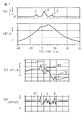
図3(A)〜(D)は、近接パイロット噴射、メイン噴射、アフター噴射からなるマルチ燃料噴射を行った場合の、筒内圧センサ29a〜29dで検出した燃焼室内圧力とその変化率とのクランク角(横軸)に対する変化を示すタイミング図である。
【0047】
図3において、図3(A)は燃料噴射弁のバルブリフト(略燃料噴射率に等しい)を示し、図3(A)のIは近接パイロット噴射、IIはメイン噴射、IIIはアフター噴射を示している。
【0048】
図3(B)は、筒内圧センサで検出した燃焼室内圧力Pの変化を示す。図3(B)に示すように単に燃焼室内圧力Pから見たのでは近接パイロット噴射、メイン噴射、アフター噴射のそれぞれの噴射による圧力変化は互いに重複、干渉しあっており、それぞれの噴射に対応するピークを判別することはできない。
【0049】
図3(C)は、図3(B)の燃焼室内圧力Pのクランク角に対する一次変化率(dP/dθ)を示す図である。図3(C)から判るように、圧力Pの一次変化率(dP/dθ)をとることにより、近接パイロット噴射、メイン噴射、アフター噴射に対するピーク(I、II、III)が明確に分離され判別可能となっている。圧力Pの一次変化率(dP/dθ)は圧力の上昇速度であり、その極大値(ピーク値)は、それぞれの噴射における噴射量と相関があることが判明している。このため、圧力Pの一次変化率のピーク値からそれぞれの噴射における実際の噴射量を個別に判別することができる。
【0050】
次に、図3(D)は圧力Pのクランク角に対する二次変化率(d2P/dθ2)を示す図である。図3(D)に示すように圧力Pの二次変化率(d2P/dθ2)もそれぞれの噴射に対応する明確なピーク(図3(D)I〜III)を有している。
【0051】
圧力Pの二次変化率におけるピーク値は、圧力Pの一次変化率すなわち圧力上昇速度の変化の極大値、すなわち各噴射における燃料の燃焼開始時の圧力上昇速度の変化率を示している。このため、(d2P/dθ2)がある基準値を越えた場合には、急激な圧力上昇が開始されたこと、すなわち燃焼が開始されたと判断することができる。
本実施形態では、圧力Pの二次変化率が図3(D)に示す一定の基準値P0”を越えた場合に燃焼が開始されたと判定する。
【0052】
なお、圧力Pの一次変化率(dP/dθ)も図3(C)に示すように各噴射に対応する明確なピークを示しており、(dP/dθ)は燃焼室内の圧力上昇速度を表すのであるから、理論的には圧力Pの圧力上昇速度(dP/dθ)が所定の基準値を越えたときに燃焼が開始されたと判断することも可能である。
【0053】
しかし、圧力Pの一次変化率(dP/dθ)のピーク値は近接パイロット噴射、メイン噴射、アフター噴射それぞれで大きく異なっているため、(dP/dθ)を用いてそれぞれの燃料噴射開始の有無を判定するためには各噴射毎に燃焼開始判定用の基準値を設ける必要がある。
【0054】
これに対して、圧力Pの二次変化率(d2P/dθ2)を用いると、それぞれの噴射に対応するピーク値は略同じ値となるため、全部の噴射に対して共通の基準値(図3(D)P0”)を用いて燃焼開始の判定を行うことができる利点がある。なお、図3(A)から(D)は近接パイロット噴射、メイン噴射、アフター噴射のみを行った場合について示しているが、他に早期パイロット噴射、ポスト噴射がある場合についても同一の判定値(図3(D)P0”)で燃焼開始の有無を判定することができる。
【0055】
次に、本実施形態における燃料噴射量と噴射時期とのフィードバック制御について説明する。
本実施形態では、以下の手順で各燃料噴射の噴射量と噴射時期とを制御する。
(1)基本燃料噴射量、噴射時期の設定
本実施形態では、ECU20はクランク角センサ25の出力から算出した機関回転数と、アクセル開度センサ21で検出したアクセル開度とから、予め定めた関係に基づいてマルチ燃料噴射の各噴射の基本噴射量と基本噴射時期とを設定する。それぞれの噴射の基本(目標)噴射量と基本(目標)噴射時期とは、機関回転数とアクセル開度とを用いた二次元数値テーブルとしてECU20のROMに予め格納されている。この基本噴射量、噴射時期の設定方法は公知のいかなる方法をも使用可能であるので、ここでは詳細な説明は省略する。
【0056】
(2)各燃料噴射の燃焼確認と燃料噴射量の調整
上記基本噴射量と基本噴射時期とで各燃料噴射を行った場合に、燃焼が生じているか否かを燃焼室圧力Pの二次変化率(d2P/dθ2)が基準値P0”を越えているか否かに基づいて判断し、基準値を越えていない場合には対応する噴射の燃料噴射量を増大させる。
【0057】
例えば、図3の例で仮に図3(D)で(d2P/dθ2)のIに相当するピークがない場合、すなわち近接パイロット噴射開始からメイン噴射開始までの間で(d2P/dθ2)が基準値を越えなかった場合には、近接パイロット噴射がされていないか、或いは噴射量が不足していることになる。このため、この場合には、Iに相当する部分で(d2P/dθ2)が基準値P0”を越えるまで近接パイロット噴射の噴射量を増大する。
【0058】
また、図3(D)でIII(アフター噴射)に相当するピークがない場合、すなわちメイン噴射終了後に(d2P/dθ2)が基準値を越えなかった場合には、アフター噴射がされていないか、或いは噴射量が不足していると判断し、メイン噴射後に(d2P/dθ2)が基準値を越えるまでアフター噴射の噴射量を増大する。
上記の操作を各噴射に対応する圧力の二次変化率(d2P/dθ2)の値が基準値P0”を越えるまで行うことより、各噴射で噴射された燃料が確実に燃焼するようになる。
【0059】
(3)噴射時期の調整
上記の操作により、各噴射に対応する圧力の二次変化率(d2P/dθ2)が全て基準値P0”を越えた場合には、次に(d2P/dθ2)が基準値P0”を越えるクランク角が、(1)で設定した基本噴射時期に一致するように各噴射の噴射時期を調整する。これにより、各噴射の噴射時期が目標噴射時期(本実施形態では基本噴射時期)にフィードバック制御される。
【0060】
(4)噴射量の最終調整
上記の操作終了後、(2)で調整した各噴射の噴射量を、各噴射に対応する圧力の一次変化率(dP/dθ)をそれぞれの噴射の基準値と比較することにより調整される。
【0061】
本実施形態では各噴射の基準値として予め上限値が設定されており、各燃料噴射に対応する(dP/dθ)がそれぞれの上限値を越えないように、すなわち各燃料噴射に対応する燃焼における圧力上昇速度が過大にならないように噴射量が調整される。ここでそれぞれの噴射に対応する基準値(上限値)は、各運転条件(機関回転数とアクセル開度との組み合わせ)において予め実験等により最適な燃焼が得られる(dP/dθ)の上限値として求められており、マルチ燃料噴射の各噴射毎に機関回転数とアクセル開度とを用いた数値テーブルとしてECU20のROMに格納されている。
【0062】
また、この場合噴射量の調整は必ずしも(dP/dθ)が上限値を越えた噴射に対してのみ行うわけではなく、他の噴射についても行い、最終的に各噴射に対応する(dP/dθ)の値が全てそれぞれの上限値以下になるように、各噴射量を調整する。
【0063】
例えば、図3の例で説明すると、仮にパイロット噴射に対する(dP/dθ)の値(図3(C)I)が上限値(図3、P1′)を越えている場合には、パイロット噴射量が過大になっていると判断できるため、パイロット噴射量そのものを減量して、(dP/dθ)が上限値P1′以下になるようにする。
【0064】
また、アフター噴射に対する(dP/dθ)の値(図3(C)III)が上限値(図3、P3′)を越えている場合には、同様にアフター噴射の噴射量を減量して(dP/dθ)が上限値P3′以下になるようにする。
【0065】
しかし、メイン噴射に対する(dP/dθ)の値(図3(C)II)が上限値P2′を越えている場合には、メイン噴射そのものの噴射量を調整するのではなく、パイロット噴射の噴射量を増大する。これは、メイン噴射に対応する(dP/dθ)が上限値P2′を越えたと言うことは、パイロット噴射量が不十分であるためにメイン噴射の燃料の着火遅れが大きくなり、そのために圧力上昇速度が過大になっていると考えられるからである。
【0066】
以上の操作を行って、各燃料噴射に対する圧力の一次変化率の値が全てそれぞれの基準範囲内(本実施形態では上限値以下)になるように各燃料噴射の噴射量を調整することにより、各燃料噴射の噴射量が最適な値にフィードバック制御される。
【0067】
図4は、上記(2)から(4)に相当する制御操作を示すフローチャートである。本操作はECU20により一定間隔(一定クランク角)毎に実行される。
【0068】
図4において、ステップ401とステップ403とは、それぞれ(dP/dθ)と(d2P/dθ2)との算出操作を示している。
【0069】
本実施形態では、燃焼室内圧力Pの一次変化率(dP/dθ)と二次変化率(d2P/dθ2)とは、それぞれ次式で算出される。
【0070】
(dP/dθ)=Pn−P(n−1)
(d2P/dθ2)=(P(n)−2P(n−1)+P(n−2))
ここで、Pnは、筒内圧センサ29a〜29dで検出した燃焼室内圧力を示す。本実施形態では、ECU20は一定クランク角毎に筒内圧センサ出力をサンプリングしており、Pnは今回サンプリングした燃焼室内圧力、P(n−1)は前回サンプリングした燃焼室内圧力、P(n−2)は前々回にサンプリングした燃焼室内圧力である。
【0071】
次いでステップ405、407では上記(2)で説明した各燃料噴射の燃焼確認と燃料噴射量の調整が行われる。すなわち、ステップ405では各燃料噴射に対応する圧力二次変化率(d2P/dθ2)が共通の基準値P0”と比較され、基準値に到達していない場合には、基準値に到達するまで対応する噴射の噴射量が増大される(ステップ407)。
【0072】
ステップ409は、上記(3)で説明した噴射時期の調整操作である。すなわち、ステップ409では各噴射に対応する二次変化率(d2P/dθ2)が基準値P0”より大きくなるクランク角が、機関回転数とアクセル開度とから定まる基本噴射時期に一致するように各噴射の噴射時期が調整される。
【0073】
ステップ409で噴射時期の調整終了後、ステップ411では上記(4)で説明した噴射量の最終調整が行われ、各噴射に対応する(dP/dθ)の値が全てそれぞれの基準範囲(上限値以下)になるように各噴射の噴射量が調整される。
【0074】
なお、上述の実施形態では、図3の近接パイロット噴射、メイン噴射、アフター噴射のみを行う場合について説明したが、他に早期パイロット噴射(複数回の場合を含む)やポスト噴射を行う場合も同様な制御が可能である。
【0075】
なお、早期パイロット噴射を行った場合に、早期パイロット噴射の噴射量が少ない場合などは早期パイロット噴射に対する(dP/dθ)や(d2P/dθ2)のピークが明確に現れない場合があり得る。このような場合は、通常近接パイロット噴射に対応する(dP/dθ)が上限値P1′を越えており近接パイロット噴射の噴射量が多すぎると判定されるにもかかわらず、メイン噴射に対応する(dP/dθ)が上限値P2′を越えてしまいパイロット噴射量が不足すると判断される。このような場合には、早期パイロット噴射の噴射量が不足していると判断することができるため、早期パイロット噴射の噴射量を増量することにより、各燃料噴射に対応する(dP/dθ)が全て上限値以下になるように調整される。
【0076】
また、上述したように、図4の操作では、簡易な演算(差分計算)で算出可能な圧力の一次変化率と二次変化率とを用いて噴射量と噴射時期との調整を行い、しかも、算出した一次変化率と二次変化率とが予め定めた基準値を越えているか否かの判断のみで噴射量、噴射時期の調整ができ、煩雑な操作を行いこれらの値の極大値や極小値を求める必要がない。このため、ECU20の計算負荷が増大することが防止され、簡易かつ確実に各噴射の噴射量と噴射時期とを正確に調節することができる。
また、本実施形態ではマルチ燃料噴射の各噴射量と噴射時期とがフィードバック制御されるため、例えば燃料噴射弁の公差による燃料噴射特性の個体間ばらつきが比較的大きい場合や、或いは使用とともに燃料噴射特性が変化するような場合であっても各燃料噴射を正確に制御することができる。このため、コモンレール式燃料噴射装置においても、燃料噴射弁の特性のばらつきをある程度許容することができ、従来のように燃料噴射弁の特性のばらつきを厳しく管理する必要がなくなるため、燃料噴射弁のコストを低減することが可能となる。
【0077】
【発明の効果】
各請求項に記載の発明によれば、マルチ燃料噴射を行う機関においても各燃料噴射の噴射量と噴射時期とを適正な値にフィードバック制御することが可能となるという共通の効果を奏する。
【図面の簡単な説明】
【図1】本発明を自動車用4気筒ディーゼル機関に適用した実施形態の概略構成を示す図である。
【図2】マルチ燃料噴射を構成する各燃料噴射を説明する図である。
【図3】本発明における各燃料噴射の噴射量と噴射時期との調整の原理を説明する図である。
【図4】燃料噴射制御操作の一例を説明するフローチャートである。
【符号の説明】
1…ディーゼル機関
3…コモンレール
10a〜10d…筒内燃料噴射弁
20…電子制御ユニット(ECU)
21…アクセル開度センサ
25…クランク角センサ
29a〜29d…筒内圧センサ[0001]
TECHNICAL FIELD OF THE INVENTION
The present invention relates to a fuel injection control device for an internal combustion engine, and more particularly, to a fuel injection control device that optimizes combustion of a diesel engine.
[0002]
[Prior art]
In recent years, demands for stricter exhaust gas regulations and requirements for noise reduction have increased demands for diesel engines to optimize combustion in a combustion chamber. In order to optimize combustion, it is necessary to accurately control the fuel injection amount, fuel injection timing, injection period, and the like even in a diesel engine.
[0003]
However, in diesel engines, combustion is performed in a lean air-fuel ratio region that is considerably higher than the stoichiometric air-fuel ratio, and it was not necessary to maintain the air-fuel ratio exactly at the target air-fuel ratio, unlike gasoline engines. Fuel injection parameters such as quantity and fuel injection timing are not as precisely controlled as gasoline engines. Conventionally, in a diesel engine, target values such as a fuel injection amount, an injection timing, an injection pressure, an EGR gas amount, and the like are determined from engine operating conditions (rotational speed, accelerator opening, etc.), and a fuel injection valve is determined in accordance with the target value. Although the open loop control does not prevent the actual fuel injection amount from producing an error with respect to the target injection amount, it is not possible to accurately control the combustion state to the target state. It was difficult.
[0004]
Furthermore, in order to improve exhaust gas properties and reduce noise, it is effective to use multiple fuel injections that perform multiple fuel injections before and after the main fuel injection during one cycle of each cylinder to adjust the combustion state optimally. It is. However, in order to perform multi-fuel injection, it is necessary to precisely control the fuel injection amount and the injection timing of each of the multiple fuel injections.
[0005]
In addition, the common-rail high-pressure fuel injection system, which has recently been used in diesel engines to improve the combustion state, has a short fuel injection time and changes the fuel injection pressure during injection. There is a problem that an error easily occurs. For this reason, in the common rail type high-pressure fuel injection device, measures such as setting the tolerance of the fuel injection valve to be small to improve the fuel injection accuracy are taken. In both cases, since the fuel injection characteristics change, it is difficult to always accurately match the fuel injection amount to the target value.
[0006]
As described above, in a diesel engine, an error easily occurs in the fuel injection amount and the like, so that even if a target value for obtaining an optimum combustion state can be set, it is difficult to actually match the fuel injection amount to the target value. .
In order to match the combustion state to the target combustion state, the actual combustion state is detected in some form, and the fuel injection amount and fuel injection timing are adjusted so that the actual combustion state matches the target combustion state. It is effective to feedback control the fuel injection parameters.
[0007]
As described above, an example of a combustion control apparatus for an internal combustion engine that detects a combustion state and performs feedback control of a fuel injection parameter is described in
[0008]
The device of
[0009]
That is, the apparatus of
[0010]
[Patent Document 1]
JP 2001-123881 A
[0011]
[Problems to be solved by the invention]
In the device disclosed in
[0012]
That is, in order to obtain good exhaust properties, it is necessary to appropriately control not only the pilot injection amount but also the injection timing. However, in the device of
[0013]
Further, since the device of
[0014]
SUMMARY OF THE INVENTION The present invention has been made in view of the above-described problems of the related art, and has been made in consideration of the above-described problems. It is intended to provide.
[0015]
[Means for Solving the Problems]
According to the first aspect of the present invention, there is provided an internal combustion engine that performs multi-fuel injection in which fuel is injected into an engine combustion chamber before or after main fuel injection or both before and after main fuel injection in addition to main fuel injection. A fuel injection control device, comprising: an in-cylinder pressure sensor that detects a pressure in an engine combustion chamber, and calculating a primary change rate and a secondary change rate of a combustion chamber pressure detected by the in-cylinder pressure sensor with respect to a crank angle or time. It is determined whether the injection amount of each fuel injection in the multiple fuel injection is an appropriate value based on the calculated temporary change rate, and the combustion start timing in the combustion chamber is determined based on the calculated secondary change rate. A fuel injection control device for an internal combustion engine is provided that determines whether or not the fuel injection is appropriate and controls an injection amount and an injection timing of each fuel injection of the multi-fuel injection according to the determination result.
[0016]
That is, in the first aspect of the present invention, the change rate of the combustion chamber pressure P detected by the in-cylinder pressure sensor (the change rate (dP / dθ) and (d2P / dθ2) with respect to the crank angle θ, or the change rate (dP / dt) with respect to time t. ) And (d2P / dt2)), the injection amount and the injection timing of each fuel injection in the multiple fuel injection are controlled. Hereinafter, the case of the change rate with respect to the crank angle will be described. However, the case where the change rate with respect to time is used is the same as the following description.
[0017]
When the fuel injected into the combustion chamber burns, the pressure in the combustion chamber increases. For this reason, the value of the pressure change rate (dP / dθ) in the combustion chamber increases every time each fuel injection of the multiple fuel injection is performed, and a peak corresponding to each injection (dP / dθ) is generated.
It has been found that the magnitude of this peak has a correlation with the fuel injection amount.
[0018]
When multiple fuel injection is performed, a plurality of fuel injections are performed for one stroke cycle. However, when the fuel injected by each fuel injection burns, the combustion pressure increases. There should be a peak corresponding to the combustion of the fuel injected by the fuel injection. However, in actuality, especially in the case of a short interval between fuel injections in multi-fuel injection, the pressure rise in the combustion chamber is caused by each injection, and the pressure peak corresponding to each fuel injection is increased. Is difficult to separate.
[0019]
On the other hand, the pressure change rate (dP / dθ) has a distinct peak value for each fuel injection. For this reason, even when multiple fuel injections are performed using (dP / dθ), it is possible to individually determine the injection amount of each injection, so that accurate feedback control of the injection amount can be performed.
[0020]
Further, the secondary change rate (d2P / dθ2) of the pressure in the combustion chamber also exists for each fuel injection similarly to the primary change rate. Further, since the secondary change rate of the pressure in the combustion chamber has a peak corresponding to the time when the pressure at the start of combustion starts to increase, it is difficult to determine the pressure in the combustion chamber itself or the pressure change rate (dP / dθ). The combustion start timing corresponding to each fuel injection can also be clearly determined. Therefore, even when multiple fuel injection is performed, the combustion start timing corresponding to each injection can be individually determined using the secondary pressure change rate (d2P / dθ2). Feedback control can be performed.
[0021]
According to the second aspect of the present invention, a point in time at which the secondary change rate exceeds a predetermined reference value is determined as a combustion start timing of the fuel injected by each fuel injection, and the combustion start timing is determined as the engine operation time. 2. The fuel injection control device for an internal combustion engine according to
[0022]
That is, according to the second aspect of the present invention, the time when the secondary change rate of the pressure in the combustion chamber exceeds a predetermined reference value is determined as the combustion start timing in the combustion chamber. Although the peak of the secondary change rate of the pressure corresponds to the combustion start time, in the present invention, the time when the secondary change rate increases and becomes equal to or more than the reference value instead of detecting the local maximum value is defined as the combustion start time. Judgment is made, and the injection timing of each fuel injection is feedback-controlled so that the detected combustion start timing coincides with the optimum combustion timing obtained in advance through experiments or the like. As described above, since it is not necessary to perform the peak detection (maximum value detection) of the secondary change rate by determining whether the secondary pressure change rate is equal to or more than the reference value, the combustion start timing can be easily determined. Therefore, the calculation load on the control device can be reduced.
[0023]
According to the invention described in
[0024]
That is, in
[0025]
In the present invention, when the injection amount of all fuel injections becomes appropriate, the reference range of the primary change rate of the pressure corresponding to each fuel injection is determined in advance by experiments or the like, and the reference range corresponding to each fuel injection during engine operation is set. The injection amount of each fuel injection is controlled so that the primary change rate of the applied pressure falls within this reference range. As a result, the fuel injection amount of all the fuel injections is controlled to an appropriate value.
[0026]
BEST MODE FOR CARRYING OUT THE INVENTION
Hereinafter, embodiments of the present invention will be described with reference to the accompanying drawings.
FIG. 1 is a diagram showing a schematic configuration of an embodiment when the fuel injection device of the present invention is applied to a diesel engine for an automobile.
[0027]
In FIG. 1,
[0028]
In FIG. 1,
[0029]
In order to perform these controls, in the present embodiment, the
[0030]
The
[0031]
In FIG. 1, reference numerals 29a to 29d denote in-cylinder pressure sensors of a known type which are disposed in the respective cylinders 10a to 10d and detect the pressure in the cylinder combustion chamber. Each combustion chamber pressure detected by the in-cylinder pressure sensors 29a to 29d is supplied to the
[0032]
In the present embodiment, the fuel pressure of the
[0033]
FIG. 2 is a diagram illustrating each fuel injection constituting the multi-fuel injection according to the present embodiment.
[0034]
In FIG. 2, the horizontal axis represents the crank angle (CA), and the TDC on the horizontal axis represents the compression top dead center. The vertical axis in FIG. 2 represents the injection rate of each fuel injection, and the area of each peak roughly indicates the relative fuel injection amount of each fuel injection. As shown in the figure, in the multiple fuel injection, all or a part of the early pilot injection, the proximity pilot injection, the main injection (main fuel injection), the after injection, the post injection, and the like are performed.
[0035]
Hereinafter, each fuel injection other than the main injection will be briefly described.
(1) Early pilot injection
The early pilot injection is pilot injection performed at a considerably earlier timing than the main injection (for example, at a timing earlier than the start of the main injection by a crank angle of 20 degrees (20 ° CA) or more). The fuel injected by the early pilot injection forms a premixed gas, and is compressed and ignited. X By performing early pilot injection with little generation of particulates or particulates, exhaust properties can be improved. In addition, the early pilot injection raises the temperature and pressure in the combustion chamber and shortens the ignition delay period of the proximity pilot injection and the main injection, which will be described later. X Generation can be suppressed.
[0036]
Since the early pilot injection is performed at a time when the temperature and pressure in the combustion chamber are relatively low, when the injection amount is large, the injected fuel reaches the cylinder wall in a liquid state and causes problems such as lubrication oil dilution. . For this reason, in the early pilot injection, when the injection amount is large, the required injection amount is divided into a plurality of injections and the small amount is injected little by little to prevent the liquid fuel from reaching the cylinder wall.
[0037]
(2) Proximity pilot injection
Proximity pilot injection is pilot injection performed immediately before main injection (for example, within 20 ° CA from the start of main injection). Proximity pilot injection generates less hydrocarbons as compared to early pilot injection, and similarly to early pilot injection, shortens the ignition delay period of main injection and reduces noise and NO of main injection. X Generation can be suppressed.
[0038]
(3) After injection
The after-injection is an injection started immediately after the end of the main injection or at a relatively short interval (for example, within 15 ° CA after the end of the main injection).
The after-injection is performed for the purpose of improving the combustion by increasing the temperature, pressure, turbulence, and the like in the combustion chamber again at a later stage of the combustion of the fuel of the main injection, and reducing the injection amount of the main injection.
[0039]
That is, in the later stage of the main injection combustion, the temperature and pressure in the combustion chamber are reduced, and the turbulence in the cylinder is reduced. By performing the after-injection in this state, the turbulence due to the fuel injection increases and the temperature and pressure increase due to the combustion of the injected fuel, so that the atmosphere in the combustion chamber is improved to promote the combustion. Further, since the injection amount of the main injection can be reduced by the injection amount of the after injection, the generation of a locally rich region generated by the main injection fuel is suppressed. Also, by appropriately setting the amount and timing of the after-injection, the main injection amount can be reduced and the maximum in-cylinder temperature due to combustion can be reduced. X Has the effect of suppressing generation of
[0040]
(4) Post injection
Post-injection is fuel injection that is started at a relatively long interval after the end of the main injection (for example, 15 ° CA or more after the end of the main injection). The main purpose of post-injection is to increase exhaust temperature and pressure.
[0041]
For example, in the case where the temperature of the exhaust gas purification catalyst disposed in the exhaust system is low and does not reach the activation temperature and the exhaust gas purification action cannot be obtained, the exhaust temperature is increased by performing post-injection, and the catalyst is quickly reduced. The temperature can be raised to the activation temperature. In addition, since post-injection increases the temperature and pressure of exhaust gas, engines with a turbocharger increase the work of the turbine to improve the acceleration performance by increasing the supercharging pressure and to suppress the effects of smoke during acceleration. Obtainable.
Further, as an exhaust gas purifying catalyst, NO in exhaust gas using HC components is used. X When a selective reduction catalyst for purifying NO is used, HC is supplied to the catalyst by performing post injection to make NO X Purification rate can be improved.
[0042]
By performing the multi-fuel injection as described above, it is possible to significantly improve the exhaust characteristics and noise of the diesel engine. It is necessary to precisely control the injection timing. For example, in the proximity pilot injection in which the accuracy of the injection amount and the injection timing is required most, the amount of one fuel injection is 1.5 to 2.5 mm. 3 It is necessary to control the injection timing within about ± 2 ° CA.
As described above, since the fuel injection valve has variations among individuals due to tolerances and changes in fuel injection characteristics depending on the service period, the accuracy of fuel injection cannot be improved by ordinary open loop control.
[0043]
Further, for example, even if the fuel injection is controlled based on the combustion noise as in the above-mentioned
In particular, in the multi-fuel injection, the above-described fuel injection of the proximity pilot injection, the main injection, and the after-injection may be performed consecutively when the injection interval is extremely short. There is a problem that the injection amounts of these three injections cannot be separated and determined even by only the above.
[0044]
In the present embodiment, each fuel injection is performed using a primary change rate (differential value) and a secondary change rate (second-order differential value) of the pressure in the combustion chamber detected with the in-cylinder pressure sensors 29a to 29d with respect to the crank angle or time. By controlling the injection amount and the injection timing of each of these, it is possible to accurately control each fuel injection.
[0045]
In the following description, an example is described in which fuel injection is controlled using the primary change rate and the secondary change rate ((dP / dθ) and (d2P / dθ2)) of the pressure P in the combustion chamber with respect to the crank angle θ. However, exactly the same control is possible when the primary change rate and the secondary change rate of the pressure in the combustion chamber with respect to time are used.
[0046]
FIGS. 3 (A) to 3 (D) show cranks of the pressure in the combustion chamber detected by the in-cylinder pressure sensors 29a to 29d and the rate of change thereof in the case of performing the multi-fuel injection including the close pilot injection, the main injection, and the after injection. FIG. 7 is a timing chart showing a change with respect to an angle (horizontal axis).
[0047]
In FIG. 3, FIG. 3 (A) shows the valve lift of the fuel injection valve (substantially equal to the fuel injection rate), I in FIG. 3 (A) shows the proximity pilot injection, II shows the main injection, and III shows the after injection. ing.
[0048]
FIG. 3B shows a change in the pressure P in the combustion chamber detected by the in-cylinder pressure sensor. As shown in FIG. 3 (B), the pressure changes due to the proximity pilot injection, the main injection, and the after-injection overlap with each other and interfere with each other when viewed simply from the pressure P in the combustion chamber. It is not possible to determine the peak that occurs.
[0049]
FIG. 3C is a diagram showing a primary change rate (dP / dθ) with respect to the crank angle of the combustion chamber pressure P in FIG. 3B. As can be seen from FIG. 3 (C), by taking the primary rate of change (dP / dθ) of the pressure P, the peaks (I, II, III) for the proximity pilot injection, the main injection, and the after injection are clearly separated and determined. It is possible. The primary rate of change (dP / dθ) of the pressure P is the rate of increase of the pressure, and it has been found that the maximum value (peak value) has a correlation with the injection amount in each injection. Therefore, the actual injection amount of each injection can be individually determined from the peak value of the primary change rate of the pressure P.
[0050]
Next, FIG. 3D is a diagram showing a secondary change rate (d2P / dθ2) of the pressure P with respect to the crank angle. As shown in FIG. 3 (D), the secondary change rate (d2P / dθ2) of the pressure P also has a clear peak (FIG. 3 (D) I to III) corresponding to each injection.
[0051]
The peak value of the secondary change rate of the pressure P indicates the primary change rate of the pressure P, that is, the maximum value of the change of the pressure rise rate, that is, the change rate of the pressure rise rate at the start of fuel combustion in each injection. Therefore, when (d2P / dθ2) exceeds a certain reference value, it can be determined that a rapid pressure increase has started, that is, combustion has started.
In the present embodiment, it is determined that the combustion has started when the secondary change rate of the pressure P exceeds a certain reference value P0 ″ shown in FIG.
[0052]
The primary change rate (dP / dθ) of the pressure P also shows a clear peak corresponding to each injection as shown in FIG. 3 (C), and (dP / dθ) represents the pressure rise rate in the combustion chamber. Therefore, it is theoretically possible to determine that the combustion has started when the pressure rise rate (dP / dθ) of the pressure P exceeds a predetermined reference value.
[0053]
However, since the peak value of the primary change rate (dP / dθ) of the pressure P is significantly different between the proximity pilot injection, the main injection, and the after injection, the presence or absence of the start of each fuel injection is determined using (dP / dθ). To make the determination, it is necessary to provide a reference value for determining the start of combustion for each injection.
[0054]
On the other hand, when the secondary change rate of the pressure P (d2P / dθ2) is used, the peak value corresponding to each injection becomes substantially the same value, and therefore, the reference value common to all the injections (FIG. 3) (D) P0 ″) has the advantage that the determination of the start of combustion can be made. FIGS. 3A to 3D show the case where only the proximity pilot injection, the main injection, and the after injection are performed. However, the presence / absence of the start of combustion can be determined with the same determination value (P0 ″ in FIG. 3 (D)) even when there are other early pilot injections and post injections.
[0055]
Next, feedback control of the fuel injection amount and the injection timing in the present embodiment will be described.
In the present embodiment, the injection amount and the injection timing of each fuel injection are controlled by the following procedure.
(1) Setting of basic fuel injection amount and injection timing
In the present embodiment, the
[0056]
(2) Confirmation of combustion of each fuel injection and adjustment of fuel injection amount
When each fuel injection is performed with the basic injection amount and the basic injection timing, it is determined whether or not combustion is occurring by determining whether the secondary change rate (d2P / dθ2) of the combustion chamber pressure P exceeds the reference value P0 ″. The determination is made based on whether or not the fuel injection amount is not larger than the reference value, and the fuel injection amount of the corresponding injection is increased.
[0057]
For example, in the example of FIG. 3, if there is no peak corresponding to I of (d2P / dθ2) in FIG. 3D, that is, (d2P / dθ2) is the reference value from the start of the proximity pilot injection to the start of the main injection. Does not exceed, it means that the proximity pilot injection has not been performed or the injection amount is insufficient. Therefore, in this case, the injection amount of the proximity pilot injection is increased until (d2P / dθ2) exceeds the reference value P0 ″ in the portion corresponding to I.
[0058]
If there is no peak corresponding to III (after-injection) in FIG. 3D, that is, if (d2P / dθ2) does not exceed the reference value after the end of main injection, it is determined whether after-injection has been performed. Alternatively, it is determined that the injection amount is insufficient, and the injection amount of the after injection is increased until (d2P / dθ2) exceeds the reference value after the main injection.
By performing the above operation until the value of the secondary change rate (d2P / dθ2) of the pressure corresponding to each injection exceeds the reference value P0 ″, the fuel injected by each injection is surely burned.
[0059]
(3) Adjustment of injection timing
By the above operation, when all the secondary change rates (d2P / dθ2) of the pressures corresponding to the respective injections exceed the reference value P0 ″, then the crank angle at which (d2P / dθ2) exceeds the reference value P0 ″ However, the injection timing of each injection is adjusted so as to match the basic injection timing set in (1). Thus, the injection timing of each injection is feedback-controlled to the target injection timing (the basic injection timing in the present embodiment).
[0060]
(4) Final adjustment of injection amount
After the above operation, the injection amount of each injection adjusted in (2) is adjusted by comparing the primary change rate (dP / dθ) of the pressure corresponding to each injection with the reference value of each injection.
[0061]
In the present embodiment, an upper limit is set in advance as a reference value for each injection, and (dP / dθ) corresponding to each fuel injection does not exceed the respective upper limit, that is, in the combustion corresponding to each fuel injection. The injection amount is adjusted so that the pressure rise rate does not become excessive. Here, the reference value (upper limit value) corresponding to each injection is the upper limit value (dP / dθ) at which optimal combustion is obtained in advance by experiments or the like under each operating condition (combination of engine speed and accelerator opening). And stored in the ROM of the
[0062]
In this case, the adjustment of the injection amount is not necessarily performed only for the injection in which (dP / dθ) exceeds the upper limit, but is also performed for other injections and finally corresponds to each injection (dP / dθ). The injection amounts are adjusted so that the values of the above ()) are all equal to or less than the respective upper limit values.
[0063]
For example, in the example of FIG. 3, if the value of (dP / dθ) for pilot injection (FIG. 3 (C) I) exceeds the upper limit (FIG. 3, P1 ′), the pilot injection amount Is determined to be excessive, the pilot injection amount itself is reduced so that (dP / dθ) becomes equal to or less than the upper limit value P1 ′.
[0064]
When the value of (dP / dθ) (FIG. 3 (C) III) with respect to the after-injection exceeds the upper limit (FIG. 3, P3 ′), the after-injection injection amount is similarly reduced ( dP / dθ) is not more than the upper limit value P3 ′.
[0065]
However, if the value of (dP / dθ) for the main injection (II in FIG. 3 (C)) exceeds the upper limit P2 ′, the injection amount of the main injection itself is not adjusted but the pilot injection is performed. Increase volume. This means that (dP / dθ) corresponding to the main injection has exceeded the upper limit value P2 ′, which means that the ignition delay of the fuel for the main injection becomes large due to the insufficient pilot injection amount, and therefore the pressure rise This is because the speed is considered to be excessive.
[0066]
By performing the above operation, the injection amount of each fuel injection is adjusted so that the value of the primary change rate of the pressure for each fuel injection is all within the respective reference ranges (in the present embodiment, not more than the upper limit value). The injection amount of each fuel injection is feedback-controlled to an optimal value.
[0067]
FIG. 4 is a flowchart showing a control operation corresponding to the above (2) to (4). This operation is executed by the
[0068]
In FIG. 4,
[0069]
In the present embodiment, the primary change rate (dP / dθ) and the secondary change rate (d2P / dθ2) of the pressure P in the combustion chamber are calculated by the following equations.
[0070]
(DP / dθ) = Pn-P (n-1)
(D2P / dθ2) = (P (n) −2P (n−1) + P (n−2))
Here, Pn indicates the pressure in the combustion chamber detected by the in-cylinder pressure sensors 29a to 29d. In this embodiment, the
[0071]
Next, in
[0072]
Step 409 is the adjustment operation of the injection timing described in the above (3). That is, in
[0073]
After the adjustment of the injection timing is completed in
[0074]
In the above-described embodiment, the case of performing only the close pilot injection, the main injection, and the after injection in FIG. 3 has been described. However, the same applies to the case of performing the early pilot injection (including a plurality of times) and the post injection. Control is possible.
[0075]
When the early pilot injection is performed and the injection amount of the early pilot injection is small, the peak of (dP / dθ) or (d2P / dθ2) for the early pilot injection may not clearly appear. In such a case, despite the fact that (dP / dθ) corresponding to the normal pilot injection exceeds the upper limit value P1 ′ and it is determined that the injection amount of the close pilot injection is too large, it corresponds to the main injection. (DP / dθ) exceeds the upper limit value P2 ′, and it is determined that the pilot injection amount is insufficient. In such a case, it can be determined that the injection amount of the early pilot injection is insufficient. Therefore, by increasing the injection amount of the early pilot injection, (dP / dθ) corresponding to each fuel injection can be determined. All are adjusted to be less than the upper limit.
[0076]
In addition, as described above, in the operation of FIG. 4, the injection amount and the injection timing are adjusted using the primary change rate and the secondary change rate of the pressure that can be calculated by a simple calculation (difference calculation), and The injection amount and the injection timing can be adjusted only by determining whether the calculated primary change rate and secondary change rate exceed a predetermined reference value, and a complicated operation can be performed to achieve the maximum value of these values or There is no need to find a local minimum. For this reason, the calculation load of the
Further, in the present embodiment, since the injection amount and the injection timing of the multi-fuel injection are feedback-controlled, for example, when the variation between individual fuel injection characteristics due to the tolerance of the fuel injection valve is relatively large, Even when the characteristics change, each fuel injection can be accurately controlled. For this reason, even in the common rail type fuel injection device, variations in the characteristics of the fuel injectors can be tolerated to some extent, and it is not necessary to strictly manage the variations in the characteristics of the fuel injectors as in the related art. Costs can be reduced.
[0077]
【The invention's effect】
According to the invention described in each of the claims, there is a common effect that the injection amount and the injection timing of each fuel injection can be feedback-controlled to appropriate values even in an engine that performs multi-fuel injection.
[Brief description of the drawings]
FIG. 1 is a diagram showing a schematic configuration of an embodiment in which the present invention is applied to a four-cylinder diesel engine for an automobile.
FIG. 2 is a diagram for explaining each fuel injection constituting multi-fuel injection.
FIG. 3 is a diagram illustrating the principle of adjusting the injection amount and the injection timing of each fuel injection according to the present invention.
FIG. 4 is a flowchart illustrating an example of a fuel injection control operation.
[Explanation of symbols]
1. Diesel engine
3… Common rail
10a to 10d: In-cylinder fuel injection valve
20 ... Electronic control unit (ECU)
21 ... Accelerator opening sensor
25 ... Crank angle sensor
29a-29d ... in-cylinder pressure sensor
Claims (3)
機関燃焼室内の圧力を検出する筒内圧センサを備え、
前記筒内圧センサで検出した燃焼室内圧力のクランク角または時間に対する一次変化率と二次変化率とを算出し、前記算出した一時変化率に基づいて前記マルチ燃料噴射におけるそれぞれの燃料噴射の噴射量が適切な値か否かを判定し、前記算出した二次変化率に基づいて燃焼室内の燃焼開始時期が適切か否かを判定するとともに、前記判定結果に応じて前記マルチ燃料噴射の各燃料噴射の噴射量と噴射時期とを制御する、内燃機関の燃料噴射制御装置。In addition to the main fuel injection, before or after the main fuel injection, or both before and after the fuel injection control device of the internal combustion engine performing multi-fuel injection to inject fuel into the engine combustion chamber,
Equipped with an in-cylinder pressure sensor that detects the pressure in the engine combustion chamber,
A primary change rate and a secondary change rate with respect to the crank angle or time of the pressure in the combustion chamber detected by the in-cylinder pressure sensor are calculated, and the injection amount of each fuel injection in the multi-fuel injection based on the calculated temporary change rate Is determined to be an appropriate value, and whether the combustion start timing in the combustion chamber is appropriate is determined based on the calculated secondary change rate, and each fuel of the multi-fuel injection is determined according to the determination result. A fuel injection control device for an internal combustion engine that controls an injection amount and an injection timing of an injection.
Priority Applications (1)
| Application Number | Priority Date | Filing Date | Title |
|---|---|---|---|
| JP2002263009A JP2004100557A (en) | 2002-09-09 | 2002-09-09 | Fuel injection control device of internal combustion engine |
Applications Claiming Priority (1)
| Application Number | Priority Date | Filing Date | Title |
|---|---|---|---|
| JP2002263009A JP2004100557A (en) | 2002-09-09 | 2002-09-09 | Fuel injection control device of internal combustion engine |
Publications (1)
| Publication Number | Publication Date |
|---|---|
| JP2004100557A true JP2004100557A (en) | 2004-04-02 |
Family
ID=32262885
Family Applications (1)
| Application Number | Title | Priority Date | Filing Date |
|---|---|---|---|
| JP2002263009A Pending JP2004100557A (en) | 2002-09-09 | 2002-09-09 | Fuel injection control device of internal combustion engine |
Country Status (1)
| Country | Link |
|---|---|
| JP (1) | JP2004100557A (en) |
Cited By (8)
| Publication number | Priority date | Publication date | Assignee | Title |
|---|---|---|---|---|
| JP2008050975A (en) * | 2006-08-23 | 2008-03-06 | Toyota Motor Corp | Start control device for internal combustion engine |
| JP2008111381A (en) * | 2006-10-31 | 2008-05-15 | Nissan Motor Co Ltd | Cylinder direct injection type internal combustion engine |
| JP2010138743A (en) * | 2008-12-10 | 2010-06-24 | Isuzu Motors Ltd | Diesel engine and control method for diesel engine |
| US7967118B2 (en) | 2004-08-31 | 2011-06-28 | Chen Dai-Heng | Impact absorber device |
| JP2013133812A (en) * | 2011-12-27 | 2013-07-08 | Honda Motor Co Ltd | Control device for compression-ignition internal combustion engine |
| JP2016145564A (en) * | 2015-02-09 | 2016-08-12 | 株式会社デンソー | Fuel injection control device |
| DE102017211271A1 (en) | 2016-07-06 | 2018-01-11 | Toyota Jidosha Kabushiki Kaisha | CONTROL SYSTEM OF AN INTERNAL COMBUSTION ENGINE |
| JP2018100623A (en) * | 2016-12-20 | 2018-06-28 | いすゞ自動車株式会社 | Fuel injection device of internal combustion engine and pre-injection control method |
-
2002
- 2002-09-09 JP JP2002263009A patent/JP2004100557A/en active Pending
Cited By (10)
| Publication number | Priority date | Publication date | Assignee | Title |
|---|---|---|---|---|
| US7967118B2 (en) | 2004-08-31 | 2011-06-28 | Chen Dai-Heng | Impact absorber device |
| JP2008050975A (en) * | 2006-08-23 | 2008-03-06 | Toyota Motor Corp | Start control device for internal combustion engine |
| JP2008111381A (en) * | 2006-10-31 | 2008-05-15 | Nissan Motor Co Ltd | Cylinder direct injection type internal combustion engine |
| JP2010138743A (en) * | 2008-12-10 | 2010-06-24 | Isuzu Motors Ltd | Diesel engine and control method for diesel engine |
| JP2013133812A (en) * | 2011-12-27 | 2013-07-08 | Honda Motor Co Ltd | Control device for compression-ignition internal combustion engine |
| JP2016145564A (en) * | 2015-02-09 | 2016-08-12 | 株式会社デンソー | Fuel injection control device |
| DE102017211271A1 (en) | 2016-07-06 | 2018-01-11 | Toyota Jidosha Kabushiki Kaisha | CONTROL SYSTEM OF AN INTERNAL COMBUSTION ENGINE |
| JP2018003780A (en) * | 2016-07-06 | 2018-01-11 | トヨタ自動車株式会社 | Control device of internal combustion engine |
| DE102017211271B4 (en) | 2016-07-06 | 2021-08-05 | Toyota Jidosha Kabushiki Kaisha | CONTROL SYSTEM OF AN COMBUSTION ENGINE |
| JP2018100623A (en) * | 2016-12-20 | 2018-06-28 | いすゞ自動車株式会社 | Fuel injection device of internal combustion engine and pre-injection control method |
Similar Documents
| Publication | Publication Date | Title |
|---|---|---|
| JP4415876B2 (en) | Control device for internal combustion engine | |
| US8620561B2 (en) | Control for internal combustion engine provided with cylinder halting mechanism | |
| CA2653750C (en) | Cetane number detection means and engine having the cetane number detection means | |
| US7950369B2 (en) | Internal combustion engine controlling apparatus | |
| EP1538325A1 (en) | Control device of internal combustion engine | |
| JP2004100566A (en) | Fuel injection control device of internal combustion engine | |
| JP3854209B2 (en) | Fuel injection control device for internal combustion engine | |
| JP4323907B2 (en) | Control device for internal combustion engine | |
| JP5110208B2 (en) | Combustion control device for internal combustion engine | |
| JP2009062862A (en) | Fuel injection control device of internal combustion engine | |
| JP2008163815A (en) | Fuel injection control device for internal combustion engine | |
| JP4136554B2 (en) | Fuel injection control device for internal combustion engine | |
| JP2004100557A (en) | Fuel injection control device of internal combustion engine | |
| WO2012105038A1 (en) | Fuel injection control device for internal-combustion engine | |
| JP3292152B2 (en) | Fuel injection control device for internal combustion engine | |
| JP4367472B2 (en) | Control device for internal combustion engine | |
| JP2005061239A (en) | Fuel injection control device for internal combustion engine | |
| JP4227924B2 (en) | Fuel injection control device for internal combustion engine | |
| JP2017020445A (en) | Control device of internal combustion engine | |
| JP2005054753A (en) | Fuel injection control device for internal combustion engine | |
| JP2006177179A (en) | Control device for cylinder direct injection type spark ignition internal combustion engine | |
| JP5735814B2 (en) | Fuel injection control device and fuel injection control method for internal combustion engine | |
| EP2275661B1 (en) | Internal combustion engine fuel injection pressure controller | |
| JP3807293B2 (en) | Fuel injection control device for internal combustion engine | |
| JP4281663B2 (en) | In-cylinder direct injection spark ignition internal combustion engine controller |
Legal Events
| Date | Code | Title | Description |
|---|---|---|---|
| A621 | Written request for application examination |
Free format text: JAPANESE INTERMEDIATE CODE: A621 Effective date: 20050526 |
|
| A977 | Report on retrieval |
Free format text: JAPANESE INTERMEDIATE CODE: A971007 Effective date: 20070925 |
|
| A131 | Notification of reasons for refusal |
Free format text: JAPANESE INTERMEDIATE CODE: A131 Effective date: 20071002 |
|
| A02 | Decision of refusal |
Free format text: JAPANESE INTERMEDIATE CODE: A02 Effective date: 20080520 |