JP2004091048A - Double postal service of both sending and reply, and envelope therefor - Google Patents
Double postal service of both sending and reply, and envelope therefor Download PDFInfo
- Publication number
- JP2004091048A JP2004091048A JP2003172942A JP2003172942A JP2004091048A JP 2004091048 A JP2004091048 A JP 2004091048A JP 2003172942 A JP2003172942 A JP 2003172942A JP 2003172942 A JP2003172942 A JP 2003172942A JP 2004091048 A JP2004091048 A JP 2004091048A
- Authority
- JP
- Japan
- Prior art keywords
- envelope
- reciprocating
- mailing
- back side
- flap portion
- Prior art date
- Legal status (The legal status is an assumption and is not a legal conclusion. Google has not performed a legal analysis and makes no representation as to the accuracy of the status listed.)
- Pending
Links
Images
Landscapes
- Credit Cards Or The Like (AREA)
Abstract
Description
【0001】
【発明の属する技術分野】
本発明は往復式郵送方法とそれに使用する封筒に関するが、詳しくは送信用の封筒を返信用の封筒として再利用する送返信兼備の往復式郵送方法とその使用封筒に関するものである。
【0002】
【従来の技術】
従来から一般的に使用されている往復ハガキや往復封筒は、例えば図8(a)から図8(b)に示すようなものがある。往復ハガキの場合は、送信ハガキ72と通信ハガキ73との中央部に切り取り線を入れた往復用ハガキ本体71を設け、この往復用ハガキ本体71の切り取り部分をハサミなどで切り取り返信ハガキ73を郵送する方法であり、また往復封筒の場合は返信先を記入した返信用封筒本体81を小さく折り畳み同型の送信用の封筒に入れて郵送して送信される方法である。
【0003】
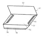
このような従来の往復式封筒による郵送方法の不便さを解決するため、本願出願人が開発して特願2002−035749により開示されたものが図9に示されている。この発明は封筒として出願されているが、送信用の封筒にミシン目を設けて開封するところに特徴を有するものである。すなわち、この封筒は封筒のフラップを大きく形成しこのフラップに1本以上のミシン目若しくは切り取り線を入れるとともに大きく形成したフラップの裏面若しくはフラップに対応する封筒本体に返信用宛名を印刷し、その宛名をフラップで覆い水糊などの糊を塗布し封止して送信する封筒で封止されたフラップの1本以上のミシン目若しくは切り取り線を切り離して返信用宛名を露出させて返信用封筒を形成することを特徴とする封筒である。また、その具体的な構成は送返信用封筒本体91の表側92と裏側93とが袖部94とフラップ95とで構成されている。このように構成された封筒を使用する場合は、初めに発送する通常の使用状態では左右の袖部94を折り曲げその上に裏側93を折り返して封筒を形成し、ついで表側92に宛名を書いて通信文書などを入れてからフラップ95を折って封をする。また、表側92の裏面には返信先の宛名を印刷するとともにフラップ95の先端近くにミシン目を設けかつ袖部94の先端にミシン目96を設け、更にミシン目96の先端側にミシン目96平行に水糊などの糊97を塗布して乾燥させる。更に、返送する場合は各ミシン目96を切り離して封筒を一枚のシート状に開き、通常状態で裏側93を表側92として裏返し袖部94を裏側93に折り返した上から裏側93を折り返し、更に袖部94と裏側93とを当接して袖部94の糊97で裏側93に接着させて返信用の封筒を作成する。
【0004】
【発明が解決しようとする課題】
このような従来方法による往復式による封筒を使用する郵送方法では、返信封筒を作成するのに手間がかかりすぎて実用化を図るうえで多く問題があり、これらの問題点を解決するところに本発明が解決しようとする課題を有する。
【0005】
【課題を解決するための手段】
本発明は上記の如き問題を解決するために改良したものであって、封筒の中に入れたアンケートの回答用紙やダイレクトメールで返事などを求める通知文を送信しかつ返信する郵送方法において、前記送信用封筒の上端開封部を完全に切り取らずに開封して通知文を封筒の中から取り出し、該送信用封筒を返信用の封筒として再利用すること特徴とする送返信兼備の往復式郵送方法の提供にあり、また前記の往復式郵送方法において往復式封筒本体の上端面又は側端面の裏側に開封部を設け該開封部に指先を差し込み左右に移動させてフラップ部分から裏側を剥がして開封しかつ前記フラップ部分を広げて裏側の上面に帖着してなる送返信兼備の往復式郵送方法の提供にあり、また前記の往復式郵送方法において往復式封筒本体の上端面又は側端面の裏側に開封部を設け、該開封部のフラップ部分を剥し取りかつ該フラップ部分を内側に折り込み裏側を帖着してなる送返信兼備の往復式郵送方法の提供にあり、また前記の往復式郵送方法において往復式封筒本体の素材に透明材を用いかつ表側にフラップ部分を設けて裏側に帖着し該フラップ部分を開封時に開封しかつフラップ部分を切断し裏側に帖着してなる送返信兼備の往復式郵送方法の提供にある。
【0006】
また本発明は、送信用と返信用とを兼ね備えた往復式郵送用の封筒において、前記封筒裏側の上端に指先で開封可能な半円形状の開封部を形成しかつ封筒の裏側が上面になるようにフラップ部分の上面に糊付けしてなる往復式封筒本体を設け、該封筒本体の開口部を指先を左右に移動させて開封しかつフラップ部分を糊り付けして返信することを特徴とする送返信兼備の往復式郵送用封筒の提供にあり、また前記の往復式郵送用封筒において前記封筒表側の上端に有するフラップ部分にミシン目を設けかつ封筒裏側の上端にフラップ部分を設けてなる送返信兼備の往復式郵送用封筒の提供にあり、また前記の往復式郵送用封筒において前記封筒本体を開封しかつ裏がえしにして糊付けてなる返信用の封筒にする送返信兼備の往復式郵送用封筒の提供にあり、また前記の往復式郵送用封筒において前記封筒本体の素材に透明材を用いかつ送信用の裏側上端面にフラップ部分を形成し更にフラップ部分を切り取り返信用の裏側をセパレーターにて帖り付けてなる送返信兼備の往復式郵送用封筒の提供にある。
【0007】
【発明の実施の形態】
本発明の実施形態は、封筒の中に入れたアンケートの回答用紙やダイレクトメールで返事などを求める通知文を送信しかつ返信する郵送方法において、前記送信用封筒の上端開封部を完全に切り取らずに開封して通知文を封筒の中から取り出し、該送信用封筒を返信用の封筒として再利用すること特徴とする送返信兼備の往復式郵送方法であり、また前記の往復式郵送方法において往復式封筒本体の上端面又は側端面の裏側に開封部を設け、該開封部に指先を差し込み左右に移動させてフラップ部分から裏側を剥がして開封しかつ前記フラップ部分を広げて裏側の上面に帖着してなるの送返信兼備の往復式郵送方法であり、また前記の往復式郵送方法において往復式封筒本体の上端面又は側端面の裏側に開封部を設け該開封部のフラップ部分を剥し取りかつ該フラップ部分を内側に折り込み裏側を帖着してなる送返信兼備の往復式郵送方法であり、また前記の往復式郵送方法において往復式封筒本体の素材に透明材を用いかつ表側にフラップ部分を設けて裏側に帖着し該フラップ部分を開封時に開封しかつフラップ部分を切断し裏側に帖着してなる送返信兼備の往復式郵送方法であるから、従来の往復式の封筒を用いて返信する方法よりも簡便で手軽な返信をすることが可能となる。
【0008】
また本発明の実施形態は、送信用と返信用とを兼ね備えた往復式郵送用の封筒において、前記封筒裏側の上端に指先で開封可能な半円形状の開封部を形成しかつ封筒の裏側が上面になるようにフラップ部分の上面に糊付けしてなる往復式封筒本体を設け、該封筒本体の開口部を指先を左右に移動させて開封しかつフラップ部分を糊付けして返信することを特徴とする送返信兼備の往復式郵送用封筒であり、また前記の往復式郵送用封筒において前記封筒表側の上端に有するフラップ部分にミシン目を設けかつ封筒裏側の上端にフラップ部分を設けてなる送返信兼備の往復式郵送用封筒であり、また前記の往復式郵送用封筒において前記封筒本体を開封しかつ裏がえしにして糊付けてなる返信用の封筒にする送返信兼備の往復式郵送用封筒であり、また前記の往復式郵送用封筒において前記封筒本体の素材に透明材を用いかつ送信用の裏側上端面にフラップ部分を形成し、更にフラップ部分を切り取り返信用の裏側をセパレーターにて帖り付けてなる送返信兼備の往復式郵送用封筒であるから、従来の往復式封筒よりも優れた返信用の封筒を簡単容易に作成することが可能となる。
【0009】
なお、本実施例では郵送用封筒について説明されているが、タックス紙などの送信用と返信用にも利用することも可能となる。
【0010】
【実施例】
以下、図面に従って本発明の送返信兼備の往復式郵送方法とその使用封筒の実施例について説明する。
【0011】
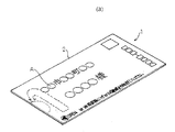
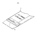
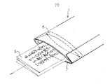
図1(a)から図1(c)は本発明の往復式郵送方法に使用される封筒を示したものであり、1はその往復式封筒本体である。この往復式封筒本体1は、送信宛名Aを表記する表側2と返信宛名Bを表記する裏側3とから構成されている。更に、裏側3の一端には開封部4が設けられている。このように構成されている往復式封筒本体1は、図1(c)で示しているように1枚の紙を中央から折り曲げ紙面に糊付部5を設けて糊付けされている。また裏側3の一端には、ミシン目7と脱着片6とを有するフラップ8が一体形成されている。
【0012】
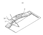
次に図2(a)から図2(f)により、本発明からなる往復式封筒の使用方法について説明する。まず、図1(a)から図1(c)に示す往復式封筒本体1の中に所望の書面Sを入れてフラップ8を内側に折り曲げて裏側3の線面を糊付けして送信する。その際、フラップ8の先端部は裏側3の内側に糊付けされる。ついで、送信先に往復式封筒本体1が着送されたならば裏側3の開封部4に有している半円形状の部分を手前に引き、そこに指先Rを差し込み左右に移動させるとフラップ8の脱着片6から裏側3が剥がれるので、この封筒部4から通知文などの書面Sを取り出す。ついで、取り出された書面Sの返信書面に所望文字を記入して返信する。返信する場合は、書面Sを入れた後にフラップ8の糊付けされていた脱着部6を切り剥し裏側3の上面をチューブ10入りの糊9を用いて糊付けして郵送する。すなわち、本発明からなる往復式の封筒はいちいち表側2と裏側3とを開封せずそのままの状態でフラップ8を外側に取り出して封印することが可能となるので、簡単容易に返信用の封筒を作成することができる。
【0013】
図3(a)から図(c)は本発明封筒の他の実施例を示したものであり、21は往復式封筒本体である。この往復式封筒本体21は、基本的な構成は図1に示した往復式封筒本体1と同じであるが、開封方法と封印方法が異なるものである。その相違点は、フラップ25に2ケ所のミシン目24を設けている点と送信用の裏側22に内側片23が設けられている点である。すなわち、送信用の裏側(図示せず)の先端部分にミシン目24入りのクラップ25を一体形成し、一方返信用の裏側22の先端部分にフラップ8よりも小さな内側片23が一体形成されている。このように構成されている往復式封筒本体21を用いて返信する場合は、返信用宛名Pが記入(返信用の文字)されている部分を残してミシン目24からクラップ25を切り剥がし、更にフラップ25全体のミシン目24からフラップ25を切り取り表側の先端に有する内側片23を表側にして糊付けして郵送する。なお、本実施例ではフラップ25を切り剥すのにミシン目を設けているが、ミシン目に限定されるものではなくいかなる手段でもよい。また、本実施例では原則として定形封筒を対象に説明されているが、上部又は下部が定型外の場合でも同一の作用と効果が得られる。
【0014】
図4(a)から図4(d)は本発明封筒の他の実施例を示したものであり、31は往復式封筒本体31である。この往復式封筒本体31も図1に示した往復式封筒本体1と基本的には同じ構成になっている。この往復式封筒本体31の特徴は、フラップ35に2本のミシン目34を入れ開封時にミシン目34間の脱着片36を両側に引きはがし、封印時にフラップ35を糊付ける方法である。なお、フラップ35に設けているミシン目34は前記同様に切り剥しが可能な方法であれば、いかなる手段でもよい。
【0015】
図5(a)から図5(c)と図6(a)から図6(b)は本発明封筒の他の実施例を示したものであり、基本的な構成と使用方法は前記図1(a)から図1(c)、図4(a)から図4(d)及び図5(a)から図5(c)に示したものと同じである。従って、詳細な説明は省略する。すなわち、往復式郵送用封筒において前記封筒表側の上端に有するフラップ部分にミシン目を設けかつ封筒裏側の上端にフラップ部分を設けてなる送返信兼備の往復式郵送用封筒の提供と、前記封筒本体を開封しかつ裏がえしにして糊り付けてなる返信用の封筒にする送返信兼備の往復式郵送用封筒を提供するものである。なお、詳細な説明は省略する。
【0016】
図7(a)から図7(e)は本発明封筒の他の実施例を示したものであり、基本的な構成とその使用方法は前記図1(a)から図1(c)、図4(a)から図4(d)及び図5(a)から図5(c)に示したものと同じであり、異るところは素材にビニールなどの透明材を使用した点である。すなわち、往復式郵送用封筒において、前記封筒本体の素材に透明材を用いかつ送信用の裏側上端面にフラップ部分を形成し、更にフラップ部分を切り取り返信用の裏側をセパレーターにて帖り付けてなる送返信兼備の往復式郵送用封筒を提供するものである。このような透明素材からなる封筒にすることによって、封筒に直接宛名を印刷する必要がないので同じ封筒を何回でも使用できるので経済的であるばかりか省エネにも役立つことになる。
【0017】
【発明の効果】
本発明は、封筒の中に入れたアンケートの回答用紙やダイレクトメールで返事などを求める通知文を送信しかつ返信する郵送方法において、前記送信用封筒の上端開封部を完全に切り取らずに開封して通知文を封筒の中から取り出し、該送信用封筒を返信用の封筒として再利用すること特徴とする送返信兼備の往復式郵送方法であり、また前記の往復式郵送方法において往復式封筒本体の上端面又は側端面の裏側に開封部を設け該開封部に指先を差し込み左右に移動させてフラップ部分から裏側を剥がして開封しかつ前記フラップ部分を広げて裏側の上面に帖着してなる送返信兼備の往復式郵送方法であり、また前記の往復式郵送方法において往復式封筒本体の上端面又は側端面の裏側に開封部を設け該開封部のフラップ部分を剥し取りかつ該フラップ部分を内側に折り込み裏側を帖着してなる送返信兼備の往復式郵送方法であり、また前記の往復式郵送方法において往復式封筒本体の素材に透明材を用いかつ表側にフラップ部分を設けて裏側に帖着し該フラップ部分を開封時に開封しかつフラップ部分を切断し裏側に帖着してなる送返信兼備の往復式郵送方法である。
【0018】
また本発明は、送信用と返信用とを兼ね備えた往復式郵送用の封筒において、前記封筒裏側の上端に指先で開封可能な半円形状の開封部を形成しかつ封筒の裏側が上面になるようにフラップ部分の上面に糊付けしてなる往復式封筒本体を設け、該封筒本体の開口部を指先を左右に移動させて開封しかつフラップ部分を糊付けして返信することを特徴とする送返信兼備の往復式郵送用封筒であり、また前記の往復式郵送用封筒において前記封筒表側の上端に有するフラップ部分にミシン目を設けかつ封筒裏側の上端にフラップ部分を設けてなる送返信兼備の往復式郵送用封筒であり、また前記の往復式郵送用封筒において前記封筒本体を開封しかつ裏がえしにして糊付けてなる返信用の封筒にするの送返信兼備の往復式郵送用封筒であり、また前記の往復式郵送用封筒において前記封筒本体の素材に透明材を用いかつ送信用の裏側上端面にフラップ部分を形成し更にフラップ部分を切り取り返信用の裏側をセパレーターにて帖り付けてなる送返信兼備の往復式郵送用封筒であるから、従来の往復式郵送方法とその使用封筒では得られない次のような多くの効果を有する。
ア、本発明からなる往復式の封筒を用いて送信と返信の郵送をすれば、簡単容易にしかも多くの手間ひまもかからずに送信用の封筒で返信することができる。
イ、また本発明の封筒を使用すれば、アンケートやダイレクトメールなどによる回答率や返信率を高めることができるので営業的に有効な郵送方法といえる。
ウ、また本発明の封筒を使用することによって、送信用の封筒をそのまま返信用の封筒として利用することができるので、廃棄ゴミによる環境問題に役立つばかりか省エネ問題にも大いに役立つことになる。
エ、また本発明の封筒はいたって構造が簡単であるから、低コストで大量生産が可能となるので経済性や実用性にも富んでいるといえる。
オ、更に本発明による封筒を用いて往復用として郵送をすれば、1通の封筒で返信用の郵便情報などを送信時には目に見えない方法で送信することができるとともに目に見える方法で送信と返信することができる。
【図面の簡単な説明】
【図1(a)】本発明の往復式封筒を示した説明概要図。
【図1(b)】本発明の往復式封筒を示した説明概要図。
【図1(c)】本発明の往復式封筒を示した説明概要図。
【図2(a)】図1(a)に示した本発明封筒の使用方法を示した説明概要図。
【図2(b)】図1(a)に示した本発明封筒の使用方法を示した説明概要図。
【図2(c)】図1(a)に示した本発明封筒の使用方法を示した説明概要図。
【図2(d)】図1(a)に示した本発明封筒の使用方法を示した説明概要図。
【図2(e)】図1(a)に示した本発明封筒の使用方法を示した説明概要図。
【図2(f)】図1(a)に示した本発明封筒の使用方法を示した説明概要図。
【図3(a)】本発明の他の実施例を示した説明概要図。
【図3(b)】本発明の他の実施例を示した説明概要図。
【図3(c)】本発明の他の実施例を示した説明概要図。
【図4(a)】本発明の他の実施例を示した説明概要図。
【図4(b)】本発明の他の実施例を示した説明概要図。
【図4(c)】本発明の他の実施例を示した説明概要図。
【図4(d)】本発明の他の実施例を示した説明概要図。
【図5(a)】本発明の他の実施例を示した説明概要図。
【図5(b)】本発明の他の実施例を示した説明概要図。
【図5(c)】本発明の他の実施例を示した説明概要図。
【図6(a)】本発明の他の実施例を示した説明概要図。
【図6(b)】本発明の他の実施例を示した説明概要図。
【図7(a)】本発明の他の実施例を示した説明概要図。
【図7(b)】本発明の他の実施例を示した説明概要図。
【図7(c)】本発明の他の実施例を示した説明概要図。
【図7(d)】本発明の他の実施例を示した説明概要図。
【図7(e)】本発明の他の実施例を示した説明概要図。
【図8(a)】従来の往復用ハガキと往復用封筒を示した説明概要図。
【図8(b)】従来の往復用ハガキと往復用封筒を示した説明概要図。
【図9】従来の往復式封筒を示した説明概要図。
【符号の説明】
1、21、31、41、51、61、91 往復式封筒本体
2、52、92 表側
3、22、32、42、54、62、93 裏側
4、26、63、66 開封部 5 糊付部
6、26、45 脱着片
7、24、34、44、96 ミシン目
8、25、35、95 フラップ
9、37、43、53、55、65、97 糊
10、38、56 チューブ 23 内側片
64 セパレーター 71 往復用ハガキ本体
72 送信ハガキ 73 送信ハガキ
81 返信用封筒本体 94 袖部
A 送信宛名 B 返信宛名 S 書面
R 指先 K ハサミ[0001]
TECHNICAL FIELD OF THE INVENTION
BACKGROUND OF THE INVENTION 1. Field of the Invention The present invention relates to a reciprocating mailing method and an envelope used for the same. More particularly, the present invention relates to a reciprocating mailing method capable of reusing a transmission envelope as a reply envelope and an envelope used for the method.
[0002]
[Prior art]
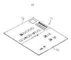
Conventionally commonly used reciprocating postcards and reciprocating envelopes include, for example, those shown in FIGS. 8A to 8B. In the case of a reciprocating postcard, a reciprocating postcard
[0003]
In order to solve the inconvenience of the conventional mailing method using a reciprocating envelope, FIG. 9 shows the one developed by the present applicant and disclosed in Japanese Patent Application No. 2002-035749. Although the present invention has been filed as an envelope, the present invention is characterized in that a transmitting envelope is provided with perforations and opened. That is, this envelope is formed with a large flap of the envelope, one or more perforations or cut lines are formed in the flap, and a reply address is printed on the back of the large flap or on the envelope body corresponding to the flap. Cover with a flap, apply glue such as water glue, seal it, and send it. One or more perforations or cut lines of the flap sealed with the envelope are cut off to expose the reply address and form a reply envelope. It is an envelope characterized by doing. Further, the specific configuration thereof is such that the
[0004]
[Problems to be solved by the invention]
Such a conventional mailing method using a reciprocating envelope requires a lot of trouble to create a reply envelope and has many problems in practical use. There is a problem to be solved by the invention.
[0005]
[Means for Solving the Problems]
The present invention has been improved in order to solve the above-described problems, and in a mailing method of transmitting and replying to a questionnaire response sheet or a direct mail requesting a reply by a direct mail in an envelope, A reciprocating mailing method for both sending and receiving, characterized in that the sending envelope is opened without completely cutting off the upper opening portion of the sending envelope, the notice is taken out of the envelope, and the sending envelope is reused as a reply envelope. In the reciprocating mailing method, an opening portion is provided on the back side of the upper end surface or the side end surface of the reciprocating envelope body, a fingertip is inserted into the opening portion, moved to the right and left, and the back side is peeled from the flap portion and opened. The present invention is to provide a reciprocating mailing method for both sending and receiving, wherein the flap portion is spread and attached to the upper surface of the back side, and in the reciprocating mailing method, the upper end surface of the reciprocating envelope body or An opening portion is provided on the back side of the end surface, a flap portion of the opening portion is peeled off, the flap portion is folded inward, and a back and forth side is provided. In the postal mailing method, a transparent material is used for the material of the reciprocating envelope main body, a flap portion is provided on the front side, the back side is stuck, the flap portion is opened at the time of opening, and the flap portion is cut and stuck on the back side. The purpose is to provide a round-trip mailing method that can be used both for replying.
[0006]
The present invention also provides a reciprocating mailing envelope having both transmission and replying, wherein a semicircular opening portion that can be opened with a fingertip is formed at the upper end of the back side of the envelope, and the back side of the envelope is the upper surface. A reciprocating envelope body glued to the upper surface of the flap portion is provided, the opening of the envelope body is opened by moving the fingertip left and right, and the flap portion is glued and returned. The present invention provides a reciprocating mailing envelope for both sending and replying, and in the reciprocating mailing envelope, a flap portion is provided at a flap portion at the upper end on the front side of the envelope and a flap portion is provided at an upper end on the back side of the envelope. A reciprocating mailing envelope is provided for both replying and reciprocating mailing, and in the reciprocating mailing envelope, the envelope body is opened and turned over to form a reply envelope formed by gluing. Mailing envelope In the reciprocating mailing envelope, a transparent material is used for the material of the envelope body, and a flap portion is formed on the upper end surface on the back side for transmission, and the flap portion is further cut out and the back side for reply is separated by a separator. The purpose of the present invention is to provide a reciprocating mailing envelope that can be sent and returned.
[0007]
BEST MODE FOR CARRYING OUT THE INVENTION
The embodiment of the present invention is a mailing method for transmitting and replying to a questionnaire answer sheet or a direct mail requesting a reply by a direct mail put in an envelope, and does not completely cut off the upper end opening portion of the transmission envelope. , The notification message is taken out of the envelope, and the transmission envelope is reused as a reply envelope. An opening portion is provided on the back side of the upper end surface or the side end surface of the type envelope main body, a fingertip is inserted into the opening portion, moved to the left and right, the back side is peeled from the flap portion and opened, and the flap portion is spread and the tablet is spread on the upper surface on the back side. This is a reciprocating mailing method for both sending and receiving, and in the above-described reciprocating mailing method, an opening portion is provided on the back side of the upper end surface or the side end surface of the reciprocating envelope body, and a flap portion of the opening portion is provided. This is a reciprocating mailing method of peeling and folding the flap part inside and folding the back side, and in the reciprocating mailing method, a transparent material is used for the material of the reciprocating envelope body and the front side is used. It is a reciprocating mailing method that has a flap part and is attached to the back side, and the flap part is opened at the time of opening, and the flap part is cut and pledged on the back side. It is possible to make a simpler and easier reply than the method of replying by using.
[0008]
Further, an embodiment of the present invention provides a reciprocating mailing envelope having both sending and replying, wherein a semicircular opening portion that can be opened with a fingertip is formed at the upper end of the back side of the envelope and the back side of the envelope is formed. A reciprocating envelope body glued to the upper surface of the flap portion so as to be the upper surface is provided, the opening of the envelope body is opened by moving the fingertip to the left and right, and the flap portion is glued and returned. A reciprocating mailing envelope which is provided with a perforation at the upper end on the front side of the envelope and a flap at the upper end on the back side of the envelope in the reciprocating mailing envelope. A reciprocating mailing envelope which is a combined reciprocating mailing envelope, and a reciprocating mailing envelope which is a reply envelope formed by opening the envelope body, turning over and gluing the envelope body in the reciprocating mailing envelope. In Also, in the reciprocating mailing envelope, a transparent material is used as a material of the envelope body, and a flap portion is formed on the upper end surface on the back side for transmission, and the flap portion is further cut off and the back side for reply is marked with a separator. Since the envelope is a reciprocating mailing envelope that can be sent and returned, it is possible to easily and easily create a reply envelope that is superior to a conventional reciprocating envelope.
[0009]
In this embodiment, the mailing envelope is described. However, the mailing envelope can also be used for transmitting and replying to tax paper or the like.
[0010]
【Example】
An embodiment of a reciprocating mailing method for both sending and receiving and an envelope used in the present invention will be described below with reference to the drawings.
[0011]
1 (a) to 1 (c) show an envelope used in the reciprocating mailing method of the present invention, and 1 is the reciprocating envelope main body. The reciprocating envelope main body 1 is composed of a front side 2 on which a transmission address A is indicated and a back side 3 on which a reply address B is indicated. Further, an
[0012]
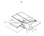
Next, a method of using the reciprocating envelope according to the present invention will be described with reference to FIGS. First, a desired document S is inserted into the reciprocating envelope main body 1 shown in FIGS. 1A to 1C, the
[0013]
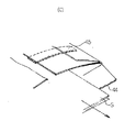
3 (a) to 3 (c) show another embodiment of the envelope of the present invention, wherein 21 is a reciprocating envelope main body. The reciprocating envelope
[0014]
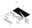
FIGS. 4 (a) to 4 (d) show another embodiment of the envelope of the present invention, wherein 31 is a reciprocating envelope
[0015]
FIGS. 5 (a) to 5 (c) and FIGS. 6 (a) to 6 (b) show another embodiment of the envelope of the present invention. These are the same as those shown from (a) to FIG. 1 (c), FIGS. 4 (a) to 4 (d), and FIGS. 5 (a) to 5 (c). Therefore, detailed description is omitted. That is, in a reciprocating mailing envelope, providing a reciprocating mailing envelope which is provided with a perforation at a flap portion at the upper end on the front side of the envelope and a flap portion at an upper end on the back side of the envelope, and the envelope body The present invention is to provide a reciprocating mailing envelope which can be used as a reply envelope which is opened and turned over to form a reply envelope formed by gluing. Detailed description is omitted.
[0016]
FIGS. 7 (a) to 7 (e) show another embodiment of the envelope of the present invention. The basic structure and the method of using the same are shown in FIGS. 1 (a) to 1 (c) and FIG. 4 (a) to 4 (d) and FIGS. 5 (a) to 5 (c). The difference is that a transparent material such as vinyl is used as the material. That is, in the reciprocating mail envelope, a transparent material is used as the material of the envelope body, and a flap portion is formed on the upper end surface on the back side for transmission, the flap portion is further cut off, and the back side for reply is marked with a separator. The present invention provides a reciprocating mailing envelope which can be sent and received. By using such an envelope made of a transparent material, it is not necessary to print the address directly on the envelope, and the same envelope can be used any number of times.
[0017]
【The invention's effect】
The present invention relates to a mailing method for transmitting and replying to a questionnaire answer sheet or a direct mail requesting a reply by a direct mail placed in an envelope, and opening the upper end opening portion of the transmission envelope without completely cutting it off. A reciprocating mailing method, which is characterized by retrieving the notification message from the envelope and reusing the sending envelope as a reply envelope. An opening portion is provided on the back side of the upper end surface or the side end surface, a fingertip is inserted into the opening portion, moved to the right and left, the back side is peeled off from the flap portion and opened, and the flap portion is spread and stuck on the upper surface of the back side. It is a reciprocating mailing method that is both sending and replying, and in the above-mentioned reciprocating mailing method, an opening portion is provided on the back side of the upper end surface or the side end surface of the reciprocating envelope body, and the flap portion of the opening portion is peeled off and This is a reciprocating mailing method that has a flap part folded inward and a back side attached to it. This is a reciprocating mailing method in which the flap portion is opened at the time of opening, the flap portion is opened at the time of opening, the flap portion is cut, and the flap portion is attached to the back side.
[0018]
The present invention also provides a reciprocating mailing envelope having both transmission and replying, wherein a semicircular opening portion that can be opened with a fingertip is formed at the upper end of the back side of the envelope, and the back side of the envelope is the upper surface. A reciprocating envelope body glued on the upper surface of the flap portion, opening the envelope body by moving the fingertip to the left and right, opening the flap portion and gluing the flap portion for reply. It is a reciprocating mailing envelope which is a combined reciprocating mailing machine.In the reciprocating mailing envelope, a flap portion is provided at an upper end of the front side of the envelope and a flap portion is provided at an upper end of the back side of the envelope. It is a reciprocating mailing envelope which is a reciprocating mailing envelope, wherein the envelope body is opened in the reciprocating mailing envelope and the envelope is turned upside down to form a reply envelope. ,Also In the reciprocating mailing envelope described above, a transparent material is used for the material of the envelope body, a flap portion is formed on the upper end surface on the back side for transmission, the flap portion is further cut out, and the back side for reply is cut with a separator. Since it is a reciprocating mailing envelope that can be used both in reply, it has a number of effects that cannot be obtained by the conventional reciprocating mailing method and the envelope used therefor.
A. If the sending and replying mails are sent using the reciprocating envelope according to the present invention, the reply can be made easily and easily with a sending envelope without much trouble.
A. If the envelope of the present invention is used, a response rate and a reply rate by a questionnaire and direct mail can be increased, so that it can be said that the mailing method is commercially effective.
C. Also, by using the envelope of the present invention, the envelope for transmission can be used as it is as the envelope for reply, so that it is very useful not only for environmental problems due to discarded garbage but also for energy saving problems.
D) Further, since the envelope of the present invention has a very simple structure, it can be mass-produced at low cost, so that it can be said that it is rich in economy and practicality.
E. Further, if mail is sent back and forth using the envelope according to the present invention, postal information for reply can be transmitted in an invisible manner at the time of transmission and transmitted in a visible manner with one envelope. You can reply.
[Brief description of the drawings]
FIG. 1A is an explanatory schematic diagram showing a reciprocating envelope of the present invention.
FIG. 1 (b) is an explanatory schematic diagram showing a reciprocating envelope of the present invention.
FIG. 1C is an explanatory schematic diagram showing a reciprocating envelope of the present invention.
FIG. 2A is an explanatory schematic diagram showing a method of using the envelope of the present invention shown in FIG. 1A.
FIG. 2 (b) is an explanatory schematic diagram showing a method of using the envelope of the present invention shown in FIG. 1 (a).
FIG. 2 (c) is an explanatory schematic diagram showing a method of using the envelope of the present invention shown in FIG. 1 (a).
FIG. 2 (d) is an explanatory schematic view showing a method of using the envelope of the present invention shown in FIG. 1 (a).
FIG. 2 (e) is an explanatory schematic diagram showing a method of using the envelope of the present invention shown in FIG. 1 (a).
FIG. 2 (f) is an explanatory schematic diagram showing a method of using the envelope of the present invention shown in FIG. 1 (a).
FIG. 3A is an explanatory schematic diagram showing another embodiment of the present invention.
FIG. 3 (b) is an explanatory schematic diagram showing another embodiment of the present invention.
FIG. 3C is an explanatory schematic diagram showing another embodiment of the present invention.
FIG. 4A is an explanatory schematic diagram showing another embodiment of the present invention.
FIG. 4 (b) is an explanatory schematic diagram showing another embodiment of the present invention.
FIG. 4 (c) is an explanatory schematic diagram showing another embodiment of the present invention.
FIG. 4D is an explanatory schematic diagram showing another embodiment of the present invention.
FIG. 5A is an explanatory schematic diagram showing another embodiment of the present invention.
FIG. 5B is an explanatory schematic diagram showing another embodiment of the present invention.
FIG. 5 (c) is an explanatory schematic diagram showing another embodiment of the present invention.
FIG. 6A is an explanatory schematic diagram showing another embodiment of the present invention.
FIG. 6B is an explanatory schematic diagram showing another embodiment of the present invention.
FIG. 7A is an explanatory schematic diagram showing another embodiment of the present invention.
FIG. 7 (b) is an explanatory schematic diagram showing another embodiment of the present invention.
FIG. 7C is an explanatory diagram showing another embodiment of the present invention.
FIG. 7D is an explanatory schematic diagram showing another embodiment of the present invention.
FIG. 7 (e) is an explanatory schematic diagram showing another embodiment of the present invention.
FIG. 8A is an explanatory schematic diagram showing a conventional reciprocating postcard and reciprocating envelope.
FIG. 8B is an explanatory schematic diagram showing a conventional reciprocating postcard and reciprocating envelope.
FIG. 9 is an explanatory schematic diagram showing a conventional reciprocating envelope.
[Explanation of symbols]
1, 21, 31, 41, 51, 61, 91 Reciprocating envelope
Claims (8)
Priority Applications (1)
| Application Number | Priority Date | Filing Date | Title |
|---|---|---|---|
| JP2003172942A JP2004091048A (en) | 2002-07-11 | 2003-06-18 | Double postal service of both sending and reply, and envelope therefor |
Applications Claiming Priority (2)
| Application Number | Priority Date | Filing Date | Title |
|---|---|---|---|
| JP2002236708 | 2002-07-11 | ||
| JP2003172942A JP2004091048A (en) | 2002-07-11 | 2003-06-18 | Double postal service of both sending and reply, and envelope therefor |
Related Child Applications (1)
| Application Number | Title | Priority Date | Filing Date |
|---|---|---|---|
| JP2008008092U Continuation JP3148114U (en) | 2002-07-11 | 2008-11-18 | Reciprocating envelope |
Publications (2)
| Publication Number | Publication Date |
|---|---|
| JP2004091048A true JP2004091048A (en) | 2004-03-25 |
| JP2004091048A5 JP2004091048A5 (en) | 2008-06-26 |
Family
ID=32072410
Family Applications (1)
| Application Number | Title | Priority Date | Filing Date |
|---|---|---|---|
| JP2003172942A Pending JP2004091048A (en) | 2002-07-11 | 2003-06-18 | Double postal service of both sending and reply, and envelope therefor |
Country Status (1)
| Country | Link |
|---|---|
| JP (1) | JP2004091048A (en) |
-
2003
- 2003-06-18 JP JP2003172942A patent/JP2004091048A/en active Pending
Similar Documents
| Publication | Publication Date | Title |
|---|---|---|
| JP2004091048A (en) | Double postal service of both sending and reply, and envelope therefor | |
| JP3148114U (en) | Reciprocating envelope | |
| JPH11286192A (en) | Two-way postcard | |
| JP3058770U (en) | Round-trip mail envelope | |
| JP2008013190A (en) | Sending/returning mail method, and envelope used for the same | |
| JP3075623U (en) | Sticky paper for envelopes. | |
| JPH07277344A (en) | Envelope containing book | |
| JP2003291980A (en) | Envelope | |
| KR200347338Y1 (en) | Envelope | |
| JP3014640U (en) | Foldable envelope | |
| JP3023649U (en) | Direct mail envelope | |
| RU31566U1 (en) | Multifunctional return envelope booklet (options) | |
| KR200332815Y1 (en) | Printing envelope | |
| JPH08300856A (en) | Foldable postcard | |
| JP3146123U (en) | Reciprocating envelope | |
| WO2003051728A1 (en) | Envelope | |
| JP2957635B2 (en) | Email forms and how to use them | |
| JP4362819B2 (en) | Sealed form sheet | |
| KR200365998Y1 (en) | Letter envelope paper for combination and seal | |
| JPH09207945A (en) | Envelope sheet | |
| JPH07329459A (en) | Special envelop letter | |
| JP3000981U (en) | Folded envelope for distribution | |
| KR200178285Y1 (en) | a letter paper combined use an envelop | |
| JPH07329458A (en) | Special envelop letter | |
| JPH10218195A (en) | Envelope |
Legal Events
| Date | Code | Title | Description |
|---|---|---|---|
| A621 | Written request for application examination |
Free format text: JAPANESE INTERMEDIATE CODE: A621 Effective date: 20060525 |
|
| A521 | Written amendment |
Free format text: JAPANESE INTERMEDIATE CODE: A523 Effective date: 20060630 |
|
| A521 | Written amendment |
Effective date: 20060630 Free format text: JAPANESE INTERMEDIATE CODE: A821 |
|
| A521 | Written amendment |
Effective date: 20060823 Free format text: JAPANESE INTERMEDIATE CODE: A523 |
|
| A521 | Written amendment |
Effective date: 20080508 Free format text: JAPANESE INTERMEDIATE CODE: A523 |
|
| RD02 | Notification of acceptance of power of attorney |
Free format text: JAPANESE INTERMEDIATE CODE: A7422 Effective date: 20080508 |
|
| A131 | Notification of reasons for refusal |
Free format text: JAPANESE INTERMEDIATE CODE: A131 Effective date: 20080917 |
|
| A521 | Written amendment |
Free format text: JAPANESE INTERMEDIATE CODE: A523 Effective date: 20081117 |
