JP2004090414A - Liquid storing cartridge and ink cartridge - Google Patents
Liquid storing cartridge and ink cartridge Download PDFInfo
- Publication number
- JP2004090414A JP2004090414A JP2002254653A JP2002254653A JP2004090414A JP 2004090414 A JP2004090414 A JP 2004090414A JP 2002254653 A JP2002254653 A JP 2002254653A JP 2002254653 A JP2002254653 A JP 2002254653A JP 2004090414 A JP2004090414 A JP 2004090414A
- Authority
- JP
- Japan
- Prior art keywords
- liquid
- flow path
- cartridge
- ink
- liquid storage
- Prior art date
- Legal status (The legal status is an assumption and is not a legal conclusion. Google has not performed a legal analysis and makes no representation as to the accuracy of the status listed.)
- Pending
Links
Images


Abstract
Description
【0001】
【発明の属する技術分野】
本発明は、液体収容カートリッジに関し、詳細には、例えば記録媒体へ向けてインクを噴射して記録を行う記録ヘッドをはじめ、液晶ディスプレー等のカラーフィルタ製造に用いる色材噴射ヘッド、有機ELディスプレーやFED(面発光ディスプレー)等の電極形成に用いられる電極材(導電ペースト)噴射ヘッド、バイオチップ製造に用いられる生体有機物噴射ヘッド、精密ピペットとしての試料噴射ヘッド等として利用可能な液体噴射ヘッドを備えた液体噴射装置に着脱可能に装着され、前記液体噴射ヘッドに液体を供給する液体収容カートリッジに関する。
【0002】
【従来の技術】
液体噴射装置の代表的存在として知られるインクジェット式記録装置においては、インク供給手段として、着脱自在な交換式カートリッジにインクを収容したインクカートリッジ方式が多用されている。このインクカートリッジ方式のインクジェット式記録装置は、通例、主走査方向に往復移動するキャリッジに搭載された記録ヘッドと、印刷用紙等の記録媒体を副走査方向に間欠的に設定量ずつ送る記録媒体送り手段を備え、キャリッジには、例えばブラック、シアン、マゼンタ、イエローなど複数の異なる色のインクカートリッジを装着できるようになっている。そして、記録ヘッドを主走査方向に移動させつつ、公知のように記録ヘッド内の圧力発生室でインクを所定圧で加圧し、その圧力に基づいてインクをノズル形成面にあるノズル開口から記録媒体に向けてコントロールされた大きさのインク滴として吐出して記録を行うように構成されている。
【0003】
インクジェット式記録装置においてインク供給手段となるインクカートリッジは、通常、記録ヘッドに連結可能に形成されたインク供給口と、インクを収容する一ないし複数のインク収容室と、インク収容室から前記インク供給口に至るインク流路と、を備えた構造をしている。そして近年では、高精度の記録を行わせるために、内部の圧力を調整して最適な量のインクを供給する等の要請から、インクカートリッジ内部の流路構造は非常に複雑なものになっている。その結果、必然的にインクカートリッジにおける圧力損失は大きなものとなり、同じインクカートリッジをノズル数の異なる記録ヘッドに用いると、ノズル数の多い記録ヘッド(例えば360ノズル)ではインクカートリッジ内の圧力損失の影響を受け吐出インク量が少なくなり、ノズル数の少ない記録ヘッド(例えば60ノズル)では、吐出インク量が多くなってしまう傾向にある。従って、ノズル数の異なる記録ヘッドには、それぞれ適切な圧力損失となるように、異なる流路抵抗を持つインクカートリッジを個々に設計することが望ましい。
【0004】
しかし、記録ヘッドのノズル数に応じてインクカートリッジを設計するとした場合は、その分コストの上昇を招くほか、一つのインクカートリッジを使用できる機種の幅が狭くなってしまう。現在では使用済みのインクカートリッジを回収してリサイクルしているが、インクカートリッジの種類が多くなるほど、回収作業が複雑になって再利用が困難になる。従って、資源の有効利用の観点からもインクカートリッジは出来るだけ共通化することが望ましい。
【0005】
【発明が解決しようとする課題】
上記のように、インクジェット式記録装置に高精度の記録を行わせるためには、インクカートリッジに複雑な流路構造が必要となる一方で、できるだけ部品を共通化することが望まれている。また、インクジェット式記録装置以外の液体噴射装置、例えば精密ピペットとしての試料噴射ヘッド等において試薬をカートリッジ方式で供給する場合など、においても同様の課題が存在する。
【0006】
従って、液体収容カートリッジにおいて、液体噴射ヘッドへの適正な液体の供給性能を確保しつつ、異なる種類の液体噴射ヘッドに共通して利用することが可能な液体収容カートリッジを提供することが求められている。これが本発明の課題である。
【0007】
【課題を解決するための手段】
上記課題を解決するため、第1の態様に係る液体収容カートリッジの発明は、噴射ノズルから目的物に向けて液体を噴射する液体噴射ヘッドに連結可能に形成された液体供給口と、液体を収容する一ないし複数の液体収容室と、前記液体収容室から前記液体供給口に至る液体流路と、を備え、前記液体噴射ヘッドに液体を供給する液体収容カートリッジであって、前記液体流路の途中に、流路抵抗調整手段を設けたことを特徴とする。
供給側である液体収容カートリッジ内の圧力損失は、液体噴射ヘッドにおける液体の吐出速度や吐出量に影響を与えるが、流路抵抗調整手段により液体収容カートリッジの基本的な構造を大きく変えることなく圧力損失を調整して最適化することが可能になる。よって、液体収容カートリッジを装着する液体噴射ヘッドに応じた圧力損失の設定も容易に行えるようになり、良好な噴射特性を維持することが可能になる。
【0008】
第2の態様に係る液体収容カートリッジの発明は、第1の態様において、前記流路抵抗調整手段は、前記噴射ノズルの数に応じて液体収容カートリッジ内の流路抵抗を調整するものであることを特徴とする。
液体収容カートリッジ内の流路抵抗は、圧力損失に影響を及ぼす。具体的には、流路抵抗が大きくなれば、圧力損失も大きくなる。この供給側の圧力損失の影響は、同じ液体収容カートリッジを噴射ノズル数の異なる液体噴射ヘッドに使用した場合に吐出性能(吐出量、吐出速度)の差となって現れる。従って、噴射ノズル数が多い場合、あるいは少ない場合に応じて、液体収容カートリッジの流路抵抗を調整することによって、液体収容カートリッジの圧力損失を液体噴射ヘッドに見合った最適な状態に調整することができる。
【0009】
第3の態様に係る液体収容カートリッジの発明は、第2の態様において、前記液体流路を形成する壁の一部は取付けまたは取り外し可能な壁体により構成され、前記流路抵抗調整手段は、前記壁体が取付けられている状態の前記液体流路、または前記壁体が取り外されて壁の一部が欠損した状態の前記液体流路、により構成されるものであることを特徴とする。
この特徴によれば、液体流路を形成する壁の一部を取付けまたは取り外し可能にする、という簡易な構成により、液体収容カートリッジの流路抵抗が噴射ヘッドに応じた最適な状態に調整される。
【0010】
第4の態様に係る液体収容カートリッジの発明は、第2の態様において、前記流路抵抗調整手段は、前記液体流路の一部に設けられた、着脱可能にユニット化された流路であることを特徴とする。
この特徴によれば、着脱可能にユニット化された流路を装着する、という簡易な構成により、液体収容カートリッジの流路抵抗が噴射ヘッドに応じた最適な状態に調整される。
【0011】
第5の態様に係る液体収容カートリッジの発明は、第2の態様において、前記流路抵抗調整手段は、前記液体流路の一部に設けられた流体抵抗部材であることを特徴とする。
この特徴によれば、流体抵抗部材を装着する、という簡易な構成により、液体収容カートリッジの流路抵抗が噴射ヘッドに応じた最適な状態に調整される。
【0012】
第6の態様に係る液体収容カートリッジの発明は、第1の態様から第5の態様のいずれかにおいて、前記液体収容カートリッジは、液体噴射装置に接続可能な記憶手段を備えており、前記流路抵抗調整手段により設定された流路抵抗情報が前記記憶手段に書き込まれていることを特徴とする。
この特徴によれば、記憶手段に書き込まれた流路抵抗情報により、その液体収容カートリッジの流路抵抗を知ることが可能になる。よって、液体噴射ヘッドのノズル数等に対応した流路抵抗を持つ液体収容カートリッジであるか否かを識別することができるようになり、液体収容カートリッジを用いる液体噴射ヘッドの噴射性能を最適な状態に維持できる。
【0013】
第7の態様に係る液体収容カートリッジの発明は、噴射ノズルから目的物に向けて液体を噴射する液体噴射ヘッドに連結可能に形成された液体供給口と、液体を収容する一ないし複数の液体収容室と、前記液体収容室から前記液体供給口に至る液体流路と、を備え、前記液体噴射ヘッドに液体を供給する液体収容カートリッジであって、該液体収容カートリッジは、前記液体流路を形成する壁の一部が着脱可能に構成された共通の基体から、前記噴射ノズルの数に応じて前記着脱可能な壁の一部または全部を取付けまたは取り外すことにより製造されてなることを特徴とする。また、第8の態様に係る液体収容カートリッジの発明は、噴射ノズルから目的物に向けて液体を噴射する液体噴射ヘッドに連結可能に形成された液体供給口と、液体を収容する一ないし複数の液体収容室と、前記液体収容室から前記液体供給口に至る液体流路と、を備え、前記液体噴射ヘッドに液体を供給する液体収容カートリッジであって、該液体収容カートリッジは、共通の基体から、前記噴射ノズルの数に応じて前記液体流路の一部にユニット化された流路を取付けることにより、製造されてなることを特徴とする。さらに、第9の態様に係る液体収容カートリッジの発明は、噴射ノズルから目的物に向けて液体を噴射する液体噴射ヘッドに連結可能に形成された液体供給口と、液体を収容する一ないし複数の液体収容室と、前記液体収容室から前記液体供給口に至る液体流路と、を備え、前記液体噴射ヘッドに液体を供給する液体収容カートリッジであって、該液体収容カートリッジは、共通の基体から、前記噴射ノズルの数に応じて前記液体流路の一部に流体抵抗部材を取付けることにより、製造されてなることを特徴とする。
上記第7から第9の態様では、異なる流体抵抗を持つカートリッジが、共通の基体から製造される。従って、液体噴射ヘッドのノズル数に応じて流路抵抗の最適化を図りつつ、基礎部品の共通化、およびこれに伴う低コスト化が可能になり、リサイクル利用も容易になる。
【0014】
本発明の第10の態様は、第1の態様から第9の態様のいずれかに記載の液体収容カートリッジは、前記液体として着色剤を含有するインク組成物を収容した、インクカートリッジであることを特徴とする。
この特徴によれば、インクカートリッジにおいて、第1の態様から第9の態様のいずれかと同様の作用効果が得られるので、インクカートリッジの流路抵抗を、液体噴射ヘッド(記録ヘッド)との関係において最適なものにすることが可能になり、高い精度での記録が可能になる。
【0015】
【発明の実施の形態】
以下、図面に基づき本発明の実施の形態を説明する。図1、図2は、本発明の液体噴射収容カートリッジの一実施形態に係るインクカートリッジ101の外観を示す斜視図であり、図3、図4は同分解斜視図である。このインクカートリッジ101は、液体噴射装置としてのインクジェット式記録装置に使用されるものである。インクカートリッジ101は、一方の面が開口した扁平な矩形状の有底箱型の容器本体102と、この開口を封止する蓋体103とを主体として構成されている。挿入方向の先端側、この実施例では底面の、長手方向の一方に偏するようにインク供給口104が形成されている。
【0016】
インクカートリッジ101の挿抜時に前方、及び後方となるそれぞれの壁の上部にはそれぞれ係止部材105、106が容器本体102と一体に形成されている。インク供給口側に偏して位置する係止部材105は、挿入方向の先端側、この実施例では下端より若干上部を回動支点とし、かつ上部が外側に拡開可能に形成されている。また、対向する他方の係止部材106は、係止部材105と協働してインクカートリッジ101の把持を補助するように形成されている。これら係止部材105、106は、その側面が幅方向の位置を規制するガイド部材となるように、キャリッジ200に設けられた挿入口の幅に対応する幅として構成されている。
【0017】
また、インク供給口側の係止部材105の下部には、基板の表面に電極107aが2列、上下方向に形成され、基板の裏面に電極107aに接続された半導体記憶素子を備えた記憶手段107が設けられ、他方の係止部材106の下部にはバルブ収容室108が形成されている。
【0018】
インク供給口104の近傍で、かつ容器の中央領域側にはインクカートリッジ101の挿抜方向に延び、かつ少なくとも先端側が開口したスリット部109が形成されている。このスリット部109は、少なくともインク供給口104の先端がキャリッジ200のインク供給針202(図14)に到達する以前にインク供給口104の開口面がインク供給針202に対して直交するように規制できる長さ、及び幅となるように構成されている。
【0019】
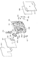
図5、図6は、インクカートリッジ101を構成する容器本体102に形成された流路の一実施例を示すものであって、容器本体102は、略水平方向に延びる壁110により上下に分割されている。容器本体102には、インクカートリッジ101においてインクを収容する部屋となる第1インク収容室111、第2インク収容室116、第3インク収容室117、および第4インク収容室123が形成されている。
【0020】
第1インク収容室111は下部領域に設けられている。また上部は、壁110を底面として、容器本体102の壁112と一定の間隙を持たせて大気連通路113を形成するように、壁110と連続する枠部114により区画されている。枠部114は、底部に連通口115aが形成された垂直な壁115により分割され、一方の領域は第2インク収容室116を、また他方の領域は第3インク収容室117を形成している。
【0021】
第2インク収容室116の下方の第1インク収容室111の領域には、第2インク収容室116の底面と容器本体102の底面102aとを接続する吸い上げ流路118が形成されている。なお、この実施例では吸い上げ流路118は、容器本体102の表面に凹部118c(図7)を形成し、この凹部118cを遮気性のフィルム157により封止することにより構成されている。
【0022】
吸い上げ流路118の下部に連通口119a、119bを備えた壁119が形成され、また吸い上げ流路118の一端に対向する箇所には容器本体102に外部からインクの注入のための1つの開口120が、またこれと並ぶように第1インク収容室111に連通する他の開口121が形成されている。
【0023】
第3インク収容室117は、枠部114の上面114aと一定の間隙を隔てて壁122、124、126により、また第4インク収容室123は壁110、124、126、127により区画されている。また、差圧弁収容室133(図7)の裏面に連通する流路が、壁124により区画されている。
【0024】
壁124の下部には壁110との間に連通口126aを備えた区画壁126が形成されている。枠部114との間には下部に連通口127aを備えた区画壁127を設けてインク流路128が形成されている。また、第4インク収容室123の領域において、連通口127aに連なる直前の部分には蛇行した抵抗調整用流路10(後述)が形成されている。インク流路128の上部は、フィルタ室となる貫通穴129を介してインクカートリッジ101の表面側に連通している。この貫通孔129には多孔質材からなるフィルタ155(図3)が挿入されている。なお、図中符号102cは、記憶手段107を収容する凹部を示す。
【0025】
貫通穴129は、図6に示すように壁127と連続して形成された壁130により分離され凹部129aによりインク流路128の上端に連通し、容器本体102の表面側の水滴形の凹部130a(図7)を介して差圧弁収容室133の裏面の壁134、及び壁124で区画された流路の上部の凹部124aに連通されている。
【0026】
差圧弁収容室133の下部とインク供給口104とは、容器本体102の表面に形成された凹部135と、この凹部135を覆う遮気性フィルム157(図8)とからなる流路により接続されている。
【0027】
また、図7に示すように、容器本体102の表面には、可及的に流路抵抗が高くなるように蛇行する細溝136と、これの周囲に幅広の溝137と、第2インク収容室116に対向する領域に矩形状の凹部138が形成されている。矩形状の凹部138にはさらに一段下がった位置に枠部139とリブ140が形成され、これらに撥インク性と通気性とを備えた図示しない通気性フィルムを張設して大気通気室が区画形成されている。凹部138の底面には貫通穴141が形成され、第2インク収容室116の壁142で区画された細長い領域143(図5)に連通されている。また凹部138の、通気性フィルムよりも表面側の領域で細溝136が連通されている。領域143の他端は連通用の溝145を介してバルブ収容室108に連通されている。
【0028】
バルブ収容室108の、インクカートリッジ101挿入側の先端、この実施例では図6に示したように下部に窓108aが形成されて開放されていて、記録装置本体のキャリッジ200に設けられた複数の識別片及びバルブ作動杆が進入可能な識別ブロック170(図3、図4)が装着されている。
【0029】
図8は、差圧弁収容室133の近傍の断面構造を示すものであって、差圧弁収容室133には、バネ150と、エラストマー等の弾性変形可能な材料により構成され、中心に貫通穴151を備えた膜弁152が収容されている。膜弁152はその周囲を環状の厚肉部152aと、この厚肉部152aと一体的に形成された枠部154とを備え、この枠部154を介して容器本体102に固定され、またバネ150は、一端を膜弁152のバネ受け部152bに、他端を収容室133の開口に嵌装される蓋体153のバネ受け部153aに支持されている。
【0030】
なお、符号156、157は、容器本体102の表面、及び開口面側に貼付された遮気性フィルムで、フィルム156は、図5における壁110、枠部114、壁115、122、124、126、127、130、及び142に溶着等により接着されている。またフイルム157は、容器本体102の表面に形成された細溝136、及び差圧弁収容室133を覆うように貼着されている。
【0031】
このような構成により、インク流通口134aを通過したインクは、膜弁152に阻止される。この状態でインク供給口104の圧力が低下すると、膜弁152がバネ150の付勢力に抗して弁座部134bから離れるため、インクは貫通穴151を通過し、凹部135により形成された流路を経由してインク供給口104に流れ込む。インク供給口104のインク圧力が所定の値に上昇すると、膜弁152がバネ150の付勢力に負けて弁座部134bに弾接され、インクの流通が遮断される。このような動作を繰返すことにより一定の負圧を維持しながらインクをインク供給口104に排出することができる。
【0032】
図9は、大気連通用のバルブ収容室108の断面構造を示すものであって、バルブ収容室108を区画する壁には貫通穴160が穿設され、ここにゴム等の弾性部材により構成された押圧部材161がその周囲を容器本体102に支持されて移動可能に挿入されている。押圧部材161の進入側の先端には、下端を突起163により固定され、中央部を突起164により規制された板バネなどの弾性部材162に支持され、貫通穴160に常時付勢された弁体165が配置されている。また押圧部材161の他面には識別ブロック170が位置するように装着されている。
【0033】
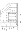
図10から図13は、インクカートリッジ101の内部の構造を拡大して示す図面である。本実施形態においては、第4インク収容室123の出口である連通口127aの直前に、流路抵抗調整手段として、壁110と、壁体31〜34と、壁体21〜27とにより区画される抵抗調整用流路10を備えている。なお、図11〜図13中、白抜きの矢印はインクの流れを意味する。
【0034】
抵抗調整用流路10は、図11に示すように蛇行する細い流路として構成される。ここで、壁体31〜34は、それぞれ独立的に分離された状態で形成されている。この壁体31〜34は、第4インク収容室123の最奥部の壁(基体としての容器本体102の壁)に立設されている。同様に壁体21〜27も、それぞれ独立的に分離された状態で形成されており、第4インク収容室123の最奥部の壁(基体としての容器本体102の壁)に立設されている。壁体21、23、25、27は、それぞれ壁110と略直角に接続するように設けられ、壁体22、24、26は、一直線に連なる壁体31〜34と略直角に接続するように設けられている。
【0035】
壁体21〜27および壁体31〜34の端部には、ここでは図示してないフィルム156が接着されることにより、抵抗調整用流路10は第4インク収容室123側の入口から連通口127aまで抜け道のない一本のインク流路を形成している。図11は、抵抗調整用流路10がもっとも長く形成されている状態を示しており、流路抵抗も大きくなる。つまり、図11では、第4インク収容室123から連通口127aにかけての流路抵抗は、抵抗調整用流路10の分だけ大きく設定されている。
【0036】
インクカートリッジ101の流路抵抗を小さく設定する場合には、抵抗調整用流路10の長さを短縮すればよい。抵抗調整用流路10の短縮は、図12および図13に例示するように、壁体21〜27および/または壁体31〜34の一部もしくは全部を取り外すことによって容易に実現できる。
【0037】
図12は、壁の一部が欠損した状態の抵抗調整用流路10を例示すものである。ここでは、壁体32および34を取り外し、複数の箇所で第4インク収容室123から抵抗調整用流路10へインクが流入するようにした。これにより、抵抗調整用流路10の長さは実質的に短縮され、流路抵抗を図11の状態に比べて小さくすることが可能になる。前記したように、取り外された壁体32および壁体34は互いに、また隣接する壁体31、壁体34等に対しても、独立して取付けまたは取り外し可能な構造で形成されている。具体的には、壁体32等は板状部材であり、隣接する壁体間に嵌合した構造になっており、図11、図12の紙面に直交する方向にスライドさせることにより容易に着脱できるように構成されている。取付けまたは取り外し可能な構造の他の例としては、壁体の根元部分が容易に切断もしくは折曲できる構造のリブとして形成したり、扉のように一端側または中央を軸として回動する構造として形成することが挙げられる。なお、壁体32等を「取り外す」ことには、物理的に除去すること以外に、折り曲げや回動により抵抗調整用流路10を区画する機能をなくすることも含まれ、例えば、壁体32等を根元から第4インク収容室123側へ折り曲げることによって行ってもよい。
【0038】
図13は、図12とは別の箇所で壁の一部が欠損した状態の抵抗調整用流路10を例示する図面である。この例では、壁体23および壁体25を取り外した状態を示しているが、どの壁体を取り外すかは流路抵抗に応じて決めることができる。このように、抵抗調整用流路10を形成する壁の一部を間引いた場合、抵抗調整用流路10へのインクの流入部位は変化しないが、抵抗調整用流路10の実質的距離が短くなり流路抵抗が小さくなる。なお、壁体23等の取り外しは前記した壁体32等と同様の方法により行うことができる。
【0039】
以上では、図11に示す抵抗調整用流路10を基本として、壁の一部を欠損させて流路抵抗を小さくする態様について述べたが、図12または図13に示す状態の抵抗調整用流路10を基本設定として、壁体32、壁体23等を取付けていくことにより、流路抵抗を増やすように設定することも可能である。
【0040】
本発明インクカートリッジ101が装着されるキャリッジ200は、図14に示したように底面に記録ヘッド201を設けるとともに、記録ヘッド201に連通するインク供給針202を設けて構成されている。インク供給針202が設けられている領域から離れた領域にはインクカートリッジ押圧部材、この実施例では板バネ203が設けられ、またインク供給針202との間に位置決め用の凸片204がインクカートリッジ101の挿抜方向に延出形成されている。また、インク供給針202の側の側壁205には電極206が配置され、その上部に係止部材105の突起105aと係合する凹部207が形成されている。
【0041】
キャリッジ200に装着された状態では、インクカートリッジ101の記憶手段107が設けられている面が、係止部材105の突起105aにより挿抜方向の位置を規制されて、バネ203による付勢力によりキャリッジ200の電極206に押し付けられているため、印刷時の振動に関わりなく、確実にコンタクトを維持する。
【0042】
一方、交換等によりインクカートリッジ101をキャリッジ200から取り外す場合には、係止部材105を容器本体102側に弾圧すると、係止部材105は、下端より若干上部を回動支点として回動し、係止部材105の突起105aが凹部207から離れる。この状態でインクカートリッジ101を引き抜くと、インクカートリッジ101は、板バネ203の付勢力によりガイド片204にガイドされてインク供給針202に平行に移動し、インク供給針104に曲げ力などを作用させることなく取り外すことができる。
【0043】
図15図は、インクカートリッジ101をキャリッジ200に装着した状態を示すものである。ここでは、インク容量の大きな1個のインクカートリッジ101とインク容量の小さな3個のインクカートリッジ101が装着されている。前記したようにインクカートリッジ101には記憶手段107が設けられており、キャリッジ200に装着された状態で、インクジェット式記録装置本体側から記憶装置107に記録されている情報を読み出せるように構成されている。すなわち、記憶手段107は、例えば、インクカートリッジ101の色、着脱の有無、インク使用量(インク残量)、プリンタ識別情報、流路抵抗情報などを管理データとして記憶している。ここで流路抵抗情報は、前記流路抵抗調整手段によって設定されたインクカートリッジ101の流路抵抗を数値化したものであり、流路抵抗の大きさ順に例えば5段階に区分された情報として保存される。この流路抵抗情報を記憶手段107に記録しておくことにより、インクカートリッジ101が装着された段階でインクジェット式記録装置本体の記録ヘッド201のノズル数の情報(ノズル数に応じて対応する5段階に区分されている)と照合することが可能になる。このようにして、インクジェット式記録装置に装着されたインクカートリッジ101が、最適な流路抵抗を持つものか否かを識別して、インクカートリッジ101の誤装着を防止したり、ユーザーに注意を促したりすることが可能になる。
【0044】
図16から図18は、本発明の別の実施形態に係るインクカートリッジ101aの内部の構造を拡大して示す図面である。なお、以下の実施形態においては、流路抵抗調整手段以外の構成は第1実施形態のインクカートリッジ101(図1〜図15)と同様であるので、同一の構成については説明を省略し、相違点を中心に述べる。
本実施形態においては、第4インク収容室123の出口である連通口127aの直前に、流路抵抗調整手段として、壁127と、壁体40とにより区画される抵抗調整用流路11を備えている。
【0045】
抵抗調整用流路11は、図16に示すように壁127に沿うように連通口127aへ向けて直線的に延びる細い流路として構成される。壁体40の端部に、ここでは図示してないフィルム156が接着されることにより、抵抗調整用流路11は第4インク収容室123の出口付近の領域に、入口から連通口127aまで抜け道のない一本のインク流路を形成している。
【0046】
図17から見て取れるように、壁体40には、所定間隔で板状片41〜43が形成されている。より具体的には、薄い合成樹脂等の材質で容器本体102と一体に形成された壁体40に、矩形の切り込みを設けることにより、板状片41、42、43が形成されている。なお、図17、図18では説明の便宜上、抵抗調整用流路11の深さ(換言すれば、壁体40等の高さ)は現実より縮小して描いている。
【0047】
この板状片41〜43は、壁体40の付け根(容器本体102の壁との接続部分)から少し距離をおいた位置で容易に折曲可能な構造(例えば、折曲部位の壁厚が薄く形成されている等)である。板状片41、42、43が起立し、壁体40の一部として抵抗調整用流路11を形成している状態(図17)では、第4インク収容室123のインクは抵抗調整用流路11の端にある入口から連通口127aまで比較的長い流路を形成している。つまり、図17では、抵抗調整用流路11がもっとも長く形成されている状態を示しており、第4インク収容室123から連通口127aにかけての流路抵抗は、抵抗調整用流路11の分だけ大きく設定されている。
【0048】
インクカートリッジ101aの流路抵抗を小さくすることは、壁体40の板状片41、42、43を折曲することにより、容易に実現できる。図18は、壁の一部が欠損した状態の抵抗調整用流路11を例示すものである。ここでは、板状片41、42、43を第4インク収容室123側へ向けて倒すことにより、3箇所の開放部41a、42a、43aを介して第4インク収容室123から抵抗調整用流路11へインクが流入するようにした。これにより、抵抗調整用流路11の長さは実質的に短縮され、流路抵抗を図17に比べて小さく設定することが可能になる。
【0049】
図19および図20は、インクカートリッジ101aにおける別の実施形態に係る抵抗調整用流路12を示すものである。この抵抗調整用流路12は、着脱自在な流路ユニット50によって形成される流路である。流路ユニット50は、図19に示すように板状体52上に一体形成された壁体51によって蛇行した流路溝が形成されている。この流路ユニット50は、図20に示すように間口が狭く奥深く形成されたインク流路に挿入して使用される。例えば、図19および図20ではインク流路128に挿入される。流路ユニット50を装着した状態では、インク流路128の片側の壁と、壁体51と、板状体52とにより蛇行した抵抗調整用流路12が区画される。
【0050】
この流路ユニット50を装着することにより、インク流路128における流路抵抗を大幅に増加させることが可能になる。従って、例えば記録ヘッド201のノズル数が少ない場合などにおいて、インクカートリッジ101aの流路抵抗を高く設定したい場合に、流路ユニット50を使用することができる。
【0051】
以上述べたように、抵抗調整用流路10〜12は、いずれもインクカートリッジ101、101aの第4インク収容室123の出口付近からインク供給口104に至るまでの流路上に設けられている。これは、第4インク収容室123よりも出口側(インク供給口104側)の流路上で流路抵抗を制御することがインクカートリッジの圧力損失を調整する上で最も効率的であるとの理由による。次に、さらに下流位置、より具体的には、差圧弁(図8)よりもインク供給口104に近い位置に流路抵抗調整手段を設ける例を説明する。
【0052】
図21から図23は、本発明のさらに別の実施形態に係るインクカートリッジ101bの容器本体102の表面側の構造を拡大して示す図面である。本実施形態においては、差圧弁収容室133とインク供給口104とを接続する凹部135に、流路抵抗調整手段としての抵抗調整用流路13を形成したものである。
【0053】
この抵抗調整用流路13は、着脱自在な流路ユニット60によって形成される流路である。流路ユニット60は、図22に示すように板状体上に一体形成された壁体61によって蛇行した流路溝が形成されている。この流路ユニット60は、図23に示すように、やや浅い凹部135に挿入されている。流路ユニット60における壁体61の高さは、凹部135の両側の壁と等しくなくように形成されており、壁体61の端部に図示しない遮気性のフィルム157が接着されることにより、抵抗調整用流路13は差圧弁収容室133とインク供給口104との間の凹部135に抜け道のない一本のインク流路を形成する。
【0054】
この流路ユニット60を装着することにより、凹部135における流路抵抗を大幅に増加させることが可能になる。従って、例えば記録ヘッドの201のノズル数が少ない場合などにおいて、インクカートリッジ101bの流路抵抗を高く設定したい場合に、流路ユニット60を使用することができる。
【0055】
図24および図25に、流路抵抗調整手段の更に別の例を示す。この態様では、流路抵抗調整手段は、流路内に装着された流体抵抗部材70により構成される。本実施形態においても、差圧弁収容室133とインク供給口104とを接続する凹部135に、流路抵抗調整手段としての抵抗調整用流路14を形成したものである。
【0056】
具体的には、凹部135に着脱自在な流体抵抗部材70が装着される。流体抵抗部材70は、例えば、発泡ウレタンなどの多孔質材料で形成されており、図25に示すように凹部135に挿入して使用される。凹部135の開放面は、ここでは図示しない遮気性のフィルム157により封止されることにより、流体抵抗部材70は差圧弁収容室133とインク供給口104との間の凹部135において、実質的な流路を狭めるように作用し、凹部135における流路抵抗を大幅に増加させることが可能になる。従って、例えば記録ヘッドの201のノズル数が少ない場合などにおいて、インクカートリッジ101bの流路抵抗を高く設定したい場合に、流体抵抗部材70を使用することができる。
【0057】
以上、本発明を種々の実施形態に関して述べたが、本発明は上記実施形態に制約されるものではなく、特許請求の範囲に記載された発明の範囲内で、他の実施形態についても適用可能である。
【図面の簡単な説明】
【図1】インクカートリッジの一実施例の外観を示す斜視図である。
【図2】図1の裏側の外観を示す斜視図である。
【図3】図1のインクカートリッジの分解斜視図である。
【図4】図3の裏側から見た分解斜視図である。
【図5】インクカートリッジ容器本体の開口面を示す斜視図である。
【図6】インクカートリッジ容器本体の底面の構造を示す斜視図である。
【図7】インクカートリッジ容器本体の表面の構造を示す斜視図である。
【図8】負圧発生手段収容室の断面構造を拡大して示す図である。
【図9】大気連通用のバルブ収容室の断面構造を拡大して示す図である。
【図10】インクカートリッジの内部構造を示す図面である。
【図11】抵抗調整用流路の一例を示す図面である。
【図12】流路の壁の一部を取り外した状態を示す図面である。
【図13】流路の壁の一部を取り外した状態を示す図面である。
【図14】キャリッジの一実施例を示す断面図である。
【図15】インクカートリッジ装着状態のキャリッジの斜視図である。
【図16】インクカートリッジの別の例の内部構造を示す図面である。
【図17】抵抗調整用流路の一例を示す図面である。
【図18】流路の壁の一部を折曲した状態を示す図面である。
【図19】ユニット化した抵抗調整用流路の説明に供する図面である。
【図20】ユニット化した抵抗調整用流路を装着した状態の図面である。
【図21】インクカートリッジの別の例の表面構造を示す図面である。
【図22】ユニット化した抵抗調整用流路の説明に供する図面である。
【図23】ユニット化した抵抗調整用流路を装着した状態の図面である。
【図24】流体抵抗部材の説明に供する図面である。
【図25】流体抵抗部材を装着した状態の図面である。
【符号の説明】
11、12、13、14 抵抗調整用流路、21〜27 壁体、
31〜34 壁体、40 壁体、41、42、43 板状片、
50、60 流路ユニット、
101、101a、101b インクカートリッジ、
102 容器本体、103 蓋体、104 インク供給口、
105、106 係止部材、105a 突起、107 記憶手段、
108 バルブ収容室、109 スリット部、170 識別ブロック、
200 キャリッジ、201 記録ヘッド、202 インク供給針、
203 板バネ、206 電極[0001]
TECHNICAL FIELD OF THE INVENTION
The present invention relates to a liquid storage cartridge, and in particular, includes, for example, a recording head that performs recording by ejecting ink toward a recording medium, a color material ejection head used for manufacturing a color filter such as a liquid crystal display, an organic EL display, and the like. Equipped with a liquid ejecting head that can be used as an electrode material (conductive paste) ejecting head used for electrode formation such as FED (surface emitting display), a biological organic ejecting head used for biochip manufacturing, a sample ejecting head as a precision pipette, etc. The present invention relates to a liquid storage cartridge which is detachably mounted on a liquid ejecting apparatus and supplies liquid to the liquid ejecting head.
[0002]
[Prior art]
2. Description of the Related Art In an ink jet recording apparatus known as a typical example of a liquid ejecting apparatus, an ink cartridge system in which ink is stored in a detachable exchangeable cartridge is frequently used as an ink supply unit. The ink-jet recording apparatus of the ink cartridge type generally includes a recording head mounted on a carriage reciprocating in a main scanning direction and a recording medium feeder for intermittently feeding a recording medium such as printing paper by a set amount in a sub-scanning direction. The carriage is provided with a plurality of different color ink cartridges such as black, cyan, magenta, and yellow. Then, while moving the recording head in the main scanning direction, the ink is pressurized at a predetermined pressure in a pressure generating chamber in the recording head as is well known, and based on the pressure, the ink is supplied from the nozzle opening on the nozzle forming surface to the recording medium. The recording is performed by ejecting ink droplets of a size controlled toward.
[0003]
An ink cartridge serving as an ink supply unit in an ink jet recording apparatus usually includes an ink supply port formed so as to be connectable to a recording head, one or more ink storage chambers for storing ink, and the ink supply chamber from the ink storage chamber. And an ink flow path to the mouth. In recent years, in order to perform high-precision printing, there has been a demand for adjusting the internal pressure and supplying an optimal amount of ink. I have. As a result, the pressure loss in the ink cartridge is inevitably large, and if the same ink cartridge is used for a print head having a different number of nozzles, the effect of the pressure loss in the ink cartridge is large in a print head having a large number of nozzles (for example, 360 nozzles). As a result, the amount of ejected ink tends to decrease, and a recording head having a small number of nozzles (for example, 60 nozzles) tends to increase the amount of ejected ink. Therefore, it is desirable to individually design ink cartridges having different flow path resistances so as to obtain appropriate pressure losses for print heads having different numbers of nozzles.
[0004]
However, if the ink cartridge is designed in accordance with the number of nozzles of the recording head, the cost will increase correspondingly, and the width of a model that can use one ink cartridge will be reduced. Currently, used ink cartridges are collected and recycled, but as the number of types of ink cartridges increases, the collection operation becomes more complicated and reuse becomes more difficult. Therefore, it is desirable to share the ink cartridges as much as possible from the viewpoint of effective use of resources.
[0005]
[Problems to be solved by the invention]
As described above, in order for the ink jet recording apparatus to perform high-precision recording, a complicated flow path structure is required for the ink cartridge, but it is desired to use as many components as possible. A similar problem exists in a case where a reagent is supplied in a cartridge system in a liquid ejecting apparatus other than the ink jet recording apparatus, for example, in a sample ejecting head or the like as a precision pipette.
[0006]
Therefore, it is required to provide a liquid storage cartridge that can be commonly used for different types of liquid ejection heads while ensuring proper liquid supply performance to the liquid ejection head. I have. This is the subject of the present invention.
[0007]
[Means for Solving the Problems]
In order to solve the above problems, the invention of a liquid storage cartridge according to a first aspect includes a liquid supply port formed so as to be connectable to a liquid ejection head that ejects liquid from an ejection nozzle toward an object, A liquid storage cartridge that supplies one or more liquid storage chambers and a liquid flow path from the liquid storage chamber to the liquid supply port, and supplies liquid to the liquid ejecting head. A flow path resistance adjusting means is provided on the way.
The pressure loss in the liquid storage cartridge on the supply side affects the discharge speed and discharge amount of the liquid in the liquid ejecting head, but the pressure loss can be achieved without greatly changing the basic structure of the liquid storage cartridge by the flow path resistance adjusting means. The loss can be adjusted and optimized. Therefore, it is possible to easily set the pressure loss according to the liquid ejecting head to which the liquid containing cartridge is mounted, and it is possible to maintain good ejection characteristics.
[0008]
In the liquid container cartridge according to a second aspect, in the first aspect, the flow path resistance adjusting means adjusts the flow path resistance in the liquid storage cartridge according to the number of the ejection nozzles. It is characterized by.
The flow path resistance in the liquid storage cartridge affects the pressure loss. Specifically, the pressure loss increases as the flow path resistance increases. The effect of the pressure loss on the supply side appears as a difference in ejection performance (ejection amount, ejection speed) when the same liquid storage cartridge is used for liquid ejection heads having different numbers of ejection nozzles. Therefore, when the number of ejection nozzles is large or small, by adjusting the flow path resistance of the liquid storage cartridge, the pressure loss of the liquid storage cartridge can be adjusted to an optimal state suitable for the liquid ejection head. it can.
[0009]
The invention of a liquid storage cartridge according to a third aspect is the liquid storage cartridge according to the second aspect, wherein a part of a wall forming the liquid flow path is formed by a detachable wall body, and the flow path resistance adjusting means includes: It is characterized by comprising the liquid flow path with the wall attached, or the liquid flow path with the wall removed and part of the wall missing.
According to this feature, the flow path resistance of the liquid storage cartridge is adjusted to an optimum state according to the ejection head by a simple configuration in which a part of the wall forming the liquid flow path can be attached or detached. .
[0010]
In a liquid container cartridge according to a fourth aspect, in the second aspect, the flow path resistance adjusting means is a detachably unitized flow path provided in a part of the liquid flow path. It is characterized by the following.
According to this feature, the flow path resistance of the liquid storage cartridge is adjusted to an optimal state according to the ejection head by a simple configuration in which a detachably unitized flow path is mounted.
[0011]
The invention of a liquid storage cartridge according to a fifth aspect is characterized in that, in the second aspect, the flow path resistance adjusting means is a fluid resistance member provided in a part of the liquid flow path.
According to this feature, with a simple configuration in which the fluid resistance member is mounted, the flow path resistance of the liquid storage cartridge is adjusted to an optimal state according to the ejection head.
[0012]
The invention of a liquid storage cartridge according to a sixth aspect is the liquid storage cartridge according to any one of the first to fifth aspects, wherein the liquid storage cartridge includes storage means connectable to a liquid ejecting apparatus, The flow path resistance information set by the resistance adjusting means is written in the storage means.
According to this feature, the flow path resistance of the liquid storage cartridge can be known from the flow path resistance information written in the storage unit. Therefore, it is possible to identify whether or not the liquid storage cartridge has a flow path resistance corresponding to the number of nozzles of the liquid ejection head or the like, and the ejection performance of the liquid ejection head using the liquid storage cartridge is optimized. Can be maintained.
[0013]
The invention of a liquid storage cartridge according to a seventh aspect provides a liquid supply port formed so as to be connectable to a liquid ejection head that ejects a liquid from an ejection nozzle toward an object, and one or more liquid storages that accommodate the liquid. And a liquid flow path from the liquid storage chamber to the liquid supply port, the liquid storage cartridge supplying the liquid to the liquid ejecting head, wherein the liquid storage cartridge forms the liquid flow path A part of the removable wall is manufactured by attaching or removing a part or all of the removable wall according to the number of the spray nozzles, from a common base that is configured to be removable. . Further, the invention of a liquid storage cartridge according to an eighth aspect provides a liquid supply port formed so as to be connectable to a liquid ejection head that ejects liquid from an ejection nozzle toward an object, and one or more liquid supply ports that accommodate the liquid. A liquid storage cartridge that includes a liquid storage chamber and a liquid flow path from the liquid storage chamber to the liquid supply port, and supplies liquid to the liquid ejecting head. It is characterized by being manufactured by attaching a unitized flow path to a part of the liquid flow path according to the number of the injection nozzles. Further, the invention of the liquid storage cartridge according to the ninth aspect is characterized in that a liquid supply port formed so as to be connectable to a liquid ejecting head that ejects liquid from an ejection nozzle toward an object, A liquid storage cartridge that includes a liquid storage chamber and a liquid flow path from the liquid storage chamber to the liquid supply port, and supplies liquid to the liquid ejecting head. It is characterized by being manufactured by attaching a fluid resistance member to a part of the liquid flow path according to the number of the injection nozzles.
In the seventh to ninth aspects, cartridges having different fluid resistances are manufactured from a common base. Therefore, while optimizing the flow path resistance in accordance with the number of nozzles of the liquid jet head, it is possible to share the basic parts and to reduce the cost associated therewith, and it is easy to recycle.
[0014]
According to a tenth aspect of the present invention, the liquid storage cartridge according to any one of the first to ninth aspects is an ink cartridge containing an ink composition containing a colorant as the liquid. Features.
According to this feature, in the ink cartridge, the same operation and effect as any of the first to ninth aspects can be obtained, so that the flow path resistance of the ink cartridge can be reduced in relation to the liquid ejecting head (recording head). It is possible to optimize the recording, and it is possible to perform recording with high accuracy.
[0015]
BEST MODE FOR CARRYING OUT THE INVENTION
Hereinafter, embodiments of the present invention will be described with reference to the drawings. FIGS. 1 and 2 are perspective views showing the appearance of an
[0016]
Engaging
[0017]
Further, below the locking
[0018]
A
[0019]
FIGS. 5 and 6 show an embodiment of a flow path formed in the container
[0020]
The first ink storage chamber 111 is provided in a lower region. Further, the upper portion is defined by a
[0021]
In the area of the first ink storage chamber 111 below the second
[0022]
A
[0023]
The
[0024]
A
[0025]
As shown in FIG. 6, the through
[0026]
The lower part of the differential pressure
[0027]
Further, as shown in FIG. 7, on the surface of the
[0028]
A
[0029]
FIG. 8 shows a cross-sectional structure in the vicinity of the differential pressure
[0030]
Note that
[0031]
With this configuration, the ink that has passed through the
[0032]
FIG. 9 shows a cross-sectional structure of the
[0033]
FIGS. 10 to 13 are enlarged views showing the internal structure of the
[0034]
The resistance adjusting
[0035]
A film 156 (not shown) is adhered to the ends of the
[0036]
When the flow path resistance of the
[0037]
FIG. 12 shows an example of the
[0038]
FIG. 13 is a diagram illustrating the resistance
[0039]
In the above, the mode in which a part of the wall is cut to reduce the flow path resistance has been described based on the resistance
[0040]
The
[0041]
When mounted on the
[0042]
On the other hand, when the
[0043]
FIG. 15 shows a state where the
[0044]
FIGS. 16 to 18 are enlarged views showing the internal structure of an ink cartridge 101a according to another embodiment of the present invention. In the following embodiment, since the configuration other than the flow path resistance adjusting means is the same as that of the ink cartridge 101 (FIGS. 1 to 15) of the first embodiment, the description of the same configuration will be omitted, and the difference will be omitted. I will focus on the points.
In the present embodiment, immediately before the
[0045]
The
[0046]
As can be seen from FIG. 17, plate-shaped
[0047]
The plate-
[0048]
Reducing the flow path resistance of the ink cartridge 101a can be easily realized by bending the plate-shaped
[0049]
FIG. 19 and FIG. 20 show the resistance
[0050]
By mounting the
[0051]
As described above, each of the
[0052]
FIGS. 21 to 23 are enlarged views showing the structure on the front side of the
[0053]
The
[0054]
By mounting the
[0055]
FIGS. 24 and 25 show still another example of the flow path resistance adjusting means. In this aspect, the flow path resistance adjusting means is constituted by the
[0056]
Specifically, the detachable
[0057]
As described above, the present invention has been described with respect to various embodiments, but the present invention is not limited to the above embodiments, and can be applied to other embodiments within the scope of the invention described in the claims. It is.
[Brief description of the drawings]
FIG. 1 is a perspective view showing the appearance of an embodiment of an ink cartridge.
FIG. 2 is a perspective view showing the appearance of the back side of FIG.
FIG. 3 is an exploded perspective view of the ink cartridge of FIG.
FIG. 4 is an exploded perspective view seen from the back side of FIG. 3;
FIG. 5 is a perspective view showing an opening surface of the ink cartridge container main body.
FIG. 6 is a perspective view showing the structure of the bottom surface of the ink cartridge container main body.
FIG. 7 is a perspective view showing the structure of the surface of the ink cartridge container main body.
FIG. 8 is an enlarged view showing a cross-sectional structure of a negative pressure generating means accommodating chamber.
FIG. 9 is an enlarged view showing a cross-sectional structure of a valve accommodating chamber for communicating with the atmosphere.
FIG. 10 is a view showing the internal structure of an ink cartridge.
FIG. 11 is a drawing showing an example of a flow path for resistance adjustment.
FIG. 12 is a view showing a state where a part of a wall of a flow path is removed.
FIG. 13 is a drawing showing a state where a part of a wall of a flow path is removed.
FIG. 14 is a sectional view showing an embodiment of a carriage.
FIG. 15 is a perspective view of the carriage with the ink cartridge mounted.
FIG. 16 is a view showing the internal structure of another example of the ink cartridge.
FIG. 17 is a drawing showing an example of a flow path for resistance adjustment.
FIG. 18 is a drawing showing a state where a part of a wall of a flow path is bent.
FIG. 19 is a drawing provided for explanation of a unitized resistance adjustment channel.
FIG. 20 is a drawing showing a state in which a unitized resistance adjustment flow channel is mounted.
FIG. 21 is a drawing showing the surface structure of another example of an ink cartridge.
FIG. 22 is a diagram provided for explanation of a unitized resistance adjustment channel.
FIG. 23 is a drawing showing a state in which a unitized resistance adjustment flow channel is mounted.
FIG. 24 is a drawing provided for explanation of a fluid resistance member.
FIG. 25 is a drawing showing a state in which a fluid resistance member is mounted.
[Explanation of symbols]
11, 12, 13, 14 resistance adjustment channels, 21 to 27 walls,
31-34 wall, 40 wall, 41, 42, 43 plate-shaped piece,
50, 60 channel units,
101, 101a, 101b ink cartridges,
102 container body, 103 lid, 104 ink supply port,
105, 106 locking member, 105a projection, 107 storage means,
108 valve accommodation chamber, 109 slit section, 170 identification block,
200 carriage, 201 recording head, 202 ink supply needle,
203 leaf spring, 206 electrode
Claims (10)
液体を収容する一ないし複数の液体収容室と、
前記液体収容室から前記液体供給口に至る液体流路と、
を備え、前記液体噴射ヘッドに液体を供給する液体収容カートリッジであって、
前記液体流路の途中に、流路抵抗調整手段を設けたことを特徴とする、液体収容カートリッジ。A liquid supply port formed so as to be connectable to a liquid ejecting head that ejects liquid from an ejection nozzle toward an object,
One or more liquid storage chambers for storing liquid,
A liquid flow path from the liquid storage chamber to the liquid supply port,
A liquid storage cartridge for supplying liquid to the liquid ejecting head, comprising:
A liquid storage cartridge, wherein a flow path resistance adjusting means is provided in the middle of the liquid flow path.
前記流路抵抗調整手段は、前記壁体が取付けられている状態の前記液体流路、または前記壁体が取り外されて壁の一部が欠損した状態の前記液体流路、により構成されるものであることを特徴とする、液体収容カートリッジ。In claim 2, a part of the wall forming the liquid flow path is constituted by an attachable or removable wall body,
The flow path resistance adjusting means is constituted by the liquid flow path in a state where the wall is attached, or the liquid flow path in a state where the wall is removed and a part of the wall is missing. A liquid storage cartridge, characterized in that:
前記流路抵抗調整手段により設定された流路抵抗情報が前記記憶手段に書き込まれていることを特徴とする、液体収容カートリッジ。The liquid storage cartridge according to any one of claims 1 to 5, further comprising a storage unit connectable to a liquid ejecting apparatus.
A liquid storage cartridge, wherein flow path resistance information set by the flow path resistance adjusting means is written in the storage means.
液体を収容する一ないし複数の液体収容室と、
前記液体収容室から前記液体供給口に至る液体流路と、
を備え、前記液体噴射ヘッドに液体を供給する液体収容カートリッジであって、
該液体収容カートリッジは、前記液体流路を形成する壁の一部が着脱可能に構成された共通の基体から、前記噴射ノズルの数に応じて前記着脱可能な壁の一部または全部を取付けまたは取り外すことにより製造されてなることを特徴とする、液体収容カートリッジ。A liquid supply port formed so as to be connectable to a liquid ejecting head that ejects liquid from an ejection nozzle toward an object,
One or more liquid storage chambers for storing liquid,
A liquid flow path from the liquid storage chamber to the liquid supply port,
A liquid storage cartridge for supplying liquid to the liquid ejecting head, comprising:
The liquid storage cartridge may be configured such that a part or all of the detachable wall is attached or removed from a common base in which a part of the wall forming the liquid flow path is detachably configured according to the number of the ejection nozzles. A liquid containing cartridge manufactured by removing the cartridge.
液体を収容する一ないし複数の液体収容室と、
前記液体収容室から前記液体供給口に至る液体流路と、
を備え、前記液体噴射ヘッドに液体を供給する液体収容カートリッジであって、
該液体収容カートリッジは、共通の基体から、前記噴射ノズルの数に応じて前記液体流路の一部にユニット化された流路を取付けることにより、製造されてなることを特徴とする、液体収容カートリッジ。A liquid supply port formed so as to be connectable to a liquid ejecting head that ejects liquid from an ejection nozzle toward an object,
One or more liquid storage chambers for storing liquid,
A liquid flow path from the liquid storage chamber to the liquid supply port,
A liquid storage cartridge for supplying liquid to the liquid ejecting head, comprising:
The liquid storage cartridge is manufactured by attaching a unitized flow path to a part of the liquid flow path according to the number of the ejection nozzles from a common base. cartridge.
液体を収容する一ないし複数の液体収容室と、
前記液体収容室から前記液体供給口に至る液体流路と、
を備え、前記液体噴射ヘッドに液体を供給する液体収容カートリッジであって、
該液体収容カートリッジは、共通の基体から、前記噴射ノズルの数に応じて前記液体流路の一部に流体抵抗部材を取付けることにより、製造されてなることを特徴とする、液体収容カートリッジ。A liquid supply port formed so as to be connectable to a liquid ejecting head that ejects liquid from an ejection nozzle toward an object,
One or more liquid storage chambers for storing liquid,
A liquid flow path from the liquid storage chamber to the liquid supply port,
A liquid storage cartridge for supplying liquid to the liquid ejecting head, comprising:
The liquid storage cartridge is manufactured by attaching a fluid resistance member to a part of the liquid flow path according to the number of the ejection nozzles from a common base.
Priority Applications (1)
| Application Number | Priority Date | Filing Date | Title |
|---|---|---|---|
| JP2002254653A JP2004090414A (en) | 2002-08-30 | 2002-08-30 | Liquid storing cartridge and ink cartridge |
Applications Claiming Priority (1)
| Application Number | Priority Date | Filing Date | Title |
|---|---|---|---|
| JP2002254653A JP2004090414A (en) | 2002-08-30 | 2002-08-30 | Liquid storing cartridge and ink cartridge |
Publications (1)
| Publication Number | Publication Date |
|---|---|
| JP2004090414A true JP2004090414A (en) | 2004-03-25 |
Family
ID=32060373
Family Applications (1)
| Application Number | Title | Priority Date | Filing Date |
|---|---|---|---|
| JP2002254653A Pending JP2004090414A (en) | 2002-08-30 | 2002-08-30 | Liquid storing cartridge and ink cartridge |
Country Status (1)
| Country | Link |
|---|---|
| JP (1) | JP2004090414A (en) |
Cited By (6)
| Publication number | Priority date | Publication date | Assignee | Title |
|---|---|---|---|---|
| JP2007055126A (en) * | 2005-08-25 | 2007-03-08 | Canon Inc | Ink tank |
| JP2014094557A (en) * | 2012-10-10 | 2014-05-22 | Brother Ind Ltd | Image recorder |
| EP2719537A3 (en) * | 2012-10-10 | 2017-04-26 | Brother Kogyo Kabushiki Kaisha | Image recording apparatus |
| CN108340682A (en) * | 2017-01-25 | 2018-07-31 | 精工爱普生株式会社 | Liquid container |
| JP2018118428A (en) * | 2017-01-25 | 2018-08-02 | セイコーエプソン株式会社 | Liquid storage body |
| JP2018202614A (en) * | 2017-05-30 | 2018-12-27 | セイコーエプソン株式会社 | Liquid storage body |
-
2002
- 2002-08-30 JP JP2002254653A patent/JP2004090414A/en active Pending
Cited By (8)
| Publication number | Priority date | Publication date | Assignee | Title |
|---|---|---|---|---|
| JP2007055126A (en) * | 2005-08-25 | 2007-03-08 | Canon Inc | Ink tank |
| JP2014094557A (en) * | 2012-10-10 | 2014-05-22 | Brother Ind Ltd | Image recorder |
| EP2719537A3 (en) * | 2012-10-10 | 2017-04-26 | Brother Kogyo Kabushiki Kaisha | Image recording apparatus |
| CN108340682A (en) * | 2017-01-25 | 2018-07-31 | 精工爱普生株式会社 | Liquid container |
| EP3354465A1 (en) * | 2017-01-25 | 2018-08-01 | Seiko Epson Corporation | Liquid container |
| JP2018118428A (en) * | 2017-01-25 | 2018-08-02 | セイコーエプソン株式会社 | Liquid storage body |
| US10457065B2 (en) | 2017-01-25 | 2019-10-29 | Seiko Epson Corporation | Liquid container |
| JP2018202614A (en) * | 2017-05-30 | 2018-12-27 | セイコーエプソン株式会社 | Liquid storage body |
Similar Documents
| Publication | Publication Date | Title |
|---|---|---|
| US6742878B2 (en) | Ink cartridge and ink jet record apparatus using the ink cartridge | |
| KR100779968B1 (en) | Ink cartridge and ink jet printer incorporating the same | |
| US7134747B2 (en) | Ink container, recording head and recording device using same | |
| US20070132816A1 (en) | Ink cartridge and method of ink injection thereinto | |
| CN1623777A (en) | Ink-jet recording device and ink cartridge | |
| NZ280044A (en) | Multi-chambered ink cartridge for ink jet printer | |
| JP2004142405A (en) | Liquid ejecting apparatus | |
| JP2004167842A (en) | Liquid storing device | |
| JP2000043281A (en) | Unitary capping system for multiple inkjet print head | |
| US7641305B2 (en) | Liquid ejecting apparatus | |
| US7690769B2 (en) | Inkjet printer head with ink-flow grooves on the wall of the common ink chamber | |
| JPH11348306A (en) | Ink jet recording apparatus | |
| JP2004090414A (en) | Liquid storing cartridge and ink cartridge | |
| JP3873675B2 (en) | ink cartridge | |
| US7458664B2 (en) | Liquid ejection apparatus | |
| JP2006069168A (en) | Liquid injection apparatus | |
| JP3596611B2 (en) | Ink cartridge for inkjet recording device | |
| JP2004203059A (en) | Ink cartridge for ink-jet recording device | |
| CN1297406C (en) | Ink jet recording equipment and ink box | |
| JPH11348302A (en) | Ink jet recording apparatus | |
| JP4529570B2 (en) | Waste liquid recovery method, liquid ejecting apparatus and cartridge set | |
| JP2002187291A (en) | Inkjet recording device and cleaning method in inkjet recording device | |
| JPH10202899A (en) | Ink cartridge | |
| JP2006015761A (en) | Inkjet recording device | |
| JP2005205772A (en) | Ink cartridge |
Legal Events
| Date | Code | Title | Description |
|---|---|---|---|
| A621 | Written request for application examination |
Effective date: 20041007 Free format text: JAPANESE INTERMEDIATE CODE: A621 |
|
| A977 | Report on retrieval |
Free format text: JAPANESE INTERMEDIATE CODE: A971007 Effective date: 20061026 |
|
| A131 | Notification of reasons for refusal |
Effective date: 20061101 Free format text: JAPANESE INTERMEDIATE CODE: A131 |
|
| A521 | Written amendment |
Free format text: JAPANESE INTERMEDIATE CODE: A523 Effective date: 20061228 |
|
| A131 | Notification of reasons for refusal |
Free format text: JAPANESE INTERMEDIATE CODE: A131 Effective date: 20071107 |
|
| A521 | Written amendment |
Free format text: JAPANESE INTERMEDIATE CODE: A523 Effective date: 20071226 |
|
| A02 | Decision of refusal |
Effective date: 20080123 Free format text: JAPANESE INTERMEDIATE CODE: A02 |