JP2004086355A - Unified system - Google Patents
Unified system Download PDFInfo
- Publication number
- JP2004086355A JP2004086355A JP2002244004A JP2002244004A JP2004086355A JP 2004086355 A JP2004086355 A JP 2004086355A JP 2002244004 A JP2002244004 A JP 2002244004A JP 2002244004 A JP2002244004 A JP 2002244004A JP 2004086355 A JP2004086355 A JP 2004086355A
- Authority
- JP
- Japan
- Prior art keywords
- input
- output
- program
- explanatory
- self
- Prior art date
- Legal status (The legal status is an assumption and is not a legal conclusion. Google has not performed a legal analysis and makes no representation as to the accuracy of the status listed.)
- Pending
Links
- 238000012545 processing Methods 0.000 claims abstract description 44
- 238000000034 method Methods 0.000 claims abstract description 28
- 230000006870 function Effects 0.000 claims abstract description 4
- 238000004458 analytical method Methods 0.000 claims description 18
- 230000008569 process Effects 0.000 claims description 13
- 238000013507 mapping Methods 0.000 claims description 3
- 238000012795 verification Methods 0.000 claims description 2
- 238000004519 manufacturing process Methods 0.000 description 41
- 239000003795 chemical substances by application Substances 0.000 description 34
- 238000007726 management method Methods 0.000 description 16
- 238000010586 diagram Methods 0.000 description 7
- 238000004891 communication Methods 0.000 description 6
- 230000005540 biological transmission Effects 0.000 description 3
- 230000008859 change Effects 0.000 description 2
- 238000006243 chemical reaction Methods 0.000 description 2
- 238000011161 development Methods 0.000 description 2
- 230000000694 effects Effects 0.000 description 2
- 238000005516 engineering process Methods 0.000 description 2
- 238000003754 machining Methods 0.000 description 2
- 230000007246 mechanism Effects 0.000 description 2
- 229920001690 polydopamine Polymers 0.000 description 2
- 238000000547 structure data Methods 0.000 description 2
- 241000196324 Embryophyta Species 0.000 description 1
- 230000008901 benefit Effects 0.000 description 1
- 239000000498 cooling water Substances 0.000 description 1
- 230000007613 environmental effect Effects 0.000 description 1
- 239000002360 explosive Substances 0.000 description 1
- 230000004044 response Effects 0.000 description 1
- 238000009424 underpinning Methods 0.000 description 1
- XLYOFNOQVPJJNP-UHFFFAOYSA-N water Substances O XLYOFNOQVPJJNP-UHFFFAOYSA-N 0.000 description 1
Images
Classifications
-
- Y—GENERAL TAGGING OF NEW TECHNOLOGICAL DEVELOPMENTS; GENERAL TAGGING OF CROSS-SECTIONAL TECHNOLOGIES SPANNING OVER SEVERAL SECTIONS OF THE IPC; TECHNICAL SUBJECTS COVERED BY FORMER USPC CROSS-REFERENCE ART COLLECTIONS [XRACs] AND DIGESTS
- Y02—TECHNOLOGIES OR APPLICATIONS FOR MITIGATION OR ADAPTATION AGAINST CLIMATE CHANGE
- Y02P—CLIMATE CHANGE MITIGATION TECHNOLOGIES IN THE PRODUCTION OR PROCESSING OF GOODS
- Y02P90/00—Enabling technologies with a potential contribution to greenhouse gas [GHG] emissions mitigation
- Y02P90/30—Computing systems specially adapted for manufacturing
Landscapes
- Stored Programmes (AREA)
- Management, Administration, Business Operations System, And Electronic Commerce (AREA)
Abstract
Description
【0001】
【発明の属する技術分野】
本発明は、工作機械やセンサ機器等のレガシーデバイス、PDA等のディジタルデバイス、及び業務アプリケーションプログラムを含めた企業内の様々なシステムリソースの統合を図るための統合化システムに関する。
【0002】
なお、本明細書の「入出力機器」は、レガシーデバイスやディジタルデバイス等のハードウェアリソースと、業務アプリケーションプログラム等のソフトウェアリソースの両方を含む概念とされている。
【0003】
【従来の技術】
インターネットはPC、UNIXサーバ、メインフレーム、そして携帯電話やPDAなどあらゆる情報機器を結ぶネットワークに成長している。これを支えているのは目覚しい進歩を遂げたコンピュータシステムであり、企業各社は何らかの形でコンピュータシステム、インターネットに代表されるネットワークシステムを取り入れている。
【0004】
ここ10年の間にネットワークは目覚しい発達を遂げたにも関わらず、進化した情報機器が扱うコンテンツは、人間に理解できる文字、音声、画像であり、あまり変化していない。昨今の最新情報技術動向から鑑みて、これら情報機器とインターネットを利用して、Web Serviceという概念を用いた大規模企業システムが主流となると思われる。
【0005】
一方、人間が直接理解する必要の無いデータをコンテンツとするセンサ、バーコード、RFID、ICカードなどの情報デバイスが激増している。これら情報デバイスは、その数においても、発生するであろう情報量においても、現在インターネットに接続される情報機器に比較して桁違いに大きく、今後10年間でのこの分野は1990年代のインターネット旋風を上回る爆発的な発展が期待される。
【0006】
ディジタルデバイスは技術革新と量産効果によって小型化、低価格化、高性能化が進み、これによってあらゆるものがディジタルデバイス化されつつあり、温度センサ、工業用機械など従来からあるレガシーなデバイスもネットワークに接続されるケースが増えてきている。
【0007】
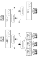
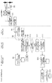
各種のデバイスがネットワーク化されると、これらから発生する情報を取り込んだり、制御したりする業務アプリケーションとの接続が発生する。例えば、コンピュータ化された工作機械からの工程進捗データに基づいて生産ライン全体の調整を行うような生産管理システムや、温度センサからの出力値である温度情報に基づいて予め設定された設定された温度に調整するための環境アプリケーションシステム等、さまざまなアプリケーションシステムが存在する。例えば、図1は代表的な製造業におけるシステム構成を示す。これらはサブシステム(例えば生産管理システム92、受発注システム94、工作機械稼働システム96、生産ラインシステム98)の各々に、相互に異なるデータ構造とプロトコルを実装している。
【0008】
上記のように発生する情報を取り込んだり、制御情報を出力したりするアプリケーションパッケージにはSCADAがある。SCADAソフトウェアはFA分野における代表的なソリューションと言える。このSCADAソフトウェアは、一般にパーソナルコンピュータで動作し、PLC(プログラマブル・ロジック・コントローラ)からの生産ライン情報を収集し、予め設定された条件を満足すると、他のPLCに接続された生産ラインに制御情報を出力したり、他のアプリケーションに情報を出力したりする。
【0009】
【発明が解決しようとする課題】
しかし、このようなソリューションはそれぞれが別々の生い立ちを持って確立されてきた技術であり、他のソリューションとは互換性の点で考慮されていない場合が多い。例えば先のSCADAは対象とするPLCやプラントのハードウェア仕様やDeviceNet等の業界通信プロトコルと強く結びついているため、製造業全体をカバーするような汎用的製品となりにくいのが実情である。すなわち、ソリューション間におけるデータ、プロトコル、操作の非互換性が管理コスト、実装コストの増加を招いている。
【0010】
そのため、現在においては、アプリケーションを含めた企業内の様々なシステムリソースの統合が可能であるミドルソフトウェアが必要とされる。このミドルソフトウェアとしては、はディジタルデバイス、レガシーデバイス、業務アプリケーションそれぞれのデータ構造(スキーマ)、プロトコル、アクセス手法に依存せずに、データ形式の変換、プロコトル変換、ルーティングが可能であることが強く求められる。即ち、ディジタルデバイス、レガシーデバイス及び業務アプリケーションのそれぞれにおいて、データ形式やプロコトル等の互換性を持たせるための改変を施すことは非常に処理負担が大きく、コスト増加を招く。特にレガシーデバイス等への改変は技術的に困難であることが多く、現実的な対応とは考えがたい。
【0011】
本発明は、自己説明型XMLと、これを解釈し業務アプリケーションへプロトコルや物理的なデータ構造に依存しないAPI(アプリケーションプログラムインタフェース)を提供するためのミドルソフトウェアシステムを構築し、データフォーマットやアクセス方法等が相互に異なる複数のコンピュータシステム、ディジタルデバイス、レガシーデバイス等を円滑に統合化することができる統合化システムを提供することを目的とする。
【0012】
【課題を解決するための手段】
上記目的を達成するために、本発明に係る統合化システムは、請求項1に記載したように、レガシーデバイス、ディジタルデバイス及び業務アプリケーションプログラムを含んで構成される入出力機器に関する入出力データ構造、入出力プロコトル及びアクセス手段を、自己説明型XML文書として送信可能なデバイスエージェントモジュールと、前記入出力データ構造、入出力プロコトル及びアクセス手段に基づいて前記入出力機器からの入力データを受け取り、当該入力データに対し所定の処理を行い、当該処理結果としての出力データを出力する機能を持つ、オブジェクト指向言語で記述されたバックエンドアプリケーションと、前記入出力機器からの自己説明型XML文書を解釈し、当該解釈で得られた前記入出力データ構造、入出力プロコトル及びアクセス手段の情報及び前記入出力機器からの入力データを前記バックエンドアプリケーションへ送信するとともに、前記バックエンドアプリケーションからの出力データを前記入出力機器へ送信するミドルソフトウェアシステムとを備えたことを特徴とする。
【0013】
本発明に係る統合化システムでは、特に、デバイスエージェントモジュールが入出力機器に関する入出力データ構造、入出力プロコトル及びアクセス手段を、自己説明型XML文書として送信可能とされた点、及び、デバイスエージェントモジュールとバックエンドアプリケーションとを中継するミドルソフトウェアシステムを設けた点をポイントとする。
【0014】
即ち、デバイスエージェントモジュールが、各種の入出力機器に関する入出力データ構造、入出力プロコトル及びアクセス手段を、自己説明型XML文書として送信すると、ミドルソフトウェアシステムが、当該自己説明型XML文書を受け取って解釈し、当該解釈で得られた入出力データ構造、入出力プロコトル及びアクセス手段の情報及び入出力機器からの入力データをバックエンドアプリケーションへ送信する。
【0015】
これらを受信したバックエンドアプリケーションは、入出力データ構造、入出力プロコトル及びアクセス手段に基づいて入出力機器からの入力データを受け取り、当該入力データに対し所定の処理を行い、当該処理結果としての出力データを出力する。そして、ミドルソフトウェアシステムが、バックエンドアプリケーションからの出力データを入出力機器へ送信する。
【0016】
上記のようにミドルソフトウェアシステムが、各種の入出力機器に関する入出力データ構造、入出力プロコトル及びアクセス手段を表す自己説明型XML文書を自動的に解釈し、入出力機器とバックエンドアプリケーション間のデータを中継するため、入出力機器又はバックエンドアプリケーションが通信相手のデータフォーマットやアクセス方法等に適合させるための処理を行う必要がなく、データフォーマットやアクセス方法等が相互に異なる複数のコンピュータシステム、ディジタルデバイス、レガシーデバイス等を円滑に統合化することができる。
【0017】
本発明に係る統合化システムは、具体的には、以下の構成とすることができる。
【0018】
本発明に係る統合化システムでは、請求項2に記載したように、前記ミドルソフトウェアシステムは、前記デバイスエージェントモジュールから自己説明型XML文書を受信するリスナープログラムと、受信された自己説明型XML文書を解釈し、解釈結果に基づいてJava言語によるクラスオブジェクトを生成するジェネレータプログラムと、生成されたクラスオブジェクトを格納するディレクトリサービスプログラムと、前記ディレクトリサービスプログラムを管理するディレクトリ管理プログラムと、当該ミドルソフトウェアシステムにおける処理実行を制御するカーネルプログラムと、前記バックエンドアプリケーション間のワークフローを定義するワークベンチプログラムとを含んで構成することができる。
【0019】
また、請求項3に記載したように、前記デバイスエージェントモジュールは、前記入出力機器の内部に常駐し、当該入出力機器に関する入出力データ構造、入出力プロコトル及びアクセス手段を解析し、解析結果に基づいて前記自己説明型XML文書を生成する構成とすることができる。
【0020】
一般に、入出力機械はさまざまなデータソースを持つ。例えば工作機械では、各種のセンサ情報例えば、油温、水温、ガス圧、冷却水伝導率等を持ち、これらはそれぞれの工作機械機械種別、工作機械メーカごとにさまざまである。また、業務アプリケーションプログラムである生産管理パッケージソフトウェアや受発注パッケージソフトウェアもさまざまな形式の入出力値を持つ。このため、上記のようにデバイスエージェントモジュールが入出力機器に関する入出力データ構造、入出力プロコトル及びアクセス手段を解析し、解析結果に基づいて自己説明型XML文書を生成する構成とすることで、既存のシステムに追加・修正を加えることなく、各入出力機器に関する入出力データ構造、入出力プロコトル及びアクセス手段の情報を得るしくみを構築することができる。
【0021】
また、請求項4に記載したように、前記デバイスエージェントモジュールに、それぞれ一意のデバイス識別情報が割り当てられた構成とすることができる。これにより、各入出力機器が統合化システム内でユニークであることを保証することができる。
【0022】
また、請求項5に記載したように、前記自己説明型XML文書は、生成したデバイスエージェントモジュールに割り当てられたデバイス識別情報が記述された識別情報部と、対象の入出力機器の入出力データ構造が記述されたデータ構造部と、対象の入出力機器の入出力動作に必要なプロトコルが記述されたプロトコル情報部と、前記データ構造部と前記プロトコル情報部とをマッピングするための情報が記述されたメッセージ情報部とを含んで構成することができる。
【0023】
また、請求項6に記載したように、前記入出力機器の入出力データ構造又は入出力プロトコルが変化した場合、前記デバイスエージェントモジュールは、新たに最新の情報に基づいて自己説明型XML文書を生成する構成とすることができる。この場合、入出力機器の入出力データ構造又は入出力プロトコルが変化しても、最新の情報に基づいて自己説明型XML文書がデバイスエージェントモジュールにより生成されることとなる。
【0024】
また、請求項7に記載したように、前記リスナープログラムは、特定のプロトコル(例えば、HTTP、SMTP等)を解釈するためのプロトコル毎のアダプタモジュールを実装し、前記アダプタモジュールによって、前記デバイスエージェントモジュールから伝送される自己説明型XML文書を解釈可能な構成とすることができる。この場合、リスナープログラムは、プロトコル毎のアダプタモジュールによって、さまざまなプロトコルによる自己説明型XML文書の解釈が可能となる。
【0025】
また、請求項8に記載したように、前記リスナープログラムは、前記入出力機器がデバイスエージェントモジュールを内蔵できない場合、当該入出力機器に対応するデバイスエージェントモジュールをアダプタモジュールに内蔵した構成とすることができる。この場合、入出力機器とリスナープログラムは、入出力機器独自のプロトコルで通信を行い、デバイスエージェントモジュールを内蔵したアダプタモジュールが、自己説明型XML文書を生成することが可能となる。即ち、入出力機器がデバイスエージェントモジュールを内蔵できない場合であっても、当該入出力機器も含めて複数システムを円滑に統合化することができる。
【0026】
また、請求項9に記載したように、前記ミドルソフトウェアシステムは、前記デバイスエージェントモジュールから受信した自己説明型XML文書を解析し、解析で得られたデバイス識別情報、入出力機器と通信を行うための入出力データ構造、プロトコル及びネットワークアドレスを、前記ディレクトリサービスプログラムに蓄積する構成とすることができる。
【0027】
また、請求項10に記載したように、前記ミドルソフトシステムでは、デバイスエージェントモジュールから受信した自己説明型XML文書から、データ入出力検証用のオブジェクト指向言語に基づくクラスオブジェクトが生成され、生成されたクラスオブジェクトは前記ディレクトリサービスプログラムによって蓄積される構成とすることができる。
【0028】
また、請求項11に記載したように、最新のクラスオブジェクトは、ミドルソフトウェアシステム内にキャッシュ化される構成とすることができる。この場合、ミドルソフトウェアシステムによる処理のパフォーマンス効率を向上させることができる。
【0029】
また、請求項12に記載したように、前記ミドルソフトウェアシステムでは、入出力機器のデータ構成が変化した場合に送信される新たな自己説明型XML文書がクラスオブジェクト化され、最新の自己説明型XML文書と前回の自己説明型XML文書とのハッシュ値の相違に基づいて、自己説明型XML文書がバージョン管理される構成とすることができる。即ち、ハッシュ値が前回の自己説明型XML文書と異なる場合にのみ、クラスオブジェクトの生成をすることで、統合化システムにおける効率良い運用を実現し、無駄な処理を省くことができる。
【0030】
また、請求項13に記載したように、前記ミドルソフトウェアシステムは、前記自己説明型XML文書に基づいて、入出力機器とのプロトコル及びデータ構造に依存しない前記バックエンドアプリケーションのためのアクセス手段として、オブジェクト指向言語仕様に基づくアプリケーションプログラムインタフェースを生成する構成とすることができる。この場合、バックエンドアプリケーションが、入出力機器毎に存する入出力の特性を考慮する必要がなくなるという利点がある。
【0031】
【発明の実施の形態】
以下、添付図面に基づき、本発明に関する実施の形態について説明する。尚、各図において同一要素には同一符号を付して説明を省略する。また、本実施形態では、入出力機器間のデータ符号化形式、データ交換形式としてXML文書を利用する。XML(拡張可能型マークアップ言語:eXtensible Markup Language)は、データソース間で共通のデータ形式を定義する。XMLはデータソースに独自の「型」の定義を可能とするが、本発明においては「型」はW3C(World Wide Web Consortium)において定義されたXMLスキーマ言語の型に従う。
【0032】
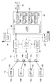
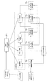
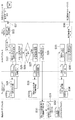
図2には、本実施形態に係る製造業企業内のサブシステム間を統合するための統合化システム1の構成例を示す。この統合化システム1における入出力機器10としては、工作機械10A、生産ライン10B、生産管理パッケージソフトウェア10C及び受発注パッケージソフトウェア10Dから構成される。原則的に入出力機器10の内部には、デバイスエージェントモジュール12A等(デバイスエージェントモジュール12と総称する)が常駐し、デバイスエージェントモジュール12は、これらの入出力データ構造と入出力プロトコルを解析して、自己説明型XML文書を生成する。入出力機器10の入出力データ構造や入出力プロトコルが変化した場合、デバイスエージェントモジュール12は、新たに最新の情報に基づいて自己説明型XML文書を生成する。なお、デバイスエージェントモジュール12には、それぞれ一意のデバイス識別情報が割り当てられる。
【0033】
統合化システム1におけるバックエンドプログラムは、Java言語によるEJB(Enterprise Java Bean)プログラム32として構築され、EJBブログラム32はアプリケーションサーバ30上で実行される。EJBブログラム32のうち加工指示EJBブログラム32Aは工作機械や生産ラインを動作させるためのEJBプログラムであり、データベース36に存在する加工制御データを統合化システム1に送り込み、工作機械や生産ラインを実行制御する。ここでの加工制御データは工作機械や生産ライン装置が判読できる数値制御データでも良いし、装置に送り込めるマイクロプログラムでも良い。また、実績収集EJBブログラム32Bは工作機械や生産ラインからの動作実績、障害情報を収集するEJBプログラムであり、計画指示EJBブログラム32Cは新規受注データを生産管理パッケージに送信するためのEJBプログラムである。更に、生産実績EJBブログラム32Dは、収集された実績データを生産管理パッケージに送信するためのEJBプログラムである。
【0034】
統合化システム1におけるミドルソフトウェアシステムは、Java言語によって構築され、リスナープログラム16、ジェネレータプログラム22、ディレクトリサービスプログラム20、ディレクトリ管理プログラム24、カーネルプログラム18、EJB制御プログラム28及びワークベンチプログラム26から構成される。
【0035】
このうちリスナープログラム16は、入出力機器と通信を行うプログラムであり、特定のプロトコルを解釈するためのアダプタモジュール14A、14B、14C、14D(アダプタモジュール14と総称する)を実装し、特定のプロコトルによって入出力機器10から伝送される自己説明型XML文書を受信可能とされている。
【0036】
但し、リスナープログラム16は、入出力機器10がデバイスエージェントモジュール12を内蔵できない場合、例えば、図2の例で生産ライン10Bがデバイスエージェントモジュール12を内蔵できない場合、生産ライン10Bに対応するデバイスエージェントモジュール12Bをアダプタモジュール14Bに内蔵している。上記構成により、生産ライン10Bとリスナープログラム16は、生産ライン10B独自のプロトコルで通信を行い、アダプタモジュール14Bが自己説明型XML文書を生成することが可能である。
【0037】
ジェネレータプログラム22は、入出力機器10が送信する自己説明型XML文書を解釈しクラスオブジェクトを生成するプログラムである。また、ディレクトリサービスプログラム20は、ユーザインタフェースを持ったディレクトリ管理プログラム24により制御され、カーネルプログラム18は、ミドルソフトウェアシステム全体の動作を制御するプログラムである。また、EJB制御プログラム28は、EJBプログラム間のワークフロー制御とミドルソフトウェアシステム間の通信を行うプログラムである。このEJB制御プログラム28は、ユーザインタフェースを持ったワークベンチプログラム26からの指示に基づいてワークフロー制御の調整を行う。ワークフローが変更された場合にはEJB制御プログラム28は、ワークベンチプログラム26からの変更指示に基づいて、呼び出す対象のEJBプログラムを変更する。更に、ワークベンチプログラム26は自己説明型XML文書から入出力クラスライブラリ34A、34B、34C、34D(入出力クラスライブラリ34と総称する)を生成できる。入出力クラスライブラリ34はJava言語によるテンプレートプログラムであり、コンパイル時にEJBプログラム32とリンクすることができる。
【0038】
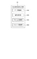
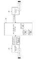
図3及び図4には、デバイスエージェントモジュール12が生成する自己説明型XML文書40の構成を示す。自己説明型XML文書40は、XMLスキーマ言語によって記述された入力用構造と出力用構造が記述されたデータ構造部40Aと、発信元を一意に特定するためのデバイスID(DID)が記述されている識別情報部40Bと、入出力動作に必要なプロトコルが記述されるプロトコル情報部40Cと、入出力において使用するデータ構造部40Aとプロトコル情報部40Cをマッピングするための情報を記述されるメッセージ情報部40Dとを含んで構成される。
【0039】
なお、データ構造部40Aに含まれるデータ構造には、XMLスキーマ言語に合致したそれぞれのデータ型(文字型、整数型等)、とりうる値の範囲、及び出現回数の指定を行うことができる。データ構造部40Aに記述するデータ構造は図4のように親子関係を持っていても良いし、持っていなくてもよい。また他の親構造を子構造として取り込んでも良い。
【0040】
また、識別情報部40BのデバイスID(DID)は管理者によって与えられるものであっても良いし、ネットワークアドレスのような一意の識別子でもよい。
【0041】
また、プロトコル情報部40Cにはデータ構造をどのような通信プロトコルを使用して配信するのかが記述される。プロトコル情報部40Cにはプロトコルを識別するためのプロトコル名と、使用ネットワークにおける実際の伝送に必要なパラメータが記述される。例えばHTTP(Hyper Text Transmission Protocol)であればURLである。
【0042】
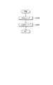
本実施形態の統合化システム1における処理は、図10に示すように、入出力機器10が自己説明型XML文書をミドルソフトウェアシステムに送信する告知フェーズS100と、入出力機器10とミドルソフトウェアシステム間が実際の入出力データを送受信する入出力フェーズS200とから構成される。以下、これら告知フェーズ及び入出力フェーズを順に説明する。
【0043】
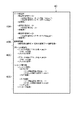
図5には本実施形態に係る告知フェーズにおける処理フローを示す。まず、工作機械や生産管理パッケージの管理者は、入出力機器10のデバイスエージェントモジュール12に一意のDIDを設定する(図5のS1)。デバイスエージェントモジュール12は独自のユーザインタフェースを持って管理者から入力されたDIDを保持しても良い。また、デバイスエージェントモジュール12はDIDを、予めコンピュータシステム上のメモリに格納したり、ある種のデータベースに格納してもよい。
【0044】
次に、工作機械や生産管理パッケージの管理者はデバイスエージェントモジュール12を動作させ(S2)、デバイスエージェントモジュール12は対象の工作機械やアプリケーションの定義情報から図3及び図4のような自己説明型XMLを生成する(S3)。この定義情報とは、ハードディスク装置に格納されたテキストファイルであったり、コンピュータシステム上のメモリに格納されていたり、ある種のデータベースに格納されていてもよい。
【0045】
生成された自己説明型XMLは、TCP/IP等のプロトコルを用いてインターネットやLANを経由してリスナープログラム16に配信される(S4)。リスナープログラム16は工作機械や生産管理パッケージといった入出力機器10の内部に存在していてもよく、この場合には、内部プロセス間通信機構によって配信される。デバイスエージェントモジュール12とリスナープログラム16間にファイアウォールが存在する場合にはHTTPプロトコル等のファイアウォール透過プロトコルによってラッピングされてもよい。
【0046】
リスナープログラム16は、受信した自己説明型XML文書中の識別情報部のDIDと、入出力機器10のネットワークアドレスと、リスナープログラム16自身の識別子(リスナーID)とをディレクトリサービスプログラム20に登録する(S5)。ディレクトリサービスプログラム20は、DIDを登録キーにして入出力機器10のネットワークアドレスとリスナーIDとを自身のデータベースに登録する(S6)。登録された情報はディレクトリ管理プログラム24のユーザインタフェースから参照したり、削除したりすることができる。
【0047】
さらにリスナープログラム16は、受信した自己説明型XML文書をジェネレータプログラム22に引き渡す(S7)。
【0048】
ジェネレータプログラム22は自己説明型XML文書から一方向ハッシュ関数を用いて、一意のハッシュ値を生成する(S8)。ジェネレータプログラム22は自己説明型XML文書をDOM(Document Object Model)に基づいたオブジェクトとしてメモリに展開する。そして、DIDを検索キーとしてハッシュ値を検索し(S9)、ハッシュ値がDIDと合致しない場合(S10で否定判断の場合)に、以下のようにしてメッセージ処理クラスオブジェクトを生成する(S11)。
【0049】
ここで、図6を用いてジェネレータプログラム22による解析処理及びメッセージ処理クラスオブジェクト生成処理を説明する。ジェネレータプログラム22は、図6に示す以下の処理T1〜T6を実行する。
【0050】
即ち、ジェネレータプログラム22は、情報解析処理T1において、自己説明型XML文書を解析してメモリ上に各種の解析情報(識別情報、プロトコル情報、メッセージ情報、データ構造)を作成する。そして、ジェネレータプログラム22は、メッセージ依存関係解析処理T2において、メッセージ情報の情報同士の依存関係を解析し、その際にデータ構造が関係するか否かを調べる。
【0051】
ここで、データ構造が関係する場合には、ジェネレータプログラム22は、データ依存関係解析処理T3において、データ構造の依存関係を解析する。また、ジェネレータプログラム22は、メッセージデータ型解析処理T4において、メッセージ情報からメッセージ情報に含まれるデータの型の構成情報を解析してデータ構成情報を作成する。
【0052】
また、データ構造が関係する場合には、ジェネレータプログラム22は、データ構造データ型解析処理T5において、データ構造のデータの型の構成情報を解析してデータ構成情報に追加する。更に、ジェネレータプログラム22は、データチェック情報作成処理T6において、データ構成情報と識別情報からメッセージ処理クラスオブジェクトを動的に生成する。
【0053】
以上のようにしてメッセージ処理クラスオブジェクトを生成した後、図5のようにジェネレータプログラム22は、動的に生成したメッセージ処理クラスオブジェクトとハッシュ値とを、識別情報部40Bに格納されているDIDを登録キーにして登録するべく、メッセージ処理クラスオブジェクト、ハッシュ値及びDIDを一組にしてディレクトリサービスプログラム20に渡す(図5のS12)。
【0054】
そして、ディレクトリサービスプログラム20は、DIDを登録キーにしてメッセージ処理クラスオブジェクトとハッシュ値を自身のデータベースにデバイス情報として登録する(S13)。登録されたデバイス情報はディレクトリ管理プログラム24のユーザインタフェースから参照したり、削除したりすることができる。
【0055】
ワークベンチプログラム26は、登録されたメッセージ処理クラスオブジェクトから入出力クラスライブラリ34を生成する(S14)。入出力クラスライブラリ34はJava言語によるテンプレートプログラムであり、コンパイル時にEJBプログラム32とリンクすることができる。
【0056】
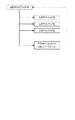
ここで、図7及び図8を用いてディレクトリ管理プログラム24及びワークベンチプログラム26の処理を補足的に説明する。図7に示すように、ディレクトリ管理プログラム24はユーザインタフェースを利用して、アプリケーションサーバ情報としてアプリケーションサーバ30(図2)のネットワークアドレスと、EJBプログラム情報としてアプリケーションサーバ30上のEJBプログラム32のオブジェクトクラス名とオブジェクトメソッド名とをディレクトリサービスプログラム20に登録することができる。
【0057】
図8に示すように、これらのアプリケーションサーバ情報(アプリケーションサーバ30のネットワークアドレス情報)とEJBプログラム情報(アプリケーションサーバ30上のEJBプログラム32のオブジェクトクラス名とオブジェクトメソッド名)は、EJBクラスオブジェクト名からクラスメソッド名及びアプリケーションサーバ30のネットワークアドレスへのリンクリストとして、ディレクトリサービスプログラム20内のデータベースに保存される。但し、アプリケーションサーバのネットワークアドレスからEJBクラスオブジェクト名へのリンク情報も保存されている。
【0058】
一方、ワークベンチプログラム26は、ディレクトリ管理プログラム24が登録したEJBプログラム情報を読み込み、ユーザインタフェース上にアイコンとして表示できる。ワークベンチプログラム26の操作者は、入出力機器10が出力したデータをどのEJBプログラム32に引き渡すかを定義できる。また、EJBプログラム32のアイコン同士をグラフィカルな線で接続することによって、EJBプログラム32間の実行順序を定義できる。ワークベンチプログラム26が定義したワークフロー情報はディレクトリサービスプログラム20に格納される。
【0059】
次に、図9を用いて入出力フェーズ(図10のS200)を説明する。この入出力フェーズは、図2の受発注パッケージソフトウェア10Dから発生した出力データを計画指示EJBプログラム32Cが処理し、生産管理パッケージソフトウェア10Cへ送出するフェーズである。
【0060】
入出力機器としての受発注パッケージソフトウェア10Dがデータの出力を行う場合、告知フェーズで送信した自己説明型XML文書の出力構造と合致するデータ構造とプロトコルを使用してデータの出力を行う。また、出力パケットには、出力データと入出力機器(受発注パッケージソフトウェア10D)のDIDとが含まれている。出力パケットはインターネットやLANを経由してリスナープログラム16が受信する(S21)。出力データを受信したリスナープログラム16はカーネルプログラム18に出力パケットを渡す(S22)。
【0061】
例えば、受発注パッケージソフトウェア10Dは、受注情報と受発注パッケージソフトウェア10Dに定義されたDIDとを、出力データとしてミドルソフトウェアシステムに送信する(S21)。ミドルソフトウェアシステム内のリスナープログラム16は出力データを受信し、カーネルプログラム18に送信する(S22)。カーネルプログラム18は、DIDをキーとしてメッセージ処理クラスを取得する(S23)。具体的には、カーネルプログラム18は、ディレクトリサービスプログラム20からDIDをキーとしてメッセージ処理クラスを検索することで(S24)、JAVAメッセージ処理クラスを得る。
【0062】
S24の検索によりメッセージ処理クラスが得られると、カーネルプログラム18は、当該メッセージ処理クラスをインスタンス化し(S25)、出力データが正常ならば(S26で肯定判断ならば)、DIDをキーとして、計画指示EJBプログラム32Cを呼び出すために必要な情報(EJB呼出情報)を取得する(S27)。具体的には、カーネルプログラム18は、ディレクトリサービスプログラム20からDIDをキーとしてEJB呼出情報を検索することで(S28)、EJB呼出情報を得る。EJB呼出情報としては、例えば、計画指示EJBプログラム32Cのクラスオブジェクト名、クラスメソッド名、及び、計画指示EJBプログラムが動作するアプリケーションサーバのネットワークアドレスが挙げられる。
【0063】
そして、カーネルプログラム18は、受注情報を引数として計画指示EJBプログラム32Cを呼び出す(S29)。
【0064】
計画指示EJBプログラム32Cは、製品ごとの生産数量を算出し生産基礎データを生成する(S30)。そして、生産基礎データをパラメータとして入出力クラスライブラリ34Cをコールする(S31)。
【0065】
入出力クラスライブラリ34Cは、カーネルプログラム18を呼び出し生産量基礎データを渡す(S32)。また、この際に、入出力クラスライブラリ34Cは、あて先となる生産管理パッケージソフトウェア10Cを特定するためのDIDも同時にカーネルプログラム18に渡す(S32)。
【0066】
カーネルプログラム18は、DIDをキーとしてリスナーIDを取得する(S33)。具体的には、カーネルプログラム18は、ディレクトリサービスプログラム20からDIDをキーとしてリスナーIDを検索することで(S34)、DIDを持った生産管理パッケージソフトウェア10Cが自己説明型XMLを送信した先のリスナープログラムのリスナーIDを得る。
【0067】
そして、カーネルプログラム18は、当該リスナーIDに該当するリスナープログラム16を呼び出すと(S35)、当該リスナープログラム16に生産量基礎データを渡す。このリスナープログラム16は生産量基礎データを生産管理パッケージソフトウェア10Cに送信する(S36)。
【0068】
以上説明した本発明の実施形態により、図2のミドルソフトウェアシステム16、18、20、22、24、26、28が、各種の入出力機器10に関する入出力データ構造、入出力プロコトル及びアクセス手段を表す自己説明型XML文書を自動的に解釈し、入出力機器10と、バックエンドアプリケーションであるEJBプログラム32との間のデータを中継するため、入出力機器10又はEJBプログラム32が通信相手のデータフォーマットやアクセス方法等に適合させるための処理を行う必要がなく、データフォーマットやアクセス方法等が相互に異なる複数のコンピュータシステム、ディジタルデバイス、レガシーデバイス等を円滑に統合化することができる。
【0069】
なお、上記のような統合化システムにおけるミドルソフトウェアシステム内のプログラムの各々は、複数のコンピュータシステムに分散してインストールされていてもよいし、一台のコンピュータシステムに集中的にインスト−ルされていてもよい。
【0070】
また、ミドルソフトウェアシステム内のプログラム(リスナープログラム、ジェネレータプログラム、ディレクトリサービスプログラム、ディレクトリ管理プログラム、カーネルプログラム)は、Java言語、C++言語等のオブジェクト指向言語で作成され、磁気ディスクにインストールされている構成を採ることができる。
【0071】
また、ディレクトリ管理プログラムは、ディレクトリサービスプログラムに蓄積された入出力機器のDID、データ構造、使用プロトコル及びネットワークアドレスをデバイス情報としてディレクトリ管理プログラムの画面上のアイコンとして表示する構成を採ることができる。
【0072】
また、ディレクトリ管理プログラムを使用して、ディレクトリサービスプログラムに対してバックエンドアプリケーションのネットワークアドレス、オブジェクトクラス名、オブジェクトメソッド名をバックエンドアプリケーション情報として登録でき、これらをディレクトリ管理プログラムの画面上のアイコンとして表示する構成を採ることができる。
【0073】
また、ワークベンチプログラムはディレクトリサービスプログラムのデバイス情報とバックエンドアプリケーション情報を参照して、アイコンのクリックアンドドラッグ操作により、デバイス情報アイコンとバックエンドアプリケーション情報アイコンを結びつけることができる。このような操作によって入出力機器とバックエンドアプリケーション間の経路制御(ルーティング)が可能になる。
【0074】
また、デバイスエージェントモジュールは、Java言語、C++言語等のオブジェクト指向言語で作成され、ネットワークサーバから供給される態様、入出力機器の一部として取り込まれている態様、独立したプログラムとして磁気ディスクにインストールされている態様の何れの態様を採用してもよい。
【0075】
【発明の効果】
以上説明したように、本発明によれば、ミドルソフトウェアシステムが、各種の入出力機器に関する入出力データ構造、入出力プロコトル及びアクセス手段を表す自己説明型XML文書を自動的に解釈し、入出力機器とバックエンドアプリケーション間のデータを中継するため、入出力機器又はバックエンドアプリケーションが通信相手のデータフォーマットやアクセス方法等に適合させるための処理を行う必要がなく、データフォーマットやアクセス方法等が相互に異なる複数のコンピュータシステム、ディジタルデバイス、レガシーデバイス等を円滑に統合化することができる。
【図面の簡単な説明】
【図1】代表的な製造業におけるシステム構成例を示す図である。
【図2】本実施形態における統合化システムのシステム構成図である。
【図3】自己説明型XML文書の構成図である。
【図4】自己説明型XML文書のデータ構造を説明するための図である。
【図5】告知フェーズにおける処理を示すフロー図である。
【図6】ジェネレータプログラムにおける解析処理を説明するための図である。
【図7】ディレクトリ管理プログラム及びワークベンチプログラムの処理を示す図である。
【図8】EJBクラスオブジェクト名及びEJBクラスメソッド名のリンク構造を示す図である。
【図9】入出力フェーズにおける処理を示すフロー図である。
【図10】統合化システムにおける処理概要を示すフロー図である。
【符号の説明】
1…統合化システム、10…入出力機器、10A…工作機械、10B…生産ライン、10C…生産管理パッケージソフトウェア、10D…受発注パッケージソフトウェア、12…デバイスエージェントモジュール、14…アダプタモジュール、16…リスナープログラム、18…カーネルプログラム、20…ディレクトリサービスプログラム、22…ジェネレータプログラム、24…ディレクトリ管理プログラム、26…ワークベンチプログラム、28…制御プログラム、30…アプリケーションサーバ、32…EJBブログラム、34…入出力クラスライブラリ、36…データベース、40…自己説明型XML文書、40A…データ構造部、40B…識別情報部、40C…プロトコル情報部、40D…メッセージ情報部、92…生産管理システム、94…受発注システム、96…工作機械稼働システム、98…生産ラインシステム、S100…告知フェーズ、S200…入出力フェーズ、T1…情報解析処理、T2…メッセージ依存関係解析処理、T3…データ依存関係解析処理、T4…メッセージデータ型解析処理、T5…データ構造データ型解析処理、T6…データチェック情報作成処理。[0001]
TECHNICAL FIELD OF THE INVENTION
The present invention relates to an integrated system for integrating various system resources in a company including legacy devices such as machine tools and sensor devices, digital devices such as PDAs, and business application programs.
[0002]
The “input / output device” in the present specification is a concept including both hardware resources such as legacy devices and digital devices and software resources such as business application programs.
[0003]
[Prior art]
The Internet is growing into a network connecting PCs, UNIX servers, mainframes, and all kinds of information devices such as mobile phones and PDAs. Underpinning this are computer systems that have made remarkable progress, and companies have somehow adopted computer systems and network systems such as the Internet.
[0004]
Despite the remarkable development of networks in the last ten years, the contents handled by advanced information devices are characters, sounds, and images that can be understood by humans, and have not changed much. In view of the latest information technology trends in recent years, large-scale enterprise systems using the concept of Web Services using these information devices and the Internet are expected to become mainstream.
[0005]
On the other hand, information devices such as sensors, barcodes, RFIDs, and IC cards that use data that does not need to be directly understood by humans are increasing rapidly. These information devices, both in number and in the amount of information that will be generated, are orders of magnitude larger than information devices currently connected to the Internet. Explosive development beyond that is expected.
[0006]
Due to technological innovation and mass production effects, digital devices are becoming smaller, less expensive, and more sophisticated.Thus, everything is becoming digital devices, and legacy devices such as temperature sensors and industrial machines can be connected to networks. The number of connected cases is increasing.
[0007]
When various devices are networked, a connection with a business application that takes in and controls information generated from these devices occurs. For example, a production management system that adjusts the entire production line based on process progress data from a computerized machine tool, or a preset value set based on temperature information that is an output value from a temperature sensor. There are various application systems, such as an environmental application system for adjusting to a temperature. For example, FIG. 1 shows a system configuration in a typical manufacturing industry. These sub-systems (for example, a
[0008]
SCADA is an application package that captures information generated as described above and outputs control information. SCADA software is a typical solution in the FA field. The SCADA software generally operates on a personal computer, collects production line information from a PLC (Programmable Logic Controller), and when a preset condition is satisfied, sends control information to a production line connected to another PLC. Or output information to other applications.
[0009]
[Problems to be solved by the invention]
However, such solutions are technologies that have been established with different backgrounds, and are often not considered in terms of compatibility with other solutions. For example, SCADA is strongly tied to the hardware specifications of the target PLC or plant, or to industry communication protocols such as DeviceNet, so that it is difficult for it to be a general-purpose product that covers the entire manufacturing industry. In other words, incompatibility of data, protocols, and operations between solutions causes an increase in management costs and implementation costs.
[0010]
Therefore, at present, middle software that can integrate various system resources in a company including an application is required. This middle software is strongly required to be capable of data format conversion, protocol conversion, and routing without depending on the data structure (schema), protocol, and access method of digital devices, legacy devices, and business applications. Can be That is, in each of the digital device, the legacy device, and the business application, modifying the data format, the protocol, and the like to make them compatible has a very large processing load and causes an increase in cost. In particular, it is often technically difficult to change to a legacy device or the like, and it cannot be considered a realistic response.
[0011]
The present invention constructs a self-explanatory XML and a middle software system for interpreting the XML and providing an API (application program interface) that does not depend on a protocol or a physical data structure to a business application, and provides a data format and an access method. It is an object of the present invention to provide an integrated system capable of smoothly integrating a plurality of computer systems, digital devices, legacy devices, and the like, which are different from each other.
[0012]
[Means for Solving the Problems]
In order to achieve the above object, an integrated system according to the present invention includes, as described in claim 1, an input / output data structure related to an input / output device including a legacy device, a digital device, and a business application program, A device agent module capable of transmitting the input / output protocol and the access means as a self-explanatory XML document; and receiving input data from the input / output device based on the input / output data structure, the input / output protocol and the access means, and Interpret a back-end application described in an object-oriented language having a function of performing predetermined processing on data and outputting output data as the processing result, and a self-explanatory XML document from the input / output device, The input / output data structure obtained by the interpretation, input / output A middle software system for transmitting information of the protocol and access means and input data from the input / output device to the back-end application, and transmitting output data from the back-end application to the input / output device. Features.
[0013]
In the integrated system according to the present invention, in particular, the device agent module can transmit an input / output data structure, an input / output protocol, and an access unit relating to an input / output device as a self-explanatory XML document. The point is that a middle software system for relaying between the server and the back-end application is provided.
[0014]
That is, when the device agent module transmits an input / output data structure, an input / output protocol, and an access means relating to various input / output devices as a self-explanatory XML document, the middle software system receives and interprets the self-explanatory XML document. Then, the input / output data structure, information on the input / output protocol and the access means obtained by the interpretation, and input data from the input / output device are transmitted to the back-end application.
[0015]
The back-end application receiving these receives the input data from the input / output device based on the input / output data structure, the input / output protocol, and the access means, performs predetermined processing on the input data, and outputs the processing result. Output data. Then, the middle software system transmits output data from the back-end application to the input / output device.
[0016]
As described above, the middle software system automatically interprets the self-explanatory XML document representing the input / output data structure, input / output protocol, and access means for various input / output devices, and outputs data between the input / output devices and the back-end application. It is not necessary for input / output devices or back-end applications to perform processing for adapting to the data format and access method of the communication partner, and multiple computer systems with different data formats and access methods, digital Devices, legacy devices, and the like can be smoothly integrated.
[0017]
Specifically, the integrated system according to the present invention can have the following configuration.
[0018]
In the integrated system according to the present invention, as described in
[0019]
In addition, as described in
[0020]
Generally, input / output machines have various data sources. For example, a machine tool has various types of sensor information, for example, oil temperature, water temperature, gas pressure, cooling water conductivity, and the like, which vary depending on each machine tool type and machine tool maker. Further, production management package software and ordering package software, which are business application programs, also have input / output values in various formats. Therefore, as described above, the device agent module analyzes the input / output data structure, the input / output protocol, and the access means for the input / output device, and generates a self-explanatory XML document based on the analysis result. Without adding or modifying the system, it is possible to construct a mechanism for obtaining information on an input / output data structure, an input / output protocol, and access means for each input / output device.
[0021]
Further, as described in
[0022]
As described in
[0023]
When the input / output data structure or the input / output protocol of the input / output device changes, the device agent module generates a self-explanatory XML document based on the latest information. Configuration. In this case, even if the input / output data structure or the input / output protocol of the input / output device changes, a self-explanatory XML document is generated by the device agent module based on the latest information.
[0024]
Further, as described in claim 7, the listener program implements an adapter module for each protocol for interpreting a specific protocol (for example, HTTP, SMTP, etc.), and the device agent module is executed by the adapter module. Can interpret the self-explanatory XML document transmitted from. In this case, the listener program can interpret the self-explanatory XML document by various protocols by the adapter module for each protocol.
[0025]
Further, as set forth in
[0026]
Also, as described in
[0027]
As described in
[0028]
Further, as described in
[0029]
According to the twelfth aspect, in the middle software system, a new self-explanatory XML document transmitted when the data configuration of the input / output device changes is converted into a class object, and the latest self-explanatory XML document is created. The self-explanatory XML document may be version-managed based on the difference between the hash value of the document and the previous self-explanatory XML document. That is, the class object is generated only when the hash value is different from the previous self-explanatory XML document, so that efficient operation in the integrated system can be realized and unnecessary processing can be omitted.
[0030]
Further, as described in
[0031]
BEST MODE FOR CARRYING OUT THE INVENTION
Hereinafter, embodiments of the present invention will be described with reference to the accompanying drawings. In the drawings, the same elements are denoted by the same reference numerals, and description thereof will be omitted. In this embodiment, an XML document is used as a data encoding format and a data exchange format between input / output devices. XML (Extensible Markup Language) defines a common data format between data sources. XML allows a data source to define its own "type", but in the present invention, the "type" follows the type of the XML schema language defined in the World Wide Web Consortium (W3C).
[0032]
FIG. 2 shows a configuration example of an integrated system 1 for integrating subsystems in a manufacturing company according to the present embodiment. The input /
[0033]
The back-end program in the integrated system 1 is constructed as an EJB (Enterprise Java Bean)
[0034]
The middle software system in the integrated system 1 is constructed by the Java language, and includes a
[0035]
Among them, the
[0036]
However, if the input /
[0037]
The
[0038]
3 and 4 show the configuration of the self-
[0039]
In the data structure included in the
[0040]
Further, the device ID (DID) of the
[0041]
The
[0042]
As shown in FIG. 10, the processing in the integrated system 1 of the present embodiment includes a notification phase S100 in which the input /
[0043]
FIG. 5 shows a processing flow in the notification phase according to the present embodiment. First, the administrator of the machine tool or the production management package sets a unique DID in the device agent module 12 of the input / output device 10 (S1 in FIG. 5). The device agent module 12 may have a unique user interface and hold the DID input from the administrator. The device agent module 12 may store the DID in a memory on the computer system in advance, or may store the DID in a certain database.
[0044]
Next, the manager of the machine tool or the production management package operates the device agent module 12 (S2), and the device agent module 12 uses the self-explanation type as shown in FIGS. 3 and 4 from the definition information of the target machine tool or application. An XML is generated (S3). The definition information may be a text file stored in a hard disk device, stored in a memory on a computer system, or stored in a certain database.
[0045]
The generated self-explanatory XML is distributed to the
[0046]
The
[0047]
Further, the
[0048]
The
[0049]
Here, the analysis processing and the message processing class object generation processing by the
[0050]
That is, in the information analysis process T1, the
[0051]
Here, when the data structure is related, the
[0052]
When the data structure is related, the
[0053]
After generating the message processing class object as described above, the
[0054]
Then, the
[0055]
The
[0056]
Here, the processing of the
[0057]
As shown in FIG. 8, the application server information (network address information of the application server 30) and the EJB program information (the object class name and the object method name of the
[0058]
On the other hand, the
[0059]
Next, the input / output phase (S200 in FIG. 10) will be described with reference to FIG. This input / output phase is a phase in which the plan
[0060]
When the
[0061]
For example, the
[0062]
When the message processing class is obtained by the search in S24, the
[0063]
Then, the
[0064]
The planning
[0065]
The input /
[0066]
The
[0067]
When the
[0068]
According to the embodiment of the present invention described above, the
[0069]
Each of the programs in the middle software system in the integrated system as described above may be installed separately in a plurality of computer systems, or may be installed intensively in one computer system. You may.
[0070]
The programs (listener program, generator program, directory service program, directory management program, and kernel program) in the middle software system are created in an object-oriented language such as Java language or C ++ language and installed on the magnetic disk. Can be adopted.
[0071]
Further, the directory management program can adopt a configuration in which the DID, data structure, used protocol, and network address of the input / output device stored in the directory service program are displayed as device information as icons on the screen of the directory management program.
[0072]
Using the directory management program, the network address, object class name, and object method name of the back-end application can be registered in the directory service program as back-end application information, and these can be registered as icons on the screen of the directory management program. A configuration for displaying can be adopted.
[0073]
The workbench program can link the device information icon and the backend application information icon by clicking and dragging the icon with reference to the device information and the backend application information of the directory service program. By such an operation, a path control (routing) between the input / output device and the back-end application becomes possible.
[0074]
The device agent module is created in an object-oriented language such as the Java language or the C ++ language and supplied from a network server, incorporated as a part of an input / output device, installed on a magnetic disk as an independent program. Any of the embodiments described above may be adopted.
[0075]
【The invention's effect】
As described above, according to the present invention, the middle software system automatically interprets a self-explanatory XML document representing an input / output data structure, an input / output protocol and access means for various input / output devices, and Since the data is relayed between the device and the back-end application, there is no need for the input / output device or the back-end application to perform processing for adapting to the data format and access method of the communication partner. A plurality of different computer systems, digital devices, legacy devices, etc. can be smoothly integrated.
[Brief description of the drawings]
FIG. 1 is a diagram showing an example of a system configuration in a typical manufacturing industry.
FIG. 2 is a system configuration diagram of an integrated system according to the embodiment.
FIG. 3 is a configuration diagram of a self-explanatory XML document.
FIG. 4 is a diagram illustrating a data structure of a self-explanatory XML document.
FIG. 5 is a flowchart showing a process in a notification phase.
FIG. 6 is a diagram for explaining an analysis process in a generator program.
FIG. 7 is a diagram showing processing of a directory management program and a workbench program.
FIG. 8 is a diagram showing a link structure of an EJB class object name and an EJB class method name.
FIG. 9 is a flowchart showing a process in an input / output phase.
FIG. 10 is a flowchart showing an outline of processing in the integrated system.
[Explanation of symbols]
DESCRIPTION OF SYMBOLS 1 ... Integrated system, 10 ... Input / output equipment, 10A ... Machine tool, 10B ... Production line, 10C ... Production management package software, 10D ... Ordering package software, 12 ... Device agent module, 14 ... Adapter module, 16 ... Listener Program: 18: Kernel program, 20: Directory service program, 22: Generator program, 24: Directory management program, 26: Workbench program, 28: Control program, 30: Application server, 32: EJB program, 34: Input / output Class library, 36 database, 40 self-explanatory XML document, 40A data structure section, 40B identification information section, 40C protocol information section, 40D message information section, 92
Claims (13)
前記入出力データ構造、入出力プロコトル及びアクセス手段に基づいて前記入出力機器からの入力データを受け取り、当該入力データに対し所定の処理を行い、当該処理結果としての出力データを出力する機能を持つ、オブジェクト指向言語で記述されたバックエンドアプリケーションと、
前記入出力機器からの自己説明型XML文書を解釈し、当該解釈で得られた前記入出力データ構造、入出力プロコトル及びアクセス手段の情報及び前記入出力機器からの入力データを前記バックエンドアプリケーションへ送信するとともに、前記バックエンドアプリケーションからの出力データを前記入出力機器へ送信するミドルソフトウェアシステムと、
を備えた統合化システム。A device agent module capable of transmitting, as a self-explanatory XML document, an input / output data structure, an input / output protocol, and an access unit relating to an input / output device including a legacy device, a digital device, and a business application program;
It has a function of receiving input data from the input / output device based on the input / output data structure, input / output protocol, and access means, performing a predetermined process on the input data, and outputting output data as a result of the process. , A back-end application written in an object-oriented language,
Interpret the self-explanatory XML document from the input / output device, and send the input / output data structure, input / output protocol and access unit information obtained by the interpretation, and input data from the input / output device to the back-end application. Transmitting, and a middle software system for transmitting output data from the back-end application to the input / output device;
Integrated system with.
前記デバイスエージェントモジュールから自己説明型XML文書を受信するリスナープログラムと、
受信された自己説明型XML文書を解釈し、解釈結果に基づいてJava言語によるクラスオブジェクトを生成するジェネレータプログラムと、
生成されたクラスオブジェクトを格納するディレクトリサービスプログラムと、
前記ディレクトリサービスプログラムを管理するディレクトリ管理プログラムと、
当該ミドルソフトウェアシステムにおける処理実行を制御するカーネルプログラムと、
前記バックエンドアプリケーション間のワークフローを定義するワークベンチプログラムと、
を含んで構成されることを特徴とする請求項1記載の統合化システム。The middle software system,
A listener program for receiving a self-explanatory XML document from the device agent module;
A generator program for interpreting the received self-explanatory XML document and generating a class object in Java language based on the interpretation result;
A directory service program for storing the generated class objects,
A directory management program for managing the directory service program;
A kernel program for controlling processing execution in the middle software system;
A workbench program that defines a workflow between the back-end applications,
The integrated system according to claim 1, wherein the integrated system is configured to include:
前記入出力機器の内部に常駐し、当該入出力機器に関する入出力データ構造、入出力プロコトル及びアクセス手段を解析し、解析結果に基づいて前記自己説明型XML文書を生成することを特徴とする請求項1又は2に記載の統合化システム。The device agent module comprises:
The system according to claim 1, wherein the self-explanatory XML document is generated based on a result of the analysis by resident in the input / output device, analyzing an input / output data structure, an input / output protocol, and an access unit relating to the input / output device. Item 3. The integrated system according to item 1 or 2.
生成したデバイスエージェントモジュールに割り当てられたデバイス識別情報が記述された識別情報部と、
対象の入出力機器の入出力データ構造が記述されたデータ構造部と、
対象の入出力機器の入出力動作に必要なプロトコルが記述されたプロトコル情報部と、
前記データ構造部と前記プロトコル情報部とをマッピングするための情報が記述されたメッセージ情報部と、
を含んで構成されることを特徴とする請求項4記載の統合化システム。The self-explanatory XML document is:
An identification information section in which device identification information assigned to the generated device agent module is described;
A data structure part in which the input / output data structure of the target input / output device is described;
A protocol information section in which a protocol necessary for input / output operation of the target input / output device is described;
A message information part in which information for mapping the data structure part and the protocol information part is described;
5. The integrated system according to claim 4, comprising:
特定のプロトコルを解釈するためのプロトコル毎のアダプタモジュールを実装し、
前記アダプタモジュールによって、前記デバイスエージェントモジュールから伝送される自己説明型XML文書を解釈可能とされていることを特徴とする請求項2記載の統合化システム。The listener program,
Implement an adapter module for each protocol to interpret a specific protocol,
3. The integrated system according to claim 2, wherein the adapter module is capable of interpreting a self-explanatory XML document transmitted from the device agent module.
前記入出力機器がデバイスエージェントモジュールを内蔵できない場合、当該入出力機器に対応するデバイスエージェントモジュールをアダプタモジュールとして内蔵していることを特徴とする請求項2記載の統合化システム。The listener program,
3. The integrated system according to claim 2, wherein when the input / output device cannot incorporate a device agent module, a device agent module corresponding to the input / output device is incorporated as an adapter module.
前記デバイスエージェントモジュールから受信した自己説明型XML文書を解析し、
解析で得られたデバイス識別情報、入出力機器と通信を行うための入出力データ構造、プロトコル及びネットワークアドレスを、前記ディレクトリサービスプログラムに蓄積することを特徴とする請求項2記載の統合化システム。In the middle software system,
Analyze the self-explanatory XML document received from the device agent module,
3. The integrated system according to claim 2, wherein the directory service program stores the device identification information obtained by the analysis, the input / output data structure for communicating with the input / output device, the protocol, and the network address.
デバイスエージェントモジュールから受信した自己説明型XML文書から、データ入出力検証用のオブジェクト指向言語に基づくクラスオブジェクトが生成され、
生成されたクラスオブジェクトは前記ディレクトリサービスプログラムによって蓄積される、
ことを特徴とする請求項2記載の統合化システム。In the middle software system,
From the self-explanatory XML document received from the device agent module, a class object based on an object-oriented language for data input / output verification is generated,
The generated class object is stored by the directory service program.
The integrated system according to claim 2, wherein:
入出力機器のデータ構成が変化した場合に送信される新たな自己説明型XML文書がクラスオブジェクト化され、
最新の自己説明型XML文書と前回の自己説明型XML文書とのハッシュ値の相違に基づいて、自己説明型XML文書がバージョン管理される、
ことを特徴とする請求項2記載の統合化システム。In the middle software system,
A new self-explanatory XML document transmitted when the data configuration of the input / output device changes is converted into a class object,
The self-explanatory XML document is version-managed based on the difference in hash value between the latest self-explanatory XML document and the previous self-explanatory XML document.
The integrated system according to claim 2, wherein:
前記自己説明型XML文書に基づいて、入出力機器とのプロトコル及びデータ構造に依存しない前記バックエンドアプリケーションのためのアクセス手段として、オブジェクト指向言語仕様に基づくアプリケーションプログラムインタフェースを生成する、
ことを特徴とする請求項2記載の統合化システム。The middle software system,
Based on the self-explanatory XML document, generate an application program interface based on an object-oriented language specification as access means for the back-end application independent of a protocol and a data structure with an input / output device.
The integrated system according to claim 2, wherein:
Priority Applications (1)
| Application Number | Priority Date | Filing Date | Title |
|---|---|---|---|
| JP2002244004A JP2004086355A (en) | 2002-08-23 | 2002-08-23 | Unified system |
Applications Claiming Priority (1)
| Application Number | Priority Date | Filing Date | Title |
|---|---|---|---|
| JP2002244004A JP2004086355A (en) | 2002-08-23 | 2002-08-23 | Unified system |
Publications (1)
| Publication Number | Publication Date |
|---|---|
| JP2004086355A true JP2004086355A (en) | 2004-03-18 |
Family
ID=32052620
Family Applications (1)
| Application Number | Title | Priority Date | Filing Date |
|---|---|---|---|
| JP2002244004A Pending JP2004086355A (en) | 2002-08-23 | 2002-08-23 | Unified system |
Country Status (1)
| Country | Link |
|---|---|
| JP (1) | JP2004086355A (en) |
Cited By (6)
| Publication number | Priority date | Publication date | Assignee | Title |
|---|---|---|---|---|
| JP2006072976A (en) * | 2004-09-01 | 2006-03-16 | Microsoft Corp | Reader application markup language schema |
| WO2006051970A1 (en) * | 2004-11-12 | 2006-05-18 | Justsystems Corporation | Data processing device, document processing device, data relay device, data processing method, and data relay method |
| JP2009059363A (en) * | 2007-08-29 | 2009-03-19 | Ricoh Co Ltd | Computer peripheral device driver, apparatus and method |
| JP2009517777A (en) * | 2005-11-29 | 2009-04-30 | ザ・ボーイング・カンパニー | Maintaining a group of configuration-controlled assets |
| JP2013020571A (en) * | 2011-07-14 | 2013-01-31 | Central Research Institute Of Electric Power Industry | Dynamic facility management system |
| JP2013512490A (en) * | 2009-11-26 | 2013-04-11 | アルカテル−ルーセント | Management framework and method for retrieving software identification information about sensors in a network |
-
2002
- 2002-08-23 JP JP2002244004A patent/JP2004086355A/en active Pending
Cited By (6)
| Publication number | Priority date | Publication date | Assignee | Title |
|---|---|---|---|---|
| JP2006072976A (en) * | 2004-09-01 | 2006-03-16 | Microsoft Corp | Reader application markup language schema |
| WO2006051970A1 (en) * | 2004-11-12 | 2006-05-18 | Justsystems Corporation | Data processing device, document processing device, data relay device, data processing method, and data relay method |
| JP2009517777A (en) * | 2005-11-29 | 2009-04-30 | ザ・ボーイング・カンパニー | Maintaining a group of configuration-controlled assets |
| JP2009059363A (en) * | 2007-08-29 | 2009-03-19 | Ricoh Co Ltd | Computer peripheral device driver, apparatus and method |
| JP2013512490A (en) * | 2009-11-26 | 2013-04-11 | アルカテル−ルーセント | Management framework and method for retrieving software identification information about sensors in a network |
| JP2013020571A (en) * | 2011-07-14 | 2013-01-31 | Central Research Institute Of Electric Power Industry | Dynamic facility management system |
Similar Documents
| Publication | Publication Date | Title |
|---|---|---|
| CN108628661B (en) | Automatic establishment method of cloud manufacturing service and cloud manufacturing system | |
| US7343428B2 (en) | Dynamic, real-time integration of software resources through services of a content framework | |
| US7035944B2 (en) | Programmatic management of software resources in a content framework environment | |
| US6985939B2 (en) | Building distributed software services as aggregations of other services | |
| US7146408B1 (en) | Method and system for monitoring a controller and displaying data from the controller in a format provided by the controller | |
| US8015547B2 (en) | Reconfigurable, hierarchical component-based architecture and framework and methods for rapidly developing sensor device-enabling software applications | |
| US7836439B2 (en) | System and method for extending a component-based application platform with custom services | |
| US20070201655A1 (en) | System and method for installing custom services on a component-based application platform | |
| US20060190806A1 (en) | Systems and method for deploying a software application on a wireless device | |
| EP4235403B1 (en) | Automatic generation of a cloud integration adapter from a standard, programming language-agnostic interface specification | |
| CN113039498A (en) | Method for commissioning field devices in an industrial system network | |
| EP2126728A1 (en) | Automating construction of a data-source interface for component applications | |
| CN117130318A (en) | Industrial data collection methods, devices, systems and readable storage media | |
| US7142929B2 (en) | Process data management | |
| JP2004086355A (en) | Unified system | |
| US9996344B2 (en) | Customized runtime environment | |
| Zhu | Developing web-based mapping applications through distributed object technology | |
| Konttinen | Architecture of Industrial Device Interfaces | |
| US20040267771A1 (en) | Method, system and computer program product for providing business logic transaction processing | |
| US20060047781A1 (en) | Method and system for providing remote portal service modules | |
| EP1712987A1 (en) | System and Method for Unified Visualization of Two-Tiered Applications | |
| KR100495834B1 (en) | The converting system for abstracting snmp operation into xml operation and the method therefor, and computer program product using the same | |
| JP6744553B2 (en) | Information processing apparatus, information processing system, control method thereof, and program | |
| Schmerl et al. | Integrating Components into SORASCS | |
| WO2006040991A1 (en) | Terminal device, server device, and web service providing system |
Legal Events
| Date | Code | Title | Description |
|---|---|---|---|
| A977 | Report on retrieval |
Free format text: JAPANESE INTERMEDIATE CODE: A971007 Effective date: 20050912 |
|
| A131 | Notification of reasons for refusal |
Free format text: JAPANESE INTERMEDIATE CODE: A131 Effective date: 20051101 |
|
| A521 | Request for written amendment filed |
Free format text: JAPANESE INTERMEDIATE CODE: A523 Effective date: 20051226 |
|
| A711 | Notification of change in applicant |
Free format text: JAPANESE INTERMEDIATE CODE: A712 Effective date: 20051226 |
|
| A521 | Request for written amendment filed |
Free format text: JAPANESE INTERMEDIATE CODE: A523 Effective date: 20060105 |
|
| A521 | Request for written amendment filed |
Free format text: JAPANESE INTERMEDIATE CODE: A523 Effective date: 20060105 |
|
| A131 | Notification of reasons for refusal |
Free format text: JAPANESE INTERMEDIATE CODE: A131 Effective date: 20060919 |
|
| A02 | Decision of refusal |
Free format text: JAPANESE INTERMEDIATE CODE: A02 Effective date: 20070206 |