JP2004076946A - Fastener assembly - Google Patents
Fastener assembly Download PDFInfo
- Publication number
- JP2004076946A JP2004076946A JP2003296132A JP2003296132A JP2004076946A JP 2004076946 A JP2004076946 A JP 2004076946A JP 2003296132 A JP2003296132 A JP 2003296132A JP 2003296132 A JP2003296132 A JP 2003296132A JP 2004076946 A JP2004076946 A JP 2004076946A
- Authority
- JP
- Japan
- Prior art keywords
- fastener
- sleeve
- tool
- head
- nose member
- Prior art date
- Legal status (The legal status is an assumption and is not a legal conclusion. Google has not performed a legal analysis and makes no representation as to the accuracy of the status listed.)
- Pending
Links
- NJPPVKZQTLUDBO-UHFFFAOYSA-N novaluron Chemical compound C1=C(Cl)C(OC(F)(F)C(OC(F)(F)F)F)=CC=C1NC(=O)NC(=O)C1=C(F)C=CC=C1F NJPPVKZQTLUDBO-UHFFFAOYSA-N 0.000 claims abstract description 26
- 239000000945 filler Substances 0.000 claims description 9
- 229920000098 polyolefin Polymers 0.000 claims description 5
- 238000007599 discharging Methods 0.000 abstract description 3
- 239000012634 fragment Substances 0.000 abstract description 2
- 239000000758 substrate Substances 0.000 description 34
- 239000000463 material Substances 0.000 description 14
- 238000012795 verification Methods 0.000 description 12
- 238000000576 coating method Methods 0.000 description 10
- 239000011248 coating agent Substances 0.000 description 9
- 239000004033 plastic Substances 0.000 description 4
- 229920003023 plastic Polymers 0.000 description 4
- 229920005989 resin Polymers 0.000 description 4
- 239000011347 resin Substances 0.000 description 4
- 238000005452 bending Methods 0.000 description 3
- 238000010276 construction Methods 0.000 description 3
- 239000010440 gypsum Substances 0.000 description 3
- 229910052602 gypsum Inorganic materials 0.000 description 3
- VTYYLEPIZMXCLO-UHFFFAOYSA-L Calcium carbonate Chemical compound [Ca+2].[O-]C([O-])=O VTYYLEPIZMXCLO-UHFFFAOYSA-L 0.000 description 2
- 238000002485 combustion reaction Methods 0.000 description 2
- 239000002360 explosive Substances 0.000 description 2
- 230000005484 gravity Effects 0.000 description 2
- 239000011120 plywood Substances 0.000 description 2
- 238000000926 separation method Methods 0.000 description 2
- 241001391944 Commicarpus scandens Species 0.000 description 1
- 239000004698 Polyethylene Substances 0.000 description 1
- 229910000831 Steel Inorganic materials 0.000 description 1
- 230000003213 activating effect Effects 0.000 description 1
- 229910000019 calcium carbonate Inorganic materials 0.000 description 1
- 238000005336 cracking Methods 0.000 description 1
- 239000007943 implant Substances 0.000 description 1
- 238000002347 injection Methods 0.000 description 1
- 239000007924 injection Substances 0.000 description 1
- 238000001746 injection moulding Methods 0.000 description 1
- 230000001788 irregular Effects 0.000 description 1
- 239000002245 particle Substances 0.000 description 1
- -1 polyethylene Polymers 0.000 description 1
- 229920000573 polyethylene Polymers 0.000 description 1
- 229920000642 polymer Polymers 0.000 description 1
- 239000002952 polymeric resin Substances 0.000 description 1
- 239000000843 powder Substances 0.000 description 1
- 239000011342 resin composition Substances 0.000 description 1
- 230000000717 retained effect Effects 0.000 description 1
- 239000010959 steel Substances 0.000 description 1
- 229920003002 synthetic resin Polymers 0.000 description 1
- 239000000454 talc Substances 0.000 description 1
- 229910052623 talc Inorganic materials 0.000 description 1
Images


Classifications
-
- B—PERFORMING OPERATIONS; TRANSPORTING
- B25—HAND TOOLS; PORTABLE POWER-DRIVEN TOOLS; MANIPULATORS
- B25B—TOOLS OR BENCH DEVICES NOT OTHERWISE PROVIDED FOR, FOR FASTENING, CONNECTING, DISENGAGING OR HOLDING
- B25B23/00—Details of, or accessories for, spanners, wrenches, screwdrivers
- B25B23/02—Arrangements for handling screws or nuts
- B25B23/04—Arrangements for handling screws or nuts for feeding screws or nuts
- B25B23/045—Arrangements for handling screws or nuts for feeding screws or nuts using disposable strips or discs carrying the screws or nuts
-
- B—PERFORMING OPERATIONS; TRANSPORTING
- B25—HAND TOOLS; PORTABLE POWER-DRIVEN TOOLS; MANIPULATORS
- B25C—HAND-HELD NAILING OR STAPLING TOOLS; MANUALLY OPERATED PORTABLE STAPLING TOOLS
- B25C1/00—Hand-held nailing tools; Nail feeding devices
-
- F—MECHANICAL ENGINEERING; LIGHTING; HEATING; WEAPONS; BLASTING
- F16—ENGINEERING ELEMENTS AND UNITS; GENERAL MEASURES FOR PRODUCING AND MAINTAINING EFFECTIVE FUNCTIONING OF MACHINES OR INSTALLATIONS; THERMAL INSULATION IN GENERAL
- F16B—DEVICES FOR FASTENING OR SECURING CONSTRUCTIONAL ELEMENTS OR MACHINE PARTS TOGETHER, e.g. NAILS, BOLTS, CIRCLIPS, CLAMPS, CLIPS OR WEDGES; JOINTS OR JOINTING
- F16B15/00—Nails; Staples
- F16B15/08—Nails; Staples formed in integral series but easily separable
Landscapes
- Engineering & Computer Science (AREA)
- Mechanical Engineering (AREA)
- General Engineering & Computer Science (AREA)
- Portable Nailing Machines And Staplers (AREA)
Abstract
Description
本発明は、ファスナー駆動工具のためのファスナーの照合ストリップに関する。 The present invention relates to fastener matching strips for fastener driven tools.
本発明はまた、ファスナー駆動工具のノーズ部材からの砕片の排出に関する。 The present invention also relates to discharge of debris from a nose member of a fastener driving tool.
燃焼式又は爆薬作動式工具のようなファスナー駆動工具は、基板の中に打ち込むために広く使用されている。そのようなファスナーには、構造材料内に強制的に打ち込まれるように構成された駆動ピン又は釘が含まれる。 Fastener driven tools, such as combustion or explosive operated tools, are widely used for driving into substrates. Such fasteners include drive pins or nails configured to be forcibly driven into the structural material.
ファスナー駆動工具は、ファスナーを工具に迅速かつ容易に供給するための、ファスナーの照合ストリップを使用することができる。通常、これらのストリップは、成形された重合体材料から形成され、照合されるファスナーの各々のための個別的なスリーブ、ブッシング又はホルダーを有する。これらの照合ストリップの殆どは、ファスナーが工具によって打ち込まれたときに樹脂をファスナーから容易に分離できるようにするために、充填材を有する。各々のスリーブは、隣接する複数のスリーブの間に少なくとも1つの脆いブリッジを有することができ、それにより各スリーブはキャリヤーから容易に分離可能になる。この引用をもって本願明細書への記載に変えるErnst等の米国特許第5,069,340号並びにGupta等の米国特許第5,836,732号及び第5,931,622号の開示内容は、ファスナーが打ち込まれたときに分離する部分を有する、1組のスリーブ内の照合されたファスナーのストリップを教唆している。
石膏ボード又は合板のような被覆物のアタッチメントのような用途に対しては、スタッドを支持するために、ファスナーヘッドが被覆物の表面と同じ高さであること、及び照合ストリップからの余分なプラスチックがないことが望まれる。上述のように多くの照合ストリップは、タルク又は炭酸カルシウム等の充填材を有する重合体プラスチックを用いて構成され、それにより照合ストリップはより脆くなってファスナーからより容易に分離される。しかし充填材は、照合ストリップを脆くし過ぎて幾つかの問題を生じさせる。例えば、いくつかの照合ストリップは、寒い気候においては落下させるだけで破壊することが知られている。また、上述の照合ストリップを使用する多くの工具は、照合ストリップを工具のノーズ部材に向けて押すために、ばね付勢されたマガジンフォロアーをマガジン内に有する。いくつかの場合においては、マガジンフォロアーはマガジン内の照合ストリップの部材を破壊し、それにより工具が故障することが知られている。また、充填材を有するプラスチックから成形された照合ストリップは、小さくかつ不規則な破片に破壊され、作業部位上の使用済みのスリーブを掃除することを困難にする。 For applications such as coating attachments such as gypsum board or plywood, the fastener head must be flush with the surface of the coating to support the studs and excess plastic from the matching strip. It is desired that there is no. As described above, many matching strips are constructed using a polymeric plastic with a filler such as talc or calcium carbonate, which makes the matching strip more brittle and more easily separated from the fastener. However, the filler material makes the reference strip too brittle and causes some problems. For example, some collation strips are known to break on cold weather when dropped alone. Also, many tools that use the above-described collation strips have a spring-loaded magazine follower in the magazine to push the collation strip toward the nose member of the tool. In some cases, magazine followers are known to destroy members of the matching strip in the magazine, thereby causing tool failure. Also, matching strips molded from plastic with filler are broken into small and irregular debris, making it difficult to clean the used sleeve on the work site.
外側被覆物の使用に関して生じ得る他の問題は、ファスナーが基材に打ち込まれた後にスリーブがファスナーから完全に分離されないときに発生する。この問題は、一般に「フラッギング(flagging)」と呼ばれ、照合ストリップのスリーブの一部がファスナーのヘッドと被覆物の表面との間に挟まれたときに発生する。フラッギングによって、プラスチックは被覆物表面から離れて延びるだけでなく、ファスナーのヘッドが被覆物の表面から突出する。これらのことはいずれも望ましくない。外側被覆は構造上の最終ステップの1つであり、また外観は重要だからである。 Another problem that may arise with the use of an outer coating occurs when the sleeve is not completely separated from the fastener after the fastener has been driven into the substrate. This problem is commonly referred to as "flagging" and occurs when a portion of the sleeve of the matching strip is pinched between the fastener head and the surface of the coating. Flagging not only causes the plastic to extend away from the coating surface, but also causes the fastener head to protrude from the coating surface. None of these are desirable. The outer coating is one of the final steps in construction and appearance is important.
照合ストリップを使用することにおけるさらなる他の既知の問題は、ファスナーが打ち込まれたときに、スリーブの壊れた破片を取り出すことである。基材内へのファスナーの駆動すなわち打ち込みに使用される工具の多くは、大きな力を生じさせる。この力がファスナーに伝達されることによってファスナーは基材内に打ち込まれるが、この力は、ファスナーがスリーブを破壊したときにファスナーからスリーブにも伝達される。スリーブの壊れた破片は、時としてノーズ部材から高速で様々な方向に排出される。 Yet another known problem with using matching strips is to remove broken pieces of the sleeve when the fastener is driven in. Many of the tools used to drive or drive fasteners into a substrate produce large forces. The fastener is driven into the substrate by transmitting this force to the fastener, but the force is also transmitted from the fastener to the sleeve when the fastener breaks the sleeve. Broken pieces of the sleeve are sometimes ejected from the nose member at high speed in various directions.
ファスナー駆動工具のためのファスナーの照合ストリップが望まれる。この照合ストリップは、各々のスリーブが照合ストリップの残りの部分からきれいに分離される場所において、打ち込まれるファスナーから完全に分離され、多くの小さい破片に壊される代わりに大きなピースに分割され、ファスナー駆動工具の故障を防止する。 照 合 Fastener reference strips for fastener driven tools are desired. This collation strip is completely separated from the fasteners to be driven where each sleeve is cleanly separated from the rest of the collation strip and split into large pieces instead of breaking into many small pieces, and the fastener driving tool To prevent failure.
また、ファスナー駆動工具において照合ストリップの破片を工具のノーズ部材から容易かつ安全に排出するための機構が望まれる。 Further, a mechanism for easily and safely discharging the fragments of the verification strip from the nose member of the tool in the fastener driving tool is desired.
本発明によれば、ファスナー駆動工具に使用されるファスナー組立体が提供される。ファスナー組立体は、一列に配置された複数のファスナーを有する。各々のファスナーはヘッド、細長い胴部及びキャリヤーを有し、キャリヤーは関連するファスナーの一部を受容し囲繞するための複数の接続されたキャリヤースリーブを有する。各々のキャリヤースリーブは軸と、脆い上方部分と、中間部分と、脆い下方部分と、脆い下方部分に関連付けられて脆い下方部分から軸方向に延びる台座と、関連するファスナーのヘッドに向けて開口する脆い下方部分内の一対のノッチとを有する。 According to the present invention, there is provided a fastener assembly used for a fastener driving tool. The fastener assembly has a plurality of fasteners arranged in a row. Each fastener has a head, an elongated body and a carrier, the carrier having a plurality of connected carrier sleeves for receiving and surrounding a portion of the associated fastener. Each carrier sleeve opens toward a shaft, a fragile upper portion, an intermediate portion, a fragile lower portion, a pedestal associated with the fragile lower portion and extending axially from the fragile lower portion, and an associated fastener head. And a pair of notches in the fragile lower portion.
また本発明によれば、ファスナー駆動工具に使用されるファスナー組立体が提供される。ファスナー組立体は、一列に配置された複数のファスナーを有する。各々のファスナーはヘッド、細長い胴部及びキャリヤーを有し、キャリヤーは各々のファスナーの一部を受容し囲繞するための複数の接続されたスリーブを有する。キャリヤースリーブの各々は、軸を有する本体と、第1端部と、第2端部と、第1端部及び第2端部の間で本体を軸方向に貫通して関連するファスナーを受容する孔と、第2端部において本体に関連付けられて本体から軸方向に延びる台座と、本体の第1端部にある第1の対のノッチと、本体の第2端部近傍にある第2の対のノッチとを有し、第1及び第2の対のノッチは、関連するファスナーのヘッドに向けて開口する。 According to the present invention, there is also provided a fastener assembly used for a fastener driving tool. The fastener assembly has a plurality of fasteners arranged in a row. Each fastener has a head, an elongated body, and a carrier, the carrier having a plurality of connected sleeves for receiving and surrounding a portion of each fastener. Each of the carrier sleeves receives a body having an axis, a first end, a second end, and an associated fastener axially through the body between the first and second ends. A bore, a pedestal associated with the body at a second end extending axially from the body, a first pair of notches at a first end of the body, and a second pair of notches near a second end of the body. And a pair of notches, wherein the first and second pairs of notches open toward an associated fastener head.
また本発明によれば、破片を排出するための新規な機構を備えたファスナー駆動工具が提供される。ファスナー駆動工具は、主チャンバーを囲繞するハウジング及び軸を備えた銃本体と、ファスナーを工作物内に打ち込むための、ヘッド及びロッドを有するピストンと、銃本体に接続され、銃本体から末端部に向かう打ち込み方向に軸方向に延びて、末端部に一対の窓を有するノーズ部材と、ノーズ部材の末端部に取り付けられて一対の窓を囲繞するようになっている工作物接触要素とを有する。 According to the present invention, a fastener driving tool having a novel mechanism for discharging debris is provided. The fastener driving tool includes a gun body having a housing and a shaft surrounding the main chamber, a piston having a head and a rod for driving the fastener into a work piece, and a piston connected to the gun body and having a distal end from the gun body. A nose member extending axially in the direction of the driving drive and having a pair of windows at a distal end, and a workpiece contact element attached to the distal end of the nose member for surrounding the pair of windows.
これら及び他の目的、特徴及び長所は、添付図面に関連する以下の本発明の実施形態の説明から明らかになる。 These and other objects, features and advantages will become apparent from the following description of embodiments of the present invention in connection with the accompanying drawings.
本発明の進歩性のあるファスナー駆動工具は、複数のファスナーを保持するための複数のスリーブからなる照合ストリップを提供することによって、基材と支持部材との間のアタッチメント性能を改善する。この照合ストリップはマガジン内で損傷しにくく、多数の小さい破片に破壊する傾向があまりないことに加え、2つの大きな同一の部材に分割されて、ファスナーヘッドと基材との間に挟まれ潰されることなくファスナーから容易に分離される。本発明の工具はまた、深さ調節可能な改良されたノーズ部材及び工作物接触要素を有し、スリーブのピースが工具から高速で飛び出すことを防止することにより安全性を高める。 The inventive fastener driving tool of the present invention improves the attachment performance between the substrate and the support member by providing a matching strip consisting of a plurality of sleeves for holding a plurality of fasteners. This collation strip is less susceptible to damage in the magazine, has less tendency to break into many small pieces, and is split into two large identical pieces which are pinched and crushed between the fastener head and the substrate It is easily separated from the fastener without any. The tool of the present invention also has an improved nose member and a workpiece contact element with adjustable depth to increase safety by preventing sleeve pieces from popping out of the tool at high speed.
新規かつ進歩性のあるファスナー駆動工具10が図示される。工具10は、ファスナー8を用いて基材2を支持部材4に取り付ける改良された操作のためのいくつかの新規な特徴を有する。ファスナー駆動工具10は、改良された照合ストリップ20又はキャリヤー20を使用し、ストリップ20は、図2に示されるように、一列に配置された複数のファスナー8を保持するための複数のスリーブ22を有する。照合ストリップ20の各スリーブ22は、関連するファスナー8が工具10によって打ち込まれたときに、照合ストリップ20の残りの部分から容易に分離される。各スリーブ22はまた、多くの小さい破片に破壊されるか又はファスナー8のヘッド12と基材2の表面6との間に挟まれる代わりに、2つの大きなピース24に分断されて、ファスナー8から分離される。ファスナー駆動工具10はまた、工具10のノーズ部材32に係合する新規かつ改良された工作物接触要素30を有する。工作物接触要素30及びノーズ部材32により、工作物接触要素30が基材2の表面6から持ち上げられるまでは、スリーブ22のピース24が工具10から排出されないことが確保される。
A new and inventive
図1は、ファスナー8が右側に打ち込まれるような配置の工具10を示し、図2〜図11は、ファスナー8が下方に打ち込まれるような配置のファスナー8及び照合ストリップ20を示す。しかし工具10は、ファスナー8が水平に打ち込まれるように基材2を支持部材4に垂直に整合させて取り付けるような配置、又は、基材2が支持部材4に吊着されるようにファスナー8を上方に打ち込む配置のような、いくつかの異なる配置で操作可能である。従って、ファスナー8が打ち込まれる方向は全て通常は打ち込み方向と称し、それと反対の方向は全て通常は背方向と称する。
FIG. 1 shows the
好ましくは基材2は、建物の支持部材4に固定される、建設産業で使用される被覆材料である。基材2として使用可能な被覆材料の例としては、Georgia Pacificにより製造されたToughRock Sheathing又はDens-Glass Gold Gypsumのような石膏ボード、パーティクルボード及び合板がある。
Preferably, the substrate 2 is a coating material used in the construction industry, which is fixed to a
支持部材4としては、建設産業で使用される多くの支持スタッドの1つが可能であり、その例としては20ゲージ(約0.036インチ又は0.91mm)から12ゲージ(約0.105インチ又は2.67mm)の間の厚さを有する鉄骨スタッドがある。
The
工具10は、推進ロッド37を備えたピストン(図示せず)を囲繞するためのシリンダー36を有する銃本体34を具備する。銃本体34は、略円筒形状であるとともに、工具10の長さ方向に延びる中心軸38を有する。ピストン及び推進ロッド37も略円筒形状であり、銃本体34の場合と同様に中心軸38を有する。ハンドル40は銃本体34から径方向に離れるように延び、工具10を起動するためのトリガー42を有する。ファスナー駆動工具10は圧気、ガソリン燃焼又は火薬粉のような推進力を利用し、推進ロッド37がファスナー8を推進できるように、ピストンを打ち込み方向に駆動する。また工具10は銃本体34に接続されるノーズ部材32を有し、ノーズ部材32は、銃本体34を離れて末端推進端部44に向かう打ち込み方向に延びる。ノーズ部材32は、推進ロッド37をバレル110内のファスナー8に衝突するように案内し、ファスナー8及び推進ロッド37を基材2に向けて案内する。またノーズ部材32は、銃本体34と同じ中心軸38を有する略円筒形状である。ノーズ部材32に照合ストリップ20を送るために、ノーズ部材32にはマガジン46が接続される。後述するように、工作物接触要素30は、ファスナー8の打ち込み深さを制御するために、推進端部44においてノーズ部材32にねじ式に係合する。また工作物接触要素30は、ノーズ部材32、推進ロッド37及び銃本体34と同じ中心軸38を有する略円筒形状である。
The
図5に示される例示的ファスナー8は、ヘッド12、突部14、及びヘッド12と突部14との間を軸方向に延びる胴部16を有する。ファスナー8は、胴部16の長さ方向に沿うローレット18を有することが好ましい。ローレット18によってはるかに大きな引抜力が得られるため、ファスナー8は基材2と支持部材4との間をより良好に取り付けることができる。胴部16は、一般にラッパ形状と呼ばれるヘッド12において径方向外側に拡張することが好ましい。一例が図5に示されるラッパヘッド12は、大きな引抜力を提供し、ファスナー8が打ち込まれたときの基材2の引き裂きを防止する。好ましくは突部14は、先端が僅かに丸みを有することを除けば略円錐形状である。ファスナー8の好適な実施形態は、この引用をもって本願明細書への記載に変えるLat等の米国特許第5,741,104号及びKish等の米国特許第5,749,692号に開示されている。
例 示 The
好ましくは、胴部16の直径は僅かに先細るテーパを有しており、ヘッド12に近い胴部16の直径は突部14における胴部16の直径より僅かに大きい。テーパを有する胴部16は、後述するように、ファスナー8が打ち込まれたときにスリーブ22を分割するために役立つ。
Preferably, the diameter of the
図2を参照すると、照合ストリップ20は複数のスリーブ22を有して構成され、スリーブ22の各々は複数のファスナー8の1つを保持する。複数のファスナー8の1つがファスナー駆動工具10により打ち込まれると、そのファスナー8に関連付けられた推進されたスリーブ22は、隣接するスリーブから分離して、突部14に最も近いスリーブ22の表面26が基材2の表面6に接するまで、ファスナー8に沿って推進される。スリーブ22により、各々のファスナー8が、基材2の表面6に垂直な適切な方向に推進されることが確保される。
照 合 Referring to FIG. 2, the
複数のスリーブ22は、一体的に直列に成形され、工具10内に1つずつ送られることができる。複数のスリーブ22は照合面50に沿って概ね同一平面に位置し、隣接するスリーブ22の各対は、照合ストリップ20とともに一体成形される脆い上方ブリッジ52及び脆い下方ブリッジ54によって互いに接合される。ブリッジ52及び54は、マガジン46内にて使用されている間だけでなくファスナー駆動工具10に照合ストリップ20を装填する前及び装填中に、隣接する複数のスリーブ22を保持するために十分な強度を有し、さらに複数のスリーブ22を一列に維持し、その列を工具10の通常の取扱いにおいて曲げ、歪み、割れ又は裂けから防止しなければならない。しかしブリッジ52及び54は、複数のファスナー8の1つが工具10によって打ち込まれたときに関連するスリーブ22が照合ストリップ20の残りの部分から分離されるように、容易に裂くことができる必要がある。好適な実施形態においては、図2に示されるように、上方ブリッジ52は下方ブリッジ54より大きい。従って下方ブリッジ54は、後述するように、破壊可能な下方カラー68よりも壊れやすい。
The plurality of
各々のスリーブ22は、関連するファスナー8が工具10によって打ち込まれたときにスリーブ22が2つの大きなピース24に分割できるような新規な形状を有する。照合ストリップ20のスリーブ22の各々は、好ましくは一体成形され、軸線58を有する本体56、第1端部60及び第2端部62を有する。各々のスリーブは、第1端部60と第2端部62との間で本体56を軸方向に貫通する孔64を有する。孔64は、関連するファスナー8の胴部16を受容し囲繞するためのものである。スリーブ22の各々の本体56は、第1端部60に破壊可能な上方カラー66を有し、第2端部62に破壊可能な下方カラー68を有する。各々のスリーブ22は、上方カラー66と下方カラー68との間に中間部分70を有する。
ス リ ー ブ Each
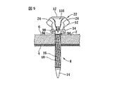
スリーブ22の各々の上方カラー66は、略環状形状の内側横断面を有し、その直径はファスナー胴部16の外径より僅かに大きいため、胴部16はスリーブ22内に所定の許容誤差範囲内で適合する。ある実施形態においては、図3に示されるように、上方カラー66は略八角形の外側横断面を有し、この形状は工具10のマガジン46の内側寸法に適合する。上方カラー66の内径は、ファスナー8の胴部16を摺動式に受容してしまり嵌めできる寸法を有する。上方カラー66は2つの半割72及び74を有し、これらの半割はスリーブ22を二分する破断面76にて互いに接合する。破断面76は、照合面50に垂直である。半割72及び74は破断面76に関して概ね対称である。上方カラー66の上面80は、互いに横方向反対側の2つのノッチ78を有する。ある実施形態においては、複数のノッチ78は略V字形状であり、上方カラー66の厚さに比べて比較的浅い。ノッチ78は、破断面76に概ね沿って配置され、ファスナーヘッド12に向かう背方向に開口する。従ってファスナー8がスリーブ22を通って打ち込まれたときに、スリーブ22を破断面76に沿って破壊することが容易になる。
The
中間部分70は、破断面76に関して互いに概ね対称な2つの壁82及び84を有する。中間部分70はまた、互いに横方向反対側の、2つの外側に開口する窓86を有する。図5に示されるように、これらの窓を通して胴部16の一部が見える。複数の窓86は、破断面76に沿って壁82と壁84との間に配置されるので、スリーブ22はその長さ方向に破断面76に沿って分割し続けることができる。壁82及び84は、図4に示されるように上方カラー66より狭いので、上方カラー66は、照合面50から横方向に延びる拡張部88を形成する。拡張部88は、照合ストリップ20をマガジン46に沿って案内するために使用可能な案内面90を有する。照合ストリップ20は、ファスナーヘッド12及び破壊可能な下方カラー68の上面100のような他の部材によっても、マガジン46に沿って案内可能である。
The
下方カラー68は比較的薄い複数のシェルフ92、厚めの台座94及び2つのタブ96を有する。下方カラー68は略環状形状の内側横断面を有する。この内側横断面は、上方カラー66の環状内側横断面と同じように、ファスナー8の胴部16を摺動式に把持する。シェルフ92の外側横断面も略環状形状であり、ファスナー8のヘッド12の直径に概ね等しい直径を有する。図2に示されるように、台座94及びタブ96は、シェルフ92から打ち込み方向に軸方向に延びる。
The
台座94は破断面76に沿って概ね整合配置され、複数のタブ96は照合面50に沿って概ね整合配置される。従って台座94は複数のタブ96に交差し、台座94及び複数のタブ96は、図7に示されるように十字又はプラス記号のような形状を形成する。台座94は、図7に示されるように孔64の直径よりも僅かに大きい幅を有するので、台座94はシェルフ92より実質的に狭い。孔64は台座94の中心を貫通する。複数のタブ96は台座94及び孔64によって、各々が台座94の各側に位置する2つの対称なタブ96に二分される。図2に示されるように、台座94及び複数のタブ96が軸方向にずらされて配置されるように、台座94は複数のタブ96よりもシェルフ92から遠く離れて軸方向に延びる。ある実施形態においては、台座94がシェルフ92から延びる距離は複数のタブ96がシェルフ92から延びる距離の約2倍である。
The
下方カラー68はまた、2つの大きな下方ノッチ98を、窓86におけるシェルフ92の上面100に有する。下方ノッチ98はV字形状である点で上方ノッチ78に類似するが、図2に示されるように下方ノッチ98の方が大きく、有意に深く下方カラー68内に延びる。従って下方ノッチ98はシェルフを貫通して台座94内に延びる。下方ノッチ98はまた、破断面76に概ね沿うように配置され、ファスナーヘッド12に向けて背方向に開口するので、上方ノッチ78及び下方ノッチ98の双方が破断面76に概ね沿って延びる。下方ノッチ98及び上方ノッチ78の双方は、スリーブ22を破断面76に沿って分割することを容易にするため、ファスナー8が工具10によって打ち込まれたときに、スリーブ22は実質的に等しい大きさでかつ略対称の2つのピース24に分断又は分割される。
The
照合ストリップ20は多くの異なる材料から形成可能であるが、十分な高密度を有する硬質ポリマーのような高分子樹脂材料から射出成形されることが好ましい。好適な樹脂は、約0.900g/cm3以上、好ましくは約0.925g/cm3以上、より好ましくは約0.945g/cm3以上の密度を有するポリエチレンのような高密度ポリオレフィンである。照合ストリップが脆く容易に破壊されることを防止するため、特に寒冷気候においては、照合ストリップ20は充填材を有さないポリオレフィンから成形されることが好ましい。高密度ポリオレフィンの射出成形等によって照合ストリップ20が形成された後に、ファスナー8がファスナー突部14を孔64に通すことによりスリーブ22内に配置される。従ってファスナーヘッド12は上方カラー66から背方向に向かい、ファスナー突部14は下方カラー68から打ち込み方向に向かう。
The
樹脂をファスナーから容易に分断するために、従来は照合ストリップに充填材が使用されるが、本発明の照合ストリップ20は実質的に充填材を有さないことが好ましい。それにより照合ストリップの破壊、又はマガジン46内での破断による工具10の故障が防止される。
(4) In order to easily separate the resin from the fastener, a filler is conventionally used in the verification strip, but it is preferable that the
照合ストリップ20の樹脂の構成が実質的に充填材を有さないときは、各々のスリーブ22のファスナー8からの分断がより困難になり、各々のスリーブ22が2つのピース24に容易に分割されるように構成されることが必要である。従来の照合ストリップにおいては、各々のスリーブの一部がファスナーヘッドと基材の表面との間に挟まれて潰されるため、ファスナーヘッドが基材の表面から離れたり、基材の表面から余りの樹脂が突き出たりしていた。上述したように外観は重要であることから、これらの状態は被覆の施工においては望ましくない。従って、ファスナーヘッド12と基材2の表面6との間にあるスリーブ22の部分をファスナーヘッド12が破壊する前に、スリーブ22をファスナー8から分断することが重要である。スリーブ22の形状は、上述のファスナー8のテーパを有する胴部16と同様に、スリーブ22の分断を補助する。
When the resin composition of the
工具10が点火する前に、照合ストリップ20はマガジン46内に配置され、マガジン46に沿って摺動して、1つのスリーブ22及びファスナー8を同時に工具10のノーズ部材32の中に送る。照合ストリップ20は、ノーズ部材32内に送られたスリーブ22及びファスナー8がバレル110内で位置決めされるように構成され、スリーブ22の中心軸58及びファスナー8はノーズ部材32の中心軸38に整合配置される。
Before the
マガジン46及びノーズ部材32は、スリーブ22がノーズ部材32内に適切な方向でのみ送られるように構成されるので、各々のスリーブ22の破断面76は常に同位置にあることが確保される。この方向は後述するように、ピース24が常に、ノーズ部材32の同位置においてファスナー8から排出されることを確保する。
The
マガジンフォロアー(図示せず)は照合ストリップ20をノーズ部材32に向けて付勢し、それによりファスナー8がノーズ部材32のバレル110内に位置決めされる。好ましくは、マガジンフォロアーは端スリーブ102の拡張部112の形状に適合する形状を有し、それによりマガジンフォロアーは、照合ストリップ20を支持するとともに照合ストリップ20の曲がり又は破壊を防止する。マガジンフォロアーの好適な実施形態は、本願の基礎出願と同時に出願された代理人番号13769号の継続出願に開示されている。この継続出願の開示内容はこの引用をもって本願明細書への記載に変える。
The magazine follower (not shown) urges the
ノーズ部材32は、工具10に対して延長位置及び引込位置に位置することができるように、工具10に接続される。ノーズ部材32は延長位置に向けて付勢され、工具10はノーズ部材32が引込位置にないときは起動できないように構成される。従って工具10は、工作物接触要素30が基材2に対して押圧されないときは点火できない。工具10を使用すべきときは、工作物接触要素30が基材2の所定の位置に押圧され、ノーズ部材32が引込位置に押し込まれる。
The
ノーズ部材32が引込位置に押し込まれると、ファスナー支持体(図示せず)がファスナー突部14に接するまで上方に押され、ファスナー8を所定位置に保持する。ノーズ部材32が完全に引き込められると、工具10が起動可能になり、ピストン及び推進ロッド37を打ち込み方向に駆動する。この操作は、推進ロッド37がファスナーヘッド12に衝突してファスナー8及びスリーブ22を打ち込み方向に推進し始めるまで続けられる。また工具10は、スリーブ22と照合ストリップの残部との間のブリッジ52及び54をきれいに分断する分断部材(図示せず)を有する。ファスナー支持体及び分断部材の実施例は、ITWケース番号13196号の特許出願「ファスナー駆動工具のためのテレスコープ式支持装置(Telescoping Support Device For Fastener Driving Tool)」に開示されている。この出願の開示内容はこの引用をもって本願明細書への記載に変える。
When the
ファスナー8が打ち込まれるときにファスナー8及びスリーブ22が経るステップは、図8〜図11に示される。ファスナー8は、ファスナーの胴部16がスリーブの孔64を通って摺動するように、スリーブ22よりも速く打ち込み方向に推進される。胴部16の直径は上述のテーパによって大きくなるので、胴部16はスリーブ22内で楔として作用し、破断面76に沿って力を生じさせる。最終的にはファスナーヘッド12の底面114がスリーブ22の上面80に接し、ファスナー8及びスリーブ22の双方がともに移動する。
Steps taken by the
ファスナー8及びスリーブ22は、台座94の底面26が基材2の表面6に接するまで打ち込み方向に推進され続ける。この点において、スリーブ22はそれ以上打ち込み方向に推進されないが、ファスナー8は基材2に打ち込まれ続ける。ラッパ形状のヘッド12が有するテーパ部116は楔として作用し、図9〜図11に示されるようにスリーブ22を破断面76に沿って2つのピース24に分断する。
The
ファスナー8は工具10によって打ち込み方向に推進され続け、ラッパ形状のヘッド12は、スリーブ22の分断により形成された2つのピース24の間に押し入り続ける。台座94はシェルフ92より狭いので、図10に示されるように、スリーブ22のピース24の各々はファスナー8から離れるように曲がり、シェルフ92が基材2に向けて曲がり始める。ファスナー8が打ち込み方向に推進されると、ファスナーヘッド12が複数のピース24を外側に押し、上述の曲がりによって複数のピース24はファスナー8から剥離される。複数の部材24は下方カラー68が分断し始める前から曲がり及び剥離可能であるので、大きめの下方ノッチ98はこの剥離を補助する。台座94が複数のタブ96からずらされることも、ファスナー8から離れるように複数のピース24を曲げることに役立つ。台座94は、ファスナー8から離れるように曲がる各々のピース24のためのピボットとして作用するからである。
The
ファスナーヘッド12は、下方ノッチ98において下方カラー68によって、スリーブ22を破断面76に沿って2つのピース24に分断し続ける。ファスナーヘッド12が基材2の表面6に打ち込まれると、図11に示されるように、スリーブ22は2つのピース24に完全に分割され、2つのピース24はファスナー8から外部に排出される。
The
上述のように、スリーブ22が一部たりともファスナーヘッド12と基材2との間に挟まれ潰されることはないことは重要である。ファスナーヘッド12が基材2の表面と同一高さになることが妨げられることがないからである。同様に、ファスナーヘッド12が表面6と同一高さになる適当な深さまで工具10がファスナー8を打ち込むことが重要である。支持部材4又は基材2の厚さは変更可能であるので、これらの厚さ変化、又はファスナー8の打ち込み深さに影響し得る他の全ての要因を補正するために工具10の打ち込み深さが調節可能であることは重要である。
As mentioned above, it is important that the
工具10のノーズ部材32は、ノーズ部材32に調節可能に接続される工作物接触要素30を有する。ある実施形態においては、工作物接触要素30は略円筒形状であり、自らの中心を通るバレル110を有する。工作物接触要素30は内表面20上にねじ118を有する。ねじ118はノーズ部材32の外表面124のねじ122に係合するため、ノーズ部材32は工作物接触要素30内に径方向に適合する。工具10の打ち込み深さは工作物接触要素30の回転によって調節される。この回転により、工作物接触要素30がノーズ部材32に対して軸方向に移動できるように工作物接触要素30のねじ118をノーズ部材のねじ122に係合させる。この移動は、打ち込み方向及び背方向のいずれにも可能であるが、ノーズ部材32及び工作物接触要素30の有効長を調節するために工作物接触要素30をどちらの方向に回転させるかに依存する。
The
打ち込み深さは、0.001インチ(又は0.025mm)の増分のような離散的間隔にて調節することが望まれる場合がある。離散的調節が望ましい理由は、作業者が工具10の打ち込み深さをどの程度調節したかを知ることができるからである。離散的調節を可能にするために、工作物接触要素30は、環状の弾性Oリング130を保持するための環状の溝126を外表面128に有する。溝126は、互いに等間隔配置された複数の孔132を有する。各々の孔132は工作物接触要素30を貫通し、ベアリング134を保持できる寸法を有する。ベアリング134は工作物接触要素30から、ノーズ部材32に向けて径方向内側に延びる。ノーズ部材32は等間隔に配置された複数のチャネル136を有する。複数のチャネル136は、ノーズ部材のねじ122を遮るように配置され、複数の孔132及びベアリング134に対応する。
It may be desirable to adjust the implant depth at discrete intervals, such as 0.001 inch (or 0.025 mm) increments. Discrete adjustment is desirable because it allows the operator to know how much the driving depth of the
工作物接触要素30及びノーズ部材32が組み立てられると、Oリング130は複数のベアリング134をノーズ部材32に向けて付勢する。第1の位置においては、工作物接触要素30は、ベアリング134がチャネル136内に配置される位置にある。工作物接触要素30が回転すると、複数の孔132がベアリング134をチャネル136から押し出す。次に工作物接触要素30は自由に回転可能になり、各々のベアリング134が次のチャネル136に会合するまで工作物接触要素30が回転する。工作物接触要素30が回転しているときは、Oリング130がベアリング134をノーズ部材32に向けて付勢し続けるので、各々のベアリング134がチャネル136に会合したときにベアリング134はチャネル136内に押される。ベアリング134がチャネル136内にあるときは、作業者はカチッという感触又は音(以降、クリックと称する)を感じ又は聞くことができる。この音は、工作物接触要素30がセット位置まで回転したことを示す。このようにして作業者は、工作物接触要素30を回転させて、工作物接触要素30がノーズ部材32に対してどの程度調節されたかを知ることができる。各々の位置は離散的距離に相当するからである。
When the
ある実施形態においては、図18に示されるように、工作物接触要素は約180°離れて配置された互いに反対側の2つの孔132を有する。2つのベアリング134が孔132に保持され、ノーズ部材32は約180°離れて配置された互いに反対側の2つのチャネル136を有する。工具10の打ち込み深さは、上述のように工作物接触要素30の回転によってノーズ部材32に対して調節可能である。約180°の半回転の各々によって、ベアリング134はあるチャネル136から反対側のチャネル136に移動し、作業者は上述の「クリック」を感知することができる。
In one embodiment, as shown in FIG. 18, the workpiece contact element has two opposing
しかし本発明は、互いに反対側の2つの孔を有する工作物接触要素に限定されるものではない。当業者には、隣接する孔から約120°離れて等間隔配置された3つの孔、同様に隣接するベアリングから約120°離れて等間隔配置された3つのベアリング、及び同様に隣接するチャネルから約120°離れて等間隔配置された3つのチャネルを有する工作物接触要素も、本発明の範囲内であることが理解されよう。同じ様に、4つ以上の等間隔配置された孔並びにそれらに対応するベアリング及びチャネルを有する工作物接触要素も、本発明の範囲内のものである。 However, the invention is not limited to a workpiece contact element having two opposing holes. One skilled in the art will recognize that three holes equally spaced about 120 ° from adjacent holes, three bearings equally spaced about 120 ° from adjacent bearings, and also from adjacent channels. It will be appreciated that a workpiece contact element having three channels equally spaced apart by about 120 ° is also within the scope of the present invention. Similarly, workpiece contact elements having four or more equally spaced holes and their corresponding bearings and channels are also within the scope of the present invention.
上述したように、ファスナー8が工具10によって打ち込み方向に推進されると、ファスナー8はスリーブ22を大きな力で複数のピース24に分断し、それらのピース24をファスナー8から排出できるようにする。スリーブ22が一部たりともファスナーヘッド12と基材2との間に挟まれて潰されないようにピース24がファスナー8からきれいに排出されることは好ましいが、高い打ち込み力の工具10には一般的であるように、ピース24が工具10から高速で制御されずに排出されることは望ましくない。ピース24がファスナー8から完全に分離されるが工具10から排出はされないように、新規かつ改良された工作物接触要素30及びノーズ部材32は、工具10からの排出を防止するための修正がなされる。
As described above, when the
上述したように、ノーズ部材32は工作物接触要素30内に径方向に係合するため、工作物接触要素30はノーズ部材32に対する自らの回転によって軸方向に調節可能である。従って、工作物接触要素30はノーズ部材32より大きい内径を有し、ノーズ部材32と同程度に有効にはスリーブ22及びファスナー8を案内できない。小さい直径のバレル110が工作物接触要素30を貫通していないからである。従ってノーズ部材32は打ち込み方向に可能な限り延び、工具10に打ち込まれるときのファスナー8を確実に案内することが望ましい。
As described above, the
ノーズ部材32がピース24のファスナー8からの分離に影響しないように、ノーズ部材32は、スリーブ22のピース24に対応するノーズ部材32の推進端部44に、互いに反対側の2つの窓138を有する。ある実施形態においては、図13に示されるように、各々の窓138は略矩形形状であるとともに、ピース24が窓138を通って容易に適合するような寸法を有する。窓138は、スリーブ22の破断面76に垂直な面に沿うようにノーズ部材32に配置されるので、ピース24は窓138を通って排出される。
To prevent the
ピース24が窓138を通って排出されるように各々のスリーブ22の破断面76を適切に整合配置するために、ノーズ部材32は開口部142を有する。それにより各々のスリーブ22は、ノーズ部材32を通ってバレル110内に適切な方向で送られる。開口部142は、スリーブ22及びファスナー8が一方向にのみ適合できるような形状を有するので、スリーブ22又はファスナー8が不適切に配置された場合はスリーブ22は開口部142を通って適合しない。開口部142は照合面50に概ね沿うように配置されるため、照合ストリップ20は開口部142内に送られる。窓138も照合面50に概ね沿うように配置されるため、スリーブ22が照合面50に垂直な破断面76に沿って分断されたときは、ピース24が窓138を通って排出される。スリーブ22及びファスナー8が適切に配置されているときは、それらは開口部142を通ってノーズ部材32のバレル110内を通過できる。
The
ピース24が工具10から排出されることを防止するために、工作物接触要素30が基材2に押し付けられている間、工作物接触要素30内に形成されたチャンバー140からピース24が排出されないように、工作物接触要素30が構成される。図16及び図17に示されるように、チャンバー140における工作物接触要素30の内径はチャンバー140内のノーズ部材32の外径より有意に大きい。上述のように工作物接触要素30は、工具10が点火される前に基材2に押し付けられて工具10に係合する必要がある。工作物接触要素30が基材2に押し付けられると、チャンバー140は一方向が基材2の表面6によって完全に塞がれ、他の全ての方向は工作物接触要素30によって塞がれる。工具10が点火されると、上述のようにピストンがファスナー8及びスリーブ22を打ち込み方向に推進し、ファスナー8がスリーブ22を2つのピース24に分割する。
To prevent the
複数のピース24は、工具10の力によってファスナー8から排出され、ノーズ部材32の窓138を通って、ノーズ部材32と工作物接触要素30との間のチャンバー140内に入る。ピース24は工作物接触要素30に当接するまで外側に移動し続ける。ピース24は重力によって140内に位置し、工作物接触要素30が基材2から引き離されるまで残存する。工具10が基材2から除去されると、ピース24はチャンバー140から自由に落下できる。
The
本発明の新規かつ改良された工作物接触要素30及びノーズ部材32は、ピース24が工具から高速で飛ぶことを防止するだけでなく、スリーブ22のピース24が落下する場所の制御にも役立つ。このようにして、作業者が本発明の工具10を使用した後に作業部位を清浄にすることが容易になる。ピース24は、予期せぬ方向に飛んでいく代わりに重力によって下方に落下するだけだからである。
The new and improved
本発明は上述の実施形態に限定されるものではなく、特許請求の範囲により限定される。 The present invention is not limited to the above embodiments, but is limited by the scope of the claims.
2…基材
8…ファスナー
10…工具
20…ストリップ
22…スリーブ
24…ピース
30…工作物接触要素
32…ノーズ部材
2.
Claims (10)
関連するファスナーの一部を受容し囲繞するための複数の接続されたキャリヤースリーブを備えたキャリヤーとを有し、
前記キャリヤースリーブの各々が軸と、脆い上方部分と、中間部分と、脆い下方部分と、該脆い下方部分に関連付けられて該脆い下方部分から軸方向に延びる台座と、前記関連するファスナーの前記ヘッドに向けて開口する、前記脆い下方部分内の第1の対のノッチとを有する、ファスナー組立体。 A plurality of fasteners arranged in a row each having a head and an elongated body,
A carrier with a plurality of connected carrier sleeves for receiving and surrounding a portion of an associated fastener;
Each of the carrier sleeves having a shaft, a fragile upper portion, a middle portion, a fragile lower portion, a pedestal associated with the fragile lower portion and extending axially from the fragile lower portion, and the head of the associated fastener. And a first pair of notches in the fragile lower portion that open toward the fastener assembly.
前記第1の対のノッチ及び前記第2の対のノッチは1つの平面内に配置され、
前記キャリヤースリーブの各々は、前記関連するファスナーが打ち込まれたときに前記平面に概ね沿う2つのピースに分割され、該ピースの各々は、前記台座上を回動しながら前記関連するファスナーから離れるように曲げられる、請求項1に記載のファスナー組立体。 Each of the carrier sleeves further has a second pair of notches in the fragile upper portion opening toward the head of the associated fastener;
The first pair of notches and the second pair of notches are located in one plane;
Each of the carrier sleeves is divided into two pieces that generally lie along the plane when the associated fastener is driven, and each of the pieces is pivoted on the pedestal and away from the associated fastener. The fastener assembly according to claim 1, wherein the fastener assembly is bent.
Applications Claiming Priority (1)
| Application Number | Priority Date | Filing Date | Title |
|---|---|---|---|
| US10/224,998 US6708821B2 (en) | 2002-08-21 | 2002-08-21 | Fastener collation strip and debris exhaust mechanism |
Publications (2)
| Publication Number | Publication Date |
|---|---|
| JP2004076946A true JP2004076946A (en) | 2004-03-11 |
| JP2004076946A5 JP2004076946A5 (en) | 2006-07-27 |
Family
ID=31187988
Family Applications (1)
| Application Number | Title | Priority Date | Filing Date |
|---|---|---|---|
| JP2003296132A Pending JP2004076946A (en) | 2002-08-21 | 2003-08-20 | Fastener assembly |
Country Status (7)
| Country | Link |
|---|---|
| US (2) | US6708821B2 (en) |
| EP (1) | EP1391616A3 (en) |
| JP (1) | JP2004076946A (en) |
| AU (1) | AU2003231725B2 (en) |
| CA (1) | CA2437930C (en) |
| NZ (1) | NZ527603A (en) |
| TW (1) | TWI236407B (en) |
Families Citing this family (33)
| Publication number | Priority date | Publication date | Assignee | Title |
|---|---|---|---|---|
| US7021462B2 (en) * | 2002-12-18 | 2006-04-04 | Powers Fasteners, Inc. | Fastener carrier assembly and method of use |
| US20040118720A1 (en) * | 2002-12-18 | 2004-06-24 | Powers Fasteners, Inc. | Fastener carrier assembly and method of use |
| FR2850895B1 (en) * | 2003-02-10 | 2006-03-03 | Prospection & Inventions | BAND OF FIXING ELEMENTS FOR SEALING APPARATUS WITH CHARGER FOR RECEIVING THE BAND, THE APPARATUS AND THE CHARGER |
| JP4239731B2 (en) * | 2003-07-04 | 2009-03-18 | マックス株式会社 | Contact mechanism of power driven nailer |
| JP4214967B2 (en) | 2004-02-06 | 2009-01-28 | マックス株式会社 | Part fixing tool and temporary holding mechanism for nailing machine of this part fixing tool |
| FR2869280B1 (en) * | 2004-04-26 | 2008-02-15 | Valeo Systemes Dessuyage | WIPER MECHANISM CONNECTOR FOR THE SIDE MOUNTING OF THE END OF AN ARM ON A WIPER BLADE |
| US7703649B2 (en) | 2004-05-04 | 2010-04-27 | Illinois Tool Works, Inc. | Collations for fasteners of various lengths |
| US7207761B2 (en) * | 2004-07-26 | 2007-04-24 | Illinois Tool Works Inc. | Pin fastener for achieving metal-to-metal connections |
| US20070193208A1 (en) * | 2006-02-22 | 2007-08-23 | Illinois Tool Works, Inc. | Embossed tape collating strip for nails |
| US7299961B2 (en) * | 2006-03-02 | 2007-11-27 | The Boeing Company | Device for controlled depth riveting |
| JP2007237328A (en) * | 2006-03-08 | 2007-09-20 | Hitachi Koki Co Ltd | Combustion type power tool |
| US7845888B2 (en) * | 2006-04-11 | 2010-12-07 | Illinois Tool Works Inc. | Scalloped tape collating strip for nails |
| US8333538B2 (en) * | 2006-05-12 | 2012-12-18 | Illinois Tool Works Inc. | Debris-free plastic collating strip for nails |
| US8360703B2 (en) * | 2006-05-12 | 2013-01-29 | Illinois Tool Works Inc. | Debris-free plastic collating strip for nails |
| US8152038B2 (en) * | 2007-03-16 | 2012-04-10 | Illinois Tool Works Inc. | Nose assembly for a fastener driving tool |
| US7513404B2 (en) | 2007-04-13 | 2009-04-07 | Illinois Tool Works Inc. | Depth of drive control with load transfer for fastener driver |
| US20080276563A1 (en) * | 2007-05-11 | 2008-11-13 | Anatoly Gosis | Stud attachment clip |
| US8220686B2 (en) * | 2007-07-17 | 2012-07-17 | Illinois Tool Works Inc. | Actuator pin guide for a fastener driving tool |
| JP2009264585A (en) * | 2008-03-31 | 2009-11-12 | Max Co Ltd | Connection fastener |
| US8251686B1 (en) | 2008-12-02 | 2012-08-28 | Illinois Tool Works Inc. | Apparatus for making debris-free nail collation |
| US8033005B1 (en) | 2008-12-02 | 2011-10-11 | Illinois Tool Works Inc. | Method for making debris-free nail collation |
| CN201389838Y (en) * | 2009-03-27 | 2010-01-27 | 张汉勤 | Nail-shooting launching device |
| US8556073B2 (en) * | 2010-11-02 | 2013-10-15 | Jaaco Corporation | Carriers for carrying fasteners for fastener driving tools |
| JP5701658B2 (en) * | 2011-03-31 | 2015-04-15 | 株式会社マキタ | Driving tool |
| FR3006933B1 (en) * | 2013-06-13 | 2015-12-04 | Illinois Tool Works | INDIRECT HOLD FIXING TOOL, PROPULSION MEMBER AND FIXING MEMBER HAVING THE SAME FOR THE TOOL, AND METHOD OF FASTENING A FASTENER |
| FR3009352B1 (en) * | 2013-08-01 | 2016-01-01 | Airbus Operations Sas | TOOLING FOR THE SIMULTANEOUS MAINTENANCE OF SEVERAL FASTENING CLIPS AGAINST AN AIRCRAFT FUSELAGE FRAME ELEMENT |
| FR3009274A1 (en) | 2013-08-01 | 2015-02-06 | Airbus Operations Sas | AIRCRAFT FUSELAGE FRAME ELEMENT INTEGRATING TABS FOR ATTACHING STIFFENERS |
| FR3009351B1 (en) * | 2013-08-01 | 2015-08-07 | Airbus Operations Sas | TOOLING FOR THE SIMULTANEOUS MAINTENANCE OF SEVERAL FASTENING CLIPS AGAINST AN AIRCRAFT FUSELAGE FRAME ELEMENT |
| ITUB20159529A1 (en) * | 2015-12-24 | 2017-06-24 | Fasco Srl | NAIL DEVICE FOR NAILS IN STICK |
| US10576616B2 (en) | 2018-05-07 | 2020-03-03 | Black & Decker Inc. | Power tool wire form hook assembly |
| US10766127B2 (en) * | 2018-05-07 | 2020-09-08 | Black & Decker Inc. | Nosepiece assembly with a passage for ejecting debris |
| CN109877782B (en) * | 2019-04-11 | 2024-06-25 | 浙江荣鹏气动工具股份有限公司 | Manual nailing gun for plastic steel nail arranging line clamp |
| WO2021211492A1 (en) * | 2020-04-15 | 2021-10-21 | Hkn International, Llc | Fastening system |
Citations (6)
| Publication number | Priority date | Publication date | Assignee | Title |
|---|---|---|---|---|
| JPS5481174U (en) * | 1977-11-21 | 1979-06-08 | ||
| JPS54117683U (en) * | 1978-02-06 | 1979-08-17 | ||
| JPS54119076U (en) * | 1978-02-09 | 1979-08-21 | ||
| JPS55115772U (en) * | 1979-02-08 | 1980-08-15 | ||
| JPS6446176U (en) * | 1987-09-11 | 1989-03-22 | ||
| JPH0352084U (en) * | 1989-09-21 | 1991-05-21 |
Family Cites Families (20)
| Publication number | Priority date | Publication date | Assignee | Title |
|---|---|---|---|---|
| DE2042768C3 (en) * | 1970-08-28 | 1981-01-29 | Hilti Ag, Schaan (Liechtenstein) | Magazine equipped with nails for a powder-powered setting tool |
| US4581964A (en) * | 1985-02-22 | 1986-04-15 | Max Co. Ltd. | Fastener driving tool with improved magazine and feed mechanism |
| JPH01150009A (en) * | 1987-12-07 | 1989-06-13 | Masaki Kawashima | Connector for fastener |
| DE4011778C2 (en) * | 1989-09-08 | 1995-06-01 | Hitachi Koki Kk | Pneumatic impact tool for fasteners |
| US5069340A (en) | 1991-03-05 | 1991-12-03 | Illinois Tool Works Inc. | Strip of collated fasteners for fastener-driving tool |
| DE4122873A1 (en) * | 1991-07-11 | 1993-01-14 | Hilti Ag | POWDER-POWERED SETTING UNIT WITH MAGAZINE FOR FASTENING ELEMENTS |
| US5197646A (en) * | 1992-03-09 | 1993-03-30 | Illinois Tool Works Inc. | Combustion-powered tool assembly |
| US5394268A (en) * | 1993-02-05 | 1995-02-28 | Carnegie Mellon University | Field synthesis and optical subsectioning for standing wave microscopy |
| US6055891A (en) * | 1993-02-17 | 2000-05-02 | Habermehl; G. Lyle | Exit locating screwdriver |
| US5320268A (en) * | 1993-04-13 | 1994-06-14 | Illinois Tool Works Inc. | Powered dimple-forming and fastener-driving tool |
| US5860580A (en) * | 1996-05-03 | 1999-01-19 | Illinois Tool Works Inc. | Piston retention device for combustion-powered tools |
| DE19707235A1 (en) * | 1997-02-24 | 1998-08-27 | Hilti Ag | Driving=in unit for fastening elements, such as nails, pins etc. |
| US5931622A (en) * | 1997-10-07 | 1999-08-03 | Illinois Tool Works Inc. | Fastener assembly with lateral end extension |
| US5836732A (en) | 1997-10-07 | 1998-11-17 | Illinois Tool Works, Inc. | Fastener assembly |
| US6145723A (en) * | 1998-01-27 | 2000-11-14 | Illinois Tool Works Inc. | Workpiece-contacting probe for fastener-driving tool for fastening dimpled membranes to foundation walls via fasteners and polymeric plugs |
| US6164510A (en) | 1998-06-03 | 2000-12-26 | Illinois Tool Works Inc. | Nosepiece shield for combustion powered tool |
| US5988477A (en) | 1998-06-03 | 1999-11-23 | Illinois Tools Works, Inc. | Nosepiece shield for combustion powered tool |
| US6394268B1 (en) * | 2000-09-29 | 2002-05-28 | Illinois Tool Works Inc. | Nail-type fastener collation strip with fastener guide rings, and combination thereof |
| US6641021B2 (en) * | 2002-03-25 | 2003-11-04 | Illinois Toolworks Inc. | Magazine rail system for fastener-driving tool |
| US6679412B1 (en) * | 2002-08-19 | 2004-01-20 | Illinois Tool Works Inc. | Stabilizing magazine follower for fastener driving tool |
-
2002
- 2002-08-21 US US10/224,998 patent/US6708821B2/en not_active Expired - Fee Related
-
2003
- 2003-05-23 US US10/444,314 patent/US6892922B2/en not_active Expired - Fee Related
- 2003-08-12 AU AU2003231725A patent/AU2003231725B2/en not_active Ceased
- 2003-08-14 NZ NZ527603A patent/NZ527603A/en not_active IP Right Cessation
- 2003-08-15 TW TW092122558A patent/TWI236407B/en not_active IP Right Cessation
- 2003-08-20 CA CA002437930A patent/CA2437930C/en not_active Expired - Fee Related
- 2003-08-20 JP JP2003296132A patent/JP2004076946A/en active Pending
- 2003-08-21 EP EP03292068A patent/EP1391616A3/en not_active Withdrawn
Patent Citations (6)
| Publication number | Priority date | Publication date | Assignee | Title |
|---|---|---|---|---|
| JPS5481174U (en) * | 1977-11-21 | 1979-06-08 | ||
| JPS54117683U (en) * | 1978-02-06 | 1979-08-17 | ||
| JPS54119076U (en) * | 1978-02-09 | 1979-08-21 | ||
| JPS55115772U (en) * | 1979-02-08 | 1980-08-15 | ||
| JPS6446176U (en) * | 1987-09-11 | 1989-03-22 | ||
| JPH0352084U (en) * | 1989-09-21 | 1991-05-21 |
Also Published As
| Publication number | Publication date |
|---|---|
| US6708821B2 (en) | 2004-03-23 |
| EP1391616A2 (en) | 2004-02-25 |
| US20040035901A1 (en) | 2004-02-26 |
| EP1391616A3 (en) | 2009-02-11 |
| NZ527603A (en) | 2004-07-30 |
| AU2003231725A1 (en) | 2004-03-11 |
| US6892922B2 (en) | 2005-05-17 |
| TW200414982A (en) | 2004-08-16 |
| TWI236407B (en) | 2005-07-21 |
| US20040035906A1 (en) | 2004-02-26 |
| CA2437930A1 (en) | 2004-02-21 |
| CA2437930C (en) | 2007-01-23 |
| AU2003231725B2 (en) | 2005-12-22 |
Similar Documents
| Publication | Publication Date | Title |
|---|---|---|
| JP2004076946A (en) | Fastener assembly | |
| EP0165674B1 (en) | Insert for a drywall | |
| US5069340A (en) | Strip of collated fasteners for fastener-driving tool | |
| JPH05321917A (en) | Fastener | |
| JP4234136B2 (en) | Fastener carrier assembly and usage | |
| JPH0610924A (en) | Improvement in concrete nail | |
| AU642288B2 (en) | Tapping screw | |
| US6814231B2 (en) | Strip of collated fasteners for fastener-driving tool | |
| US6679412B1 (en) | Stabilizing magazine follower for fastener driving tool | |
| JP4243503B2 (en) | Fixture driving tool magazine | |
| US11781583B2 (en) | Centering sleeve and fastening method | |
| US4041558A (en) | Sheetrock hole puncher and nail setter | |
| US6845693B1 (en) | Screw guide | |
| JP2002066950A (en) | Nailing machine | |
| AU2005232309B2 (en) | Fastener collation strip and debris exhaust mechanism | |
| NZ529189A (en) | Fastener collation strip and debris exhaust mechanism | |
| GB2275979A (en) | Anchorage for screws in plasterboard | |
| JP2005179913A (en) | Screw-in sleeve | |
| JP2001054880A (en) | Driving machine | |
| JPH08170620A (en) | Nail | |
| AU5200400A (en) | A screw guide |
Legal Events
| Date | Code | Title | Description |
|---|---|---|---|
| A521 | Written amendment |
Free format text: JAPANESE INTERMEDIATE CODE: A523 Effective date: 20060614 |
|
| A621 | Written request for application examination |
Free format text: JAPANESE INTERMEDIATE CODE: A621 Effective date: 20060614 |
|
| A131 | Notification of reasons for refusal |
Free format text: JAPANESE INTERMEDIATE CODE: A131 Effective date: 20090623 |
|
| A521 | Written amendment |
Free format text: JAPANESE INTERMEDIATE CODE: A523 Effective date: 20090924 |
|
| A131 | Notification of reasons for refusal |
Free format text: JAPANESE INTERMEDIATE CODE: A131 Effective date: 20100420 |
|
| A601 | Written request for extension of time |
Free format text: JAPANESE INTERMEDIATE CODE: A601 Effective date: 20100716 |
|
| A602 | Written permission of extension of time |
Free format text: JAPANESE INTERMEDIATE CODE: A602 Effective date: 20100722 |
|
| A02 | Decision of refusal |
Free format text: JAPANESE INTERMEDIATE CODE: A02 Effective date: 20101221 |