JP2004055152A - Sidelight type backlight device - Google Patents
Sidelight type backlight device Download PDFInfo
- Publication number
- JP2004055152A JP2004055152A JP2002206985A JP2002206985A JP2004055152A JP 2004055152 A JP2004055152 A JP 2004055152A JP 2002206985 A JP2002206985 A JP 2002206985A JP 2002206985 A JP2002206985 A JP 2002206985A JP 2004055152 A JP2004055152 A JP 2004055152A
- Authority
- JP
- Japan
- Prior art keywords
- guide plate
- light guide
- light
- mounting
- frame
- Prior art date
- Legal status (The legal status is an assumption and is not a legal conclusion. Google has not performed a legal analysis and makes no representation as to the accuracy of the status listed.)
- Withdrawn
Links
Images


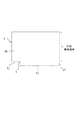
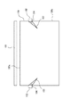
Landscapes
- Liquid Crystal (AREA)
- Planar Illumination Modules (AREA)
- Light Guides In General And Applications Therefor (AREA)
- Securing Globes, Refractors, Reflectors Or The Like (AREA)
Abstract
【課題】プリズム等の集光用凹凸を有する導光板とフレームとの取付構造を改善して、取付凸部を設けても輝線や暗部が生じないようにする。
【解決手段】一面2bに集光用凹凸が形成されているとともに一側端面2aが入光面とされた導光板本体20の他の側端面に取付凸部21が形成された導光板2と、取付凸部21によって前記導光板2が取り付けられるフレーム10とを備えたサイドライト型バックライト装置であって、前記取付凸部21は、前記入光面2aの対面2d側に形成されているとともに、当該対面以外の側端面2e,2fには非形成であり、さらに前記取付凸部21は、前記導光板本体20に対して段差が生じないように前記導光板本体20から突出している。
【選択図】 図2An object of the present invention is to improve a mounting structure between a light guide plate having condensed concavities and convexities such as a prism and a frame so that a bright line or a dark portion does not occur even when a mounting projection is provided.
A light guide plate (2) having a light guide plate (20) on one surface (2b) having concavo-convex concavities and a light incident surface on one side surface (2a) and a mounting protrusion (21) on the other side end surface of the light guide plate body (20). And a frame 10 to which the light guide plate 2 is mounted by the mounting protrusions 21. The mounting protrusions 21 are formed on the facing surface 2d side of the light incident surface 2a. At the same time, it is not formed on the side end surfaces 2e and 2f other than the facing surface, and the mounting projection 21 protrudes from the light guide plate main body 20 so that no step is formed with respect to the light guide plate main body 20.
[Selection] Fig. 2
Description
【0001】
【発明の属する技術分野】
本発明は、液晶表示装置等に用いられるサイドライト型バックライトに関するものである。
【0002】
【従来の技術】
サイドライト型バックライトは、導光板の側端面に光源を配置して構成されたものである。特開2000−214792号公報等に示すように、くさび形に形成された導光板の反射面にプリズム面を形成して集光効率を高めたものが公知である(以下、「従来技術1」という)。
また、プリズム面が形成されていない導光板の場合、導光板をフレームに取り付けるために、導光板の入光面と直交する両側端面に凸部を設けることが、特開平9−152557号によって公知である(以下、「従来技術2」という)。
【0003】
【発明が解決しようとする課題】
従来技術2の凸部を、従来技術1のようにプリズム面を有する導光板に適用すると次の問題が発生する。すなわち、図8に示すように、プリズム面を有する導光板100において、光源である冷陰極管101に対向する入光面100aと直交する両側端面100b,100cに凸部102,102を設けると、プリズムのために凸部102近傍に輝線103と暗部104が発生し、発光品位が低下する。
【0004】
輝線103と暗部104の発生を回避するため、従来は、プリズム面を有する導光板の場合、凸部102ではなく両面テープを利用してフレームへの取付けを行っていたが、両面テープも糊が光って異常発光し、液晶表示装置の狭額縁化等に対応するため、両面テープの幅は0.7〜2mm程度のものしか使用できず、接着面積が小さいことから組み立て作業が困難であって、接着力も十分確保できなかった。
本発明は、かかる事情に鑑みてなされたものであって、その課題は、プリズム等の集光用凹凸を有する導光板とフレームとの取付構造を改善することにある。
【0005】
【課題を解決するための手段】
本発明は、一面に集光用凹凸が形成されているとともに一側端面が入光面とされた導光板本体の他の側端面に取付凸部が形成された導光板と、取付凸部によって前記導光板が取り付けられるフレームとを備えたサイドライト型バックライト装置であって、前記取付凸部は、前記入光面の対面側に形成されているとともに、当該対面以外の側端面には非形成であり、さらに前記取付凸部は、前記導光板本体に対して段差が生じないように前記導光板本体から突出していることを特徴とする。
【0006】
本発明によると、従来技術2のような両面テープを用いなくとも取付凸部によって導光板を簡単にフレームに取り付けることができる。そして、導光板にプリズム等の集光用凹凸が形成されていても、入光面の対面側以外の側端面には取付凸部が形成されておらず、取付凸部が形成されていない面において輝線や暗部が発生することはない。そして、入光面の対面に形成されている取付凸部は、異常発光の原因となる段差が生じないように導光板本体に形成されているため、取付凸部を設けても発光品位低下が防止できる。
【0007】
また、前記取付凸部には前記集光用凹凸が非形成であるのが好ましい。取付凸部にも集光用凹凸が形成されていると、導光板をフレームに取り付けたときに当該集光用凹凸がフレームと接触することによって摩耗して悪影響を及ぼすことがあるが、取付凸部には集光用凹凸が非形成であれば、これを防止できる。
【0008】
さらに、前記取付凸部は、前記導光板本体からの突出量が当該取付凸部の他の部分に比べて少ない凹部分を有して、当該取付凸部の突出先端面が凹凸状に形成されており、前記凹部分の突出先端面は前記導光板の有効発光領域から0.5mm以上離れた位置にあるのが好ましい。取付凸部の突出先端面は、平坦面に限らず、フレームの形状に一致させる等のために凹凸面であってもよい。ただし、突出先端面が凹凸面であると凹凸のコーナ部で異常発光を生じ、異常発光が導光板の有効発光領域において生じると発光品位の低下となるため、凹部分であっても、突出先端面を有効発光領域から少なくとも0.5mm離しておくことで、異常発光が有効発光領域に生じることを防止できる。
【0009】
さらにまた、前記取付凸部の長手方向両端部には切欠部が形成されているのが好ましい。取付凸部の長手方向両端部に切欠部を形成しておくことで、フレームには、前記切欠部に対応した位置であるフレームコーナ部に補強部材を形成しておくことができ、フレームの強化を図ることができる。
【0010】
そして、前記取付凸部の長手方向両端部には、傾斜面が形成され、前記取付凸部の突出先端面と前記傾斜面とがなす内角は、異常発光を防止するため110゜以上180゜未満であるのが好ましい。
【0011】
【発明の実施の形態】
以下、本発明の好ましい実施形態を図面に基づいて説明する。図1は、フレームを除くバックライト装置1の主要構成部品を示しており、このバックライト装置は、液晶パネルの背後に配置される液晶表示装置用のものである。このバックライト装置は、光源としての冷陰極管1と、線状光源である冷陰極管1の光から面状の発光面2cを形成するための導光板2と、導光板発光面2cの反対側の反射面(非発光面)2bに配置された反射板3(シート状のものを含む)と、発光面2c側に配置された光学シート6,7とを備えている。また、導光板2等は後述のフレームに対して取付け固定される(詳細は後述)。
【0012】
前記冷陰極管1は、図示しないリフレクタ内に配置され、当該リフレクタによって冷陰極管1の光が効率よく導光板2に照射されるようになっている。
前記導光板2は、冷陰極管1と対向する一側端面2aが入光面とされており、入光面2aから導光板2内に進入した光は反射面2bにて反射され、発光面2cから面状の光となって出光する。
導光板2は、平面視において矩形状に形成されている。また、側面視においては、いわゆるくさび形に形成されており、入光面2a側が肉厚であり、当該入光面2aの対面2dに近づくにつれて薄肉となるように発光面2cと反射面2bとが非平行とされている。
【0013】
導光板反射面2bには、集光性の凹凸が形成されている。本実施形態では、集光性の凹凸としてプリズム面2bが形成されている。プリズム面2bを構成するプリズムは、断面形状が略二等辺三角形の三角条(突条)であり、条方向が入光面2a(冷陰極管1)に対して直交する方向に向いた三角条(突条)が複数本平行に設けられてプリズム面を構成している。なお、集光性の凹凸としてはプリズムに代えてレンチキュラーであってもよい。また、図1においてプリズム面2bの凹凸は強調して大きく描かれているが実際は微細な凹凸である。
導光板発光面2cには、輝度が発光面全体においてほぼ均一となるよう印刷またはシボ加工などにより構成された所定のパターンが施されている。
【0014】
前記反射板3は、ポリエチレンテレフタレートやポリカーボネート等の合成樹脂フィルムやアルミニウム等の金属薄膜により構成されたものであり、上記非発光面2b側の表面が白色に塗装されて構成されている。
前記光学シート6,7としては、プリズムシート6及び拡散シート7が設けられている。プリズムシート6は、略二等辺三角形の断面形状を有する三角状を複数設けたプリズム面を導光板2側に向けて下向きで配置されている。また、プリズムシート6は、条方向が入光面2a(冷陰極管1)と平行な方向に向くように配置されており、導光板2のプリズム面との相互作用によって効率的に集光することができる。図1においてプリズムシート6のプリズム面の凹凸は強調して大きく描かれているが実際は微細な凹凸である。
前記拡散シート7は、輝度が均一となるように光を拡散するためのものである。なお、光学シートとしては上記のものに限定されない。
【0015】
図2に示すように、前記導光板2は、集光性凹凸が形成された導光板本体20の他に、導光板本体20から突出した取付凸部21を備えている。この取付凸部21は、入光面2aの対面2d側においてのみ導光板本体20から0.5〜4mm(好ましくは1〜3mm)突出している。この取付凸部21は、バックライト装置のフレーム10に形成された溝状の受部11に差し込むためのものである(図3参照)。導光板2の取付凸部21を受部11に差し込むことで導光板2がフレーム10に取付け固定される。なお、導光板2は、反射板3とともに受部11に差し込まれる。また、取付凸部21と反射板3との重合範囲を利用して両面テープ等で導光板2と反射板3を接着して固定することができる。このため導光板2と反射板3との接着面積を広くとることができ、導光板2と反射板3の固定が安定化する。
【0016】
なお、受部11は、図3に示すように、取付凸部21が差し込み嵌合されて導光板2を固定するものであってもよいし、図4に示すように、フレーム10とフレーム10とは別体の固定板12とによって取付凸部21を挟み込んで固定する受部11であってもよい。ここで、固定板12は、ネジ・両面テープ等によってフレーム10に固定される。
【0017】
導光板本体20の反射面2bにはプリズム面が形成されているのに対し、取付凸部21の反射面2b側の面にはプリズム面(集光性凹凸)は形成されていない。取付凸部21にプリズム面が非形成であるため、フレーム10の受部11に差し込み等されても摩擦によって集光性凹凸が摩耗することが防止でき、摩耗による悪影響を回避できる。例えば、取付凸部21に集光性凹凸が形成されていると、フレーム10等との摩擦により集光性凹凸であるプリズムの頂角が丸くなる又は欠けることでその部分のブリズム機能が劣化し、これによりその部分が白濁して見えたり、異常発光で輝点に見えたりして発光面の均一性が損なわれ、発光品位が低下するが、取付凸部21に集光性凹凸を形成しないことでかかる問題を回避できる。
【0018】
集光性凹凸2bの有無を除き、前記取付凸部21は、発光面2c及び反射面2bと実質的に面一である。したがって、導光板2の厚さ方向にみて、導光板本体20と取付凸部21との境界Bには段差がない(図2(b)参照)。また、取付凸部21は、入光面2a及び対面2dと直交する側端面2e,2fと実質的に面一であり、導光板2の平面視において、導光板本体20と取付凸部21との境界Bには段差がない(図2(a)参照)。
取付凸部21が導光板本体20に対して段差なく突出しているため、段差による異常発光が生じない。また、他の側端面2a,2e,2fには従来技術2のような凸部がないため、凸部近傍においてプリズム面(集光性凹凸)による輝線と暗部の発生も生じない。
【0019】
取付凸部21を導光板本体20に対して段差なく突出させるやり方としては、図2以外に、図5に示すようにしてもよい。すなわち、導光板本体20の側端面2e,2fに対して、取付凸部21の横側端面2g,2hが段差なく傾斜していてもよい。横側端面2g,2hを傾斜させることで、取付凸部21の長手方向両端部に切欠部23が形成される。これらの切欠部23を設けておくことで、導光板2の周囲に位置する矩形状のフレーム10のコーナ部を肉厚にして強度を確保しつつ、当該フレーム10のコーナ部の肉厚部分を切欠部23に位置させて、フレームが大きくならないようにすることができる。フレーム10のコーナ部に肉厚部分を設けておくことで、フレーム10の他の部分を薄くしても十分な強度を確保でき、フレーム10のコーナ部肉厚部分は導光板2の切欠部23で吸収できるため、フレーム10の強度を確保しつつ狭額縁化を図ることができる。
【0020】
なお、取付凸部21の突出先端面2iと傾斜面2g,2hとがなす内角25は、異常発光を防止するため、比較的大きい方が好ましく、具体的には110゜以上180゜未満が好ましい。
【0021】
取付凸部21を導光板本体20に対して段差なく突出させる他のやり方としては、図6に示すものでもよい。すなわち、導光板本体20に対して取付凸部21全体が段差なく突出していれば、取付凸部21が突出先端面2iにおいて凹凸を含んでいてもよい。換言すると、突出先端面2iにおいて突出量が他の部分よりも少ない凹部分2j,2jがあってもよい。凹部分2j,2jは、切欠部23と同様に、フレーム10側の肉厚部分などの凸部分との干渉を避けるため等に形成される。
【0022】
凹部分2j,2jを形成する場合には、凹部分2j,2jにおける突出先端面が導光板2の有効発光領域(フレーム10によって覆われて実際には発光しない非有効発光領域を除く領域)から0.5mm以上離れている必要がある。換言すると、突出先端面2iに凹凸がある場合でも、取付凸部21自体は、対面2dの長手方向に連続して形成され、かつ有効発光領域からの突出幅Wは最低0.5mm確保される必要がある。凹部分2jの(角部)では、異常発光が生じる場合があるが、Wが0.5mm以上確保されているため、異常発光が生じても有効発光領域の発光品位低下を抑えることができる。なお、図6においては、導光板本体20のほぼ全体を有効発光領域として確保した場合の例を示している。
【0023】
図7は、比較例を示しており、取付凸部21が設けられているが、突出先端面2iに凹凸があり、しかも凹部分2jでは有効発光領域に対する突出幅がゼロである。この場合、凹部分2jの角部cにおいて異常発光が生じ、この異常発光が有効発光領域において生じるため発光品位が低下する。
【0024】
【発明の効果】
本発明によれば、導光板にプリズム等の集光用凹凸が形成されていても、入光面の対面側以外の側端面には取付凸部が形成されておらず、取付凸部が形成されていない面において輝線や暗部が発生することはない。そして、入光面の対面に形成されている取付凸部は、異常発光の原因となる段差が生じないように導光板本体に形成されているため、取付凸部を設けても発光品位低下が防止できる。
【図面の簡単な説明】
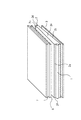
【図1】フレームを除くバックライト装置の分解斜視図である。
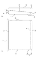
【図2】(a)は導光板の平面図であり、(b)は導光板の側面図である。
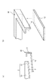
【図3】フレームと導光板の取付構造を示す断面図である。
【図4】(a)は、フレームと導光板の取付構造の他の例を示す断面図であり、(b)はフレーム分解斜視図である。
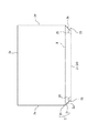
【図5】変形例に係る導光板の平面図である。
【図6】他の変形例に係る導光板の平面図である。
【図7】比較例に係る導光板の平面図である。
【図8】プリズム付導光板の両側端面に凸部を設けた場合に輝線及び暗部が生じる様子を示す平面図である。
【符号の説明】
1 光源
2 導光板
2a 入光面
2b 反射面(一面)
2d 対面
2e 側端面
2f 側端面
2g 傾斜面
2h 傾斜面
2i 突出先端面
2j 凹部分
10 フレーム
20 導光板本体
21 取付凸部
23 切欠部
25 内角[0001]
TECHNICAL FIELD OF THE INVENTION
The present invention relates to a sidelight type backlight used for a liquid crystal display device and the like.
[0002]
[Prior art]
The sidelight type backlight is configured by arranging a light source on a side end surface of a light guide plate. As shown in Japanese Patent Application Laid-Open No. 2000-214792 and the like, a light guide plate formed in a wedge shape and having a prism surface formed on a reflection surface thereof to increase the light collection efficiency is known (hereinafter, referred to as “prior art 1”). ).
Also, in the case of a light guide plate having no prism surface, it is known from Japanese Patent Application Laid-Open No. 9-152557 that, in order to attach the light guide plate to the frame, protrusions are provided on both end surfaces orthogonal to the light incident surface of the light guide plate. (Hereinafter referred to as “
[0003]
[Problems to be solved by the invention]
The following problem occurs when the convex portion of the
[0004]
Conventionally, in order to avoid the generation of the
The present invention has been made in view of such circumstances, and an object of the present invention is to improve an attachment structure between a light guide plate having concavo-convex light, such as a prism, and a frame.
[0005]
[Means for Solving the Problems]
The present invention provides a light guide plate in which a concavo-convex shape is formed on one surface and a mounting protrusion is formed on the other side end surface of the light guide plate main body in which one side end surface is a light incident surface, and a mounting protrusion. A sidelight-type backlight device including a frame on which the light guide plate is mounted, wherein the mounting protrusion is formed on a side facing the light incident surface, and is not provided on a side end surface other than the facing side. And wherein the mounting projection protrudes from the light guide plate body so that no step is formed with respect to the light guide plate body.
[0006]
According to the present invention, the light guide plate can be easily attached to the frame by the attaching protrusions without using a double-sided tape as in the
[0007]
Further, it is preferable that the concavo-convex unevenness is not formed on the mounting projection. If the concavo-convex projections are also formed on the mounting projections, when the light guide plate is attached to the frame, the converging projections may come into contact with the frame, causing wear and adverse effects. If the concavo-convex pattern is not formed on the portion, this can be prevented.
[0008]
Further, the mounting projection has a concave portion whose projection amount from the light guide plate main body is smaller than other portions of the mounting projection, and a protruding tip surface of the mounting projection is formed in an uneven shape. It is preferable that the protruding tip surface of the concave portion is located at a distance of 0.5 mm or more from the effective light emitting area of the light guide plate. The protruding tip surface of the mounting projection is not limited to a flat surface, but may be an uneven surface for conforming to the shape of the frame. However, if the protruding tip surface is uneven, abnormal light emission occurs at the corners of the unevenness, and if the abnormal light emission occurs in the effective light emitting area of the light guide plate, the light emission quality deteriorates. By keeping the surface at least 0.5 mm away from the effective light emitting region, it is possible to prevent abnormal light emission from occurring in the effective light emitting region.
[0009]
Furthermore, it is preferable that notches are formed at both ends in the longitudinal direction of the mounting projection. By forming notches at both ends in the longitudinal direction of the mounting projections, a reinforcing member can be formed at the frame corners at positions corresponding to the notches, so that the frame can be strengthened. Can be achieved.
[0010]
An inclined surface is formed at both ends in the longitudinal direction of the mounting projection, and an inner angle formed between the projecting tip surface of the mounting projection and the inclined surface is 110 ° or more and less than 180 ° to prevent abnormal light emission. It is preferred that
[0011]
BEST MODE FOR CARRYING OUT THE INVENTION
Hereinafter, preferred embodiments of the present invention will be described with reference to the drawings. FIG. 1 shows main components of the backlight device 1 except for a frame. The backlight device is for a liquid crystal display device disposed behind a liquid crystal panel. This backlight device includes a cold cathode tube 1 as a light source, a
[0012]
The cold cathode tube 1 is disposed in a reflector (not shown), and the light from the cold cathode tube 1 is efficiently irradiated on the
The
The
[0013]
Light-collecting plate irregularities are formed on the light guide
The light guide plate
[0014]
The
As the
The
[0015]
As shown in FIG. 2, the
[0016]
The receiving
[0017]
A prism surface is formed on the
[0018]
Except for the presence or absence of the
Since the mounting
[0019]
As a method for projecting the mounting
[0020]
The
[0021]
As another method of projecting the mounting
[0022]
In the case of forming the
[0023]
FIG. 7 shows a comparative example, in which the mounting
[0024]
【The invention's effect】
According to the present invention, even if the light guide plate is formed with condensing irregularities such as a prism, the mounting projection is not formed on the side end surface other than the side facing the light incident surface, and the mounting projection is formed. No bright line or dark portion is generated on the surface that has not been subjected. And since the mounting projection formed on the opposite surface of the light entrance surface is formed on the light guide plate main body so as to prevent the occurrence of a step which causes abnormal light emission, even if the mounting projection is provided, the light emission quality is deteriorated. Can be prevented.
[Brief description of the drawings]
FIG. 1 is an exploded perspective view of a backlight device excluding a frame.
FIG. 2A is a plan view of a light guide plate, and FIG. 2B is a side view of the light guide plate.
FIG. 3 is a cross-sectional view showing a mounting structure of a frame and a light guide plate.
FIG. 4A is a cross-sectional view illustrating another example of the mounting structure of the frame and the light guide plate, and FIG. 4B is an exploded perspective view of the frame.
FIG. 5 is a plan view of a light guide plate according to a modification.
FIG. 6 is a plan view of a light guide plate according to another modification.
FIG. 7 is a plan view of a light guide plate according to a comparative example.
FIG. 8 is a plan view showing a state in which bright lines and dark portions are generated when convex portions are provided on both end surfaces of the light guide plate with a prism.
[Explanation of symbols]
Reference Signs List 1
Claims (5)
前記取付凸部は、前記入光面の対面側に形成されているとともに、当該対面以外の側端面には非形成であり、
さらに前記取付凸部は、前記導光板本体に対して段差が生じないように前記導光板本体から突出していることを特徴とするサイドライト型バックライト装置。A light guide plate in which mounting projections are formed on the other side end surface of the light guide plate body on which light concavity and convexity are formed on one surface and one side end surface is a light incident surface, and the light guide plate is formed by the mounting projections. A sidelight type backlight device having a frame to be attached,
The mounting projection is formed on the side facing the light incident surface, and is not formed on a side end surface other than the facing side,
Further, the side projection type backlight device is characterized in that the mounting projection projects from the light guide plate main body so that no step is formed with respect to the light guide plate main body.
前記凹部分の突出先端面は前記導光板の有効発光領域から0.5mm以上離れた位置にあることを特徴とする請求項1又は2に記載のサイドライト型バックライト。The mounting protrusion has a concave portion whose protrusion amount from the light guide plate main body is smaller than other portions of the mounting protrusion, and a protruding tip surface of the mounting protrusion is formed in an uneven shape. ,
The sidelight type backlight according to claim 1, wherein the protruding front end surface of the concave portion is located at a distance of 0.5 mm or more from an effective light emitting area of the light guide plate.
前記取付凸部の突出先端面と前記傾斜面とがなす内角が110゜以上180゜未満であることを特徴とする請求項1〜4のいずれかに記載のサイドライト型バックライト。At both ends in the longitudinal direction of the mounting protrusion, an inclined surface is formed,
The sidelight type backlight according to any one of claims 1 to 4, wherein an inner angle formed between the projecting front end surface of the mounting projection and the inclined surface is 110 ° or more and less than 180 °.
Priority Applications (1)
| Application Number | Priority Date | Filing Date | Title |
|---|---|---|---|
| JP2002206985A JP2004055152A (en) | 2002-07-16 | 2002-07-16 | Sidelight type backlight device |
Applications Claiming Priority (1)
| Application Number | Priority Date | Filing Date | Title |
|---|---|---|---|
| JP2002206985A JP2004055152A (en) | 2002-07-16 | 2002-07-16 | Sidelight type backlight device |
Publications (1)
| Publication Number | Publication Date |
|---|---|
| JP2004055152A true JP2004055152A (en) | 2004-02-19 |
Family
ID=31931561
Family Applications (1)
| Application Number | Title | Priority Date | Filing Date |
|---|---|---|---|
| JP2002206985A Withdrawn JP2004055152A (en) | 2002-07-16 | 2002-07-16 | Sidelight type backlight device |
Country Status (1)
| Country | Link |
|---|---|
| JP (1) | JP2004055152A (en) |
-
2002
- 2002-07-16 JP JP2002206985A patent/JP2004055152A/en not_active Withdrawn
Similar Documents
| Publication | Publication Date | Title |
|---|---|---|
| KR101177909B1 (en) | Backlight assembly for Liquid Crystal display and Liquid Crystal Module using thereof | |
| US20030165067A1 (en) | Liquid crystal display and lighting unit used for the same | |
| US8339539B2 (en) | Illumination device and liquid crystal display device | |
| JPH10319400A (en) | Sidelight type surface light source device | |
| JP3322579B2 (en) | Sidelight type surface light source device | |
| US6419369B1 (en) | Sheet-like source light device and liquid crystal display device using the same | |
| EP3876027B1 (en) | Display device and surface light source | |
| JPH10112214A (en) | Sidelight type surface light source device | |
| JP2009093808A (en) | Illumination device and liquid crystal display device | |
| CN102549327A (en) | Illumination device, display device, and television receiving device | |
| US6199994B1 (en) | Surface light source device of side light type | |
| JP2004152496A (en) | Light guide plate | |
| JP2004319122A (en) | Light emitting device and method for relaxing lamp image in light emitting device | |
| JP4389529B2 (en) | Surface illumination device and light guide plate | |
| WO2011125242A1 (en) | Surface light source device and electronic device provided with same | |
| JP2002357823A (en) | Backlight for liquid crystal display | |
| JP4623613B2 (en) | Image display device and surface light source device | |
| JP3067717B2 (en) | Backlight | |
| JP2000214792A (en) | Backlight unit, backlight and space sheet used for it | |
| JP2002203422A (en) | Surface light source device and liquid crystal display device | |
| JP3421601B2 (en) | Light guide plate, surface light source device and display device using the light guide plate | |
| JP4084623B2 (en) | Backlight device for transmissive liquid crystal display element | |
| KR20010007415A (en) | surface light source device, liquid crystal display and reflecting member | |
| JP4165193B2 (en) | Backlight device | |
| JPH09269486A (en) | Surface light source device |
Legal Events
| Date | Code | Title | Description |
|---|---|---|---|
| A300 | Withdrawal of application because of no request for examination |
Free format text: JAPANESE INTERMEDIATE CODE: A300 Effective date: 20051004 |