JP2004054193A - Stereoscopic display without using spectacles - Google Patents
Stereoscopic display without using spectacles Download PDFInfo
- Publication number
- JP2004054193A JP2004054193A JP2002241212A JP2002241212A JP2004054193A JP 2004054193 A JP2004054193 A JP 2004054193A JP 2002241212 A JP2002241212 A JP 2002241212A JP 2002241212 A JP2002241212 A JP 2002241212A JP 2004054193 A JP2004054193 A JP 2004054193A
- Authority
- JP
- Japan
- Prior art keywords
- image
- eye
- angle
- louver
- observer
- Prior art date
- Legal status (The legal status is an assumption and is not a legal conclusion. Google has not performed a legal analysis and makes no representation as to the accuracy of the status listed.)
- Pending
Links
Images

Abstract
Description
【0001】
【発明の属する技術分野】
この発明は、右眼用映像と左眼用映像の分離にルーバーフィルムフィルタを用いた特殊眼鏡が不要な立体映像表示装置に関するものである。
【0002】
【従来の技術】
従来の特殊眼鏡が不要な立体映像装置として、イメージスプリッタを用いて1つの表示映像を右眼用映像と左目用映像に分離するパララックスバリア方式があった。
【0003】
【発明が解決しようとする課題】
これには、次のような欠点があった。
左右映像を縦分割し、間引きした上で、交互に並べてひとつの画像を用意する複雑な画像処理を要した。
また、映像の分割間引きにより横方向の映像情報量が1/2となり、高い画質が得られなかった。
本発明は、このような欠点を失くすためになされたものである。
【0004】
【課題を解決するための手段】
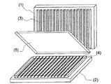
本発明では左眼用映像と右眼用映像の分離手段にルーバーフィルムフィルタ(3)(4)を用い、2つの映像表示装置(1)(2)にて左眼用映像と右眼用映像を独立表示せしめ、コンバイナ(5)でこれらを合成表示する。
以上の構成より成る立体表示装置である。
【0005】
【発明の実施の形態】
以下、本発明の実施の形態について説明する。
左眼用映像と右眼用映像を直角に配置した2つの映像表示装置(1)(2)に各々表示する。
これら2つの映像表示装置のどちらに左又は右眼用映像を表示するかは任意であるが、必ず片方が左眼用映像を映し、もう一方が右眼用映像を映す。
ルーバーフィルムフィルタ(3)(4)は各々映像表示装置(1)(2)の直前に置く。
映像表示装置(1)に左眼用映像を表示する場合にはルーバーフィルムフィルタ(3)のルーバー角度は観察者の左眼方向に設定し、ルーバーフィルムフィルタ(4)はこれと左右反対のルーバー角度を設定する。
映像表示装置(1)に右眼用映像を表示する場合にはルーバーフィルムフィルタ(3)のルーバー角度は観察者の右眼方向に設定し、ルーバーフィルムフィルタ(4)はこれと左右反対のルーバー角度を設定する。
ルーバーフィルムフィルタ(3)のルーバー角度の設定方法を図2に示す。
図2ではルーバー角度は観察者の左眼方向に設定されている。このため、観察者の左眼はルーバーフルムフィルタ(A)の裏側の映像表示装置(C)に表示される映像を見ることが出来るが、右眼の視線(E)はルーバー(B)に遮られて映像を見ることが出来ない。ルーバー角度(H)は観察者の両眼間の距離(F)と映像表示面から観察者の眼までの距離(G)により決まる可視側の視線の入る角度である。
このため、図2の通りルーバー角度は視線の入る角度に合わせて可視側の眼と反対側の端を最大角度とし、可視側の眼に近いほど小さくするとクロストークを少なく抑えられ理想的である。
ただし、ルーバーフィルムフィルタのコストを抑えるため、クロストーク性能の劣化が許容できる場合は、最大角度以下の範囲で全てのルーバーの角度を等しく揃えてもよい。
コンバイナに反射させる側の映像表示装置(2)に映す映像はコンバイナに投影されたときに正像として映るよう、左右反転処理する。
表示映像の上下方向は映像表示装置が直角を成す根元寄りを、上又は下にそろえる。
コンバイナは直角に配置した2つの映像表示装置(1)と(2)を二分する位置に45度の角度で取り付ける。
コンバイナの反射面は観察者側に向ける。
コンバイナは観察者側から見て50%の光を透過し、50%の光を反射するため2つの映像が重ねられる。
映像表示装置(1)の表示映像は、コンバイナ(5)を透過して観察者の眼に届くが、ルーバーフィルムフィルタ(3)の可視角度規制により、左眼もしくは右眼のいずれか片方にしか届かず、片方の眼には届かない。映像表示装置(1)の映像が届かない眼には、これに換わってコンバイナ(5)に投影された映像表示装置(2)の映像が見える。
映像表示装置(2)の映像も、これと対のルーバーフィルムフィルタ(4)により、可視角度が規制されており、この効果はコンバイナに映った後も失せないため、映像表示装置(1)が見える眼と逆の眼にのみ映像が届けられるのである。これらの結果、視差が生じ観察者は映像を立体として認知できる。
【0006】
【発明の効果】
本発明により、映像処理はコンバイナに投影する側の1つの映像のみ左右反転するだけで済むためシステムが簡単になる。
また、映像信号の間引きは左眼用、右眼用どちらの映像からも行わないため画質の劣化が少ない。
【図面の簡単な説明】
【図1】本発明品の斜視図
【符号の説明】
(1) 映像表示装置
(2) 映像表示装置
(3) ルーバーフィルムフィルタ
(4) ルーバーフィルムフィルタ
(5) コンバイナ
【図2】ルーバー角度の設定方法説明図
【符号の説明】
(A) ルーバーフィルムフィルタ
(B) ルーバー
(C) 映像表示装置
(D) 観察者の可視側の視線
(E) 観察者のルーバーに遮られた視線
(F) 観察者の両眼間の距離
(G) 映像表示面から観察者の眼までの距離[0001]
TECHNICAL FIELD OF THE INVENTION
The present invention relates to a three-dimensional image display device that does not require special glasses using a louver film filter for separating a right-eye image and a left-eye image.
[0002]
[Prior art]
As a conventional stereoscopic video apparatus that does not require special glasses, there has been a parallax barrier system in which one display video is separated into a right-eye video and a left-eye video using an image splitter.
[0003]
[Problems to be solved by the invention]
This has the following disadvantages.
A complicated image process was required in which the left and right images were vertically divided, thinned out, and alternately arranged to prepare one image.
Further, the amount of video information in the horizontal direction was reduced to に よ り by the thinning out of the video division, and high image quality could not be obtained.
The present invention has been made to eliminate such disadvantages.
[0004]
[Means for Solving the Problems]
In the present invention, louver film filters (3) and (4) are used as means for separating a left-eye image and a right-eye image, and a left-eye image and a right-eye image are displayed on two image display devices (1) and (2). Are displayed independently, and these are combined and displayed by the combiner (5).
This is a three-dimensional display device having the above configuration.
[0005]
BEST MODE FOR CARRYING OUT THE INVENTION
Hereinafter, embodiments of the present invention will be described.
The left-eye image and the right-eye image are respectively displayed on two image display devices (1) and (2) arranged at right angles.
Which of the two video display devices displays the left or right eye video is optional, but one always displays the left eye video and the other displays the right eye video.
The louver film filters (3) and (4) are placed immediately before the image display devices (1) and (2).
When displaying an image for the left eye on the image display device (1), the louver angle of the louver film filter (3) is set to the left eye direction of the observer, and the louver film filter (4) is a louver opposite to the left and right. Set the angle.
When displaying an image for the right eye on the image display device (1), the louver angle of the louver film filter (3) is set to the right eye direction of the observer, and the louver film filter (4) is a louver opposite to the left and right. Set the angle.
FIG. 2 shows a method for setting the louver angle of the louver film filter (3).
In FIG. 2, the louver angle is set to the left eye direction of the observer. Therefore, the left eye of the observer can see the image displayed on the image display device (C) behind the louver filter (A), but the line of sight (E) of the right eye is blocked by the louver (B). I can't see the video. The louver angle (H) is an angle at which a visual line of sight determined by the distance (F) between the eyes of the observer and the distance (G) from the image display surface to the eyes of the observer enters.
For this reason, as shown in FIG. 2, the louver angle is set to the maximum angle at the end opposite to the visible eye in accordance with the angle at which the line of sight enters. .
However, in order to reduce the cost of the louver film filter, if the deterioration of the crosstalk performance is acceptable, the angles of all the louvers may be equalized within the range of the maximum angle or less.
The image projected on the image display device (2) on the side to be reflected on the combiner is subjected to a left-right reversal process so that it is projected as a normal image when projected on the combiner.
In the vertical direction of the display image, the base where the image display device forms a right angle is aligned upward or downward.
The combiner is mounted at a 45 degree angle at a position where the two video display devices (1) and (2) arranged at right angles are bisected.
The reflective surface of the combiner faces the observer.
The combiner transmits 50% of the light as viewed from the observer side and reflects 50% of the light, so that two images are superimposed.
The display image of the image display device (1) passes through the combiner (5) and reaches the observer's eyes, but is restricted to only one of the left eye and the right eye due to the restriction of the viewing angle of the louver film filter (3). It does not reach and does not reach one eye. To the eyes to which the image of the image display device (1) does not reach, the image of the image display device (2) projected on the combiner (5) is seen instead.
The viewing angle of the image of the image display device (2) is also regulated by the paired louver film filter (4), and this effect cannot be lost even after being reflected on the combiner. The image is delivered only to the eye opposite to the visible eye. As a result, parallax occurs and the observer can perceive the image as a stereoscopic image.
[0006]
【The invention's effect】
According to the present invention, the system is simplified because only one image on the side to be projected on the combiner needs to be inverted left and right in the image processing.
Further, since the thinning of the video signal is not performed from either the left-eye video or the right-eye video, there is little deterioration in image quality.
[Brief description of the drawings]
FIG. 1 is a perspective view of a product of the present invention.
(1) Image display device (2) Image display device (3) Louver film filter (4) Louver film filter (5) Combiner [Fig. 2] Illustration of setting method of louver angle [Explanation of reference numerals]
(A) Louver film filter (B) Louver (C) Image display device (D) Visual line of sight of observer (E) Line of sight obstructed by louver of observer (F) Distance between observer's eyes ( G) Distance from image display surface to observer's eye
Claims (5)
Priority Applications (1)
| Application Number | Priority Date | Filing Date | Title |
|---|---|---|---|
| JP2002241212A JP2004054193A (en) | 2002-07-18 | 2002-07-18 | Stereoscopic display without using spectacles |
Applications Claiming Priority (1)
| Application Number | Priority Date | Filing Date | Title |
|---|---|---|---|
| JP2002241212A JP2004054193A (en) | 2002-07-18 | 2002-07-18 | Stereoscopic display without using spectacles |
Publications (2)
| Publication Number | Publication Date |
|---|---|
| JP2004054193A true JP2004054193A (en) | 2004-02-19 |
| JP2004054193A5 JP2004054193A5 (en) | 2005-07-28 |
Family
ID=31943983
Family Applications (1)
| Application Number | Title | Priority Date | Filing Date |
|---|---|---|---|
| JP2002241212A Pending JP2004054193A (en) | 2002-07-18 | 2002-07-18 | Stereoscopic display without using spectacles |
Country Status (1)
| Country | Link |
|---|---|
| JP (1) | JP2004054193A (en) |
Cited By (5)
| Publication number | Priority date | Publication date | Assignee | Title |
|---|---|---|---|---|
| WO2007122983A1 (en) * | 2006-04-17 | 2007-11-01 | Panasonic Corporation | Display device |
| JP2009031692A (en) * | 2007-07-30 | 2009-02-12 | National Institute Of Information & Communication Technology | Image display device |
| JP2013003323A (en) * | 2011-06-16 | 2013-01-07 | Kyodo Printing Co Ltd | Display member |
| WO2013031819A1 (en) * | 2011-08-30 | 2013-03-07 | 株式会社 スピン | Image projection device |
| US8665180B2 (en) | 2007-03-02 | 2014-03-04 | Nec Corporation | Image display device |
-
2002
- 2002-07-18 JP JP2002241212A patent/JP2004054193A/en active Pending
Cited By (9)
| Publication number | Priority date | Publication date | Assignee | Title |
|---|---|---|---|---|
| WO2007122983A1 (en) * | 2006-04-17 | 2007-11-01 | Panasonic Corporation | Display device |
| JPWO2007122983A1 (en) * | 2006-04-17 | 2009-09-03 | パナソニック株式会社 | Display device |
| US8189143B2 (en) | 2006-04-17 | 2012-05-29 | Panasonic Corporation | Display device |
| JP4950987B2 (en) * | 2006-04-17 | 2012-06-13 | パナソニック株式会社 | Display device |
| US8665180B2 (en) | 2007-03-02 | 2014-03-04 | Nec Corporation | Image display device |
| JP2009031692A (en) * | 2007-07-30 | 2009-02-12 | National Institute Of Information & Communication Technology | Image display device |
| JP2013003323A (en) * | 2011-06-16 | 2013-01-07 | Kyodo Printing Co Ltd | Display member |
| WO2013031819A1 (en) * | 2011-08-30 | 2013-03-07 | 株式会社 スピン | Image projection device |
| JPWO2013031819A1 (en) * | 2011-08-30 | 2015-03-23 | 株式会社スピン | Image projection device |
Similar Documents
| Publication | Publication Date | Title |
|---|---|---|
| US7440004B2 (en) | 3-D imaging arrangements | |
| KR100616556B1 (en) | Polarized stereoscopic display device and method without loss | |
| US20070085903A1 (en) | 3-d stereoscopic image display system | |
| JP4546505B2 (en) | Spatial image projection apparatus and method | |
| US5615046A (en) | Stereoscopic viewing system | |
| US6788274B2 (en) | Apparatus and method for displaying stereoscopic images | |
| JPH08205201A (en) | Pseudo stereoscopic vision method | |
| US5847870A (en) | Binocular stereo image display method | |
| KR20180076541A (en) | Floating hologram apparatus | |
| JPH07504766A (en) | Image forming system with two sets of screens | |
| KR100586221B1 (en) | 3-d image display device using flat display unit | |
| JP2004054193A (en) | Stereoscopic display without using spectacles | |
| JPH09224265A (en) | Method and device for recording stereoscopic image | |
| JP2004282217A (en) | Multiple-lens stereoscopic video image display apparatus | |
| KR20050076946A (en) | Display apparatus and method of three dimensional image | |
| Jones Jr et al. | VISIDEP (tm): visual image depth enhancement by parallax induction | |
| KR101093929B1 (en) | Method and system for displaying 3-dimensional images using depth map | |
| US20060152580A1 (en) | Auto-stereoscopic volumetric imaging system and method | |
| JP2004279743A (en) | Three dimensional display device | |
| CA2194630A1 (en) | Viewing system for electronic 3-d animation and 3-d viewing mirror | |
| WO2013031864A1 (en) | Display device | |
| KR20000039515A (en) | Display device for three dimensional image | |
| JPH09133891A (en) | Stereoscopic display device | |
| KR101866879B1 (en) | 3d optical filter for stereoscopic image display, and 3d apparatus using the same | |
| JP4254629B2 (en) | 3D image appreciation tool and 3D image appreciation system |
Legal Events
| Date | Code | Title | Description |
|---|---|---|---|
| A521 | Written amendment |
Free format text: JAPANESE INTERMEDIATE CODE: A523 Effective date: 20041220 |
|
| A621 | Written request for application examination |
Free format text: JAPANESE INTERMEDIATE CODE: A621 Effective date: 20041220 |
|
| A977 | Report on retrieval |
Free format text: JAPANESE INTERMEDIATE CODE: A971007 Effective date: 20060426 |
|
| A131 | Notification of reasons for refusal |
Free format text: JAPANESE INTERMEDIATE CODE: A131 Effective date: 20060516 |
|
| A02 | Decision of refusal |
Free format text: JAPANESE INTERMEDIATE CODE: A02 Effective date: 20060919 |