JP2004053154A - Air conditioner with air cleaner - Google Patents
Air conditioner with air cleaner Download PDFInfo
- Publication number
- JP2004053154A JP2004053154A JP2002212108A JP2002212108A JP2004053154A JP 2004053154 A JP2004053154 A JP 2004053154A JP 2002212108 A JP2002212108 A JP 2002212108A JP 2002212108 A JP2002212108 A JP 2002212108A JP 2004053154 A JP2004053154 A JP 2004053154A
- Authority
- JP
- Japan
- Prior art keywords
- air
- dust collecting
- electrode
- unit
- counter electrode
- Prior art date
- Legal status (The legal status is an assumption and is not a legal conclusion. Google has not performed a legal analysis and makes no representation as to the accuracy of the status listed.)
- Pending
Links
Images


Abstract
Description
【0001】
【発明の属する技術分野】
本発明は電気集塵方式の空気清浄装置を備えた空気調和機に係わり、より詳しくは、集塵部の気流抵抗を減少させ、送風機の負荷を低減し、かつ安全性、メンテナンスを向上させた空気清浄装置の構成に関する。
【0002】
【従来の技術】
従来の空気清浄装置付空気調和機は、例えば図1に示すようなものがある。図において、本体1の前面1aおよび上面1bのそれぞれに開閉パネル2a,2b を設けた吸込口3と前面下部に備える吹出口4とを結ぶ空気通路5に、前記吸込口3の裏面側に着脱自在に装着された網状のエアフィルタ12と、前後に分割して形成され逆V字形に折曲された上部熱交換器6と同上部熱交換器6の下部に連接する下部熱交換器7とでなる室内熱交換器8と、フレーム9に取付けられ、前記前面側上部熱交換器6の風上側に配置される空気清浄装置30と、送風機11とを配設している。また、前記前面側の開閉パネル2aは空気清浄装置30に対向する吸込口3aを塞がないようにしている。
そして、通常運転時は、前記開閉パネル2a,2b を開放した状態とし、吸込口3a4から吸込まれ空気清浄装置30を通過した空気と、通過しない空気を共に室内熱交換器8を通して調和し、同調和空気を送風機11により送風して吹出口4から室内に吹出すようにしている。
【0003】
また、従来の空気清浄装置には図4に示す特開平6−154651公報に記載されているように、空気清浄装置30は、空気流の上流側にコロナ放電部38を設け、下流側に集塵部41を設け、コロナ放電部38は、線状の放電電極36と平板状の対向電極37を設け、線状の放電電極36を電源34のマイナス側に、対向電極37を電源34のプラス側に接続するとともに接地35に接続している。
本例のコロナ放電部38は、負のコロナ放電を生じることにより、粒子に負の電荷を与えているが、必ずしもこの形状にとらわれる必要はなく、コロナ放電部38に進入した粒子に電荷を与えるものであればよい。
【0004】前記集塵部41は、空気流の上下流側にメッシュからなるガード電極39a,39b を設け、上流側ガード電極39a と下流側ガード電極39b の間にフィルタ40として誘電体繊維の不織布を一枚挟み込んでいる。そして、ガード電極39a,39b は電源34のプラス側に接続するとともに、接地35に接続されている。
ここで、ガード電極39a,39b はパンチングメタルなど通気性がありかつ導電性がある物であればよい。また、フィルタ40は誘電体スポンジや多孔質のセラミック、導体のスポンジ等、通気性があればよい。
【0005】上記構成において、その動作を説明する。空気流の上流側コロナ放電部38を通過することにより荷電された粒子は、空気の流れ方向のベクトル力に主たる支配を受けながら、下流側に進行し、やがて集塵部41の近傍に達する。ここで、集塵部41はガイド電極39a,39b とフィルタ40という開孔面の異なったものから構成されているので、この境界面において空気流は乱流場を生じ、粒子が上流側ガイド電極39a の導体近傍を通過る確率が整流の場合と比べて高まる。電荷が受ける力は距離の2乗に反比例するので、上流側ガイド電極39a の導体近傍を荷電粒子が過することにより荷電粒子が受けるクーロン力は高まり、粒子がガード電極39a に捕捉されることとなる。
【0006】
次に、上流側ガイド電極39a を通過した粒子はフィルタ40内部に進入し、フィルタ40にトラップされる。更にフィルタの最下流側と下流側ガード電極39b の境界面においては、ガイド電極39b とフィルタ40という開孔面の異なったものから構成されているので、この境界面において空気流は乱流場を生じ、粒子が下流側ガイド電極39b の導体近傍を通過する確率が整流の場合に比して高まり、上流側のガイド電極とフィルタ40の境界面で生じた同じプロセスによって集塵が行われる。
【0007】
また、図5は従来の空気清浄装置の組立構成図の一例を示したもので、放電電極36は、メーンフレーム51の枠部に設けられる絶縁ブロックに蛇行状に張設される。また、対向電極37は、その板面に放電電極36の間に位置する状態で複数の透孔52が所定間隔を存して設けられるアッパフレーム53に着脱自在に取着され、このアッパフレーム53は、メーンフレーム51に対して着脱自在に装着されている。
そして、対向電極37は、金属板を断面コ字状に折曲すると共に、その板面にはアッパフレーム53の透孔52に入り込む複数の電極部37a が内面側に切り起こされている。換言すれば、電極部37a 相互間に放電電極36が対向配置される。
前記集塵部41は、メーンフレーム51に対して着脱自在に装着される矩形状の枠体54に、帯状の多数の合成樹脂シート55が所定間隔で積層保持されている。枠体54の一側には把手54a が一体成形されている。
上記構成において、使用者は適宜期間毎に付着した塵埃を除去しなければならない。前記集塵部41は把手54a を持って引張り降ろすことによって、メーンフレーム51から容易に取外し可能な,ワンタッチ着脱ができる。
【0008】
しかしながら、上記従来の空気清浄装置30の構成の場合、図4に示すように、集塵部41はフィルタ40をガード電極39a,39b で挟み込んだ3層構造のため、気流抵抗が大きく、気流を発生させる送風機11の負荷が大きくなり、電力を多く消費するとともに、厚さが厚いためスペースが多く必要となる欠点がある。
また、図5に示すような組立構造の場合、集塵部41は容易に取外し、清掃することができるが、対向電極37に付着した塵埃を除去する場合、対向電極37の電極部37a がアッパフレーム53の透孔52に挿入されているため、集塵部41のようなワンタッチ着脱ができず、使用者にとって、取外しおよび取付け作業が極めて面倒である。また、コロナ放電部38でスパーク等が発生した場合の安全性及びメンテナンス性が不充分である。
【0009】
【発明が解決しようとする課題】
本発明は上記問題点に鑑みなされたもので、集塵部の気流抵抗を減少させ、送風機の負荷を低減し、かつ高圧電源部を独立させ脱着自在とすると共に、集塵部と対向電極の取外しを容易にして、安全性、メンテナンスを向上させた空気清浄装置付空気調和機を提供することを目的としている。
【0010】
【課題を解決するための手段】
本発明は上記課題を解決するためになされたもので、本体の前面上部備える吸込口と前面下部に備える吹出口とを結ぶ空気通路に、熱交換器と送風機を配設すると共に、前記吸込口の裏面側に着脱自在に装着された網状のエアーフルタと、同エアーフルタの後部に設けられ、空気流の上流側に放電電極に対向電極を対向してなるコロナ放電部と、下流側に集塵電極を備えた集塵部とから構成される電気集塵方式の空気清浄装置を設けてなる空気清浄装置付空気調和機において、
前記集塵部を集塵電極となる導電性の網状体により形成し、前記対向電極と同極性となるように、同対向電極の後面に着脱可能に配設してなる構成となっている。
【0011】
また、前記集塵部と前記対向電極とを磁石又は導電性バネにより接続してなる構成となっている。
【0012】
また、前記空気清浄装置を前記コロナ放電部と前記集塵部とからなる空気清浄ユニット本体と、前記放電電極と前記対向電極および前記集塵電極に高圧を供給する高圧電源ユニットと、同高圧電源ユニットに電力を供給する電源回路及び制御部を備えたメイン基板ユニットとから構成し、少なくとも前記空気清浄ユニット本体と前記高圧電源ユニットをコネクタにより挿脱自在に接続してなる構成となっている。
【0013】
また、前記高圧電源ユニットと前記メイン基板ユニットとを保護スイッチを介して電源線で接続し、前記保護スイッチを、前記エアフィルタを取り外した時OFF し、装着した時ONしてなる構成となっている。
【0014】
また、前記高圧電源ユニットと前記メイン基板ユニットに、夫々過電流遮断器を設け、前記空気清浄ユニット本体内でスパークが発生した時、前記高圧及び電力の供給を停止してなる構成となっている。
【0015】
また、前記コロナ放電部の前面に外部から手が触れないように保護カバーを設けてなる構成となっている。
【0016】
【発明の実施の形態】
以下、本発明における実施の形態を添付図面に基づいて詳細に説明する。
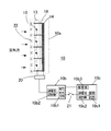
図1は本発明(従来例も同じ)による空気清浄装置付空気調和機の概略断面図、図2は本発明における空気清浄装置の構成図、図3は集塵部と対向電極の接続を示す要部拡大図で、(A)は磁石による方法、(B)はバネによる方法である。
【0017】
図において、本体1の前面1aおよび上面1bのそれぞれに開閉パネル2a,2b を設けた吸込口3と前面下部に備える吹出口4とを結ぶ空気通路5に、前記吸込口3の裏面側に着脱自在に装着された網状のエアーフルタ12と、前後に分割して形成され逆V字形に折曲された上部熱交換器6と同上部熱交換器6の下部に連接する下部熱交換器7とでなる室内熱交換器8と、フレーム9に取付けられ、前記前面側上部熱交換器6の風上側に着脱自在に装着される空気清浄装置10と、送風機11とを配設している。また、前記前面側の開閉パネル2aは空気清浄装置10に対向する吸込口3aを塞がないようにしている。
そして、通常運転時は、前記開閉パネル2a,2b を開放した状態とし、吸込口3aから吸込まれ空気清浄装置10を通過した空気と、通過しない空気を共に前記室内熱交換器8を通して調和し、同調和空気を前記送風機11により送風して吹出口4から室内に吹出すようにしている。
【0018】
前記空気清浄装置10は図2に示すように、空気清浄ユニット本体10a と、高圧電源ユニット10b 及びメイン基板ユニット10c とから構成されている。
前記空気清浄ユニット本体10a は、空気流の上流側にコロナ放電部13を設けると共に、下流側に集塵部14を設け、前記コロナ放電部13は、線状の放電電極15と平板状の対向電極16とが設けられ、前記線状の放電電極15と前記対向電極16との間に、前記高圧電源ユニット10b より高圧電圧が印加されている。そして、前記コロナ放電部13は印加電圧の極性により、正又は負のコロナ放電を生じることにより進入してきた粒子に電荷を与える。
【0019】
前記集塵部14は、集塵電極となる導電性の通気性がある1枚の網状体により形成され、前記集塵部14と前記対向電極16とが同極性となるように接続され、前記集塵部14が前記対向電極16の後面に着脱可能に装着されている。
これにより、集塵部14の気流抵抗を減少させ、送風機11の負荷を低減し、電力の消費を減少させ、集塵部14が薄くなることにより小型化が図れる。
【0020】
上記構成において、空気流の上流側の前記コロナ放電部13を通過することにより荷電された粒子は、空気の流れ方向のベクトル力に主たる支配を受けながら、下流側に進行し、やがて集塵部14の近傍に達する。電荷が受ける力は距離の2乗に反比例するので、集塵部14の導体近傍を荷電粒子が通過することにより荷電粒子が受けるクーロン力は高まり、粒子が集塵部14に捕捉されることとなる。
【0021】
図3は集塵部14と対向電極16の接続を示したもので、図3(A)は磁石を用いた方法で、複数の前記対向電極16は左右両端を帯状の桟16a で連結され、同両桟16a の上端裏面側に磁石18a が設けられ、枠体17に嵌め込まれるようになされている。一方、前記集塵部14は左右両端に帯状の桟14a が取付けられ、同両桟14a の上端表面側に磁石18b が設けられ、枠体17の下面に設けられた挿入孔17a より枠体17に挿入される構成となっている。この結果、前記集塵部14の挿入時に、前記磁石18a と磁石18b とが磁力により結合され、集塵部14と対向電極16とが同電極で接続される。
また、集塵部14の下端には把手14b が設けられ、この把手14b を持って引張り降ろすことによって、枠体17から容易に取外し可能な,ワンタッチ着脱ができ、簡単に清掃ができる。
【0022】
図3(B)は導電性のバネを用いた方法で、対向電極16の桟16a の上下左右両端に、上方に突出する導電性の板バネ20a が夫々設けられている。一方、集塵部14の桟14a の上下左右両端には、上方に突出し、内側へ屈曲する凸状のバネ20b が夫々設けられ、この集塵部14が枠体19に嵌め込まれるようになされている。この結果、前記対向電極16を上方より集塵部14に嵌合することにより、バネ20a とバネ20b とがバネ力により結合され、集塵部14と対向電極16とが同電極で接続される。
また、前記対向電極16を持ち上げることによって、集塵部14と対向電極16とを容易に分離することができる。
【0023】
また、図2に示すように、前記空気清浄装置10を前記空気清浄ユニット本体10a と、前記放電電極15と前記対向電極16および前記集塵部14に高圧を供給する、高圧発生回路10b1及び過電流遮断器10b2を備えた高圧電源ユニット10b と、同高圧電源ユニット10b に電力を供給する電源回路10c1、過電流遮断器10c2及び制御部10c3を備えたメイン基板ユニット10c とから構成し、少なくとも前記空気清浄ユニット本体10a と前記高圧電源ユニット10b とをコネクタ20により挿脱自在に接続してなる構成とすることにより、前記空気清浄ユニット本体10の清掃時や各ユニットの保守点検時に、夫々のユニットの取り外しが容易となり、メンテナンス性を向上することができる。
【0024】
また、前記空気清浄ユニット本体10a 内で塵の付着等により、スパークが発生し大電流が流れた場合、前記過電流遮断器10b2が作動し、前記空気清浄ユニット本体10a への高圧供給を停止すると同時に、前記高圧電源ユニット10b からの制御信号により、前記過電流遮断器10c2を作動させ、前記メイン基板ユニット10c から前記高圧電源ユニット10b への電力の供給を停止することにより、安全性を確保することができる。
【0025】
また、前記高圧電源ユニット10b と前記メイン基板ユニット10c とを保護スイッチ21を介して電源線で接続し、前記保護スイッチ21を、前記エアーフルタ12を取り外した時OFF し、装着した時ONする構成とすることにより、感電等による危険を防止し、安全性を確保することができる。
【0026】
また、図2に示すように、前記コロナ放電部13の前面に外部から手が触れないようにガードワイヤ22などからなる保護カバー(図示せず)を設けてなる構成とすることにより、上記と同様に、感電等による危険を防止し、安全性を確保することができる。
【0027】
以上に説明したように、前記集塵部14は、集塵電極となる導電性の通気性がある1枚の網状体により形成され、前記集塵部14と前記対向電極16とが同極性となるように接続され、前記集塵部14が前記対向電極16の後面に着脱可能に装着させることにより集塵部14の気流抵抗を減少させ、送風機11の負荷を低減し、電力の消費を減少させ、かつ、集塵部14の取り外しが容易となりメンテナンス性が向上し、また、集塵部14が薄くなることにより小型化が図れる。
更に、高圧電源ユニット10b を独立させ脱着自在とする共に、保護回路を設けることにより、安全性、メンテナンスを向上させた空気清浄装置付空気調和機となる。
【0028】
【発明の効果】
以上説明したように本発明においては、集塵部の気流抵抗を減少させ、送風機の負荷を低減し、かつ高圧電源部を独立させ脱着自在とすると共に、集塵部と対向電極の取外しを容易にして、安全性、メンテナンスを向上させた空気清浄装置付空気調和機となる。
【図面の簡単な説明】
【図1】本発明の空気清浄装置付空気調和機の側断面図である。
【図2】本発明の空気清浄装置の要部断面及び構成を示す図である。
【図3】本発明の集塵部と対向電極の接続を示す要部拡大図で、(A)は磁石による方法、(B)はバネによる方法である。
【図4】従来例の空気清浄装置の要部断面図である。
【図5】従来例の空気清浄装置の組立構成である。
【符号の説明】
1 空気調和機本体
2a,2b 開閉パネル
3 吸込口
4 吹出口
5 空気通路
6 上部熱交換器
7 下部熱交換器
8 室内熱交換器
9 フレーム
10 空気清浄装置
10a 空気清浄ユニット本体
10b 高圧電源ユニット
10b1 高圧発生回路
10b2,10c2 過電流遮断器
10c メイン基板ユニット
10c1 電源回路
10c3 制御
11 送風機
12 エアフィルタ
13 コロナ放電部
14 集塵部
14a,16a 桟
14b 把手
15 放電電極
16 対向電極
17,19 枠体
17a 挿入孔
18a,18b 磁石
20 コネクタ
20a,20b バネ
21 保護スイッチ
22 ガードワイヤ[0001]
TECHNICAL FIELD OF THE INVENTION
The present invention relates to an air conditioner provided with an air precipitator of an electric precipitating type, and more specifically, to reduce the airflow resistance of a precipitator, reduce the load on a blower, and improve safety and maintenance. The present invention relates to a configuration of an air cleaning device.
[0002]
[Prior art]
BACKGROUND ART A conventional air conditioner with an air purifier includes, for example, one shown in FIG. In the figure, an air passage 5 connecting an
During the normal operation, the open /
[0003]
Further, as described in Japanese Patent Application Laid-Open No. 6-154651 shown in FIG. 4, the conventional air cleaning device includes a
Although the
The dust collecting
Here, the
The operation of the above configuration will be described. The particles charged by passing the airflow through the upstream
[0006]
Next, the particles that have passed through the
[0007]
FIG. 5 shows an example of an assembly configuration diagram of a conventional air cleaning device. The
The
The
In the above configuration, the user must appropriately remove dust adhering to each period. The
[0008]
However, in the case of the configuration of the above-described conventional
Further, in the case of the assembly structure as shown in FIG. 5, the
[0009]
[Problems to be solved by the invention]
The present invention has been made in view of the above problems, and reduces the airflow resistance of the dust collector, reduces the load on the blower, makes the high-voltage power supply unit independent and makes it freely detachable, and provides the dust collector with the counter electrode. It is an object of the present invention to provide an air conditioner with an air purifying device that can be easily removed and has improved safety and maintenance.
[0010]
[Means for Solving the Problems]
The present invention has been made in order to solve the above-mentioned problem, and a heat exchanger and a blower are provided in an air passage connecting an intake port provided on an upper front portion of a main body and an outlet provided on a lower front portion of the main body. A mesh-shaped air filter detachably mounted on the back side of the air filter, a corona discharge section provided at the rear of the air filter and having a counter electrode facing the discharge electrode on the upstream side of the air flow, and a collector section on the downstream side. In an air conditioner with an air purifying device provided with an air purifying device of an electrostatic precipitating system comprising a dust collecting portion provided with a dust electrode,
The dust collecting portion is formed of a conductive mesh member serving as a dust collecting electrode, and is detachably provided on a rear surface of the counter electrode so as to have the same polarity as the counter electrode.
[0011]
Further, the dust collecting portion and the counter electrode are connected by a magnet or a conductive spring.
[0012]
An air purifying unit main body comprising the corona discharge unit and the dust collecting unit; a high voltage power supply unit for supplying a high voltage to the discharge electrode, the counter electrode and the dust collecting electrode; It is composed of a power supply circuit for supplying power to the unit and a main board unit provided with a control unit, and at least the air cleaning unit main body and the high-voltage power supply unit are removably connected by a connector.
[0013]
Further, the high-voltage power supply unit and the main board unit are connected by a power supply line via a protection switch, and the protection switch is turned off when the air filter is removed and turned on when the air filter is mounted. I have.
[0014]
Further, an overcurrent breaker is provided in each of the high-voltage power supply unit and the main board unit, and when a spark occurs in the air cleaning unit main body, the supply of the high voltage and the power is stopped. .
[0015]
In addition, a protective cover is provided so that the front surface of the corona discharge unit is not touched by an external hand.
[0016]
BEST MODE FOR CARRYING OUT THE INVENTION
Hereinafter, embodiments of the present invention will be described in detail with reference to the accompanying drawings.
FIG. 1 is a schematic cross-sectional view of an air conditioner with an air purifying device according to the present invention (the same applies to the conventional example), FIG. 2 is a configuration diagram of the air purifying device according to the present invention, and FIG. (A) is a method using a magnet, and (B) is a method using a spring.
[0017]
In the figure, an air passage 5 connecting an
During normal operation, the open /
[0018]
As shown in FIG. 2, the
The air cleaning unit
[0019]
The
Thereby, the airflow resistance of the
[0020]
In the above configuration, the particles charged by passing through the
[0021]
FIG. 3 shows the connection between the
A
[0022]
FIG. 3B shows a method using a conductive spring, in which conductive plate springs 20a protruding upward are provided at both the upper, lower, left and right ends of the
Further, by raising the
[0023]
As shown in FIG. 2, the
[0024]
When a large current flows due to the generation of sparks due to the adhesion of dust or the like in the air purifying unit
[0025]
Further, the high-voltage
[0026]
Further, as shown in FIG. 2, a protective cover (not shown) made of a
[0027]
As described above, the
Further, the high-voltage
[0028]
【The invention's effect】
As described above, in the present invention, the airflow resistance of the dust collection unit is reduced, the load on the blower is reduced, the high-voltage power supply unit is made independent and detachable, and the dust collection unit and the counter electrode can be easily removed. Thus, an air conditioner with an air purifier with improved safety and maintenance can be obtained.
[Brief description of the drawings]
FIG. 1 is a side sectional view of an air conditioner with an air cleaning device of the present invention.
FIG. 2 is a diagram showing a cross section and a configuration of a main part of the air cleaning device of the present invention.
FIG. 3 is an enlarged view of a main part showing a connection between a dust collecting part and a counter electrode of the present invention, wherein (A) is a method using a magnet and (B) is a method using a spring.
FIG. 4 is a sectional view of a main part of a conventional air cleaning device.
FIG. 5 is an assembly configuration of a conventional air cleaning device.
[Explanation of symbols]
DESCRIPTION OF
Claims (6)
前記集塵部を集塵電極となる導電性の網状体により形成し、前記対向電極と同極性となるように、同対向電極の後面に着脱可能に配設してなることを特徴とする空気清浄装置付空気調和機。A heat exchanger and a blower are disposed in an air passage connecting an intake port provided at an upper front portion of the main body and an outlet provided at a lower front portion, and a net-shaped air filter detachably mounted on the back side of the intake port. And a corona discharge unit provided at the rear of the air filter and having a counter electrode facing the discharge electrode on the upstream side of the air flow, and a dust collection unit provided with a dust collection electrode on the downstream side. In an air conditioner with an air purifier equipped with a dust collecting type air purifier,
The air is characterized in that the dust collecting portion is formed of a conductive mesh material serving as a dust collecting electrode, and is detachably disposed on a rear surface of the counter electrode so as to have the same polarity as the counter electrode. Air conditioner with cleaning device.
Priority Applications (1)
| Application Number | Priority Date | Filing Date | Title |
|---|---|---|---|
| JP2002212108A JP2004053154A (en) | 2002-07-22 | 2002-07-22 | Air conditioner with air cleaner |
Applications Claiming Priority (1)
| Application Number | Priority Date | Filing Date | Title |
|---|---|---|---|
| JP2002212108A JP2004053154A (en) | 2002-07-22 | 2002-07-22 | Air conditioner with air cleaner |
Publications (2)
| Publication Number | Publication Date |
|---|---|
| JP2004053154A true JP2004053154A (en) | 2004-02-19 |
| JP2004053154A5 JP2004053154A5 (en) | 2005-10-13 |
Family
ID=31935138
Family Applications (1)
| Application Number | Title | Priority Date | Filing Date |
|---|---|---|---|
| JP2002212108A Pending JP2004053154A (en) | 2002-07-22 | 2002-07-22 | Air conditioner with air cleaner |
Country Status (1)
| Country | Link |
|---|---|
| JP (1) | JP2004053154A (en) |
Cited By (4)
| Publication number | Priority date | Publication date | Assignee | Title |
|---|---|---|---|---|
| JP2007132610A (en) * | 2005-11-11 | 2007-05-31 | Hitachi Appliances Inc | Air conditioner |
| CN106839124A (en) * | 2017-03-30 | 2017-06-13 | 谢红卫 | The unidirectional new blower fan of plasma electrostatic depuration and operation method |
| CN106824537A (en) * | 2017-03-30 | 2017-06-13 | 谢红卫 | Plasma electrostatic depuration component and air cleaning facility |
| CN107166534A (en) * | 2017-06-13 | 2017-09-15 | 美的集团武汉制冷设备有限公司 | Air conditioner |
-
2002
- 2002-07-22 JP JP2002212108A patent/JP2004053154A/en active Pending
Cited By (6)
| Publication number | Priority date | Publication date | Assignee | Title |
|---|---|---|---|---|
| JP2007132610A (en) * | 2005-11-11 | 2007-05-31 | Hitachi Appliances Inc | Air conditioner |
| CN106839124A (en) * | 2017-03-30 | 2017-06-13 | 谢红卫 | The unidirectional new blower fan of plasma electrostatic depuration and operation method |
| CN106824537A (en) * | 2017-03-30 | 2017-06-13 | 谢红卫 | Plasma electrostatic depuration component and air cleaning facility |
| CN106824537B (en) * | 2017-03-30 | 2018-08-07 | 谢红卫 | Plasma electrostatic depuration component and air cleaning facility |
| CN106839124B (en) * | 2017-03-30 | 2022-03-18 | 谢红卫 | One-way plasma electrostatic purification fresh air machine and operation method |
| CN107166534A (en) * | 2017-06-13 | 2017-09-15 | 美的集团武汉制冷设备有限公司 | Air conditioner |
Similar Documents
| Publication | Publication Date | Title |
|---|---|---|
| KR950004657B1 (en) | Electric dust collector | |
| EP1219309B1 (en) | Air cleaner and its ionizing unit | |
| EP2318144B1 (en) | Apparatus, system, and method for enhancing air purification efficiency | |
| KR20040056135A (en) | Air purifier | |
| KR20160001203A (en) | Filter and air conditioner having the same | |
| EP1652587A2 (en) | Air conditioner with electrostatic dust collector | |
| JP2003071321A (en) | Electric dust collector and blower using the same | |
| JP2004053154A (en) | Air conditioner with air cleaner | |
| JP2004286418A (en) | Air filter | |
| KR101342101B1 (en) | Electric dust collector | |
| JP4354884B2 (en) | Air purifier, air purifier and air conditioner | |
| JP3976611B2 (en) | Ion removal apparatus and ion removal method | |
| JP3019961B2 (en) | Electric dust collector | |
| JP2004069212A (en) | Air conditioner with air cleaner | |
| JP3038757U (en) | Electric dust collection unit | |
| JP2662769B2 (en) | Air purifier | |
| JP2001179130A (en) | Air cleaner | |
| CN211987804U (en) | Electrostatic dust removal sterilizing air port purifying device easy to install and disassemble | |
| JP2001227766A (en) | Air conditioner | |
| CN213291928U (en) | Automobile air conditioner filtering system | |
| JP3630875B2 (en) | Air cleaner | |
| JP3577761B2 (en) | air purifier | |
| JP2001179127A (en) | Electric dust collector | |
| JPH03249961A (en) | Air cleaner | |
| JPH09150075A (en) | Air purifier |
Legal Events
| Date | Code | Title | Description |
|---|---|---|---|
| A521 | Request for written amendment filed |
Free format text: JAPANESE INTERMEDIATE CODE: A523 Effective date: 20050602 |
|
| A621 | Written request for application examination |
Free format text: JAPANESE INTERMEDIATE CODE: A621 Effective date: 20050603 |
|
| A977 | Report on retrieval |
Free format text: JAPANESE INTERMEDIATE CODE: A971007 Effective date: 20070411 |
|
| A131 | Notification of reasons for refusal |
Free format text: JAPANESE INTERMEDIATE CODE: A131 Effective date: 20070508 |
|
| A02 | Decision of refusal |
Free format text: JAPANESE INTERMEDIATE CODE: A02 Effective date: 20070911 |