JP2004044620A - Rack and pinion mechanism - Google Patents
Rack and pinion mechanism Download PDFInfo
- Publication number
- JP2004044620A JP2004044620A JP2002199359A JP2002199359A JP2004044620A JP 2004044620 A JP2004044620 A JP 2004044620A JP 2002199359 A JP2002199359 A JP 2002199359A JP 2002199359 A JP2002199359 A JP 2002199359A JP 2004044620 A JP2004044620 A JP 2004044620A
- Authority
- JP
- Japan
- Prior art keywords
- pinion
- rack
- swing arm
- axis
- support shaft
- Prior art date
- Legal status (The legal status is an assumption and is not a legal conclusion. Google has not performed a legal analysis and makes no representation as to the accuracy of the status listed.)
- Pending
Links
Images


Abstract
Description
【0001】
【発明の属する技術分野】
本発明は、バックラッシ抑制機能とセルフロック機能とを有するラック・ピニオン機構に関するものである。
【0002】
【従来の技術】
図5は、バックラッシ抑制機能を有する従来のラック・ピニオン機構の一例を示している。
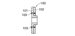
このラック・ピニオン機構におけるピニオン100は、図6に断面を示すように、主ピニオン部101と副ピニオン部102とを同軸状に重ね合わせた構成を有する。主ピニオン部101と副ピニオン部102は、主ピニオン部101に設けた長孔101aを貫通するボルト103によって互いの角度位相をずらした状態で結合されている。
【0003】
このラック・ピニオン機構によれば、上記主ピニオン部101と副ピニオン部102の位相ずれ量を適宜調整することによって、ピニオン100とラック104間のバックラッシを抑制することができる。
なお、ピニオン100を重ね合せ構造にする代わりに、ラック104を重ね合せ構造にすることも可能である。
【0004】
図7は、テーパギヤ200と、このテーパギヤ200に噛合うラック201とを備えたラック・ピニオン機構を示している。このようなラック・ピニオン機構においては、テーパギヤ200の軸方向位置を調整することによってバックラッシを抑制することができる。
【0005】
【発明が解決しようとする課題】
図5に示したラック・ピニオン機構は、主ピニオン部101と副ピニオン部102とを重ね合せた特殊な構造のピニオン100を必要とする。つまり、汎用のピニオンを用いることができないという欠点がある。
また、上記ピニオン100の厚みが大きくなるので、機構全体が大型化するという不都合も生じる。
もちろん、主ピニオン部101と副ピニオン部102の厚さを小さくすれば、上記の不都合は回避することができる。しかし、上記構成のピニオン100は、主ピニオン部101と副ピニオン部102のいずれか一方のみが動力の伝達に寄与することになるので、それらの厚さを小さくすると、動力伝達容量が減少して許容負荷が小さくなる。
【0006】
このラック・ピニオン機構には、次のような問題点もある。すなわち、図5に示した主ピニオン部101と副ピニオン部102には、ピッチ高さのばらつき等の加工誤差が存在し、また、ラック104にもピッチ高さのばらつきや、曲がり等が存在する。
したがって、ラック104のある位置でのバックラッシが抑制されるように上記ピニオン100における主ピニオン部101と副ピニオン部102の位相差を調整しても、他の位置でのバックラッシが抑制される保証はなく、場合によっては、他の位置でマイナスバックラッシを生じて、機構自身が円滑に作動しなくなる虞もある。
【0007】
一方、図7に示したラック・ピニオン機構は、テーパギヤ200の位置調整に手間を要する。また、このラック・ピニオン機構は、上記テーパギヤ200に加工誤差が存在するとともに、ラック201にも加工誤差や曲がり等が存在することから、ある位置でのバックラッシが抑制されるように上記テーパギヤ200の軸方向位置を調整しても、他の位置でのバックラッシが抑制されない虞がある。
【0008】
本発明の目的は、このような状況に鑑み、特殊な構造のピニオンや、ピニオンの軸方向位置の調整を必要とすることなく、かつ、ピニオンおよびラックの加工誤差等の影響を受けることなくバックラッシを抑制することができ、しかも、セルフロック機能を併せて得ることができる実用性の高いラック・ピニオン機構を提供することにある。
【0009】
【課題を解決するための手段】
本発明に係るラック・ピニオン機構は、ピニオンを支持するとともに、このピニオンの中心軸線に平行する支軸によって揺動可能に支持され、前記ピニオンをラックに当接させたときに、前記支軸と前記ピニオンの軸とを結ぶラインが前記ラックの軸線に直行する面に対して所定の角度をなすように配設されたスイングアームと、前記ピニオンによって前記ラックが与圧されるように前記スイングアームを付勢するバネ要素と、を備えることを特徴としている。
【0010】
好ましい実施の形態においては、前記スイングアームの支軸の軸線の延長上に軸線が位置された駆動ギヤと、前記ピニオンの軸に取り付けられて前記駆動ギヤと噛み合う従動ギヤとを更に設け、前記駆動ギヤの動力を前記従動ギヤを介して前記ピニオンに伝達するように構成している。
【0011】
【発明の実施の形態】
以下、図面を参照して本発明に係るラック・ピニオン機構の好ましい実施の形態について説明する。
図1は、本発明に係るラック・ピニオン機構の斜視図である。図2は、図1に示すケーシング1の前壁1aを除いて示した内部機構図、図3は図2のA−A断面図である。
【0012】
この実施の形態に係るラック・ピニオン機構は、ケーシング1の前壁1aの内面に支軸2を突設し、この支軸2の先端部にスイングアーム3の略中央部を回動可能に支持させてある。なお、図3において、符号4は、支軸2とスイングアーム3との間に介在させた軸受である。
【0013】
スイングアーム3は、その下端部に設けた軸受5を介して駆動軸6を回動可能に支持している。駆動軸6は、上記支軸2に平行するように設けられ、その一端部にピニオン7を形成するとともに、その他端部に従動ギヤ8を取り付けてある。
上記ピニオン7は、ラック9と噛合っている。また、上記従動ギヤ8は、モータ10の出力軸に取り付けられた駆動ギヤ11と噛合っている。
【0014】
ラック9は、ケーシング1の底壁1b上に設けられたガイド部材12によってガイドされて、図2における左右方向に移動することができる。
上記モータ10は、その出力軸の軸線(ギヤ11の軸線)が上記支軸2の軸線の延長上に位置するようにケーシング1の後壁1cに取り付けられている。
【0015】
図2に示すように、ケーシング1の上壁1dには、バネ受け部材13が設けられ、このバネ受け部材13とスイングアーム3の上側端部との間に反発バネ14が介在されている。スイングアーム3は、この反発バネ14の弾性力によって、図2における反時計回り方向に付勢されている。
【0016】
次に、上記構成を有する本発明に係るラック・ピニオン機構の作用について説明する。
上記スイングアーム3は、支軸2を中心として揺動可能である。図4には、ピニオン7がラック9に当接したときのスイングアームの姿勢が実線で示されている。
この図4に示すように、スイングアーム3は、ピニオン7がラック9に当接した際に、支軸2とピニオン7の軸とを結ぶラインが前記ラックの軸線に直行する面に対して所定の角度θをなすようにその腕長(上記ラインの長さ)が設定されている。
したがって、例えば、スイングアーム3が実線で示す位置から鎖線で示す位置まで揺動した場合には、ピニオン7の中心点が位置P1から位置P2まで移動すること、つまり、下方にLだけ変位することになる。
【0017】
スイングアーム3は、バネ14の反発力で図2における反時計回り方向に付勢されている。それゆえ、ピニオン7は、バネ14の弾性力によってラック9に圧接することになる。換言すれば、ラック9はピニオン7によって与圧されることになる。
上記したように、スイングアーム3によって支持されたピニオン7は、支軸2と該ピニオン7の軸とを結ぶラインを半径とする円周に沿って変位可能である。したがって、上記与圧は、ラック9のピッチ平面方向だけでなく、ピニオン7とラック9の軸平面方向にも作用する。
【0018】
モータ10が作動すると、その回動力が駆動ギヤ11、従動ギヤ8および駆動軸6を介してピニオン7に伝達されるので、ラック9がガイド部材12でガイドされながら図2における左右方向に駆動される。
このとき、ラック9は、常時ピニオン7によって上記ピッチ平面方向および軸平面方向に与圧されるので、たとえピニオン7およびラック9にピッチ高さのばらつき等の加工誤差が存在していたとしても、また、それらの組み付け精度が低い場合でも、バックラッシを伴うことなく円滑に作動される。
【0019】
ところで、上記したように、上記モータ10の出力軸の軸線(駆動ギヤ11の軸線)は、支軸2の軸線の延長上に位置されている。したがって、スイングアーム3が揺動した場合、従動ギヤ8の中心が駆動ギヤ11の軸線を中心とする所定の円周上を移動することになる。これは、スイングアーム3が揺動しても両ギヤ8,11の噛合い状態が良好に維持されることを意味している。
【0020】
上記ラック・ピニオン機構は、バネ14の強さを変更することによって、ロストモーションを適切に調整することができる。もちろん、バネ14の強さは、モータ10の出力から換算されるラック9の推力を阻害しない大きさに設定される。
なお、上記スイングアーム3は、ラックの動作や負荷の状態変化に応じて図2に示す状態から反時計回り方向(バネ14を圧縮する方向)に揺動することがある。そして、この揺動の程度によっては、ピニオン7とラック9の噛合い状態が解かれることがあり得る。そこで、この実施の形態では、ピニオン7とラック9の噛合い状態が解かれる前にスイングアーム3の上端部を当接させる揺動停止用のストッパ15をケーシング1の上壁1dに設けてある。
【0021】
次に、セルロック機能について説明する。図2において、ラック9に右方向の外力が加わると、スイングアーム3に反時計回り方向の回転力が発生して、ピニオン7がラック9に強く圧接して該ラック9をロックする。つまり、ピニオン7がラック9に対する楔としての働きをするので、ラック9がロックされて該ラック9の位置が保持されることになる。
【0022】
このように、この実施の形態に係るラック・ピニオン機構によれば、ピニオン7の楔作用に基づくセルフロック機能が得られる。したがって、図2におけるラック9の右端部が下方に向く態様で設置すれば、モータ10の状態や従動ギヤと駆動ギヤ11からなる減速要素の状態によらず、ラック9の落下が確実に防止される。
上記ラック9のロック作用は、該ラック9に加えられる所定の一方向の外力によって発生するものであって、モータ10の動力伝達系をロックするものではない。したがって、モータ10を正逆転させれば、ラック9を円滑に往復動作させることができる。
なお、上記のように、図2におけるラック9の右端部が下方に向く態様で設置すれば、ラック9を外力で上昇させる操作を行うことによって、該ラック9の位置を調整することができる。
【0023】
【発明の効果】
本発明に係るラック・ピニオン機構によれば、ピニオンによってラックが与圧されるので、ピニオンおよびラックにピッチ高さのばらつき等の加工誤差が存在していたとしても、また、それらの組み付け精度が低い場合でも、バックラッシを抑制して円滑にラックを往復動させることができる。
また、セルフロック機能を有するので、ラックが下方向の外力の作用でロックされるように設置して使用すれば、このラックの落下を防止することが可能である。しかも、上記のように設置すれば、ラックを外力で上昇させる操作を行うことによって、該ラックの位置を調整することができる。
加えて、本発明に係るラック・ピニオン機構によれば、特殊な構成のピニオンを必要とせず、かつ、ピニオンの軸方向位置の調整も必要としない。
【図面の簡単な説明】
【図1】本発明に係るラック・ピニオン機構の実施の形態を示す斜視図である。
【図2】ケーシングの前壁を除いて示したラック・ピニオン機構の内部構成図である。
【図3】図1のA−A断面図である。
【図4】ピニオンの変位形態を示す模式図である。
【図5】従来のラック・ピニオン機構の一例を示す概念図である。
【図6】図5に示すラック・ピニオン機構におけるピニオンの断面図である。
【図7】従来のラック・ピニオン機構の他の例を示す概念図である。
【符号の説明】
1 ケーシング
2 支軸
3 スイングアーム
6 駆動軸
7 ピニオン
8 従動ギヤ8
9 ラック
10 モータ
11 駆動ギヤ
12 ガイド部材
13 バネ受け部材
14 バネ
15 ストッパ[0001]
TECHNICAL FIELD OF THE INVENTION
The present invention relates to a rack and pinion mechanism having a backlash suppression function and a self-locking function.
[0002]
[Prior art]
FIG. 5 shows an example of a conventional rack and pinion mechanism having a backlash suppression function.
The
[0003]
According to the rack and pinion mechanism, the backlash between the
Note that instead of the
[0004]
FIG. 7 shows a rack and pinion mechanism including a
[0005]
[Problems to be solved by the invention]
The rack and pinion mechanism shown in FIG. 5 requires the
Further, since the thickness of the
Of course, if the thicknesses of the
[0006]
This rack and pinion mechanism also has the following problems. That is, the
Therefore, even if the phase difference between the
[0007]
On the other hand, the rack and pinion mechanism shown in FIG. 7 requires time and effort to adjust the position of the
[0008]
In view of such circumstances, an object of the present invention is to provide a backlash without requiring a pinion having a special structure or adjusting the axial position of the pinion, and without being affected by processing errors of the pinion and the rack. Another object of the present invention is to provide a highly practical rack-and-pinion mechanism that can suppress the occurrence of a self-locking function.
[0009]
[Means for Solving the Problems]
The rack and pinion mechanism according to the present invention supports the pinion, is swingably supported by a support shaft parallel to the center axis of the pinion, and when the pinion abuts on the rack, the support shaft and the pinion A swing arm disposed so that a line connecting the axis of the pinion is at a predetermined angle with respect to a plane perpendicular to the axis of the rack; and the swing arm such that the rack is pressurized by the pinion. And a spring element for biasing the spring.
[0010]
In a preferred embodiment, a drive gear whose axis is located on an extension of an axis of a support shaft of the swing arm, and a driven gear which is attached to a shaft of the pinion and meshes with the drive gear, are further provided. The power of a gear is transmitted to the pinion via the driven gear.
[0011]
BEST MODE FOR CARRYING OUT THE INVENTION
Hereinafter, preferred embodiments of a rack and pinion mechanism according to the present invention will be described with reference to the drawings.
FIG. 1 is a perspective view of a rack and pinion mechanism according to the present invention. FIG. 2 is an internal mechanism diagram excluding the
[0012]
In the rack and pinion mechanism according to this embodiment, a
[0013]
The
The
[0014]
The
The
[0015]
As shown in FIG. 2, a
[0016]
Next, the operation of the rack and pinion mechanism according to the present invention having the above configuration will be described.
The
As shown in FIG. 4, when the
Therefore, for example, when the
[0017]
The
As described above, the
[0018]
When the
At this time, since the
[0019]
Incidentally, as described above, the axis of the output shaft of the motor 10 (the axis of the drive gear 11) is located on an extension of the axis of the
[0020]
The rack and pinion mechanism can appropriately adjust the lost motion by changing the strength of the
The
[0021]
Next, the cell lock function will be described. In FIG. 2, when a right external force is applied to the
[0022]
Thus, according to the rack and pinion mechanism according to this embodiment, a self-lock function based on the wedge action of the
The locking action of the
As described above, if the
[0023]
【The invention's effect】
According to the rack and pinion mechanism according to the present invention, since the rack is pressurized by the pinion, even if a processing error such as a variation in pitch height exists in the pinion and the rack, the assembling accuracy thereof is also reduced. Even if it is low, the backlash can be suppressed and the rack can be smoothly reciprocated.
In addition, since the rack has a self-locking function, if the rack is installed and used so as to be locked by the action of a downward external force, it is possible to prevent the rack from dropping. In addition, when the rack is installed as described above, the position of the rack can be adjusted by performing an operation of raising the rack with an external force.
In addition, the rack and pinion mechanism according to the present invention does not require a specially configured pinion and does not require adjustment of the axial position of the pinion.
[Brief description of the drawings]
FIG. 1 is a perspective view showing an embodiment of a rack and pinion mechanism according to the present invention.
FIG. 2 is an internal configuration diagram of a rack and pinion mechanism shown without a front wall of a casing.
FIG. 3 is a sectional view taken along line AA of FIG. 1;
FIG. 4 is a schematic diagram showing a displacement mode of a pinion.
FIG. 5 is a conceptual diagram showing an example of a conventional rack and pinion mechanism.
6 is a sectional view of a pinion in the rack and pinion mechanism shown in FIG.
FIG. 7 is a conceptual diagram showing another example of a conventional rack and pinion mechanism.
[Explanation of symbols]
9
Claims (3)
前記ピニオンによって前記ラックが与圧されるように前記スイングアームを付勢するバネ要素と、
を備えることを特徴とするラック・ピニオン機構。Along with supporting the pinion, the pinion is swingably supported by a support shaft parallel to the center axis of the pinion, and when the pinion is brought into contact with a rack, a line connecting the support shaft and the shaft of the pinion is formed by the line. A swing arm arranged at a predetermined angle to a surface perpendicular to the axis of the rack,
A spring element for urging the swing arm so that the rack is pressurized by the pinion;
A rack and pinion mechanism comprising:
前記駆動ギヤの動力を前記従動ギヤを介して前記ピニオンに伝達するように構成したことを特徴とする請求項1に記載のラック・ピニオン機構。A drive gear whose axis is located on an extension of the axis of the support shaft of the swing arm, and a driven gear attached to the shaft of the pinion and meshing with the drive gear are further provided.
The rack and pinion mechanism according to claim 1, wherein power of the driving gear is transmitted to the pinion via the driven gear.
Priority Applications (1)
| Application Number | Priority Date | Filing Date | Title |
|---|---|---|---|
| JP2002199359A JP2004044620A (en) | 2002-07-09 | 2002-07-09 | Rack and pinion mechanism |
Applications Claiming Priority (1)
| Application Number | Priority Date | Filing Date | Title |
|---|---|---|---|
| JP2002199359A JP2004044620A (en) | 2002-07-09 | 2002-07-09 | Rack and pinion mechanism |
Publications (2)
| Publication Number | Publication Date |
|---|---|
| JP2004044620A true JP2004044620A (en) | 2004-02-12 |
| JP2004044620A5 JP2004044620A5 (en) | 2005-10-06 |
Family
ID=31706517
Family Applications (1)
| Application Number | Title | Priority Date | Filing Date |
|---|---|---|---|
| JP2002199359A Pending JP2004044620A (en) | 2002-07-09 | 2002-07-09 | Rack and pinion mechanism |
Country Status (1)
| Country | Link |
|---|---|
| JP (1) | JP2004044620A (en) |
Cited By (3)
| Publication number | Priority date | Publication date | Assignee | Title |
|---|---|---|---|---|
| JP2006300296A (en) * | 2005-04-25 | 2006-11-02 | Murakoshi Mfg Corp | Damper unit |
| JP2007522403A (en) * | 2004-02-13 | 2007-08-09 | ヴィッテンシュタイン アーゲー | Rack and pinion linear drive |
| CN109780191A (en) * | 2019-03-18 | 2019-05-21 | 北京电影学院 | A kind of gear pair driving mechanism and the photography mechanical arm containing it |
-
2002
- 2002-07-09 JP JP2002199359A patent/JP2004044620A/en active Pending
Cited By (3)
| Publication number | Priority date | Publication date | Assignee | Title |
|---|---|---|---|---|
| JP2007522403A (en) * | 2004-02-13 | 2007-08-09 | ヴィッテンシュタイン アーゲー | Rack and pinion linear drive |
| JP2006300296A (en) * | 2005-04-25 | 2006-11-02 | Murakoshi Mfg Corp | Damper unit |
| CN109780191A (en) * | 2019-03-18 | 2019-05-21 | 北京电影学院 | A kind of gear pair driving mechanism and the photography mechanical arm containing it |
Similar Documents
| Publication | Publication Date | Title |
|---|---|---|
| US7146871B2 (en) | Vehicle running range switching device | |
| US8205517B2 (en) | Motor-driven actuator | |
| US5048364A (en) | Motor-operated tilt steering device | |
| JP5403704B2 (en) | Low backlash gear mechanism and device | |
| US20110081976A1 (en) | Device for genrating limit torque and rotating device using the same | |
| US20100269618A1 (en) | Power transmission device with bevel gear | |
| JP2006046405A (en) | Shift gear device | |
| JP2006046405A5 (en) | ||
| JP2004044620A (en) | Rack and pinion mechanism | |
| JP4871571B2 (en) | Planetary gear power transmission device | |
| JP2006118539A (en) | Power transmitting joint and electric power steering device using the same | |
| JP3764541B2 (en) | Electric power steering device | |
| JP2009257515A (en) | Shift mechanism of automatic transmission | |
| JP2010091097A (en) | Valve actuator | |
| JP2009073381A (en) | Electric power steering device | |
| WO2003047947A1 (en) | Electric power steering device | |
| JP2007327522A (en) | Worm gear device | |
| JP5076383B2 (en) | Steering device | |
| WO2009110030A1 (en) | Helical planetary speed reducer | |
| JP2004237755A (en) | Electric power steering device | |
| JP2004301273A (en) | Speed reducer | |
| JPS61252934A (en) | Reduction gear for driving device of crawler vehicles | |
| JP5076714B2 (en) | Transmission ratio variable device | |
| JP2006297989A (en) | Electrically operated steering column device | |
| JP5942128B2 (en) | Rotational force transmission device |
Legal Events
| Date | Code | Title | Description |
|---|---|---|---|
| A521 | Written amendment |
Effective date: 20050523 Free format text: JAPANESE INTERMEDIATE CODE: A523 |
|
| A621 | Written request for application examination |
Free format text: JAPANESE INTERMEDIATE CODE: A621 Effective date: 20050523 |
|
| A977 | Report on retrieval |
Free format text: JAPANESE INTERMEDIATE CODE: A971007 Effective date: 20080228 |
|
| A131 | Notification of reasons for refusal |
Free format text: JAPANESE INTERMEDIATE CODE: A131 Effective date: 20080304 |
|
| A521 | Written amendment |
Free format text: JAPANESE INTERMEDIATE CODE: A523 Effective date: 20080501 |
|
| A131 | Notification of reasons for refusal |
Free format text: JAPANESE INTERMEDIATE CODE: A131 Effective date: 20080805 |
|
| A521 | Written amendment |
Free format text: JAPANESE INTERMEDIATE CODE: A523 Effective date: 20081006 |
|
| A02 | Decision of refusal |
Free format text: JAPANESE INTERMEDIATE CODE: A02 Effective date: 20081219 |