JP2004040766A - System and method for determining the destination of an internet protocol packet - Google Patents
System and method for determining the destination of an internet protocol packet Download PDFInfo
- Publication number
- JP2004040766A JP2004040766A JP2003079686A JP2003079686A JP2004040766A JP 2004040766 A JP2004040766 A JP 2004040766A JP 2003079686 A JP2003079686 A JP 2003079686A JP 2003079686 A JP2003079686 A JP 2003079686A JP 2004040766 A JP2004040766 A JP 2004040766A
- Authority
- JP
- Japan
- Prior art keywords
- destination
- address
- internet protocol
- packet
- mac address
- Prior art date
- Legal status (The legal status is an assumption and is not a legal conclusion. Google has not performed a legal analysis and makes no representation as to the accuracy of the status listed.)
- Granted
Links
Images

Classifications
-
- H—ELECTRICITY
- H04—ELECTRIC COMMUNICATION TECHNIQUE
- H04L—TRANSMISSION OF DIGITAL INFORMATION, e.g. TELEGRAPHIC COMMUNICATION
- H04L45/00—Routing or path finding of packets in data switching networks
-
- H—ELECTRICITY
- H04—ELECTRIC COMMUNICATION TECHNIQUE
- H04L—TRANSMISSION OF DIGITAL INFORMATION, e.g. TELEGRAPHIC COMMUNICATION
- H04L45/00—Routing or path finding of packets in data switching networks
- H04L45/54—Organization of routing tables
Landscapes
- Engineering & Computer Science (AREA)
- Computer Networks & Wireless Communication (AREA)
- Signal Processing (AREA)
- Data Exchanges In Wide-Area Networks (AREA)
- Small-Scale Networks (AREA)
Abstract
【課題】インターネットプロトコルパケットの目的地を決定する。
【解決手段】プロセッサ(182)は、インターネットプロトコルパケットに関連づけられた目的地インターネットプロトコルアドレスを求めてメモリ(189)を検索し、目的地インターネットプロトコルアドレスによって識別される目的地MACアドレスを読み、目的地MACアドレスの値がゼロである場合、インターネットプロトコルパケットをドロップし、目的地MACアドレスがゼロに等しくない場合、パケットの目的地としてMACアドレスをインターネットプロトコルパケットに追加するステップを実行するようにメモリ(189)によって指示される。更に、メモリ(189)は好ましくはCAMである。
【選択図】図3A destination of an Internet protocol packet is determined.
A processor (182) searches a memory (189) for a destination Internet Protocol address associated with an Internet Protocol packet and reads a destination MAC address identified by the destination Internet Protocol address. If the value of the destination MAC address is zero, drop the Internet Protocol packet, and if the destination MAC address is not equal to zero, perform the steps of adding the MAC address to the Internet Protocol packet as the destination of the packet. (189). Further, the memory (189) is preferably a CAM.
[Selection diagram] FIG.
Description
【0001】
【発明の属する技術分野】
本発明は、遠隔通信、特にスイッチされるネットワークとパケットネットワーク間の通信を改良するシステム及び方法に関する。
【0002】
【従来の技術】
公衆交換電話網(PSTN)は、効果的なリアルタイム、即ち、ユーザがほぼ10億台の電話のいかなる1つも取り上げることができて、ほぼ10億の終端点のいかなる1つにもダイヤルすることができるマルチメディア通信セションツールに展開した。いくつかの発展を経て、ナンバリングプラン、電子スイッチング及びルーティングなどの自動化したネットワークを可能にし、更にネットワーク化されたシグナル発生システムを可能にした。
【0003】
PSTNが階層に基づく方法であるのと同様に、インターネットはインターネットプロトコル(IP)に基づく。マルチメディアパケットは、ルーティングされ、1つのリンクから次(即ち、に対するデータフローの発信元からデータフローの目的地)まで転送される。各々のマルチメディアのパケットはIPアドレスを備えており、そして、例えばインターネットプロトコルバージョン4(IPv4)で、32ビットを有する。各々のIPアドレスも、ネットワーク部のための特定の数のビット及びホスト部分のための特定の数のビットを有する。
【0004】
IPルーターは、1つのネットワーク(又はリンク)からのマルチメディアパケットを送信して、他のネットワーク(又はリンク)上に、パケットを配置するために用いる。IPルーターの内に備えるテーブルは、マルチメディアのパケットのルートを決める最高の方法を決定するために、情報又は基準を含んでいる。この情報の例としては、ネットワークリンクの状態及びプログラムされた距離の指示であっても良い。ネットワークドメインの両側上のインテリジェント装置を用いて、パケットがネットワークから離れるときに、ネットワークを介したマルチメディアパケットのルートを決める一時的なアドレスを割り当てて、ネットワークの向こう側上の本来のアドレスを元に戻すことが可能である。これは、多くの現在の仮想プライベートネットワーク(VPN)製品の基礎であって、従来技術において理解される。
【0005】
ネットワーク要素が隣接した通信リンク及び利用できるルートの状況を知っていることにより、ネットワーク要素(例えば電話網のスイッチ、データネットワークのルーター)がそれらの関連する作業を実行することができることを確実にすることを支援することができる。シグナルを出すシステムは、この情報を提供するために用いる。電話網において、システムにシグナルを出すシステムは、いずれのシグナリングシステム7(SS7)でもあるか又はSS7に同等のものが利用されている。SS7ネットワークが、音声ネットワークと分離しており、電話の呼と、シグナリングネットワークの保持とを接続する事業に関係しているデータ・メッセージをスイッチするために使われる。加えて、SS7デジタル信号標準は、PSTNのIP界へのインタフェースとして利用される。当業者に知られているように、SS7が構造が1つのネットワークエンティティから別に横断し、それらが関係する実際の音声及びデータから独立したメッセージを利用する。メッセージを横断するために、パケットと称されたこのメッセージ構造は、エンベロープを利用する。
【0006】
目的地へのマルチメディアパケットの送信の間、ネットワーク要素は、マルチメディアパケットの発信元及び/又は目的地アドレスを交換することができる。残念なことに、マルチメディアパケットにおいて、発信元及び目的地アドレスを決定及び変更する処理は時間がかかるので、それによって高速マルチメディアパケット送信を行うことができない。
【0007】
【課題を解決するための手段】
前述のことを考慮して、本発明の好ましい実施例は一般にインターネットプロトコルパケットのための目的地を決定するシステムに関する。
【0008】
通常、ルーティングシステムの構造に関して、システムはメモリと、インターネットプロトコルパケット(202)に関連づけられた目的地インターネットプロトコルアドレス(304)を求めてメモリ(189)を検索し、目的地インターネットプロトコルアドレス(304)によって識別される目的地MACアドレス(308)を読み、目的地MACアドレス(308)の値がゼロである場合、インターネットプロトコルパケット(202)をドロップし、目的地MACアドレス(308)がゼロに等しくない場合、パケットの目的地としてMACアドレス(308)をインターネットプロトコルパケット(202)に追加するステップを実行するプロセッサを利用する。更に、メモリは好ましくは内容アドレス指定可能なメモリである。
【0009】
本発明は、インターネットプロトコルパケットの目的地を決定する方法を提供するととらえることもできる。この点に関しては、この方法は次の工程によって広く要約されることができる。インターネットプロトコルパケット(202)に関連づけられた目的地インターネットプロトコルアドレス(304)を求めてメモリ(189)を検索し、目的地インターネットプロトコルアドレス(304)によって識別される目的地MACアドレス(308)を読み、目的地MACアドレス(308)の値がゼロである場合、インターネットプロトコルパケット(202)をドロップし、目的地MACアドレス(308)がゼロに等しくない場合、パケットの目的地としてMACアドレス(308)をインターネットプロトコルパケット(202)に追加する。
【0010】
本発明の他のシステム及び方法は、以下の図面及び詳細な説明の考察によって、この技術の技術を有するものに明らかになる。全てのこの種の追加的なシステム、方法、特徴及び効果がこの説明の範囲内で含まれて、本発明の範囲内で、この添付の請求の範囲によって保護されていることを意図される。
【0011】
【発明の実施の形態】
本発明は、以下の図面を参照してよりよく理解されることができる。図面の構成要素が必ずしも比例することになっているというわけではない。本発明の原則を明らかに例示するために、強調されている。更に、図面において、いくつかの図面について、対応した部分に指定された数字が参照されている。
【0012】
本発明のルーティングシステムは、ソフトウェア、ファームウェア、ハードウェア又は組合せにおいて実現されることができる。この例に制限されることのない本発明の好ましい実施例において、一部のシステムは、ネットワーク処理部によって実行されるソフトウェアで実装される。
【0013】
このルーティングシステムに基づくソフトウェアは、論理的機能を実現するため、実行する命令リストを備えている。この発信元決定システムに基づくソフトウェアは、命令実行システム、装置、或いはシステムに含まれるコンピュータに基づいたシステムの処理部の様なデバイス、或いは、命令実行システム、装置或いはデバイスから命令を取得し、命令を実行する他のシステムを利用或いは接続したあらゆるコンピュータ読みとり可能な記憶媒体において具体化される。この明細書において、「コンピュータ読みとり可能な記憶媒体」は、プログラムを包含、記憶、通信、伝搬、送信するために利用する、或いは命令実行システム、装置或いはデバイスに接続する手段である。
【0014】
コンピュータ読みとり可能な記憶媒体は、電子、磁気、光学、電磁気、赤外線、或いは半導体のシステム、装置、デバイス或いは伝搬媒体であるが、これに限られるものではない。コンピュータ読みとり可能な記憶媒体の一例としては、1つ或いはそれ以上のワイヤーを備えた電子接続(電子)、ポータブルコンピュータディスク(磁気)、ランダムアクセスメモリ(RAM)(磁気)、リードオンリーメモリ(ROM)(磁気)、消去プログラム可能なリードオンリーメモリ(EPROM或いはフラッシュメモリ)(磁気)、光学ファイバー(光学)及びポータブルコンパクトディスクリードオンリーメモリ(CD−ROM)(光学)などが含まれるが、これらは網羅的なリストではない。又、コンピュータ読みとり可能な記憶媒体は、プログラムがプリントされた紙やその他の適切な媒体でも良く、例えば、紙やその他の媒体を工学的にスキャニングしたり、コンパイルしたり、翻訳したりその他の適切な方法で処理を行い、電子的に取得し、必要に応じてコンピュータメモリに読み込めば良い。
【0015】
第1の終端点から第2の終端点へのマルチメディアデータパケットの送信において、多くの送信ルートを処理し、最適な送信ルートを選択することが望まれている。様々な分布戦略を利用した同様のSIP(session initiation protocol)のエージェントの組合せから選択するために、セションルーターは多数のルートや処理を選択する。この処理により、結果として生じるRTP(resulting real−time transport protocol)フローのパスの管理を行うことができる。メディアルーターは、確かな閾値を通過したセションルーターによって選択され処理されその結果として生じるRTPフローを案内する。セションルーターとメディアルーターを組合せることにより、様々なIPネットワーク間の高品質な境界を設けることができる。セションルーター及びメディアルーターがない場合、データパケットは、背後に設けられたネットワークを利用したあらゆる道に流出することになる。ここで、マルチメディアとは、テキスト、画像、ビデオ、アニメーション、音声、データ、離散メディアの全て、或いはいずれか1つ以上を少なくとも含む。
【0016】
ルートの処理及び選択は、出願中の米国特許出願であるMeLampyなどによって2001年7月23日に出願された09/911,256号(以下に「’256の特許出願」)の「マルチメディアフロールーティングをで多くのネットワークを介してRTPフローを制御するシステム及び方法」において提供されており、本願明細書に引用され開示されているものとする。MeLampyなどによって2001年7月23日に出願された09/911,304号(以下に「’304の特許出願」)の「リアルタイムマルチメディアフローの素早い再ルーティングを提供するシステム及び方法」と名付けられる米国特許出願は、本願明細書に引用され開示されているもので、特定の閾値をもつセションルーターによって選択され処理された結果生じるRTPフローを導くメディアルーターの使用を教示する。中で開示した’256及び’304のと特許出願で開示されたルーター及び方法の組合せは、様々なIPネットワーク間の高品質な境界を作る。これらの機構なしで、データパケットは、ネットワークが許可する道のどれでもに流れる。
【0017】
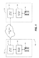
図1は、本発明のルーティングシステムを実施するために、セションルーター及びメディアルーターを用いて説明される通信ネットワーク102を示したブロック図である。図1で示すように、第1のキャリアネットワーク112は、米国マサチューセッツ州WoburnのPingtel株式会社から市販されているSIP電話114、第1のセションルーター116及び第1のメディアルーター118を備えている。第2のキャリアネットワーク132は、インターネット122を介して第1のキャリアネットワーク112に接続されており、第2のSIP電話134、第2のセションルーター138及び第2のメディアルーター136を備えている。ネットワーク112、132間の通信を必要とする第1及び第2のキャリアネットワーク112及び132の範囲内で、SIP又はnon−SIPのいかなる装置も含まれることができる点に留意する必要がある。他のデータソースは、統合化アクセス手段(IAD)、VoIPゲートウェイ(シスコAS5300、Sonus GSX)及びマルチメディアソース(PCs、IP−PBXs)を含むが、これに限定されるものではない。更に、ネットワーク112、132間の通信は、ワイドエリアネットワーク(WAN)又はローカルエリアネットワーク(LAN)によって、その代わりに提供されることができる。又、インターネット122内で、メディア・ルーター118、136が2つのドメイン又はキャリア・ネットワークの間で利用されるので、インターネット122は、その代わりに公共或いはプライベートなデータネットワークドメインであっても良い。
【0018】
或いは、例えば、これに限定されるものではないが境界ルーターのようなルーターは、第1及び第2のメディアルーター118、136間に位置しており、第1及び第2のキャリア・ネットワーク112間の通信を援助する。第1のSIP電話114から第2のSIP電話134への通信は、更に、以下に詳細に説明されているように、第1及び第2のメディアルーター118、136によって提供されるても良い。しかし、例えば境界ルーターの様な追加するルーターが、第1及び第2のキャリアネットワーク112、132間の通信を提供する際に必要でないことは、強調されなければならない。通信は、セションルーター116、138から、直接インターネット122に、又、メディアルーター118、136を介さなくても良いことは、強調されなければならない。
【0019】
現在未定のアプリケーションによる詳細にて説明したように、サポートがタイトルをつけた、シリアルを有するMeLampyらによって、2001年4月27日に出願された09/844,204号の「複数のネットワークを介してRTPフローを制御するシステム及び方法」に記載されているように、第1及び第2のセションルーター116、138は、SIP及びTRIP(telephony routing over IP)を提供することが記載されており、本明細書に引用され開示されているものとする。
【0020】
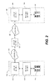
追加するメディアルーターは、第1のメディアルーター118及び第2のメディアルーター136の間で提供される。図2は、本発明の別の実施例に従って、2台の代わりに3台のメディアルーターの使用した実施例を示すブロック図である。このように、第1のキャリアネットワーク112の中で位置する第1のメディアルーター118は、インターネット122を介して、第3のメディアルーター137と通信する。次に、第2のキャリアネットワーク132の範囲内で、第3のメディアルーター137は、インターネット122を介して、第2のメディアルーター136と通信する。第1のメディアルーターからの通信は、第2のメディアルーター、セションルーター、SIPデバイス及び/又はLAN、WAN、或いは他に位置するnon−SIPデバイスへ、繰り返し行われる。
【0021】
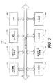
リアルタイムマルチメディアフローがメディアルーター侵入する場合、周知のインタフェースを介したマルチメディアパケットになる。図3は、メディアルーターを更に示しているブロック図である。図3に示す様にメディアルーター118は、フロー品質管理エンジン172、トラフィック管理部174、通信インタフェース176、ホスト処理部178、ネットワーク処理部182、入力装置184及び出力装置186と、内容アドレス指定可能なメモリ(CAM:content addressable memory)189、全外部検索エンジンを備えており、ローカルリンク188を介したメディアルーター118の範囲内で通信する。以上に述べたそれぞれは、CAM189を除いて、現在出願中の’304の特許出願で詳述されている。
【0022】
具体的には、好ましくはトラフィック管理部174は、トラフィック測定値を提供するために、IPセションマルチメディアフロー率又はトラフィックを計測し実施するために使われる。市販のトラフィック管理部174の例としては、米国カリフォルニア州サンディエゴのMMC Networksで売られるNPX5700トラフィック管理装置が挙げられる。本質的に、トラフィック管理部174は、通信インタフェース176を介して流れるマルチメディアパケットの数を計測する。トラフィック管理部174は、ネットワーク処理部182を伴って機能し、メディアルーター118によって転送決定がされると、トラフィック管理部174は、それぞれのIPフローに関連づけられた優先順位で、受信したパケットを待ち行列に入れる。
【0023】
トラフィック管理部174は、受信したマルチメディアパケットを一時的に格納するのためのメモリ(図示せず)を備える。入力される予定から、トラフィック管理部174はRTPマルチメディアフローを観察し、マルチメディアフローに割り当てられた帯域幅外であれば、マルチメディアパケットを落とすか、落とすのに適切なものをマーキングすることにより、最大データレートを強化することができる。トラフィック管理部174は又、割当られた帯域幅及びビット率に従って特定の量を受け入れる様にセションルーター(後に116)によって指示される。従って、マルチメディアがセションルーター116によって許されるより高いビット率で受信すると、より高いビット率で受信したマルチメディアは送信されない。セションルーター116によって特定される特徴は、セションルーター116を使用することなく、メディアルーター118に直接プログラムされることができる点に留意する必要がある。
【0024】
フロー品質管理エンジン172は、観察している個々のユニークなマルチメディアフローフロー品質を計測し、保存する。フロー品質管理エンジン172も、マルチメディアパケットの送信の上流及び下流の失敗をを検出して、修正する。
【0025】
CAM189の使用を経て、ネットワーク処理部182は、中継サービスを提供し、発信元アドレス、目的地アドレス、発信元ポート、目的地ポート又はこれらの項目のいかなる組合せを中継することができる。ネットワーク処理部182は、又、マルチメディアパケットのIPヘッダーにおいて、MPLS(multi−protocol label switching)タグを除去及び/又は挿入することができる。ヘッダー除去については、更に後述する。更にネットワーク処理部142は、マルチメディアパケットに関連づけられた命令を処理する優先順位の項目を変更することにより、マルチメディアパケットのIPヘッダー部に位置したディフサーブコードポイント(diffserv codepoint)を挿入或いは変更することができる。
【0026】
フロー品質管理エンジン172によって提供される品質測定値サービスは、1つのフローに基づいて提供され、マルチメディアフローは、発信元IPアドレス、目的地IPアドレス、発信元ポート、目的地ポート、発信元の仮想LAN(VLAN:virtual local access network)及び/又は目的地の仮想LAN(VLAN)によって定義される。好ましくは品質測定は、ネットワーク処理部182の範囲内でフローの現在の統計を維持しており、適切なフローの集合、最小/最大統計値とを備えている。集められることができる統計の例は、所定の時間窓の待ち時間、ジター及びパケット損失を含む。時間窓はセションルーター116又はメディアルーター118を経て特定されることができる点に留意する必要がある。集積された統計は、送信したマルチメディアパケット、落としたマルチメディアパケット及び複製したマルチメディアパケットそ含む。他に境界線の統計値として参照される最小の統計値及び最大の統計値として、待ち時間、ジター及び時間窓あたりのパケット損失を含んで収集される。
【0027】
ホスト処理部178は、トラフィック管理部174と同様に、上流及びで下流の失敗を検出及び修正することができる。マルチメディアパケットの送信の上流で下流の失敗を検出して、修正するためにホスト処理部178によって使用される方法は、リンク失敗及び外部の管理イベントの利用を含むが、これに限定されるものではない。
【0028】
CAM189は、ネットワーク処理部182によって早く接続できるように、「open/bin」リクエストに従って、変換値を保存し及び/又はバインドするのに利用される。open/binリクエストは’304の特許出願で詳細に議論される。CAM189は、どの出力デバイス186がイーサネット(登録商標)タイプのデバイスかを下調べするIPマッピングのために、メディアアクセス制御アドレスを保存するのに利用される。CAMの一例は、米国カリフォルニア州マウンテンビューのNetlogic Microsystems会社から製造され市販されている。
【0029】
メディアルーター118は、RTPマルチメディアフローのフロー品質統計値を生成することができる。更に、メディアルーター118は、通信ネットワーク102を介して流れるRTPパケットからフロー品質統計値を生成することが可能である。場合によっては、図1で示すように、統計値はメディアルーター間のリンクに関連するだけである。
【0030】
好ましくは、1つ以上の統計は、メディアルーター118介して各々のフローに備えて保存される。これらの統計値は、待ち時間、ジター、パケットあたりのオクテット数及び/又は落としたパケットの数を含むことができるが、これに限定されるものではい。その他の統計が又、メディアルーター118を介した各々のマルチメディアフローに関連づけて格納されることができる点に留意する必要がある。例えば、各々のマルチメディアフローのための統計値を生成するために、メディアルーター118が専用の、これに限られたものではないがRTCP(real−time control protocol)などのプロトコルのバージョンを、接続されたメディアルーター間で走らせて、待ち時間を決定する。ジター及びドロップされたパケット統計値は、メディアルーター118によって自主的に発生されることができる。以下は、待ち時間、ジター及びドロップされたマルチメディアパケットがRTCP情報がない場合、どのように決定されることができるかについて記述する。
【0031】
データフローの待ち時間を測るために、メディアルーター118はマルチメディアフロー上の他の終端点と通信する。おそらく、他の終端点は他のメディアルーターである。但し、終端点がある必要はない。好ましくは、この通信の対象は、終端点がRTPデータフロー待ち時間を決定しようとしているメディアルーター118へ、ループして戻るテストパケットである。環状にされたパケットを受信しているメディアルーター118は、パケットが受け取られたときと、パケットが送信されたときをと比較する。そして、それによって往復の時間を決定する。往復の時間はそれから一方向の時間に近づくために半分にする。そして、それは待ち時間である。
【0032】
パケットループを実行する専用の道を使用するよりはむしろ、RTCPパケットフォーマットが2つのメディアルーターの間で使われることができる。このフォーマットは、(送信報告から)送り主のタイムスタンプの摘出を可能にし、タイムスタンプをループした(受信報告の)パケットに入れることができ、パケットをループにするのにどれくらいかかったか、評価することができる。
【0033】
ジターは、フロー上のパケット間のギャップの変量の測定である。他の定義は、ジターがマルチメディア・フローの待ち時間の変化である。RTPデータフローがメディアルーター118を通過するとき、メディアルーター118はRTPデータフローのジターを測定することができる。マルチメディアパケットがそれは又、メディアルーター118内に位置するネットワーク処理部158に到達すると、タイマーはスタートし、そのRTPデータフローの次のマルチメディアパケットが到着するまで稼働する。マルチメディアパケット間のギャップは、集計に加えられ、「平均の」ジター値を維持する。「平均の」ジター値を、フロー記録における最小/最大値と比較して、新しいジター値が決められるか決定する。ネットワーク処理部182の中に位置するネットワーク処理部メモリ(図示せず)の中に、フロー記録が位置することができる点に留意する必要がある。メディアルーター118の中に位置するメモリは、内部に保存された単一のメモリの中で、又はメディアルーター118の外に位置することを又、強調されなければならない。このプロセスがとても強いプロセッサであっても良い状況において、ジターサンプルは集められることができ、最小/最大値の算出は集められた情報を利用して周期的な基礎に基づいて実行されることができる。
【0034】
ドロップされたパケットは、順番にネット損失パケットを計算することによって決定される。マルチメディアパケットフローが開始すると、受信したマルチメディアパケットに割り当てられるシーケンス番号は観察される。観察されたシーケンス番号は格納されて、次の予想されるシーケンス番号を提供するために+1増加し、それは又、格納される。損失パケット参照して格納されるその情報がネットワーク処理部メモリの中で又は他のいかなるメモリの中でも格納されることができる点に留意する必要がある。
【0035】
マルチメディアパケットは、順番に流れることが一般に期待される。次より大きいシーケンス番号がシーケンス番号が受信されると期待する場合、予想されるシーケンス番号は受信されたシーケンス番号から減じられる、そして、結果は「損失パケット」カウンタの中で格納される。シーケンス番号が下の方にあって、シーケンス番号値を予想するたびに、「損失パケット」カウンタは−1減少させられ、次に予想されるシーケンス番号は変更されない。時間とともに、この過程は、損失パケットの数を正確に計測する。以下のテーブルは、到着しているパケットシーケンス番号の例と、その結果実行された損失パケットの算出を提供している。
【0036】
【表1】
【0037】
或いは、ドロップされたパケットの正確なカウントは、パケットがいつ行方不明か、そして、パケットがジターウインドウの中で現れるかどうか追跡するために用いるブーリアンの2つのスコアボード配列を使用して得られることができる。処理パケットの代わりの方法が、使われることができる。ジター窓が変動しているネットワーク状況を補償するために、音声ゲートウェイにおいて一般的に実行される点に留意する必要がある。ジター窓は、解凍のためのそれらを転送する前に、特定の時間量の間に入って来るパケットを保持するパケットバッファである。この処理はパケットフローを円滑にする効果を有する。そして、に対する圧縮解凍(CODEC)のはね返りを増やし、パケット損失、パケット遅延及び他の送信効果を発生させる。好ましくは、ジター窓はセションルーター116によって定義される。但し、それはメディアルーター118を経て直接定められても良い。
【0038】
スコアボード配列の各々の項目は、特定のシーケンス番号を有するパケットがメディアルーターによって受信したかどうかを表している。スコアボード配列は、ネットワーク処理部メモリの中で又はあらゆるローカルであるか遠いメモリの中でも位置することができる。ブーリアンの各々の配列は、どの軌跡を辿ったどれくらい多くの項目が『失敗』とマークされているかを示すカウンタを備えている。好ましくは、全ての項目は最初に『受信』とマークされている。
【0039】
シーケンス番号がネットワーク処理部182において追われるので、失敗パケット、具体的には、1つ以上インクリメントされたシーケンス番号をもつパケットが、現在の配列の適切な項目が『失敗』とマークされ、失敗カウンタがインクリメントされる。好ましくは、2つの配列は、ジター窓のパケットの最大数を考慮して大きさが設定される。これらの2つの配列は、以下に現在の配列及び古い配列と称する。現在の配列がジター窓の最大値に到達すると、古い配列は再初期化されて、現在の配列になる、そして、現在の配列は古い配列になる。古い配列が消される前に、ドロップされたパケットのカウンタは検索され、データフローに蓄積される。
【0040】
その代わりに限度を越たた古いパケットは受信されると、シーケンス番号は現在のシーケンス番号より少ない場合、ネットワーク処理部は、パケット遅延に従って現行の或いは古い配列のどちらかにおいてシーケンス番号の登録を検索する。ネットワーク処理部182が、失敗とマークされた登録を発見し、項目を変更する場合、ネットワーク処理部182は、失敗パケットの保持している軌跡を利用した配列の失敗パケットのカウンタをデクリメントする。パケットが失敗とマークされない場合、ネットワーク処理部182はパケットが写しであることを示す。シーケンス番号がパケットがジター窓の深さよりはるかにさかのぼるほど古い場合、ネットワーク処理部182は検査を実行しない。計数しているドロップされたパケットの数の計測を実行するこの方法は、RTCPを利用して得るより正確な点に留意する必要がある。
【0041】
本発明によれば、ネットワーク処理部182は又、通信インタフェース176を介して指定された目的地に、マルチメディアパケットの高速送信を提供するために利用される。以下は、高速マルチメディア送信がネットワーク処理部182によって可能にされることを記載する。
【0042】
高速マルチメディア送信
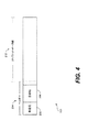
メディアルーター118によって受信されるマルチメディアパケットは、ヘッダー及びIPパケットデータ部を備える。図4は、マルチメディアパケット202の上述した一部を例示している図である。マルチメディアパケット202のヘッダー部分204は、少なくとも発信元部206及び目的地部208を備えており、発信元部206は、どこからパケットが到着したかを示す発信元アドレスを示し、目的地部208は、パケット202にアドレスされた目的地アドレスを示している。
【0043】
ネットワーク処理部182は、メディアルーター118によって受信した後、受信したマルチメディアパケット202に一連の動作を実行する。通常、例えば、リンクプロトコルヘッダーなどのレイヤー2のヘッダーは、受信したマルチメディアパケットから削除される。リンクプロトコルヘッダーの例としては、イーサネット(登録商標)ヘッダー又はHDLCヘッダーを含むが、これに限定されるものではなくても良い。レイヤー2のヘッダーが削除されると、メディアルーター118は、データパケットのレイヤー3のヘッダーを検査する。レイヤー3のヘッダーは、セションルーター116によって割り当てられるか或いはメディアルーター118に直接割り当てられた発信元IP及び目的地IPアドレス、及び発信元IP及び目的地ポートを備えている。このレイヤー3のヘッダーは、標準のIP処理を実行することにより、マルチメディアパケットが適切に形成され、有効であることを確実にする。通常の当業者は、どんな処理がIP処理に含まれるかについて知っているので、この処理の更に議論は本願明細書において提供されない。
【0044】
メディアルーター118がマルチメディアパケットの受信が可能な場合、ヘッダー部204に保存された受信したマルチメディアパケットの特性は、送信される目的地アドレス及びポートに変換される。変換処理は、’304特許において詳述されており、本願明細書において参照する。一方、メディアルーター118がマルチメディアパケットの受信が可能でない場合、パケットはドロップされる。
【0045】
それから、ネットワーク処理部182は、受信したマルチメディアパケットの送信のために使われるメディアルーター118のどの通信インタフェース176であるかを決定する。ネットワーク処理部182は、パケットヘッダーによって特徴づけられる特性を調査することによって通信インタフェース176を決定する。好ましくは、ネットワーク処理部メモリは、メディアルーター118のどの通信インタフェース176が、受信したマルチメディアパケットのマルチメディアパケットの目的地の送信に利用されたかを特定するテーブル又はマップリストを備える。
【0046】
目的地アドレス及びポートにマルチメディアパケットを送信する前に、マルチメディアパケットのレイヤー2のヘッダーは、決定される。以下、レイヤー2のヘッダーを決定するために利用される処理について説明する。
【0047】
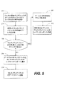
レイヤー2のヘッダーを決定する従来技術方法
図5は、フローチャートであるそのは、レイヤー2のヘッダーを決定するために利用される従来技術方法を示すフローチャートである。このことについては、各々のブロックは、それは指定された論理的機能を実行するための1つ以上の実行可能な指示を備えた、モジュール、セグメント又はコードの部分を表す。他のいくらかの実施で、ブロックにみられる機能はそれ以外の命令が記載されても良いことは、又、強調されなければならない。例えば、連続して指される2ブロックは実質的に並行して事実実行されても良い、又は、関係する機能性によって、更に下の方に明らかにされるので、ブロックは時々逆の命令において実行されても良い。
【0048】
ブロック202で示すように、ローカル通信インタフェース176のIPアドレスのネットワークプリフィックス部の大きさが決定される。ネットワークプリフィックスの大きさがメディアルーター118を利用しているネットワークに従って異なっても良い点に留意する必要がある。例えば、ネットワークプリフィックスは、24の意味のあるビット、16の意味のあるビット又は他のいかなる大きさにも指定されても良く、ネットワークプリフィックスは、ローカル通信インタフェース176IPアドレスの大きさと同じか小さい。好ましくは、ネットワークプリフィックスの大きさは、ネットワーク処理部メモリの中で定められる。
【0049】
一旦ネットワークプリフィックスの計画された大きさが決定されると、受信されたマルチメディアパケットの目的地IPアドレスは、目的地接頭辞がローカル通信インタフェース176のIPアドレスのネットワークプリフィックスの大きさに等しくなるように分割される(ブロック204)。例えばマスキングを利用して、目的地IPアドレスを分割しても良い。以下は、処理をマスキングする例を記載する。ネットワークプリフィックスの大きさが24のビット(1.1.1)に指定され、そして、マルチメディアパケットの目的地IPアドレスが1.1.1.1である場合、目的地IPアドレスはネットワークプリフィックスの各々のビットで、数学的にアンド(論理積)される(1.1.1.1をF.F.F.0でアンドする)。処理をマスキングした結果は、1.1.1.1の目的地プリフィックスである。
【0050】
そして、この目的地プリフィックス及びネットワークプリフィックスは、マルチメディアパケットの目的地が位置するローカルサブネットを決定するために利用される。本願明細書において、「サブネット」の文言は、は、1つの地理的場所にある全てのコンピュータを表す。従来技術において通常の技術のそれらに知られているように、サブネットに分割される組織ネットワークのネットワークを有することによって、ネットワークが単一の共有ネットワークアドレスを有するインターネットに接続することができる。
【0051】
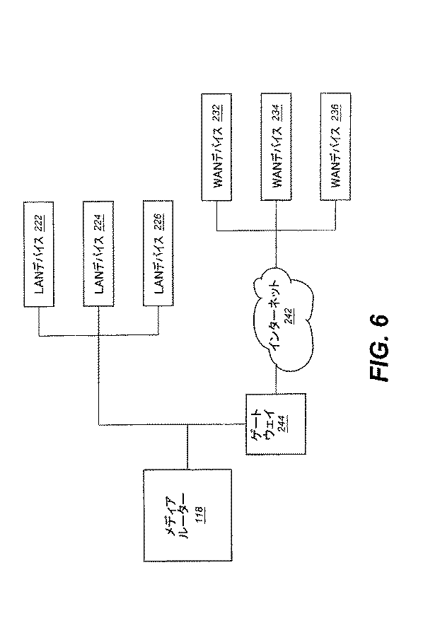
図6は、メディアルーター118と、ローカルサブネットに位置しうるな目的地デバイスの間の通信を示したブロック図である。このLAN及びWANは、ローカルサブネット内に位置するデバイスの一例として図6によって示されているが、他のデバイスが利用されても良い…に留意する必要がある。図6によって示されているように、3台のLAN目的地デバイスは222、224、226で表されており、3台のWAN目的地デバイスは232、234、236で表されている。そこにおいて、WAN目的地デバイス232、234、236はインターネット242を介してメディアルーター118に接続されている。加えて、ゲートウェイ244は一般的にインターネット242に接続されており、LANのために使用されるプロトコルからWANのために使用されるプロトコルに、データリンク層での転換を実行される。セションルーター116及び/又は第2のメディアルーター136がLAN目的地デバイス222、224、226及び/又はWAN目的地デバイス232、234、236であっても良い点に留意する必要がある。
【0052】
公知技術であるように、LAN目的地デバイス222、224、226はネットワークプリフィックスと同じ目的地プリフィックスを有しなければならない。従って、図5に戻ると、分割された後(ブロック204)LAN目的地デバイス222、224、226の目的地プリフィックス値は、ネットワークプリフィックスのビット値と比較され、マルチメディアパケットは、どのLAN目的デバイス222、224、226に行くかを決定する(ブロック206)。LAN目的地デバイス222、224、226の目的地プリフィックスビット値がネットワークプリフィックスに等しい場合、マルチメディアパケットの目的地はそのLANの範囲内である。関連づけられたローカル目的地MAC(media access control)アドレスの検索するために、ネットワーク処理部メモリ内部のマルチメディアパケットのレイヤー2目的地アドレスの検索が実行される(ブロック208)。好ましくは、ネットワーク処理部メモリの中で位置するレイヤー2バインディングテーブルは、目的地IPアドレス及び関連づけられたローカル目的地目的地MACアドレスを保存している。一旦ローカル目的地MACアドレスが分かると、ローカル目的地MACアドレスは、レイヤー2ヘッダー内で、マルチメディアパケットに加えられる(ブロック212)。
【0053】
或いは、LAN目的地デバイス222、224、226の目的地プリフィックス・ビット値がネットワーク・プリフィックスに等しくない場合、マルチメディアパケットはゲートウェイ244に送信される。従って、LAN目的地デバイス222、224、226の目的地プリフィックスビット値がネットワークプリフィックスに等しくない場合、ゲートウェイ244のMACアドレスはレイヤー2ヘッダーとして、マルチメディアパケットに加えられる(ブロック214)。本発明のルーティングシステムによって利用されるゲートウェイ244は1つ以上であり、WANテーブルは、ネットワーク処理部メモリにおいて提供され、目的とする宛先のゲートウェイを決定する点に留意する必要がある。目的とする宛先のゲートウェイが決定されるために、このWANテーブルは目的地IPアドレス及び関連づけられたゲートウェイアドレスを格納している。
【0054】
LAN目的地デバイス222、224、226の目的地プリフィックスビット値がネットワーク・プリフィックスと同じで、レイヤー2バインディングテーブルは目的地IPアドレスを備えていない場合、ネットワーク処理部182は全てのLAN目的地デバイス222、224、226に、アドレス解決リクエストを送信する。LAN目的地デバイス222、224、226がIP目的地であるかどうか決定することができるように、このアドレス解決リクエストはLAN目的地デバイス222、224、226に、マルチメディアパケットのIPアドレスを提供する。LAN目的地デバイス222、224、226がIP目的地である場合、LAN目的地デバイス222、224、226は、ネットワーク処理部182に目的地MACアドレスを返す。しかし、アドレス解決リクエストの答えが指定された時間内でLAN目的地デバイス222、224、226から受信されない場合、マルチメディアパケットはドロップされる。
【0055】
残念なことに、レイヤー2ヘッダーを決定するための上記の処理は、多くの時間を消費するため、本発明のルーティングシステムにおいて高速マルチメディア送信は不可能である。従って、高速マルチメディア送信を実現するために、目的地MACアドレスを備えたレイヤー2ヘッダーを決定及び供給する、速くて効率的な方法提供する以下の方法が利用される。
【0056】
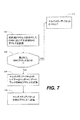
レイヤー2ヘッダーを決定する本発明の方法
図7は、本発明の最良の実施の形態に係るマルチメディアパケットのレイヤー2ヘッダーを決定する方法を示したフローチャートである。ブロック252によって示されてる様に、CAM189を検索して、マルチメディアパケットのレイヤー3目的地IPアドレスをキーとして利用することにより目的地MACアドレスを決定する。問い合わせが行われると、CAM189から戻るMACアドレスが0と同じであるか決定される。本発明によれば、CAM189は常にMACアドレス問い合わせに対応して値を返すことができることを、本願明細書において示されなければならない。
【0057】
ブロック256で示すように、返されたMACアドレスの値がゼロである場合、関連するマルチメディアパケットはドロップされる。しかし、返されたMACアドレスがゼロでない場合、返されたMACアドレスはマルチメディアパケットのレイヤー2ヘッダーに加えられる(ブロック258)。マルチメディアパケットは、それから指定されたMACアドレスに送信される(ブロック260)。以下で、更に目的地MACアドレスの判定を記載する。
【0058】
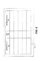
上記したように、レイヤー2ヘッダーを決定するために、本発明のルーティングシステムは、CAM189を利用して、目的地アドレス及び関連するMACアドレスを保存する。図3で示すように、CAM189はネットワーク処理部182の外で、かつメディアルーター118の内部に位置する。図8は、CAM189を更に例示しているブロック図である。図8によって示されるように、CAM189は、目的地IPアドレス列304、重み列306及び目的地MACアドレス列308を備えたレイヤー2バインディングテーブル302を備えており、それぞれは以下に詳細に記載する。当業者に知られているように、CAMは1つのクロックサイクルの中の検索を実行することができる。従って、CAM189の利用する結果、ネットワーク処理部メモリのような会話メモリを使用することより非常に速い検索を行うことができる。レイヤー2バインディングテーブル302の目的地IPアドレス列304は、目的地IPアドレスを備えた一連のセルを備えており、それぞれのセルは、重み値及び関連したMACアドレスが関連づけられている。
【0059】
この重み列306は、重み要素を目的地IPアドレスに加えるために利用される。複数の目的地IPアドレスが同様である状況において、この重み要素は利用され、その結果、好ましい目的地IPアドレスが示される。以下はレイヤー2バインディングテーブル内検索された目的地IPアドレスが1.1.1である例であり、目的地IPアドレス列304の内の2つの異なる目的地IPアドレスは1.1.1及び1.1.1.2である。レイヤー2バインディングテーブル302において目的地IPアドレスの検索が行われると、目的地IPアドレス列304に位置する1.1.1及び1.1.1.2の両方の目的地IPアドレスは好ましい検索結果である。より高い重み値が目的地IPアドレス列304内で、第1の目的地IPアドレス(1.1.1)として提供される場合、第1の目的地IPアドレスが選択され、レイヤー2ヘッダーとして利用され、関連するMACアドレスが返される。より高い重み値が優先的であるために、又は、より低い重み値が優先的になるように、重み値の重要性が確立されても良い点に留意する必要がある。
【0060】
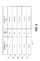
本発明の好ましい実施例に従って、ユニバーサル選択ビット(Xに指定される)は、目的地IPアドレス及び関連するMACアドレスが選ばれても良いことを確実にするために目的地IPアドレス列304の異なるセルの中で割り当てられる。以下は、ユニバーサル選択ビットを利用した一連の例を提供する。図9は、レイヤー2バインディングテーブル302のブロック図であって、ユニバーサル選択ビットを利用する以下の例において利用される。以下の例で利用される値は実証目的で提供されている点に留意する必要がある。従って、他の値は、補充されても良い。
【0061】
図9によって示されているように、目的地IPアドレス列304内のセルは次の通りである。第1のセル322に、1.1.1.1の目的地IPアドレスがある;第2のセル324に、1.1.1.2の目的地IPアドレスがある;第3のセル326に、1.1.1.3の目的地IPアドレスがある;第4のセル328に、1.1.1.Xの目的地IPアドレスがある;そして、第5のセル332に、X.X.X.Xの目的地IPアドレスがある。本願明細書において、ユニバーサル選択ビットを備えない目的地IPアドレスは、LAN目的地デバイス222、224、226を表している。
【0062】
第4のセル328の値がネットワークプリフィックスと同じものであるので、ネットワークプリフィックスと同じで、LAN目的地デバイス222、224、226の目的地IPアドレスより異なる目的地IPアドレスを保証することにより、選択されることができる。更に、第5のセル332及び関連する重み及びMACアドレス値が常に選ばれるように、第5のセル332の値はユニバーサル選択ビットで完全に備えられる。
【0063】
第1のセル322に関連する重み値306は、127である;第2のセル324に関連する重み値は、127である;第3のセルに関連する重み値は、127である;第4のセル328に関連する重み値は、64である;そして、第5のセル332に関連する重み値は、32である。第4のセル328に関連する重み値は、第4のセル328はネットワークプリフィックスと同じなので、第1のセル322、第2のセル324及び第3のセル326より低いことを記載しておく。従って、第1、第2、第3及び第4の目的地IPアドレスが調査された目的地IPアドレスと同じ場合であっても、第1、第2、第3の目的地IPアドレスのうちの1つは選ばれ、関連するMACアドレスはレイヤー2ヘッダーとして利用される。加えて、第5のセル332の目的地IPアドレスが選ばれることは最も少なそうであるために、第5のセル332に関連する重み値は他の全てのセル322、324、326、328と関連する重み値より低く設定される。
【0064】
以下、それぞれのセルに関連づけられたMACアドレス308は、以下に記載するように提供される。第1のセル322に関連するこのMACアドレスは、0:0:0:0:0:1である;第2のセル324に関連するMACアドレスは、0:0:0:0:0:2である;第3のセル326に関連するMACアドレスは、0:0:0:0:0:3である;第4のセル328に関連するMACアドレスは、0:0:0:0:0:0である;そして、第5のセル332に関連するMACアドレスは、1:2:3:4:5:6である。第4のセル328に関連するMACアドレスは、0:0:0:0:0:0は無効なMACアドレスであるので、0:0:0:0:0:0にセットされる点に留意する必要がある。従って、レイヤー2バインディングテーブルで検索された目的地IPアドレスは、第4のセル328と同じビット値を備えており、第1、第2或いは第3のセル322、324、326とは異なる場合、目的地IPアドレスはレイヤー2バインディングを備えていないLAN目的地デバイス222、224、226を参照することが知られている。
【0065】
目的地IPアドレスがLAN目的地デバイス222、224、226に関連し、LAN目的地デバイス222、224、226のMACアドレスが公知でないと決定されると、アドレス検索リクエストは、全てのLAN目的地デバイス222、224、226に送信されても良い。LAN目的地デバイス222、224、226がアドレス検索リクエストに応えた場合、応答しているLAN目的地デバイス222、224、226のMACアドレスは、将来参照できるように、レイヤー2バインディングテーブル302に登録される。IP目的地アドレス及びMACアドレスとの新規な関係の登録は、CAM189がリフレッシュする間に登録されても良い。実際、本発明の別の実施例に従って、アドレス解決リクエストは、レイヤー2バインディングテーブル302の値を更新するためにメディアルーター118の通信インタフェース176から、LAN目的地デバイス222、224、226まで、周期的に送信される。目的地IPアドレスがLAN目的地デバイス222、224、226に関連し、そして、LAN目的地デバイス222、224、226のMACアドレスが公知でないと決定される場合、マルチメディアパケットがその代わりにドロップされても良いことは、又、示されなければならない。
【0066】
加えて、第5のセル332に関連するMACアドレスは、ゲートウェイアドレスにセットされる。従って、目的地IPアドレスが最初の4つのセル322、324、326、328の中で検索されない場合、目的地IPアドレスは第5のセル323の中で、それによってネットワーク処理部158へのゲートウェイのMACアドレスを返す。
【0067】
図9のレイヤー2バインディングテーブル302を用いて、目的地IPアドレス1.1.1.2がCAM189内で検索される場合、第2のセル324、第4のセル328及び第5のセル332はリクエストにマッチする。しかし、各セルに関連する重み要素が参照されると、第2のセル324の目的地IPアドレスが最も適切目的地IPアドレスであることは明瞭である。従って、目的地IPアドレス1.1.1.2に関連したMACアドレス(即ち、0:0:0:0:0:2)は、ネットワーク処理部158に返され、マルチメディアパケットのレイヤー2ヘッダーとして利用する。
【0068】
目的地IPアドレス1.1.1.20がCAM190で検索される場合、第4のセル328及び第5のセル332がリクエストにマッチする。しかし、各々のセルに関連する重み要素が参照されると、第4のセル328の目的地IPアドレスが最も適切な目的地IPアドレスであることは明瞭である。目的地IPアドレスがLAN目的地デバイス222、224、226に関連し、LAN目的地デバイス222、224、226のMACアドレスが公知でないと決定するされるとその結果、アドレス検索リクエストは全てのLAN目的地デバイス222、224、226に送られる。LAN目的地デバイス222、224、226がアドレス検索リクエストに応えた場合、応答しているLAN目的地デバイス222、224、226のMACアドレスが将来参照できるように、レイヤー2バインディングテーブル302に登録される。
【0069】
或いは、目的地IPアドレス2.2.2.2がCAM189内で検索される場合、第5のセル332の目的地IPアドレスはリクエストにマッチする。従って、第5のセル332に関連するMACアドレスが利用され、それによってゲートウェイにマルチメディアパケットの目的地として指定する。
【0070】
従って、CAM189内のユニバーサルに選択されたビット及び重み要素値によって、ルーティングシステムは、早くて効果的な方法で、マルチメディアパケットの目的地がLAN目的地デバイスであるのかWANデバイスであるのかを決定することができる。
【0071】
本発明の上記の実施例、特にあらゆる「好ましい」実施例は、単なる位置実施例にすぎず、本発明の原則を明確に理解するためのものである点は、強調されなければならない。多くの変更及び修正は、実質的に趣旨及び原理から逸脱することのない範囲で、本発明の上記の実施の形態でなされても良い。全てのこの種の修正変更は、この開示及び本発明の範囲内で本願明細書において含まれて、請求項によって保護されている。
【図面の簡単な説明】
【図1】図1は、現在のルーティングシステムを実施する通信ネットワークを示したブロック図である。
【図2】図2は、図1において通信ネットワークによって2台のメディアルーターが利用されているのに対して、3台のメディアルーターが利用された本発明の別の実施例を示したブロック図である。
【図3】図3は、図1のメディアルーターを更に示したブロック図である。
【図4】図4は、図3に示したメディアルーターによって受信することができるマルチメディアパケットの一部を示している図である。
【図5】図5は、フローチャートであるそのは、マルチメディアのパケット(例えば図4で例示されるパケット)のレイヤー2のヘッダーを決定するために利用される従来技術方法を示したフローチャートである。
【図6】図6は、ブロック線図であるそのは、メディアルーターとローカル・サブネットの範囲内に位置する目的地デバイスとの間の通信を示したブロック図である。
【図7】図7は、本発明の好ましい実施例に従って、図5のレイヤー2のヘッダーを決定する方法を示したフローチャートである。
【図8】図8は、図3のCAMを更に示しているブロック図である。
【図9】図9は、ユニバーサル選択ビットを使用する例を提供するために利用されるレイヤー2の結合テーブルのブロック図である。[0001]
TECHNICAL FIELD OF THE INVENTION
The present invention relates to systems and methods for improving telecommunications, and in particular, communications between switched networks and packet networks.
[0002]
[Prior art]
The Public Switched Telephone Network (PSTN) is effective real-time, ie, a user can pick up any one of nearly one billion phones and dial any one of nearly one billion endpoints. Expanded to a multimedia communication session tool that can be used. Through some developments, it has enabled automated networks such as numbering plans, electronic switching and routing, and also enabled networked signal generation systems.
[0003]
The Internet is based on the Internet Protocol (IP), just as PSTN is a layer-based method. Multimedia packets are routed and forwarded from one link to the next (ie, from the source of the data flow to the destination of the data flow). Each multimedia packet has an IP address and has 32 bits, eg, in Internet Protocol version 4 (IPv4). Each IP address also has a certain number of bits for the network part and a certain number of bits for the host part.
[0004]
IP routers are used to send multimedia packets from one network (or link) and place the packets on another network (or link). The tables provided in the IP router contain information or criteria to determine the best way to route multimedia packets. Examples of this information may be indications of network link status and programmed distance. Using intelligent devices on both sides of the network domain, assign a temporary address to route multimedia packets through the network as the packet leaves the network, based on the original address on the other side of the network. It is possible to return to. This is the basis of many current virtual private network (VPN) products and is understood in the prior art.
[0005]
Knowing the status of adjacent communication links and available routes by network elements ensures that network elements (eg, telephone network switches, data network routers) can perform their associated tasks. Can help you. Signaling systems are used to provide this information. In the telephone network, any signaling system 7 (SS7) or a system equivalent to SS7 is used as a system for sending a signal to the system. The SS7 network is separate from the voice network and is used to switch data messages related to the business connecting telephone calls and the maintenance of the signaling network. In addition, the SS7 digital signal standard is used as an interface to the PSTN IP world. As is known to those skilled in the art, SS7 utilizes messages whose structure traverses from one network entity to another and is independent of the actual voice and data to which they pertain. To traverse the message, this message structure, called a packet, utilizes an envelope.
[0006]
During transmission of a multimedia packet to a destination, network elements may exchange source and / or destination addresses of the multimedia packet. Unfortunately, in multimedia packets, the process of determining and changing the source and destination addresses is time consuming, thereby preventing high speed multimedia packet transmission.
[0007]
[Means for Solving the Problems]
In view of the foregoing, the preferred embodiment of the present invention generally relates to a system for determining a destination for an Internet Protocol packet.
[0008]
Typically, with respect to the structure of the routing system, the system searches memory (189) for memory and a destination Internet Protocol address (304) associated with the Internet Protocol packet (202), and a destination Internet Protocol address (304). Read the destination MAC address (308) identified by, and if the value of the destination MAC address (308) is zero, drop the Internet Protocol packet (202) and make the destination MAC address (308) equal to zero. If not, use a processor that performs the step of adding the MAC address (308) to the Internet Protocol packet (202) as the destination of the packet. Further, the memory is preferably a content addressable memory.
[0009]
The present invention may be viewed as providing a method for determining a destination of an Internet Protocol packet. In this regard, the method can be broadly summarized by the following steps. The memory (189) is searched for a destination Internet Protocol address (304) associated with the Internet Protocol packet (202), and a destination MAC address (308) identified by the destination Internet Protocol address (304) is read. If the value of the destination MAC address (308) is zero, drop the Internet Protocol packet (202); if the destination MAC address (308) is not equal to zero, drop the Internet Protocol packet (202) as the destination of the packet. To the Internet Protocol packet (202).
[0010]
Other systems and methods of the present invention will be apparent to those skilled in the art from a consideration of the following drawings and detailed description. All such additional systems, methods, features and advantages are intended to be included within the scope of this description, and within the scope of the present invention, protected by the appended claims.
[0011]
BEST MODE FOR CARRYING OUT THE INVENTION
The present invention can be better understood with reference to the following drawings. The components of the drawings are not necessarily proportional. Emphasis has been placed upon clearly illustrating the principles of the present invention. Further, in the drawings, reference numerals are assigned to corresponding parts in some of the drawings.
[0012]
The routing system of the present invention can be implemented in software, firmware, hardware or a combination. In a preferred embodiment of the present invention, which is not limited to this example, some systems are implemented in software executed by a network processing unit.
[0013]
Software based on this routing system is provided with a list of instructions to be executed in order to realize a logical function. The software based on this source determination system obtains an instruction from an instruction execution system, an apparatus, or a device such as a processing unit of a computer-based system included in the system, or an instruction execution system, an apparatus, or a device, and obtains the instruction. The present invention is embodied in any computer-readable storage medium that utilizes or is connected to another system that executes the program. In this specification, a “computer-readable storage medium” is a means used to include, store, communicate, propagate, and transmit a program, or connect to an instruction execution system, apparatus, or device.
[0014]
The computer readable storage medium is, but not limited to, an electronic, magnetic, optical, electromagnetic, infrared, or semiconductor system, apparatus, device, or propagation medium. Examples of computer readable storage media include electronic connections (electronic) with one or more wires, portable computer disks (magnet), random access memory (RAM) (magnet), read-only memory (ROM) (Magnetic), erasable programmable read-only memory (EPROM or flash memory) (magnetic), optical fiber (optical) and portable compact disk read-only memory (CD-ROM) (optical) Not a typical list. Also, the computer-readable storage medium may be paper or another suitable medium on which the program is printed, for example, engineeringly scanning, compiling, translating, or other suitable paper or other medium. Processing may be performed in any suitable manner, electronically obtained, and read into a computer memory as needed.
[0015]
In transmitting multimedia data packets from a first endpoint to a second endpoint, it is desirable to process many transmission routes and select an optimal transmission route. The session router selects a number of routes and processes in order to select from a combination of similar session initiation protocol (SIP) agents using various distribution strategies. With this processing, the path of the resulting real-time transport protocol (RTP) flow can be managed. The media router directs the resulting RTP flow that is selected and processed by the session router that has passed certain thresholds. The combination of session routers and media routers can provide high quality boundaries between various IP networks. Without a session router and a media router, data packets would escape all the way through the underlying network. Here, the multimedia includes at least one of text, image, video, animation, sound, data, and discrete media, or at least one of them.
[0016]
The processing and selection of the route is described in the “Multimedia Flow” of 09 / 911,256, filed July 23, 2001 by the pending US patent application MeLampy et al. (Hereinafter the '256 patent application). Systems and Methods for Controlling RTP Flow over Many Networks with Routing ", which is incorporated herein by reference. No. 09 / 911,304, filed Jul. 23, 2001 by MeLampy et al. (Hereinafter “the '304 patent application”), entitled “Systems and Methods for Providing Quick Rerouting of Real-Time Multimedia Flows”. The U.S. patent application, which is incorporated herein by reference, teaches the use of a media router that directs the resulting RTP flow as selected and processed by a session router having a particular threshold. The combination of the routers and methods disclosed in the '256 and' 304 and patent applications disclosed herein create high quality boundaries between various IP networks. Without these mechanisms, data packets flow on any of the ways permitted by the network.
[0017]
FIG. 1 is a block diagram illustrating a
[0018]
Alternatively, a router, such as, but not limited to, a border router, is located between the first and
[0019]
As described in the details by the currently pending application, support has been entitled, Serialized by MeLampy et al., Ser. No. 09 / 844,204, filed Apr. 27, 2001, entitled "Multiple Networks." The first and
[0020]
Additional media routers are provided between the
[0021]
When a real-time multimedia flow enters a media router, it becomes a multimedia packet over a well-known interface. FIG. 3 is a block diagram further illustrating a media router. As shown in FIG. 3, the
[0022]
Specifically, preferably, the
[0023]
The
[0024]
The flow
[0025]
Through the use of the
[0026]
The quality measurement service provided by the flow
[0027]
The
[0028]
The
[0029]
[0030]
Preferably, one or more statistics are stored for each flow via
[0031]
To measure the latency of the data flow, the
[0032]
Rather than using a dedicated path to perform a packet loop, the RTCP packet format can be used between the two media routers. This format allows the extraction of the sender's timestamp (from the transmission report), puts the timestamp in the looped (reception report) packet, and evaluates how long it took to loop the packet. Can be.
[0033]
Jitter is a measure of the variation of the gap between packets on a flow. Another definition is jitter changes in the latency of a multimedia flow. As the RTP data flow passes through the
[0034]
Dropped packets are determined by calculating net lost packets in turn. When the multimedia packet flow starts, the sequence number assigned to the received multimedia packet is observed. The observed sequence number is stored and incremented by +1 to provide the next expected sequence number, which is also stored. It should be noted that the information stored with reference to the lost packet can be stored in the network processor memory or in any other memory.
[0035]
Multimedia packets are generally expected to flow in order. If a sequence number greater than the next expects a sequence number to be received, the expected sequence number is subtracted from the received sequence number, and the result is stored in a "lost packet" counter. Each time the sequence number is lower and the sequence number value is expected, the "lost packet" counter is decremented by -1 and the next expected sequence number is not changed. Over time, this process accurately measures the number of lost packets. The following table provides an example of an arriving packet sequence number and the calculation of the resulting lost packet.
[0036]
[Table 1]
[0037]
Alternatively, an accurate count of dropped packets is obtained using two scoreboard arrays of booleans used to track when packets are missing and whether packets appear in the jitter window. Can be. Alternative methods of processing packets can be used. It should be noted that jitter windows are commonly implemented in voice gateways to compensate for changing network conditions. Jitter windows are packet buffers that hold incoming packets for a certain amount of time before transferring them for decompression. This process has the effect of smoothing the packet flow. It also increases the compression / decompression (CODEC) rebound, causing packet loss, packet delay and other transmission effects. Preferably, the jitter window is defined by
[0038]
Each entry in the scoreboard array indicates whether a packet with a particular sequence number has been received by the media router. The scoreboard array can be located in the network processor memory or in any local or remote memory. Each array of booleans has a counter that indicates how many items along which trajectory have been marked "failed." Preferably, all items are initially marked as "received".
[0039]
Since the sequence number is tracked in the
[0040]
Instead, when an outdated old packet is received, if the sequence number is less than the current sequence number, the network processing unit searches for the registration of the sequence number in either the current or old sequence according to the packet delay. I do. When the
[0041]
According to the present invention, the
[0042]
High-speed multimedia transmission
The multimedia packet received by the
[0043]
After being received by the
[0044]
If the
[0045]
Then, the
[0046]
Before sending the multimedia packet to the destination address and port, the
[0047]
Prior art method for determining
FIG. 5 is a flowchart, which shows a prior art method used to determine the
[0048]
As indicated by
[0049]
Once the planned size of the network prefix is determined, the destination IP address of the received multimedia packet is such that the destination prefix is equal to the size of the network prefix of the
[0050]
The destination prefix and the network prefix are used to determine a local subnet where the destination of the multimedia packet is located. As used herein, the term "subnet" refers to all computers at one geographic location. By having a network of organizational networks divided into subnets, as is known to those of ordinary skill in the prior art, the network can connect to the Internet with a single shared network address.
[0051]
FIG. 6 is a block diagram illustrating communication between a
[0052]
As is known in the art, LAN destination devices 222, 224, 226 must have the same destination prefix as the network prefix. Thus, returning to FIG. 5, after segmentation (block 204), the destination prefix value of the LAN destination device 222, 224, 226 is compared to the bit value of the network prefix, and the multimedia packet is transmitted to any LAN destination device. It is determined whether to go to 222, 224, 226 (block 206). If the destination prefix bit value of the LAN destination device 222, 224, 226 is equal to the network prefix, the destination of the multimedia packet is within the range of the LAN. A search for a
[0053]
Alternatively, if the destination prefix bit value of the LAN destination device 222, 224, 226 is not equal to the network prefix, the multimedia packet is sent to the gateway 244. Thus, if the destination prefix bit value of the LAN destination device 222, 224, 226 is not equal to the network prefix, the gateway 244 MAC address is added to the multimedia packet as a
[0054]
If the destination prefix bit values of the LAN destination devices 222, 224, and 226 are the same as the network prefix, and the
[0055]
Unfortunately, the above process for determining the
[0056]
Method of the invention for determining a
FIG. 7 is a flowchart illustrating a method for determining a
[0057]
If the value of the returned MAC address is zero, as indicated by
[0058]
As described above, in order to determine the
[0059]
The
[0060]
According to a preferred embodiment of the present invention, the universal select bits (designated as X) are different in the destination
[0061]
As shown by FIG. 9, the cells in the destination
[0062]
Since the value of the
[0063]
The
[0064]
Hereinafter, the
[0065]
If the destination IP address is associated with the LAN destination device 222, 224, 226 and the MAC address of the LAN destination device 222, 224, 226 is determined to be unknown, the address search request will be sent to all LAN destination devices. 222, 224, and 226. When the LAN destination devices 222, 224, and 226 respond to the address search request, the MAC addresses of the responding LAN destination devices 222, 224, and 226 are registered in the
[0066]
In addition, the MAC address associated with the
[0067]
When the destination IP address 1.1.1.2 is searched in the
[0068]
When the destination IP address 1.1.1.20 is searched in the CAM 190, the
[0069]
Alternatively, if the destination IP address 2.2.2.2 is looked up in the
[0070]
Thus, with the universally selected bits and weight factor values in the
[0071]
It should be emphasized that the above-described embodiments of the invention, and in particular, any "preferred" embodiment, are merely exemplary embodiments and are for a clear understanding of the principles of the invention. Many changes and modifications may be made in the above embodiments of the invention without departing substantially from the spirit and principles. All such modifications are included herein within the scope of this disclosure and the present invention and protected by the following claims.
[Brief description of the drawings]
FIG. 1 is a block diagram illustrating a communication network implementing a current routing system.
FIG. 2 is a block diagram illustrating another embodiment of the present invention in which three media routers are utilized while two media routers are utilized by the communication network in FIG. It is.
FIG. 3 is a block diagram further illustrating the media router of FIG. 1;
FIG. 4 is a diagram showing a part of a multimedia packet that can be received by the media router shown in FIG. 3;
FIG. 5 is a flowchart, which illustrates a prior art method used to determine a
FIG. 6 is a block diagram, which shows communication between a media router and destination devices located within a local subnet.
FIG. 7 is a flowchart illustrating a method of determining a
FIG. 8 is a block diagram further illustrating the CAM of FIG. 3;
FIG. 9 is a block diagram of a
Claims (10)
前記目的地インターネットプロトコルアドレス(304)によって識別される目的地MACアドレス(308)を読み込むステップと、
前記目的地MACアドレス(308)の値がゼロである場合、前記インターネットプロトコルパケット(202)をドロップするステップと、
前記MACアドレス(308)が0でない場合(252)、前記パケット(202)の前記目的地として前記インターネットプロトコルパケット(202)に、前記目的地MACアドレス(308)を追加するステップ
を備えることを特徴とするインターネットプロトコルパケット(202)の目的地を決定する方法Searching the memory for a destination Internet Protocol address (304) associated with the Internet Protocol packet (202);
Reading a destination MAC address (308) identified by the destination Internet Protocol address (304);
Dropping the internet protocol packet (202) if the value of the destination MAC address (308) is zero;
Adding the destination MAC address (308) to the Internet Protocol packet (202) as the destination of the packet (202) if the MAC address (308) is not 0 (252). To determine the destination of the Internet Protocol packet (202) to be used
前記MACアドレス(308)を、前記インターネットプロトコルパケット(202)のレイヤー2ヘッダーに追加するステップ
を備えていることを特徴とする請求項1に記載の方法。The step of adding the destination MAC address (308) to the Internet protocol packet (202) comprises:
The method of claim 1, comprising adding the MAC address (308) to a Layer 2 header of the Internet Protocol packet (202).
目的地インターネットプロトコルアドレス(304)と、
前記メモリ(189)の中で、各々の目的地インターネットプロトコルアドレス(304)と関連した重み要素(306)と、
目的地MACアドレス(308)を備えており、
前記重み要素(306)は、前記メモリ(189)の一連の行から1つの行を選択するのに使われ、前記行のそれぞれは、1つの目的地インターネットプロトコルアドレス(304)、1つの重み値(306)及び1つも目的地MACアドレス(308)を備えており、選択された前記行は、前記目的地インターネットプロトコルアドレス(304)によって識別される前記目的地MACアドレス(308)を読み込むステップを実行するのに利用される
ことを特徴とする請求項1に記載の方法。The memory (189)
A destination Internet Protocol address (304);
A weighting element (306) associated with each destination Internet Protocol address (304) in said memory (189);
It has a destination MAC address (308),
The weighting element (306) is used to select a row from the series of rows of the memory (189), each of the rows having one destination Internet protocol address (304), one weighting value. (306) and one or more destination MAC addresses (308), wherein the selected row reads the destination MAC address (308) identified by the destination Internet Protocol address (304). The method of claim 1, wherein the method is used to perform.
ことを特徴とする請求項3に記載の方法。At least one of the rows comprises a destination Internet Protocol address (304) with at least one universal bit, where the universal bit is a bit that excludes any value, and the universal bit is Ensuring that said step of searching said memory (189) for said destination Internet protocol address (304) associated with said Internet protocol packet (202), in said memory (189) 4. The method according to claim 3, wherein (304) is always provided.
ことを特徴とする請求項3に記載の方法。The method of claim 3, wherein when an invalid destination MAC address (308) is provided in a row, the destination of the Internet Protocol packet (202) indicates a LAN destination device. The described method.
前記LAN目的地デバイスが前記インターネットプロトコルパケット(202)の目的地であった場合、無効な前記MACアドレス(308)を前記LAN目的地デバイスのアドレスに置換するステップ
を備えることを特徴とする請求項5に記載の方法。Sending an address search request to the LAN destination device to determine if the LAN destination device is the destination of the Internet Protocol packet (202);
If the LAN destination device is the destination of the Internet Protocol packet (202), replacing the invalid MAC address (308) with the address of the LAN destination device. 5. The method according to 5.
インターネットプロトコルパケット(202)に関連づけられた目的地インターネットプロトコルアドレス(304)を求めて前記メモリ(189)を検索し、
前記目的地インターネットプロトコルアドレス(304)によって識別される目的地MACアドレス(308)を読み込み、
前記目的地MACアドレス(308)の値がゼロである場合、前記インターネットプロトコルパケット(202)をドロップし、
前記目的地MACアドレス(308)がゼロでない場合、前記パケットの前記目的地として前記MACアドレス(308)を前記インターネットプロトコルパケット(202)に追加する
処理部(182)
を備えることを特徴とするインターネットプロトコルパケット(202)の目的地を決定するシステム。A memory (189);
Searching the memory (189) for a destination Internet Protocol address (304) associated with the Internet Protocol packet (202);
Reading the destination MAC address (308) identified by the destination Internet Protocol address (304);
If the value of the destination MAC address (308) is zero, drop the Internet Protocol packet (202);
A processing unit (182) for adding the MAC address (308) to the Internet protocol packet (202) as the destination of the packet when the destination MAC address (308) is not zero;
A system for determining a destination of an Internet Protocol packet (202), comprising:
目的地インターネットプロトコルアドレス(304)と、
前記メモリ(189)の中で、各々のインターネットプロトコルアドレス(304)も関連した重み要素(306)と、
目的地MACアドレス(308)を備えており、
前記重み要素(306)は、前記メモリ(189)の一連の行から1つの行を選択するのに使われ、前記行のそれぞれは、1つの目的地インターネットプロトコルアドレス(304)、1つの重み値(306)及び1つの目的地MACアドレス(208)を備えており、選択された前記行は、前記目的地インターネットプロトコルアドレス(304)によって識別される前記目的地MACアドレス(308)を読み込むステップを実行するのに利用される
ことを特徴とする請求項7に記載の方法。The memory (189)
A destination Internet Protocol address (304);
In said memory (189), each Internet Protocol address (304) also has an associated weighting element (306);
It has a destination MAC address (308),
The weighting element (306) is used to select a row from the series of rows of the memory (189), each of the rows having one destination Internet protocol address (304), one weighting value. (306) and one destination MAC address (208), wherein the selected row reads the destination MAC address (308) identified by the destination Internet Protocol address (304). The method of claim 7, wherein the method is used to perform.
ことを特徴とする請求項9に記載の方法。10. The method of claim 9, wherein providing an invalid destination MAC address (308) in a row indicates that the destination of the Internet Protocol packet (202) is a LAN destination device. The described method.
Applications Claiming Priority (1)
| Application Number | Priority Date | Filing Date | Title |
|---|---|---|---|
| US10/103,408 US7260085B2 (en) | 2002-03-21 | 2002-03-21 | System and method for determining a destination for an internet protocol packet |
Publications (2)
| Publication Number | Publication Date |
|---|---|
| JP2004040766A true JP2004040766A (en) | 2004-02-05 |
| JP4102690B2 JP4102690B2 (en) | 2008-06-18 |
Family
ID=27788372
Family Applications (1)
| Application Number | Title | Priority Date | Filing Date |
|---|---|---|---|
| JP2003079686A Expired - Lifetime JP4102690B2 (en) | 2002-03-21 | 2003-03-24 | System and method for determining the destination of an internet protocol packet |
Country Status (5)
| Country | Link |
|---|---|
| US (1) | US7260085B2 (en) |
| EP (1) | EP1347621B1 (en) |
| JP (1) | JP4102690B2 (en) |
| AT (1) | ATE312466T1 (en) |
| DE (1) | DE60302597T2 (en) |
Families Citing this family (36)
| Publication number | Priority date | Publication date | Assignee | Title |
|---|---|---|---|---|
| US7844729B1 (en) | 1999-05-03 | 2010-11-30 | Digital Envoy, Inc. | Geo-intelligent traffic manager |
| US20060224752A1 (en) * | 1999-05-03 | 2006-10-05 | Parekh Sanjay M | Determining geographic locations of private network Internet users |
| US7685311B2 (en) | 1999-05-03 | 2010-03-23 | Digital Envoy, Inc. | Geo-intelligent traffic reporter |
| US6757740B1 (en) | 1999-05-03 | 2004-06-29 | Digital Envoy, Inc. | Systems and methods for determining collecting and using geographic locations of internet users |
| US20060146820A1 (en) * | 2002-11-26 | 2006-07-06 | Robert Friedman | Geo-intelligent traffic manager |
| JP3819368B2 (en) * | 2003-02-24 | 2006-09-06 | 株式会社東芝 | Communication control device, communication control method, server device with communication control, communication control method and communication control program using server device with communication control |
| US9160714B2 (en) * | 2003-06-30 | 2015-10-13 | Telefonaktiebolaget L M Ericsson (Publ) | Using tunneling to enhance remote LAN connectivity |
| US7594259B1 (en) * | 2004-09-15 | 2009-09-22 | Nortel Networks Limited | Method and system for enabling firewall traversal |
| US8194640B2 (en) * | 2004-12-31 | 2012-06-05 | Genband Us Llc | Voice over IP (VoIP) network infrastructure components and method |
| US20070291734A1 (en) * | 2005-05-27 | 2007-12-20 | Medhavi Bhatia | Methods and Apparatus for Multistage Routing of Packets Using Call Templates |
| CN1881908A (en) * | 2005-06-13 | 2006-12-20 | 华为技术有限公司 | Method for measuring MPLS network performance parameter |
| US7502320B2 (en) * | 2005-07-06 | 2009-03-10 | Cisco Technology, Inc. | Method and apparatus for network-based admission control using path-coupled quality of service signaling |
| JP4559927B2 (en) * | 2005-07-14 | 2010-10-13 | パナソニック株式会社 | Communication data processing apparatus and method |
| KR100793345B1 (en) * | 2005-12-01 | 2008-01-11 | 삼성전자주식회사 | Packet processing method and apparatus therefor in voice / data integration system |
| JP4692258B2 (en) * | 2005-12-07 | 2011-06-01 | 株式会社日立製作所 | Router device and communication system |
| US9060047B2 (en) | 2005-12-21 | 2015-06-16 | Genband Us Llc | Media stream management |
| US7860990B2 (en) * | 2006-01-31 | 2010-12-28 | Genband Us Llc | Session data records and related alarming within a session over internet protocol (SOIP) network |
| US7865612B2 (en) * | 2006-01-31 | 2011-01-04 | Genband Us Llc | Method and apparatus for partitioning resources within a session-over-internet-protocol (SoIP) session controller |
| US7861003B2 (en) | 2006-01-31 | 2010-12-28 | Genband Us Llc | Adaptive feedback for session over internet protocol |
| US8204043B2 (en) * | 2006-02-28 | 2012-06-19 | Genband Us Llc | Quality of service prioritization of internet protocol packets using session-aware components |
| US8259706B2 (en) * | 2006-02-28 | 2012-09-04 | Genband Us Llc | Multistage prioritization of packets within a session over internet protocol (SOIP) network |
| US8509218B2 (en) * | 2006-02-28 | 2013-08-13 | Genband Us Llc | Prioritization within a session over internet protocol (SOIP) network |
| US8095683B2 (en) * | 2006-03-01 | 2012-01-10 | Cisco Technology, Inc. | Method and system for mirroring dropped packets |
| US8195736B2 (en) * | 2006-08-08 | 2012-06-05 | Opnet Technologies, Inc. | Mapping virtual internet protocol addresses |
| KR101223950B1 (en) * | 2006-09-26 | 2013-01-18 | 리베우 리미티드 | Remote transmission system |
| US9154395B2 (en) * | 2006-10-05 | 2015-10-06 | Cisco Technology, Inc. | Method and system for optimizing a jitter buffer |
| US7916731B2 (en) * | 2006-11-30 | 2011-03-29 | Broadcom Corporation | Method and system for efficient rapid loss detection in a bonding system |
| US7912062B2 (en) | 2007-09-28 | 2011-03-22 | Genband Us Llc | Methods and apparatus for managing addresses related to virtual partitions of a session exchange device |
| JP5205075B2 (en) * | 2008-02-13 | 2013-06-05 | パナソニック株式会社 | Encryption processing method, encryption processing device, decryption processing method, and decryption processing device |
| JP5109940B2 (en) * | 2008-11-20 | 2012-12-26 | 富士通株式会社 | Input edge router identification method, program, and computer |
| US8443107B2 (en) * | 2009-11-11 | 2013-05-14 | Digital Envoy, Inc. | Method, computer program product and electronic device for hyper-local geo-targeting |
| US10931624B2 (en) * | 2015-01-20 | 2021-02-23 | Tata Communications (America) Inc. | Service dependent IP addresses |
| US9979557B2 (en) * | 2015-08-10 | 2018-05-22 | Hughes Network Systems, Llc | Carrier grade Ethernet layer 2 over layer 3 satellite backbones (L2oL3SB) |
| CN109995659B (en) * | 2017-12-29 | 2022-03-01 | 阿里巴巴集团控股有限公司 | Network communication method and device |
| US11178107B2 (en) * | 2019-09-30 | 2021-11-16 | Michael Schloss | System and method for detecting surreptitious packet rerouting |
| EP4197185B1 (en) * | 2020-08-17 | 2026-05-06 | ARRIS Enterprises LLC | Processing real-time-streaming-protocol (rtsp) packets to enhance video-on-demand services |
Family Cites Families (11)
| Publication number | Priority date | Publication date | Assignee | Title |
|---|---|---|---|---|
| WO1997013345A1 (en) * | 1995-10-04 | 1997-04-10 | Kawasaki Steel Corporation | Network interconnecting device |
| JP3638742B2 (en) | 1996-11-29 | 2005-04-13 | アンリツ株式会社 | Router |
| US6041058A (en) * | 1997-09-11 | 2000-03-21 | 3Com Corporation | Hardware filtering method and apparatus |
| US6256314B1 (en) * | 1998-08-11 | 2001-07-03 | Avaya Technology Corp. | Apparatus and methods for routerless layer 3 forwarding in a network |
| US6912223B1 (en) * | 1998-11-03 | 2005-06-28 | Network Technologies Inc. | Automatic router configuration |
| JP4156112B2 (en) * | 1998-12-25 | 2008-09-24 | 富士通株式会社 | High-speed search method and high-speed search device |
| EP1041775A1 (en) * | 1999-03-30 | 2000-10-04 | International Business Machines Corporation | Router monitoring in a data transmission system utilizing a network dispatcher for a cluster of hosts |
| JP3403971B2 (en) * | 1999-06-02 | 2003-05-06 | 富士通株式会社 | Packet transfer device |
| WO2000079765A1 (en) | 1999-06-23 | 2000-12-28 | At & T Wireless Services, Inc. | Reverse tunneling methods and apparatus for use with private computer networks |
| JP3407717B2 (en) * | 2000-06-20 | 2003-05-19 | 日本電気株式会社 | LAN communication path control system and control method |
| US20040001492A1 (en) * | 2002-07-01 | 2004-01-01 | Johnson Erik J. | Method and system for maintaining a MAC address filtering table |
-
2002
- 2002-03-21 US US10/103,408 patent/US7260085B2/en not_active Expired - Lifetime
-
2003
- 2003-03-20 DE DE60302597T patent/DE60302597T2/en not_active Expired - Lifetime
- 2003-03-20 AT AT03006352T patent/ATE312466T1/en not_active IP Right Cessation
- 2003-03-20 EP EP03006352A patent/EP1347621B1/en not_active Expired - Lifetime
- 2003-03-24 JP JP2003079686A patent/JP4102690B2/en not_active Expired - Lifetime
Also Published As
| Publication number | Publication date |
|---|---|
| US7260085B2 (en) | 2007-08-21 |
| ATE312466T1 (en) | 2005-12-15 |
| DE60302597D1 (en) | 2006-01-12 |
| DE60302597T2 (en) | 2006-06-29 |
| US20030179761A1 (en) | 2003-09-25 |
| JP4102690B2 (en) | 2008-06-18 |
| EP1347621A1 (en) | 2003-09-24 |
| EP1347621B1 (en) | 2005-12-07 |
Similar Documents
| Publication | Publication Date | Title |
|---|---|---|
| JP4102690B2 (en) | System and method for determining the destination of an internet protocol packet | |
| JP4287168B2 (en) | System and method for determining source of IP packet | |
| JP4316898B2 (en) | System and method for collecting statistics in a packet network | |
| TWI803687B (en) | System for routing optimization and method thereof | |
| JP7468969B2 (en) | Apparatus for use in a first network node and an apparatus for use in a controller | |
| US8218536B2 (en) | Routing protocol with packet network attributes for improved route selection | |
| JP4394336B2 (en) | System and method for determining flow quality statistics for real-time transport protocol data flow | |
| US7031311B2 (en) | System and method for providing rapid rerouting of real-time multi-media flows | |
| US7142532B2 (en) | System and method for improving communication between a switched network and a packet network | |
| JP4390498B2 (en) | System and method for providing session admission control | |
| US8018852B2 (en) | Equal-cost source-resolved routing system and method | |
| JP2001298475A (en) | Path setting apparatus and method in label switching network | |
| JP2003179599A (en) | System and method for providing encryption for rerouting of real time multi-media flows | |
| CN101632273A (en) | Methods, systems, and computer program products for source-aware IP routing at a media gateway | |
| US20060018255A1 (en) | Defining a static path through a communications network to provide wiretap law compliance | |
| US8553539B2 (en) | Method and system for packet traffic congestion management | |
| US6950429B2 (en) | IP data transmission network using a route selection based on level 4/5 protocol information | |
| RU2004117074A (en) | ADDRESSING AND ROUTING IN WIRELESS NETWORK NETWORKS | |
| Al Mamun et al. | Performance Evaluation of Routing Protocols for Video Conference over MPLS VPN Network. | |
| US7330429B2 (en) | Method and apparatus for internet protocol transaction routing | |
| CN103503383B (en) | Communication system, router, switch hub and communication means | |
| US8225389B2 (en) | Method and system to provide physical port security in a digital communication system | |
| Dominguez-Dorado et al. | An architecture to provide guarantee of service (GoS) to MPLS | |
| JP3825438B2 (en) | Label switching network and label edge router |
Legal Events
| Date | Code | Title | Description |
|---|---|---|---|
| A621 | Written request for application examination |
Free format text: JAPANESE INTERMEDIATE CODE: A621 Effective date: 20060120 |
|
| A977 | Report on retrieval |
Free format text: JAPANESE INTERMEDIATE CODE: A971007 Effective date: 20080205 |
|
| TRDD | Decision of grant or rejection written | ||
| A01 | Written decision to grant a patent or to grant a registration (utility model) |
Free format text: JAPANESE INTERMEDIATE CODE: A01 Effective date: 20080304 |
|
| A61 | First payment of annual fees (during grant procedure) |
Free format text: JAPANESE INTERMEDIATE CODE: A61 Effective date: 20080324 |
|
| FPAY | Renewal fee payment (event date is renewal date of database) |
Free format text: PAYMENT UNTIL: 20110328 Year of fee payment: 3 |
|
| R150 | Certificate of patent or registration of utility model |
Ref document number: 4102690 Country of ref document: JP Free format text: JAPANESE INTERMEDIATE CODE: R150 Free format text: JAPANESE INTERMEDIATE CODE: R150 |
|
| R250 | Receipt of annual fees |
Free format text: JAPANESE INTERMEDIATE CODE: R250 |
|
| FPAY | Renewal fee payment (event date is renewal date of database) |
Free format text: PAYMENT UNTIL: 20120328 Year of fee payment: 4 |
|
| FPAY | Renewal fee payment (event date is renewal date of database) |
Free format text: PAYMENT UNTIL: 20130328 Year of fee payment: 5 |
|
| R250 | Receipt of annual fees |
Free format text: JAPANESE INTERMEDIATE CODE: R250 |
|
| FPAY | Renewal fee payment (event date is renewal date of database) |
Free format text: PAYMENT UNTIL: 20130328 Year of fee payment: 5 |
|
| FPAY | Renewal fee payment (event date is renewal date of database) |
Free format text: PAYMENT UNTIL: 20140328 Year of fee payment: 6 |
|
| R250 | Receipt of annual fees |
Free format text: JAPANESE INTERMEDIATE CODE: R250 |
|
| R250 | Receipt of annual fees |
Free format text: JAPANESE INTERMEDIATE CODE: R250 |
|
| R250 | Receipt of annual fees |
Free format text: JAPANESE INTERMEDIATE CODE: R250 |
|
| R250 | Receipt of annual fees |
Free format text: JAPANESE INTERMEDIATE CODE: R250 |
|
| R250 | Receipt of annual fees |
Free format text: JAPANESE INTERMEDIATE CODE: R250 |
|
| R250 | Receipt of annual fees |
Free format text: JAPANESE INTERMEDIATE CODE: R250 |
|
| R250 | Receipt of annual fees |
Free format text: JAPANESE INTERMEDIATE CODE: R250 |
|
| R250 | Receipt of annual fees |
Free format text: JAPANESE INTERMEDIATE CODE: R250 |
|
| R250 | Receipt of annual fees |
Free format text: JAPANESE INTERMEDIATE CODE: R250 |
|
| R250 | Receipt of annual fees |
Free format text: JAPANESE INTERMEDIATE CODE: R250 |
|
| EXPY | Cancellation because of completion of term |