JP2004040742A - Door scope image enlargement display unit - Google Patents
Door scope image enlargement display unit Download PDFInfo
- Publication number
- JP2004040742A JP2004040742A JP2002225346A JP2002225346A JP2004040742A JP 2004040742 A JP2004040742 A JP 2004040742A JP 2002225346 A JP2002225346 A JP 2002225346A JP 2002225346 A JP2002225346 A JP 2002225346A JP 2004040742 A JP2004040742 A JP 2004040742A
- Authority
- JP
- Japan
- Prior art keywords
- display unit
- door
- image
- door scope
- scope
- Prior art date
- Legal status (The legal status is an assumption and is not a legal conclusion. Google has not performed a legal analysis and makes no representation as to the accuracy of the status listed.)
- Pending
Links
Images
Landscapes
- Closed-Circuit Television Systems (AREA)
- Studio Devices (AREA)
Abstract
Description
【0001】
【発明の属する技術分野】
この発明は、ドアーを開ける前に、訪問者を確認するドアスコープの可視画像を拡大表示して見易くする、ドアスコープ画像拡大表示ユニットに関するものである。
【0002】
【従来の技術】
従来から、特に玄関ドアーに取り付けられているドアスコープを見るとき、ドアー面に目が接するほど近づかないと訪問者を確認することが出来なかった。
【0003】
【発明が解決しようとする課題】
このため、覗き見るという姿勢の罪悪感、体勢に、無理を生じ、訪問者を確認しないままドアーを開けたり、又、目を近づけるため、ドアスコープが一瞬暗くなり、中に人が居て外を覗いているのが判る場合がある。
本発明は、拡大して見ることで、無理な姿勢をする必要がなく、ドアスコープ室内側にドアスコープ画像拡大表示ユニットを装着することで、中に人が居ることを判らなくすることを提供するものである
【0004】
【課題を解決するための手段】
上記目的を達成する本発明に係るドアスコープ画像拡大表示ユニットは、
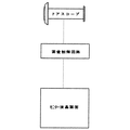
ドアスコープの可視画像を解像し、その画像を電子映像に変換するための両像制御回路を有し、その映像を表示するモニター液晶画面と、電源部、スイッチ部から成る表示ユニットに、磁石を固着したもので、この磁石を内装した表示ユニットを、ドアスコープの室内側に装着することで、ドアスコープ可視画像を拡大して見ることが出来るようにしたものである。
【0005】
【発明の実施形態】
次に本発明を図面に基づいて説明する。
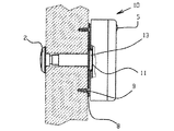
図1は本発明に係る要部断面平面図、図2は図1の正面図、図3は本発明のブロック図、図4は木製、アルミ製ドアーに取り付ける場合の実施例を示す要部断面平面図、図5は図4の要部断面側面図である。
【0006】
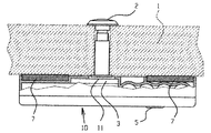
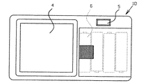
図1、図2に示すように画像制御回路3、モニター液晶画面4、電源部6、スイッチ部5から成る表示ユニット10の裏面に磁石7を固着したものであり、表示ユニット10のドアスコープ2との合わせ位置に穴11を明けたものでる。
この表示ユニット10を従来からあるドアスコープ付きの鉄製ドアー1に使用するには、表示ユニット10の穴11をドアスコープ2のフランジ部に合わせ、装着する。表示ユニット10には磁石7が固着されているのでその磁力で鉄製ドアー1と表示ユニット10は不動となる。
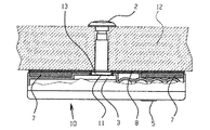
木製、アルミドアーの場合は、図4、図5に示すように、鉄板8のバーリング穴13をドアスコープ2のフランジ部に合わせ、ねじ9で、木製、アルミドアー12に固定する。上記に示す鉄製ドアー1と同様に使用できる。磁力はドアーの開け閉め、地震等の振動に耐える強さとする。又、ドアスコープは既設の魚眼レンズ式でもよく、広角レンズ等に交換又は新設しても良い
【0007】
訪問者を確認する時、スイッチ5を押すことで電源がONとなり,ドアスコープの画像が、モニター液晶画面に拡大表示される。スイッチ5は押している間だけ電源ONでもよく、タイマー機能を持たせ一度押すだけで設定した時間内のみ電源ONでもよい。
【0008】
【発明の効果】
以上のように、本発明に係るドアスコープ画像拡大表示ユニットによれば、画面を見るという行為から、覗き見るという姿勢の罪悪感がなく、ドアーに目を近づける無理な姿勢を取ることなく訪問者を確認できる。又、ドアスコープ室内側に表示ユニットを装着することで、室内の光が遮断され、中に居る人がドアーに近づいたことを判らなくする効果もあり防犯上有効なものである。
又、周知の防犯カメラ、テレビ付きインターホン等は、音声、映像機能の他、カメラ、ビデオ、ビデオ再生機能、接近センサ等多機能を搭載し非常に高価である。これらを既設の住居に新規に取り付ける場合、配線、取り付け工事が必要となりさらに高価なものとなる。本発明のドアスコープ画像拡大表示ユニットによれば、安全に、確実に、簡単に見易くする機能だけにすることで安価に提供できるものである。
【図面の簡単な説明】
【図1】本発明に係る要部断面平面図
【図2】図1の正面図
【図3】本発明のブロック図
【図4】本発明に係る木製、アルミ製ドアーに取り付ける場合の実施例を示す要部断面平面図
【図5】図4の要部断面側面図
【符号の説明】
1 鉄製ドアー 11 穴
2 ドアスコープ 12 木製、アルミ製ドアー
3 画像制御回路 13 バーリング穴
4 モニター液晶画面
5 スイッチ部
6 電源部
7 磁石
8 鉄板
9 ねじ
10 表示ユニット[0001]
TECHNICAL FIELD OF THE INVENTION
The present invention relates to an enlarged doorscope image display unit that enlarges and displays a visible image of a doorscope for confirming a visitor before opening a door.
[0002]
[Prior art]
Conventionally, especially when looking at a door scope attached to an entrance door, it was not possible to identify a visitor unless the eyes were close enough to touch the door surface.
[0003]
[Problems to be solved by the invention]
For this reason, the guilt and posture of the peeping posture may be overwhelmed, and the door may be opened without confirming the visitor, or the door scope may be momentarily darkened so that the eyes can be approached. You may find that you are looking into the.
The present invention provides that it is not necessary to take an unreasonable posture by magnifying and viewing, and by mounting the doorscope image enlarged display unit inside the doorscope room, it is possible to obscure that there is a person inside. [0004]
[Means for Solving the Problems]
A door scope image enlarged display unit according to the present invention that achieves the above object,
It has a dual image control circuit for resolving the visible image of the door scope and converting the image into an electronic image, a monitor liquid crystal screen for displaying the image, a display unit consisting of a power supply unit and a switch unit, a magnet The display unit containing the magnet is mounted on the indoor side of the door scope so that the visible image of the door scope can be enlarged and viewed.
[0005]
DETAILED DESCRIPTION OF THE INVENTION
Next, the present invention will be described with reference to the drawings.
1 is a plan view of a cross section of a main part according to the present invention, FIG. 2 is a front view of FIG. 1, FIG. 3 is a block diagram of the present invention, and FIG. FIG. 5 is a plan view, and FIG.
[0006]
As shown in FIGS. 1 and 2, a
To use the
In the case of a wooden or aluminum door, as shown in FIGS. 4 and 5, the
When confirming the visitor, the power is turned on by pressing the
[0008]
【The invention's effect】
As described above, according to the door scope image enlarged display unit according to the present invention, there is no guilt of an attitude of peeping from the act of looking at the screen, and the visitor does not take an unreasonable posture of approaching the door. Can be confirmed. Also, by mounting the display unit inside the door scope room, the light in the room is blocked, and there is an effect that a person in the room cannot recognize that it has approached the door, which is effective for crime prevention.
Known security cameras, intercoms with televisions, and the like are very expensive because they have various functions such as a camera, a video, a video playback function, and a proximity sensor in addition to audio and video functions. When these are newly installed in an existing house, wiring and installation work are required, which further increases the cost. ADVANTAGE OF THE INVENTION According to the doorscope image enlarged display unit of this invention, it can provide cheaply only by the function which makes it easy to see safely, reliably, and simply.
[Brief description of the drawings]
FIG. 1 is a plan view of a cross section of a main part according to the present invention. FIG. 2 is a front view of FIG. 1. FIG. 3 is a block diagram of the present invention. FIG. FIG. 5 is a cross-sectional side view of a main part of FIG. 5;
DESCRIPTION OF SYMBOLS 1
Claims (1)
Priority Applications (1)
| Application Number | Priority Date | Filing Date | Title |
|---|---|---|---|
| JP2002225346A JP2004040742A (en) | 2002-07-01 | 2002-07-01 | Door scope image enlargement display unit |
Applications Claiming Priority (1)
| Application Number | Priority Date | Filing Date | Title |
|---|---|---|---|
| JP2002225346A JP2004040742A (en) | 2002-07-01 | 2002-07-01 | Door scope image enlargement display unit |
Publications (1)
| Publication Number | Publication Date |
|---|---|
| JP2004040742A true JP2004040742A (en) | 2004-02-05 |
Family
ID=31711499
Family Applications (1)
| Application Number | Title | Priority Date | Filing Date |
|---|---|---|---|
| JP2002225346A Pending JP2004040742A (en) | 2002-07-01 | 2002-07-01 | Door scope image enlargement display unit |
Country Status (1)
| Country | Link |
|---|---|
| JP (1) | JP2004040742A (en) |
Cited By (2)
| Publication number | Priority date | Publication date | Assignee | Title |
|---|---|---|---|---|
| CN104575267A (en) * | 2013-10-23 | 2015-04-29 | 鸿富锦精密工业(深圳)有限公司 | Display module |
| US9520558B2 (en) | 2011-03-17 | 2016-12-13 | Micron Technology, Inc. | Semiconductor structures and memory cells including conductive material and methods of fabrication |
-
2002
- 2002-07-01 JP JP2002225346A patent/JP2004040742A/en active Pending
Cited By (2)
| Publication number | Priority date | Publication date | Assignee | Title |
|---|---|---|---|---|
| US9520558B2 (en) | 2011-03-17 | 2016-12-13 | Micron Technology, Inc. | Semiconductor structures and memory cells including conductive material and methods of fabrication |
| CN104575267A (en) * | 2013-10-23 | 2015-04-29 | 鸿富锦精密工业(深圳)有限公司 | Display module |
Similar Documents
| Publication | Publication Date | Title |
|---|---|---|
| US8797451B2 (en) | Embedded camera with privacy filter | |
| US20040257649A1 (en) | Combination window and video display with dual sided viewability | |
| US20150093102A1 (en) | Monitoring apparatus, monitoring system, and monitoring method | |
| CN102957901B (en) | A kind of display system | |
| JP2004040742A (en) | Door scope image enlargement display unit | |
| CA2313916A1 (en) | Lift installation | |
| US20120200756A1 (en) | Flat screen window and multi-function display | |
| CN103375109B (en) | Display door device with display function | |
| JP7078423B2 (en) | Automatic door installation status presentation method, equipment and system | |
| JP2007201580A (en) | A series of devices for making existence of wall-mounting tv inconspicuous when not viewed | |
| JP2002044650A (en) | Monitoring imaging device and method of mounting monitoring imaging device | |
| CN210428575U (en) | Entrance guard's equipment with remote monitoring function | |
| KR20230131516A (en) | System of watching real time outside view by display panel attached on the glass wall inside indoor living space | |
| US20030086186A1 (en) | Door mirror viewer | |
| WO2001038926A1 (en) | A method of selective viewing | |
| KR20090020333A (en) | Door monitoring system and door opening and closing system having same | |
| CN204795388U (en) | An electronic visual cat's eye for a monitoring system | |
| KR100648668B1 (en) | Plasma display panel | |
| KR20150087066A (en) | The video can be seen outside the front door system | |
| KR20120091793A (en) | The video can be seen outside the front door system | |
| JPS63226491A (en) | Door | |
| CN201695901U (en) | Metal door with electronic door mirror device | |
| KR200482783Y1 (en) | Interactive monitoring apparatus for confront doors | |
| KR20150020040A (en) | Interactive monitoring apparatus and a control method for confront doors | |
| KR20040085336A (en) | Apparatus for controlling projector position of projection television |
Legal Events
| Date | Code | Title | Description |
|---|---|---|---|
| A621 | Written request for application examination |
Free format text: JAPANESE INTERMEDIATE CODE: A621 Effective date: 20050517 |
|
| A131 | Notification of reasons for refusal |
Free format text: JAPANESE INTERMEDIATE CODE: A131 Effective date: 20051108 |
|
| A871 | Explanation of circumstances concerning accelerated examination |
Free format text: JAPANESE INTERMEDIATE CODE: A871 Effective date: 20051013 |
|
| A975 | Report on accelerated examination |
Free format text: JAPANESE INTERMEDIATE CODE: A971005 Effective date: 20051026 |
|
| A521 | Request for written amendment filed |
Free format text: JAPANESE INTERMEDIATE CODE: A523 Effective date: 20051206 |
|
| A02 | Decision of refusal |
Free format text: JAPANESE INTERMEDIATE CODE: A02 Effective date: 20060328 |