JP2004040740A - Manual focus device - Google Patents
Manual focus device Download PDFInfo
- Publication number
- JP2004040740A JP2004040740A JP2002198967A JP2002198967A JP2004040740A JP 2004040740 A JP2004040740 A JP 2004040740A JP 2002198967 A JP2002198967 A JP 2002198967A JP 2002198967 A JP2002198967 A JP 2002198967A JP 2004040740 A JP2004040740 A JP 2004040740A
- Authority
- JP
- Japan
- Prior art keywords
- focus
- image
- shift
- aperture stop
- display
- Prior art date
- Legal status (The legal status is an assumption and is not a legal conclusion. Google has not performed a legal analysis and makes no representation as to the accuracy of the status listed.)
- Granted
Links
Images

Landscapes
- Studio Devices (AREA)
- Focusing (AREA)
- Lens Barrels (AREA)
- Diaphragms For Cameras (AREA)
Abstract
【課題】絞りを光軸と垂直に移動させ、撮像された画像のズレによってピント状態を表示してフォーカス調節が行なえるようにする。
【解決手段】被写体光路上で左右にシフト移動が可能な開口絞りを設ける。開口絞りを右シフトさせたときの画像と左シフトさせたときの画像のズレを検出し、ピントズレの大きさを割り出す。開口絞りが右シフトした時の画像と左シフトした時の画像とからスプリットイメージを作成し、これをモニタ表示する。フォーカスリングの操作量がリングセンサ7aで検出され、ピントズレの大きさとフォーカスリングの操作量とからスプリットイメージの移動量が算出され、フォーカス操作と連動したスプリットイメージの移動表示が行なわれる。
【選択図】 図7A diaphragm is moved perpendicularly to an optical axis, and a focus state is displayed by a deviation of a captured image so that focus adjustment can be performed.
An aperture stop capable of shifting right and left on a subject optical path is provided. A shift between the image when the aperture stop is shifted to the right and the image when the aperture is shifted to the left is detected, and the size of the focus shift is determined. A split image is created from the image when the aperture stop is shifted to the right and the image when the aperture is shifted to the left, and this is displayed on the monitor. The amount of operation of the focus ring is detected by the ring sensor 7a, the amount of movement of the split image is calculated from the magnitude of the focus shift and the amount of operation of the focus ring, and the split image is moved and displayed in conjunction with the focus operation.
[Selection] Figure 7
Description
【0001】
【発明の属する技術分野】
本発明は、スプリットイメージや二重像を観察しながらフォーカス操作が行えるマニュアルフォーカス装置に関するものである。
【0002】
【従来の技術】
二重像合致式や上下像合致式の距離計をファインダに内蔵させた距離計連動カメラが広く知られている。距離計連動カメラでは、フォーカス操作によるピント状態の変化が被写体像のズレの変化として観察され、目視による高精度なピント合わせが可能である。二重像合致式ファインダでは、ファインダ像と距離計像とによる二重像がファインダの視野内で観察される。ピント合わせを行なうには、フォーカス操作に連動して移動する距離計像をファインダ像に合致させる。上下像合致式ファインダは、ファインダ光路内のマイクロスプリットイメージプリズムにより、ファインダ視野内の一部に被写体の上下分割像を形成する。この上下分割像はフォーカス操作に連動してそれぞれが左右対称に移動し、ピントの合った状態では分割像が合致する。
【0003】
また、特開平9−214813号公報、特開2001−309210号公報等に記載されているように、二重像やスプリットイメージを光学的に形成する距離計を組み込む代わりに、撮像された被写体の電子画像をピント調節に利用したファインダが知られている。これらのファインダでは、ピントズレの大きさに応じて食い違って表示された被写体画像をフォーカス操作に連動して移動表示させており、光学部品の数を減らして省スペース化と低コスト化を可能にしている。
【0004】
ピント合わせに連動した画像の移動表示と、合焦時における画像の合致表示とを行なうためには、ピントズレの大きさが予め求められている必要がある。従来では、赤外線を利用して測定された被写体距離からピントズレを算出する三角測距方式や、撮影光軸に対称な光路上で取り込んだ撮影光を2つのラインセンサでそれぞれ受光し、その光電信号の位相差からピントズレを算出する位相差検出方式が一般的である。
【0005】
【発明が解決しようとする課題】
しかしながら、三角測距方式によってピントズレの大きさを算出する場合には、撮像素子に加え、アクティブ測距用の投光素子や位置検出素子など高い組み込み精度を必要とする電気部品が設けられるため、製造コストが上昇するという問題がある。同様にして、従来の位相差検出方式では、撮影光を分光する光学系やラインセンサ等が別途設けられるために、製造コストが上昇するという問題点がある。
【0006】
本発明は、上記問題点が考慮され、撮像素子から得られる画像信号を利用してピント状態を表示することができ、手動による良好なピント合わせが可能なマニュアルフォーカス装置を提供することを目的とする。
【0007】
【課題を解決するための手段】
上記目的を達成するために、本発明のマニュアルフォーカス装置は、被写体光路上に設けられた開口絞りを光軸と垂直に移動させ、絞りの視差によって非合焦時にズレの生じた被写体光を撮像し、双方の画像を表示するものである。撮像面上で生じる被写体光のズレの大きさはピントズレの大きさに応じて変化し、ピントズレのない合焦状態では被写体光にズレは生じない。これを利用し、開口絞りの移動経路上の二地点で撮像された被写体光を同時に表示出力し、ピントズレの程度が両者の画像のズレの程度を見比べることで判断できるようにしている。
【0008】
請求項2記載の発明は、開口絞りの移動時に撮像された被写体画像のズレからピントズレを算出し、このピントズレに基づいてピント状態を表示するものである。被写体画像の表示ズレによってピント状態を正確に知るためには、撮像画素数に匹敵する表示画素数が必要となるが、ピントズレの大きさを求めておくことで、例えば被写体画像のズレを補助的に拡大表示でき、表示画素数を上げずに精度の高いピント合わせが行なえる。
【0009】
請求項3記載の発明は、電子画像によって従来の光学的スプリットイメージと同等な表示を行なうもので、フォーカス操作によってピント合わせが行なわれた際に、表示ズレの与えられた被写体画像を合致表示させている。
【0010】
【発明の実施の形態】
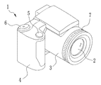
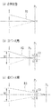
図1において、本発明を内蔵したデジタルスチルカメラ1は、撮像レンズ2を保持した鏡筒3、グリップ部4、レリーズボタン5、撮影モード切替ダイヤル6が設けられている。レリーズボタン5は、半押し操作と全押し操作の二段階の押下操作が可能に構成されている。鏡筒3の外周上にはフォーカスリング7が設けられ、その回転操作によって撮影時のピント合わせが行える。
【0011】
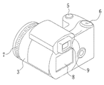
図2において、デジタルスチルカメラ1の背面には、バックモニタ8、ファインダ9が設けられている。バックモニタ8は、被写体画像をフルカラーで表示することが可能な液晶表示パネルで構成されている。また、ファインダ9の内部には、小型のカラー液晶モニタが設けられている。バックモニタ8とファインダ9内の小型モニタとは、その作動が切り替え制御され、ファインダ9の使用時はバックモニタ8が強制オフされる。ファインダ9を使用すれば、バックモニタ8の使用時に比べて消費電力を節約することができる。
【0012】
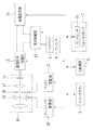
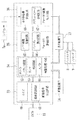
図3において、デジタルスチルカメラ1には、主制御部11、撮像信号処理部12、表示制御部13、画像記憶部14が設けられている。主制御部11は、予めプログラムされた動作シーケンスに従って各部に制御信号を出力し、カメラ全体の電気的な作動を管理する。撮像信号処理部12は、撮像部15から出力された画像信号の増幅処理、画像処理等を行なう。表示制御部4は、バックモニタ8やファインダ9の小型モニタに被写体画像を表示出力する。画像記憶部14は、レリーズボタン5が全押し操作されたとき、撮像信号処理部12から出力された画像信号を画像データとして記憶する。
【0013】
撮像部15は、ズームレンズ16とフォーカスレンズ17、開口絞り18、CCD撮像素子19から構成されている。ズームレンズ16は、ズームモータを備えたズームレンズ駆動部20により光軸方向に駆動され、CCD撮像素子19に結像する被写体像を光学的に変倍させる。フォーカスレンズ17は、フォーカスリング7の操作に伴って光軸方向に移動し、被写体距離に応じた合焦位置でCCD撮像素子19上に被写体光を結像させる。フォーカスリング17には、その回転操作量を検出するリングセンサ7aが設けられている。アイリス駆動部21は、開口絞り18の開口径を調節するとともに、開口絞り18を光軸に直交する面内でシフトさせる。
【0014】
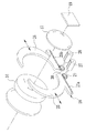
図4において、開口絞り18は、2枚の絞り羽根25,26から構成されている。絞り羽根25,26の下部には、平歯部25a,26aが形成されている。絞り羽根25,26は、アイリスモータ27,28によって駆動される。アイリスモータ27,28の駆動軸上には、平歯部25a,26aに噛合する小歯車29,30が設けられている。このラックピニオンの駆動により、絞り羽根25,26のそれぞれが独立して左右方向へ自在に移動し、開口絞り18の連続した開口径調節と、開口絞り18のシフト移動とが行なわれる。
【0015】
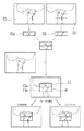
図5において、開口絞り18は光軸対称な2つの測距位置P1とP2の間をシフトする。図5(a)に示すように、フォーカスレンズ17が物点O1からの光を撮像面PI に結像させる位置にあるとき、開口絞り18が位置P1に移動したときを考える。物点O1からの主光線R1は、光軸A1上の点S1で撮像面PI に達する。物点O1より遠くにある物点O2の主光線R2は、結像面PI の手前で光軸A1と交差し、撮像面PI 上の点S2に達する。また、物点O1よりも近くにある物点O3の主光線R3は、光軸A1と交差せずに、撮像面PI 上の点S3に達する。開口絞り18が位置P2に移動したときには、図5(b)に示すように、主光線R1,R2,R3は結像面PI 上の点S1,S2’,S3’にぞれぞれ到達する。
【0016】
図6(a)において、物点O1からの光は撮像面PI 上で結像し、これを合焦状態として示している。図6(b)では、物点O2からの光が撮像面PI の手前で結像する様子を前ピン状態として示している。前ピン状態における画像のズレG2は、点S2と点S2’との距離である。また、図6(c)に後ピン状態として示すように、物点O3からの光は撮像面PI の後方で結像する。前ピン状態にあるときの画像ズレG2を正、後ピン状態にあるときの画像ズレG3を負と定めておけば、フォーカスレンズ17を移動すべき方向がわかる。
【0017】
開口絞り18から撮像面PI までの距離が被写体距離に比べて十分小さければ、開口絞り18の各位置での開口中心と、撮像面PI までの主光線の光路とによって、相似関係に近似できる2つの三角形が形成される。開口絞り18の往復のシフト移動量Mと、画像ズレ量Gとからその相似比が求められるので、撮像面PI から各被写体距離における結像面までの距離、すなわちピントズレの大きさがわかる。ピントズレの大きさがわかれば、フォーカスレンズ17の現在位置から合焦位置までの距離が求められる。
【0018】
図7において、撮像信号処理部12は、画像信号取込回路33と画像処理回路34、フォーカス評価回路35、フォーカス画像出力回路36とから構成されている。画像信号取込回路33には、オートゲインコントローラ40と画素混合回路41が設けられている。オートゲインコントローラ40は、CCD撮像素子19の出力信号の平均レベルが常に一定になるようにゲインを調節しながら増幅処理を行い、画像の輝度を補完する。画素混合回路41は、画像中で隣接する画素の輝度を加算して1画素分の輝度として置換する処理を行い、解像度を下げて画像のコントラストを補正する。オートゲインコントローラ40と画素混合回路41は、設定状態に応じていずれか一方が作動する。
【0019】
画像処理回路34には、ホワイトバランス回路42、ガンマ補正回路43、ADコンバータ44が設けられている。ホワイトバランス回路42は、画像信号に対してRGBの各設定ゲインに基づいた増幅処理を行い、ホワイトバランス調節を行なう。ガンマ補正回路43は、画像信号のコントラストガンマを補正する。各処理が行なわれた画像信号は、ADコンバータ44でデジタル変換される。
【0020】
フォーカス評価回路35には、シフト画像記憶回路45とピントズレ算出回路46が設けられている。シフト画像記憶回路45は、開口絞り18の移動時に撮像された二フレーム分の画像を記憶する。ピントズレ算出回路46は、記憶された二つの被写体画像を解析し、両画像間の位置ズレを画素単位で割り出す。この画像ズレの大きさからピントズレの大きさが算出され、フォーカス画像出力回路36にピントズレ情報が出力される。
【0021】
フォーカス画像出力回路36には、スプリットイメージ合成回路47と表示移動量算出回路48とが設けられている。スプリットイメージ合成回路47は、シフト画像記憶回路45から読み出した二フレームの画像をそれぞれ切り抜き処理して合成し、ピント状態を表示するためのスプリットイメージに変換する。表示移動量算出回路48は、フォーカスリング7の操作に伴うピントズレの変化分をスプリットイメージの表示移動量に変換する。
【0022】
表示制御部13は、画像処理回路34からの出力画像とフォーカス画像出力回路36からの出力されたスプリットイメージとをバックモニタ8やファインダ9内のモニタに表示出力する。図8に示すように、モニタ上では、フォーカス調節エリア50と被写界表示エリア51が画面の中央と周囲とで区切られて表示される。被写界表示エリア51には、開口絞り18の開口中心が光軸上にあるときに撮像された被写体画像が表示される。フォーカス調節エリア50には、開口絞り18の左シフト時に撮られた右寄り画像52と、右シフト時の左寄り画像53の一部がそれぞれ上下に分割された上分割画像52aと下分割画像53aとが表示される。
【0023】
フォーカスリング7が操作されると、リングセンサ7aで検出された回転操作量情報が、主制御部11を介して表示移動量算出回路48に入力される。表示移動量算出回路48は、この回転数情報に基づいてスプリットイメージの表示移動量を算出する。スプリットイメージ合成回路47は、算出された移動表示量に基づいて、シフト画像記憶回路45に記憶された二フレームの画像の切り抜き位置を変更し、これらを合成処理した二次スプリットイメージを表示制御部13に出力する。これにより、フォーカスリング7が操作される度に、フォーカス調節エリア50内の上分割像52aと下分割像53aが左右対称に移動表示される。ピントズレが小さくなるとスプリットイメージの表示ズレが小さくなり、ピントが合った状態で合致する。一方、ピントズレが大きくなるとスプリットイメージの表示ズレが大きくなる。
【0024】
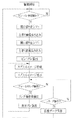
次に、図9を用いて本発明の作用を説明する。CCD撮像素子19が駆動すると被写体光の撮像が開始され、画像信号取込回路33には一定の撮像速度でフレームごとの画像信号が入力される。画像信号取込回路33では、画像信号の増幅処理又は画素混合処理がフレームごとに行われ、画像の輝度が補正される。画像信号は表示制御部13に出力され、撮像された各フレームの被写体画像がモニタ上に連続表示される。
【0025】
撮像が開始された後、レリーズボタン5を半押し操作、又はフォーカスリング7を微操作することで、ピントズレの測定が開始される。主制御部11からアイリス駆動部21にはシフト駆動開始信号が送られ、アイリス駆動部21は、小歯車29,30の回転方向が同じになるようにアイリスモータ27,28を駆動させる。絞り羽根25,26は同方向に移動し、開口絞り18がシフトする。
【0026】
開口絞り18のシフトが開始されると、表示制御部13はモニタ上の被写体画像をフリーズ表示させる。アイリス駆動部21は、最初に開口絞り18を右方向へシフトさせる。開口絞り18が一定距離移動すると右シフトが停止する。このときにCCD撮像素子19から出力された画像信号がフォーカス評価回路35に入力され、左寄り画像53がシフト画像記憶回路45に記憶される。
【0027】
次に、アイリス駆動部21は開口絞り18を左方向へシフトさせる。開口絞り18は右シフト時の停止位置と光軸対称な位置まで移動する。右シフトが終了すると、CCD撮像素子19から出力された画像信号がフォーカス評価回路35に入力され、右寄り画像52がシフト画像記憶回路45に記憶される。
【0028】
開口絞り18は光軸上の位置に戻り、モニタ上ではフリーズ表示が終了して被写体の表示が再開される。フォーカス評価回路35では、シフト画像記憶回路45に記憶された二フレーム分の画像データがピントズレ算出回路46に読み出される。ピントズレ算出回路46は、画像ズレの大きさを割り出し、この画像ズレからピントズレの大きさを算出する。算出されたピントズレの大きさは、ピントズレ情報としてフォーカス画像出力回路36送られる。
【0029】
スプリットイメージ合成回路47では、フォーカス調節エリア50内に表示される一次スプリットイメージが作成される。一次スプリットイメージは表示制御部13に出力され、モニタ上にはフォーカス調節エリア50が出現する。フォーカスリング7が操作されると、その回転操作量情報が表示移動量算出回路48に入力される。表示移動量算出回路48では、回転操作量情報に基づいて表示ズレの大きさが算出され、表示ズレの大きさが変更された二次スプリットイメージが作成される。二次スプリットイメージは表示制御部13に出力され、フォーカス調節エリア50の各分割画像が左右対称に移動した画像が表示される。
【0030】
フォーカスリング7が操作される度にスプリットイメージの移動表示処理が行なわれ、フォーカスレンズ17が合焦位置に近づくと、スプリットイメージの表示ズレは小さくなり、フォーカスレンズ17が合焦位置に達するとスプリットイメージが合致する。レリーズボタン5が全押し操作されると、主制御部11にレリーズ操作信号が送られる。画像処理回路34から出力された画像信号は画像記憶部14に送られ、レリーズ操作時に撮像された画像が保存される。画像の保存が終了すると、フォーカス調節エリア50が消えてモニタ上には被写体画像が表示される。
【0031】
なお、上記実施形態では、開口絞りを光軸対称な二地点間で移動させてフォーカスエリアを画面中心に設定しているが、開口絞りの左右のシフト移動量を偏らせることでフォーカスエリアを画面中心から左右方向に変更することもできる。また、開口絞りを左右上下に二次元移動可能に構成することで、フォーカスエリアを撮影範囲の任意の領域に設定することもできる。
【0032】
また、上記実施形態では、開口絞りの移動時に撮影された被写体画像を利用してスプリットイメージを作成しているが、例えば、基準となる静止画像と透明度が設定された移動画像との重ね合わせ表示によって、二重像合致式のフォーカス画像を表示してもよく、さらにスプリットイメージ表示と二重像表示とを切り替えられるようにしてもよい。
【0033】
さらに精密なピント合わせが必要な場合、ピントズレの大きさが求められていれば、表示ズレの大きいスプリットイメージの再表示によってピント状態を補助表示してもよく、この補助表示の形式は任意のものでよい。例えば被写体画像ではなく、三角や丸などの指標画像を基準画像に対して相対的に移動表示させてピント状態の補助表示を行ってもよい。また、本発明では、合焦状態と前ピン状態と後ピン状態、もしくはフォーカスレンズが合焦位置に接近したか離れたかを補助的に知らせてもよく、例えば、複数の小型光源を用いてピント状態の変化を発光表示させてもよい。
【0034】
【発明の効果】
以上のように、本発明のマニュアルフォーカス装置では、開口絞りの移動時に撮像された被写体画像を同時に表示出力し、その表示ズレの大きさからピント状態を確認することができるので、従来の三角測距方式や位相差検出方式のように撮像素子以外のセンサや光学部品を設ける必要がなく、コストアップを抑えながらピント状態の表示を行うことができる。
【0035】
また、絞り移動時に撮像された被写体画像のズレの大きさからピントズレを求めることができるので、ピントズレの変化をフォーカス操作量から逆算し、フォーカス操作に連動した画像の滑らかな移動表示を行なうことができる。求められたピントズレの大きさに基づいて、精巧なピント合わせを行なうための補助画像を表示させることもできる。ピント状態を変えるたびに光軸と垂直に開口絞りを駆動させなくてもよいので、絞りの駆動回数が減って消費電力を節約できる。
【0036】
さらに、従来の光学的スプリットイメージと同等な表示を行なうことで、被写体画像を確認しながら、精度の高いフォーカス操作が行える。
【図面の簡単な説明】
【図1】本発明を内蔵したデジタルスチルカメラの前面斜視図である。
【図2】本発明を内蔵したデジタルスチルカメラの背面斜視図である。
【図3】デジタルスチルカメラの電気的構成を示すブロック図である。
【図4】開口絞りの斜視図である。
【図5】開口絞りのシフト移動によって生じる画像ズレの説明図である。
【図6】各ピント状態において生じる画像ズレの大きさを示す説明図である。
【図7】画像信号処理部の回路ブロック図である。
【図8】画像の合成を示す説明図である。
【図9】デジタルカメラの動作の流れを示すフローチャートである。
【符号の説明】
7 フォーカスリング
8 バックモニタ
9 ファインダ
15 撮像部
17 フォーカスレンズ
18 開口絞り
19 CCD撮像素子
21 アイリス駆動部
25,26 絞り羽根
25a,26a 平歯部
27,28 アイリスモータ
29,30 小歯車
35 フォーカス評価回路
36 フォーカス画像出力回路
45 シフト画像記憶回路
46 ピントズレ算出回路
47 スプリットイメージ合成回路
48 表示移動量算出回路
50 フォーカス調節エリア[0001]
BACKGROUND OF THE INVENTION
The present invention relates to a manual focus apparatus capable of performing a focus operation while observing a split image or a double image.
[0002]
[Prior art]
A distance meter-linked camera in which a double image coincidence type or vertical image coincidence type distance meter is incorporated in a finder is widely known. In the distance meter-linked camera, a change in the focus state due to the focus operation is observed as a change in the subject image shift, and high-precision focus can be achieved by visual observation. In the double image coincidence type finder, a double image by a finder image and a distance meter image is observed in the field of view of the finder. To focus, the distance meter image that moves in conjunction with the focus operation matches the viewfinder image. The vertical image coincidence type finder forms an upper and lower divided image of a subject in a part of the finder field by a micro split image prism in the finder optical path. Each of the vertically divided images moves symmetrically in conjunction with the focus operation, and the divided images match in a focused state.
[0003]
Further, as described in JP-A-9-214813, JP-A-2001-309210, etc., instead of incorporating a distance meter that optically forms a double image or a split image, A finder using an electronic image for focus adjustment is known. These viewfinders move and display subject images that are displayed differently according to the size of the focus shift in conjunction with the focus operation, reducing the number of optical components and enabling space saving and cost reduction. Yes.
[0004]
In order to perform the moving display of the image interlocked with the focusing and the matching display of the image at the time of focusing, it is necessary to obtain the size of the focus shift in advance. Conventionally, a triangulation method that calculates a focus shift from a subject distance measured using infrared rays, or photographic light captured on an optical path symmetric with respect to the photographic optical axis is received by two line sensors, and the photoelectric signal A phase difference detection method for calculating a focus shift from the phase difference is generally used.
[0005]
[Problems to be solved by the invention]
However, when calculating the size of the focus shift by the triangulation method, in addition to the image sensor, electrical components that require high built-in accuracy such as a light projection element and a position detection element for active distance measurement are provided. There is a problem that the manufacturing cost increases. Similarly, the conventional phase difference detection method has a problem in that the manufacturing cost increases because an optical system, a line sensor, and the like that separate the photographing light are separately provided.
[0006]
The present invention has been made in consideration of the above-described problems, and an object of the present invention is to provide a manual focus device capable of displaying a focus state using an image signal obtained from an image sensor and capable of performing manual manual focusing. To do.
[0007]
[Means for Solving the Problems]
In order to achieve the above object, the manual focus device of the present invention moves the aperture stop provided on the subject optical path perpendicularly to the optical axis, and captures the subject light that is displaced due to the parallax of the stop when the subject is out of focus. Both images are displayed. The magnitude of the subject light deviation generated on the imaging surface changes in accordance with the focus deviation, and no subject light deviation occurs in a focused state where there is no focus deviation. By utilizing this, the subject light imaged at two points on the moving path of the aperture stop is simultaneously displayed and output so that the degree of focus deviation can be determined by comparing the degree of deviation between the two images.
[0008]
According to the second aspect of the present invention, the focus shift is calculated from the shift of the subject image captured when the aperture stop is moved, and the focus state is displayed based on the focus shift. In order to know the focus state accurately by the display shift of the subject image, the number of display pixels that is comparable to the number of pixels to be captured is required. By obtaining the size of the focus shift, for example, the shift of the subject image can be supplemented. The image can be enlarged and displayed with high accuracy without increasing the number of display pixels.
[0009]
According to the third aspect of the present invention, a display equivalent to a conventional optical split image is displayed by an electronic image. When the focus is adjusted by a focus operation, a subject image given a display shift is displayed in a consistent manner. ing.
[0010]
DETAILED DESCRIPTION OF THE INVENTION
In FIG. 1, a
[0011]
In FIG. 2, a
[0012]
In FIG. 3, the
[0013]
The
[0014]
In FIG. 4, the
[0015]
In FIG. 5, the
[0016]
In FIG. 6 (a), light from the object point O1 is imaged on the imaging surface P I, illustrates this as focus. In FIG. 6 (b), shows how the light from the object point O2 is imaged before the imaging plane P I as a front focus state. The image shift G2 in the front pin state is the distance between the point S2 and the point S2 ′. Further, as shown as a rear focus state in FIG. 6 (c), the light from the object point O3 is imaged behind the imaging plane P I. If the image deviation G2 when in the front pin state is positive and the image deviation G3 when in the rear pin state is negative, the direction in which the
[0017]
If the distance from the
[0018]
In FIG. 7, the imaging
[0019]
The
[0020]
The
[0021]
The focus
[0022]
The
[0023]
When the
[0024]
Next, the operation of the present invention will be described with reference to FIG. When the
[0025]
After the imaging is started, the focus shift measurement is started by pressing the
[0026]
When the shift of the
[0027]
Next, the
[0028]
The
[0029]
In the split image composition circuit 47, a primary split image displayed in the
[0030]
When the
[0031]
In the above embodiment, the aperture stop is moved between two points that are symmetric with respect to the optical axis, and the focus area is set at the center of the screen. However, the focus area is displayed on the screen by biasing the left and right shift amount of the aperture stop. It can also be changed from the center in the left-right direction. Further, by configuring the aperture stop so as to be two-dimensionally movable left and right and up and down, the focus area can be set to an arbitrary area of the photographing range.
[0032]
In the above-described embodiment, the split image is created using the subject image captured when the aperture stop is moved. For example, a superimposed display of a reference still image and a moving image in which transparency is set is used. Thus, a double image coincidence type focus image may be displayed, and further, split image display and double image display may be switched.
[0033]
When more precise focusing is required, if the size of the focus shift is required, the focus status may be auxiliary displayed by re-displaying a split image with a large display shift. It's okay. For example, instead of the subject image, index images such as triangles and circles may be moved and displayed relative to the reference image to perform auxiliary display in focus. In the present invention, the in-focus state, the front pin state, the rear pin state, or whether the focus lens has approached or moved away from the focus position may be supplementarily notified. For example, a plurality of small light sources may be used to focus. A change in the state may be displayed by light emission.
[0034]
【The invention's effect】
As described above, the manual focus device of the present invention can simultaneously display and output the subject image captured when the aperture stop is moved, and can confirm the focus state from the size of the display shift. Unlike the distance method and the phase difference detection method, there is no need to provide a sensor or optical component other than the image sensor, and the focus state can be displayed while suppressing an increase in cost.
[0035]
Also, since the focus shift can be obtained from the size of the shift of the subject image picked up when the aperture is moved, the change of the focus shift can be calculated back from the focus operation amount, and a smooth moving display of the image linked to the focus operation can be performed. it can. It is also possible to display an auxiliary image for performing precise focusing based on the obtained focus shift size. Since it is not necessary to drive the aperture stop perpendicularly to the optical axis every time the focus state is changed, the number of times of driving the stop is reduced and power consumption can be saved.
[0036]
Furthermore, by performing display equivalent to that of a conventional optical split image, a highly accurate focus operation can be performed while checking the subject image.
[Brief description of the drawings]
FIG. 1 is a front perspective view of a digital still camera incorporating the present invention.
FIG. 2 is a rear perspective view of a digital still camera incorporating the present invention.
FIG. 3 is a block diagram showing an electrical configuration of the digital still camera.
FIG. 4 is a perspective view of an aperture stop.
FIG. 5 is an explanatory diagram of image misalignment caused by shift movement of the aperture stop.
FIG. 6 is an explanatory diagram showing the size of image shift that occurs in each focus state.
FIG. 7 is a circuit block diagram of an image signal processing unit.
FIG. 8 is an explanatory diagram showing image composition;
FIG. 9 is a flowchart showing a flow of operation of the digital camera.
[Explanation of symbols]
7
Claims (3)
被写体光路上の開口絞りを光軸と垂直な面上で移動させる絞り移動手段と、
前記開口絞りが移動する二つの測距位置でそれぞれ撮像された二つの被写体画像を記憶する記憶手段と、
前記二つの被写体画像が合成出力され、ピント状態の適否が表示される表示手段とを備えたことを特徴とするマニュアルフォーカス装置。In the manual focus device that moves the focus lens in the optical axis direction by the focus operation and forms the subject light on the image sensor,
A diaphragm moving means for moving the aperture stop on the subject optical path on a plane perpendicular to the optical axis;
Storage means for storing two subject images respectively captured at two ranging positions where the aperture stop moves;
A manual focus apparatus, comprising: a display means for combining and outputting the two subject images and displaying whether or not the focus state is appropriate.
Priority Applications (3)
| Application Number | Priority Date | Filing Date | Title |
|---|---|---|---|
| JP2002198967A JP3929034B2 (en) | 2002-07-08 | 2002-07-08 | Manual focus device |
| US10/614,328 US7099575B2 (en) | 2002-07-08 | 2003-07-08 | Manual focus device and autofocus camera |
| US11/481,814 US7231143B2 (en) | 2002-07-08 | 2006-07-07 | Manual focus device and autofocus camera |
Applications Claiming Priority (1)
| Application Number | Priority Date | Filing Date | Title |
|---|---|---|---|
| JP2002198967A JP3929034B2 (en) | 2002-07-08 | 2002-07-08 | Manual focus device |
Publications (2)
| Publication Number | Publication Date |
|---|---|
| JP2004040740A true JP2004040740A (en) | 2004-02-05 |
| JP3929034B2 JP3929034B2 (en) | 2007-06-13 |
Family
ID=31706275
Family Applications (1)
| Application Number | Title | Priority Date | Filing Date |
|---|---|---|---|
| JP2002198967A Expired - Fee Related JP3929034B2 (en) | 2002-07-08 | 2002-07-08 | Manual focus device |
Country Status (1)
| Country | Link |
|---|---|
| JP (1) | JP3929034B2 (en) |
Cited By (17)
| Publication number | Priority date | Publication date | Assignee | Title |
|---|---|---|---|---|
| JP2007058199A (en) * | 2005-07-28 | 2007-03-08 | Kazunori Senta | Observation device |
| JP2009086429A (en) * | 2007-10-01 | 2009-04-23 | Samsung Techwin Co Ltd | Imaging apparatus and imaging method |
| JP2009163220A (en) * | 2007-12-14 | 2009-07-23 | Canon Inc | Imaging device |
| US7590340B2 (en) | 2005-09-29 | 2009-09-15 | Fujifilm Corporation | Electronic camera having improved focus performance |
| JP2009237214A (en) * | 2008-03-27 | 2009-10-15 | Canon Inc | Imaging apparatus |
| JP2009276426A (en) * | 2008-05-13 | 2009-11-26 | Canon Inc | Imaging apparatus |
| US8189091B2 (en) | 2008-12-08 | 2012-05-29 | Samsung Electronics Co., Ltd. | Apparatus and method for electro-optical split image focusing |
| JP2012256079A (en) * | 2012-09-21 | 2012-12-27 | Casio Comput Co Ltd | Display control device, focal state display method and program |
| JP2013236343A (en) * | 2012-05-10 | 2013-11-21 | Nikon Corp | Imaging apparatus and imaging method |
| WO2014045741A1 (en) * | 2012-09-19 | 2014-03-27 | 富士フイルム株式会社 | Image processing device, imaging device, image processing method, and image processing program |
| WO2014077065A1 (en) * | 2012-11-14 | 2014-05-22 | 富士フイルム株式会社 | Image processor, image-capturing device, and image processing method and program |
| CN104769932A (en) * | 2012-11-05 | 2015-07-08 | 富士胶片株式会社 | Image processing device, imaging device, image processing method, and program |
| US9167153B2 (en) | 2012-06-01 | 2015-10-20 | Fujifilm Corporation | Imaging device displaying split image generated from interpolation pixel data based on phase difference pixel |
| US9179059B2 (en) | 2012-06-07 | 2015-11-03 | Fujifilm Corporation | Image capture device and image display method |
| US9436064B2 (en) | 2012-09-19 | 2016-09-06 | Fujifilm Corporation | Imaging device, and focus-confirmation display method |
| US9479689B2 (en) | 2012-09-19 | 2016-10-25 | Fujifilm Corporation | Imaging device and focusing-verification display method |
| US9699367B2 (en) | 2012-09-19 | 2017-07-04 | Fujifilm Corporation | Imaging device and method for displaying multiple objects of an imaging view |
-
2002
- 2002-07-08 JP JP2002198967A patent/JP3929034B2/en not_active Expired - Fee Related
Cited By (20)
| Publication number | Priority date | Publication date | Assignee | Title |
|---|---|---|---|---|
| JP2007058199A (en) * | 2005-07-28 | 2007-03-08 | Kazunori Senta | Observation device |
| US7590340B2 (en) | 2005-09-29 | 2009-09-15 | Fujifilm Corporation | Electronic camera having improved focus performance |
| JP2009086429A (en) * | 2007-10-01 | 2009-04-23 | Samsung Techwin Co Ltd | Imaging apparatus and imaging method |
| JP2009163220A (en) * | 2007-12-14 | 2009-07-23 | Canon Inc | Imaging device |
| JP2009237214A (en) * | 2008-03-27 | 2009-10-15 | Canon Inc | Imaging apparatus |
| JP2009276426A (en) * | 2008-05-13 | 2009-11-26 | Canon Inc | Imaging apparatus |
| US8189091B2 (en) | 2008-12-08 | 2012-05-29 | Samsung Electronics Co., Ltd. | Apparatus and method for electro-optical split image focusing |
| JP2013236343A (en) * | 2012-05-10 | 2013-11-21 | Nikon Corp | Imaging apparatus and imaging method |
| US9167153B2 (en) | 2012-06-01 | 2015-10-20 | Fujifilm Corporation | Imaging device displaying split image generated from interpolation pixel data based on phase difference pixel |
| US9179059B2 (en) | 2012-06-07 | 2015-11-03 | Fujifilm Corporation | Image capture device and image display method |
| WO2014045741A1 (en) * | 2012-09-19 | 2014-03-27 | 富士フイルム株式会社 | Image processing device, imaging device, image processing method, and image processing program |
| US9699367B2 (en) | 2012-09-19 | 2017-07-04 | Fujifilm Corporation | Imaging device and method for displaying multiple objects of an imaging view |
| US9479689B2 (en) | 2012-09-19 | 2016-10-25 | Fujifilm Corporation | Imaging device and focusing-verification display method |
| US9436064B2 (en) | 2012-09-19 | 2016-09-06 | Fujifilm Corporation | Imaging device, and focus-confirmation display method |
| JP2012256079A (en) * | 2012-09-21 | 2012-12-27 | Casio Comput Co Ltd | Display control device, focal state display method and program |
| US9386228B2 (en) | 2012-11-05 | 2016-07-05 | Fujifilm Corporation | Image processing device, imaging device, image processing method, and non-transitory computer-readable medium |
| CN104769932A (en) * | 2012-11-05 | 2015-07-08 | 富士胶片株式会社 | Image processing device, imaging device, image processing method, and program |
| JP5833254B2 (en) * | 2012-11-14 | 2015-12-16 | 富士フイルム株式会社 | Image processing apparatus, imaging apparatus, image processing method, and image processing program |
| US9635240B2 (en) | 2012-11-14 | 2017-04-25 | Fujifilm Corporation | Image processing device, imaging device, image processing method, and computer readable medium |
| WO2014077065A1 (en) * | 2012-11-14 | 2014-05-22 | 富士フイルム株式会社 | Image processor, image-capturing device, and image processing method and program |
Also Published As
| Publication number | Publication date |
|---|---|
| JP3929034B2 (en) | 2007-06-13 |
Similar Documents
| Publication | Publication Date | Title |
|---|---|---|
| US7231143B2 (en) | Manual focus device and autofocus camera | |
| JP3929034B2 (en) | Manual focus device | |
| US6377305B2 (en) | Image sensing apparatus | |
| US8482638B2 (en) | Digital camera generating composite image from main image and sub-image, and method for manufacturing same | |
| US8369700B2 (en) | Distance measurement and photometry device, and imaging apparatus | |
| CN100499749C (en) | Imaging device | |
| US9264607B2 (en) | Camera and method of controlling operation of same | |
| JP4963569B2 (en) | Imaging system and lens unit | |
| JP6529387B2 (en) | Imaging device, control method therefor, program, storage medium | |
| JP2010103949A (en) | Apparatus, method and program for photographing | |
| JP2010088049A (en) | Imaging apparatus and image recording method | |
| US8004598B2 (en) | Focus adjustment apparatus and image capturing apparatus | |
| JPH11122517A (en) | Imaging device and computer-readable storage medium | |
| JP2004038114A (en) | Auto-focus camera | |
| JP2012083584A (en) | Imaging device | |
| JP2013061560A (en) | Distance measuring device, and imaging device | |
| JP2013044827A (en) | Imaging apparatus | |
| JP4038103B2 (en) | Auto focus camera | |
| US9264624B2 (en) | Camera and method of controlling operation of same | |
| JP4865275B2 (en) | Focus detection apparatus and imaging apparatus | |
| JP2007163724A (en) | Image matching distance meter using CCD, camera with distance meter, and photographing system | |
| JP2005024858A (en) | Digital single-lens reflex camera | |
| JP2011242666A (en) | Focus detection device | |
| JP2009037031A (en) | Display device and camera equipped with the same | |
| JP2018005145A (en) | Imaging device |
Legal Events
| Date | Code | Title | Description |
|---|---|---|---|
| A621 | Written request for application examination |
Free format text: JAPANESE INTERMEDIATE CODE: A621 Effective date: 20050203 |
|
| A711 | Notification of change in applicant |
Free format text: JAPANESE INTERMEDIATE CODE: A712 Effective date: 20061215 |
|
| A977 | Report on retrieval |
Free format text: JAPANESE INTERMEDIATE CODE: A971007 Effective date: 20070220 |
|
| TRDD | Decision of grant or rejection written | ||
| A01 | Written decision to grant a patent or to grant a registration (utility model) |
Free format text: JAPANESE INTERMEDIATE CODE: A01 Effective date: 20070228 |
|
| A61 | First payment of annual fees (during grant procedure) |
Free format text: JAPANESE INTERMEDIATE CODE: A61 Effective date: 20070305 |
|
| R150 | Certificate of patent or registration of utility model |
Free format text: JAPANESE INTERMEDIATE CODE: R150 |
|
| FPAY | Renewal fee payment (event date is renewal date of database) |
Free format text: PAYMENT UNTIL: 20100316 Year of fee payment: 3 |
|
| FPAY | Renewal fee payment (event date is renewal date of database) |
Free format text: PAYMENT UNTIL: 20110316 Year of fee payment: 4 |
|
| FPAY | Renewal fee payment (event date is renewal date of database) |
Free format text: PAYMENT UNTIL: 20110316 Year of fee payment: 4 |
|
| FPAY | Renewal fee payment (event date is renewal date of database) |
Free format text: PAYMENT UNTIL: 20120316 Year of fee payment: 5 |
|
| FPAY | Renewal fee payment (event date is renewal date of database) |
Free format text: PAYMENT UNTIL: 20120316 Year of fee payment: 5 |
|
| FPAY | Renewal fee payment (event date is renewal date of database) |
Free format text: PAYMENT UNTIL: 20130316 Year of fee payment: 6 |
|
| FPAY | Renewal fee payment (event date is renewal date of database) |
Free format text: PAYMENT UNTIL: 20130316 Year of fee payment: 6 |
|
| FPAY | Renewal fee payment (event date is renewal date of database) |
Free format text: PAYMENT UNTIL: 20140316 Year of fee payment: 7 |
|
| R250 | Receipt of annual fees |
Free format text: JAPANESE INTERMEDIATE CODE: R250 |
|
| R250 | Receipt of annual fees |
Free format text: JAPANESE INTERMEDIATE CODE: R250 |
|
| R250 | Receipt of annual fees |
Free format text: JAPANESE INTERMEDIATE CODE: R250 |
|
| LAPS | Cancellation because of no payment of annual fees |