JP2004040737A - Investigation system for noise mixed part and investigation method - Google Patents
Investigation system for noise mixed part and investigation method Download PDFInfo
- Publication number
- JP2004040737A JP2004040737A JP2002198938A JP2002198938A JP2004040737A JP 2004040737 A JP2004040737 A JP 2004040737A JP 2002198938 A JP2002198938 A JP 2002198938A JP 2002198938 A JP2002198938 A JP 2002198938A JP 2004040737 A JP2004040737 A JP 2004040737A
- Authority
- JP
- Japan
- Prior art keywords
- noise
- voltage level
- upstream
- downstream
- detection
- Prior art date
- Legal status (The legal status is an assumption and is not a legal conclusion. Google has not performed a legal analysis and makes no representation as to the accuracy of the status listed.)
- Pending
Links
- 238000000034 method Methods 0.000 title claims abstract description 15
- 238000011835 investigation Methods 0.000 title abstract 6
- 238000001514 detection method Methods 0.000 claims description 85
- 238000011144 upstream manufacturing Methods 0.000 claims description 53
- 238000012806 monitoring device Methods 0.000 abstract description 19
- 230000005540 biological transmission Effects 0.000 abstract description 14
- 230000006870 function Effects 0.000 description 10
- 238000010586 diagram Methods 0.000 description 7
- 238000004891 communication Methods 0.000 description 3
- 238000011109 contamination Methods 0.000 description 3
- 238000013480 data collection Methods 0.000 description 3
- 230000008439 repair process Effects 0.000 description 3
- 230000003287 optical effect Effects 0.000 description 2
- 230000002457 bidirectional effect Effects 0.000 description 1
- 230000008034 disappearance Effects 0.000 description 1
- 230000000694 effects Effects 0.000 description 1
- 238000009434 installation Methods 0.000 description 1
- 230000008447 perception Effects 0.000 description 1
- 238000011084 recovery Methods 0.000 description 1
- 238000001228 spectrum Methods 0.000 description 1
Images
Landscapes
- Testing, Inspecting, Measuring Of Stereoscopic Televisions And Televisions (AREA)
- Two-Way Televisions, Distribution Of Moving Picture Or The Like (AREA)
- Monitoring And Testing Of Transmission In General (AREA)
Abstract
Description
【0001】
【発明の属する技術分野】
この発明は、CATV等のケーブル回線において雑音の混入箇所を探査するのに用いられる、雑音混入箇所の探査システムおよび探査方法に関する。
【0002】
【従来の技術】
CATV回線を用いてインターネット接続サービス等のような双方向通信サービスを提供する場合には、いわゆる流合雑音への対策が不可欠である。
【0003】
つまり、CATV回線では、幹線から各加入者端末へ向けて支線が分岐・分配配線されているため、上り方向(加入者端末からCATV局へ向かう方向)では、支線に混入した雑音の全てが幹線において集結され、この集結された雑音(すなわち流合雑音)によって双方向通信サービスの不安定化などを招くおそれがある。そのため、幹線に流合雑音が現れた場合には、その元となる雑音の混入箇所を直ちに探査し、その箇所を補修しなければならない。
【0004】
そこで、従来では、CATV局に監視装置を設置して流合雑音を監視し、流合雑音が現れた場合には、調査員による追跡調査によって雑音の混入箇所を特定し、その箇所を補修するようにしていた。
【0005】
【発明が解決しようとする課題】
従来では、調査員による追跡調査によって雑音の混入箇所を探査していたが、この方法では、調査員の経験やカンを頼りにするため効率的ではなく、コスト高であるという問題があった。また、雑音は常時混入しているとは限らず、1日のうちのある時間帯にだけ混入する場合や、1週間のうちのある曜日にだけ混入する場合もあるため、追跡調査による方法では、あらゆる態様で混入する雑音に対処することができなかった。
【0006】
それゆえに、この発明の主たる目的は、混入態様の如何に拘わらず雑音の混入箇所を簡単に探査できる、雑音混入箇所の探査システムおよび探査方法を提供することである。
【0007】
【課題を解決するための手段】
請求項1に記載した発明は、「上流から下流へ向けて分岐・分配配線されたケーブル回線12について上り信号帯域に混入する雑音の混入箇所を探査する、雑音混入箇所の探査システム10であって、ケーブル回線12に接続され、ケーブル回線12によって伝送される信号の上り信号帯域の電圧レベルを時間と関連付けて検出する上流側検出手段30、ケーブル回線12の上流側検出手段30よりも下流側に接続され、ケーブル回線12によって伝送される信号の上り信号帯域の電圧レベルを時間と関連付けて検出する下流側検出手段38、および上流側検出手段30によって検出された電圧レベルの変動時間と下流側検出手段によって検出された電圧レベルの変動時間とを比較する比較手段34を備える、雑音混入箇所の探査システム10」である。
【0008】
請求項2に記載した発明は、「上流から下流へ向けて分岐・分配配線されたケーブル回線12について上り信号帯域に混入する雑音の混入箇所を探査する、雑音混入箇所の探査方法であって、(a)ケーブル回線12によって伝送される信号の上り信号帯域の電圧レベルをケーブル回線12の上流側検出位置において時間と関連付けて検出し、(b)ケーブル回線12によって伝送される信号の上り信号帯域の電圧レベルをケーブル回線12の上流側検出位置よりも下流の下流側検出位置において時間と関連付けて検出し、(c)上流側検出位置において検出された電圧レベルの変動時間と下流側検出位置において検出された電圧レベルの変動時間とを比較し、(d)比較された2つの電圧レベルの変動時間が一致したとき、下流側検出位置より下流において雑音が混入したと判定する、雑音混入箇所の探査方法」である。
【0009】
たとえばCATV回線12は、CATV局14のある上流から各加入者端末16のある下流へ向けて分岐・分配配線されており、各加入者端末16等で混入した雑音の全てが上流において集結される。そして、各加入者端末16からCATV局14へ向かう「上り信号帯域」に雑音が混入した場合には、「上り信号帯域」の電圧レベルが大きく変動するため、その変動を検出することによって「雑音の混入したこと」を知ることができる。また、電圧レベルが大きく変動した時間を検出することによって「雑音の混入または消滅した時間」を知ることができる。つまり、混入箇所を異にする複数の雑音が存在する場合でも、「電圧レベルの変動時間(すなわち電圧レベルが大きく変動する時間)」に基づいて雑音を特定できる。
【0010】
したがって、上流側検出位置に上流側検出手段30を設けるとともに、複数の下流側検出位置のそれぞれに下流側検出手段38を設け、上流側検出手段30によって検出された「電圧レベルの変動時間」と各下流側検出手段38によって検出された「電圧レベルの変動時間」とを比較することによって、探査対象となる雑音の伝送ルートを特定することができる。
【0011】
【発明の実施の形態】
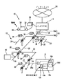
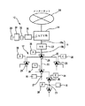
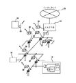
図1および図2を参照して、この発明の一実施例の雑音混入箇所探査システム(以下、単に「探査システム」という。)10は、CATVのケーブル回線12において雑音の混入箇所を探査するのに用いられるものである。なお、図1は、探査システム10をケーブル回線12に装着した状態を示す模式図であり、図2は、その配線図である。
【0012】
ケーブル回線12は、CATV局14と各加入者端末16とを接続するものであり、CATV局14から延びる幹線18と、幹線18から分岐・分配配線された複数の支線20とによって構成されている。なお、このケーブル回線12においては、CATV局14から各加入者端末16へ向かう「下り信号」の伝送帯域として70〜860MHzの帯域が用いられ、各加入者端末16からCATV局14へ向かう「上り信号」の伝送帯域として10〜55MHzの帯域が用いられるものとする。
【0013】
幹線18は、大容量データの高速伝送が可能な光ケーブル18aと同軸ケーブル18bとを光電変換器22を介して接続したものであり、幹線18の光ケーブル18a側がCATV局14を介してインターネット網24に接続され、同軸ケーブル18b側が中継アンプ(増幅器)26を介して支線20に接続されている。支線20は、上流から下流へ向けて中継アンプ26を介しながら順次分岐・分配配線された同軸ケーブルであり、支線20の途中には、分岐器(タップオフ)27が設けられている。そして、分岐器27において分岐された支線(引込み線)20aの末端が各加入者端末16に接続されている。
【0014】
中継アンプ26は、ケーブル回線12を分岐する機能と伝送信号を増幅する機能とを併有するものであり、中継アンプ26には、伝送信号を取り出すためのモニタ端子が設けられている。そして、各中継アンプ26は、支線20を支持する電柱28に取り付けられている。
【0015】
分岐器27は、支線20から各加入者端末16へ信号を分岐するものであり、分岐器27には、支線(引込み線)20aが接続される端子が設けられている。
【0016】
加入者端末16は、「上り信号」の発信源となるものであり、ケーブルモデム16a,パーソナルコンピュータ16b,ホームターミナル(またはセットトップボックス)16cおよびテレビ受像機16d等が加入者端末16に含まれる。
【0017】
ケーブル回線12を構成する同軸ケーブルは、外部からの電波を遮蔽する構造を有するため、通常は、伝送信号に雑音が混入することはない。しかし、同軸ケーブルに傷が付いた場合や、コネクタ等にゆるみがある場合や、同軸ケーブルと加入者端末16との接続方法が不適切であった場合等には、その箇所から無線機器,工場設備または家庭電化製品等で発生した雑音が伝送信号の「上り信号帯域」に混入し、流合雑音の原因となる。そこで、雑音の混入箇所を速やかに探査して補修するために、本実施例の探査システム10が用いられる。
【0018】
探査システム10(図1,図2)は、幹線18に接続された「上流側検出手段」としての監視装置30と、監視装置30にインターフェイス32を介して接続された「比較手段」としてのコンピュータ34と、コンピュータ34に接続された警報装置36と、支線20に接続された「下流側検出手段」としての検出装置38とを含む。
【0019】
「上流側検出手段」としての監視装置30は、「上り信号帯域」の電圧レベルを時間と関連付けて検出する機能を有し、具体的には、周知のスペクトルアナライザが監視装置30として用いられる。
【0020】
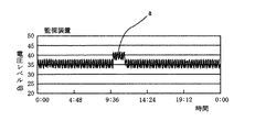
「比較手段」としてのコンピュータ34は、監視装置30や各検出装置38から与えられたデータに基づいて、所定の周波数帯域における電圧レベルと時間との関係をグラフ表示する機能と、電圧レベルが所定の閾値を超えたときに警報信号を出力する機能とを有する。なお、本実施例では、10〜55MHzの帯域が「上り信号」の伝送帯域として用いられているため、コンピュータ34では、この帯域から所定幅(たとえば1〜5MH幅)の特定帯域(たとえば30〜35MHz)が選択され、選択された帯域についての電圧レベルがグラフに採用される。
【0021】
コンピュータ34によって表示されるグラフは、たとえば図5に示すようなものであり、このグラフにおいて、電圧レベルの大きく変動した部分aが不具合を生じさせる雑音である。したがって、「電圧レベルの変動時間」、すなわち「電圧レベルが大幅に増大した時間」または「電圧レベルが大幅に低下した時間」に基づいて雑音を特定することができる。なお、電圧レベルと時間との関係は、図示しない記憶装置に記憶され、必要に応じて取り出される。
【0022】
警報装置36は、コンピュータ34から与えられた警報信号に基づいて、管理者等の端末(電話またはパーソナルコンピュータ等)へ所定の音声またはメールを送信する機能を有する。
【0023】
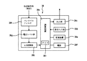
「下流側検出手段」としての検出装置38は、「上り信号帯域」の電圧レベルを時間と関連付けて検出し、かつ、記憶する機能を有する。つまり、検出装置38は、図3に示すように、タイマ38iを内蔵した演算装置38aを含み、演算装置38aには、A/D変換部38b,出力部38c,設定入力部38d,記憶装置38eおよび電源38fが接続される。また、A/D変換部38bには、電圧レベル計38gが接続され、電圧レベル計38gにはバンドパスフィルタ38hが接続される。
【0024】
バンドパスフィルタ38hは、「上り信号」の伝送帯域(10〜55MHz)に含まれる所定幅(たとえば1〜5MH幅)の特定帯域(たとえば30〜35MHz)に属する信号を通過させるものである。バンドパスフィルタ38hの通過帯域は、コンピュータ34によって選択された帯域(たとえば30〜35MHz)と同じに設定される。これは、上流側検出位置と下流側検出位置とで同種の雑音を検出できるようにするためである。なお、バンドパスフィルタ38hの通過帯域は、バンドパスフィルタ38hの設定周波数帯域を変えることによって変更可能である。
【0025】
電圧レベル計38gは、バンドパスフィルタ38hを通過した信号の電圧レベルを計測するものであり、演算装置38aは、各種の演算処理を行うとともに、電圧レベルと時間とを関連付けて記憶装置38eへ書き込むものである。また、設定入力部38dは、電圧レベルの検出開始時間または検出終了時間等を設定するものであり、出力部38cは、記憶装置38e内の各種データをコンピュータ34(図6)へ出力するものである。
【0026】
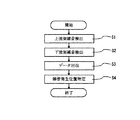
以下には、図4のフロー図に従って、探査システム10を用いて雑音混入箇所を探査する方法について説明する。なお、以下の例では、加入者端末16に含まれるケーブルモデム16aの接続端子16e(図1)が雑音混入箇所であるものとする。
【0027】
この探査方法は、図4に示すように、「上流側雑音検出工程S1」,「下流側雑音検出工程S2」,「データ回収工程S3」および「雑音混入位置特定工程S4」を経て実行される。
【0028】
「上流側雑音検出工程S1」では、まず、監視装置30が幹線18に設定された所定の上流側検出位置に接続される。そして、コンピュータ34が監視装置30に接続され、警報装置36がコンピュータ34に接続される。そして、これらの機器によって幹線18を伝送される信号の「上り信号帯域」の電圧レベルが時間と関連付けて自動検出される。そして、コンピュータ34において、「所定の閾値を超える電圧レベルが検出された」と判断されると、警報装置36から管理者等の端末(電話またはパーソナルコンピュータ)へその旨が通報(音声またはメール)される。
【0029】
なお、本実施例では、監視装置30を設ける位置すなわち上流側検出位置を幹線18に設定しているが、この位置は、後述するように、ケーブル回線12の任意の位置に設定されてもよい。
【0030】
「下流側雑音検出工程S2」では、複数の検出装置38が中継アンプ26を利用して支線20の所定の下流側検出位置に接続される。そして、各検出装置38によって支線20を伝送される信号の「上り信号帯域」の電圧レベルが時間と関連付けて自動検出される。検出装置38の設置箇所は適宜変更可能であるが、本実施例では上流域にある6個の中継アンプ26に対して設置されるものとする。また、検出装置38による検出時間も適宜変更可能であるが、本実施例では「0:00〜0:00」に設定されるものとする。なお、図1および図2では、説明の便宜上、各検出装置38に対してA〜Fの符号を付した。
【0031】
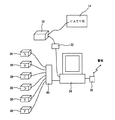
「データ回収工程S3」では、支線20に接続された全ての検出装置38が撤収され、各検出装置38の記憶装置38eに記憶されたデータが回収される。つまり、図6に示すように、支線20から撤収された各検出装置38がインターフェイス40を介してコンピュータ34に接続され、コンピュータ34によって各検出装置38の記憶装置38eからデータが読み取られる。なお、読み取られるデータは、主として電圧レベルと時間とに関するデータである。
【0032】
「雑音混入位置特定工程S4」では、監視装置30および各検出装置38からコンピュータ34へ与えられたデータに基づいて、電圧レベルと時間との関係がグラフ表示される。そして、これらのグラフから「電圧レベルの変動時間」が目視により比較される。なお、コンピュータ34は、「電圧レベルの変動時間」を比較可能な状態(グラフ)にする点において「比較手段」である。
【0033】
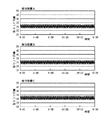
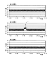
コンピュータ34によって表示されたグラフが、図5,図7および図8に示すようなものであれば、検出装置Eのグラフ(図8)においてのみ電圧レベルの変動が認められる。そして、「電圧レベルの変動時間」を確認すると、混入時が「9:50頃」であり、消滅時が「11:30頃」であり、監視装置のグラフ(図5)における「電圧レベルの変動時間」と一致する。
【0034】
これより、監視装置のグラフ(図5)に現れた雑音aと検出装置Eのグラフ(図8)に現れた雑音bとが同じ箇所から混入していることは明らかであり、その混入箇所は、検出装置Eの下流で、かつ、検出装置Fの下流ではない領域にあることがわかる。したがって、管理者等は、その領域内を詳細に調査することにより、雑音混入箇所を見つけ出すことができる。
【0035】
本実施例によれば、監視装置30のグラフと検出装置A〜Fのグラフとを比較することによって、雑音の伝送ルートを特定でき、雑音混入箇所を低コストで迅速に探査できる。
【0036】
また、「電圧レベルの変動時間」に基づいて雑音を特定するようにしているので、検出装置38の構成を簡素化でき、システム全体のコストを低く抑えることができる。
【0037】
また、検出装置38は、長期間にわたって設けておくことが可能なため、あらゆる態様で混入する雑音に確実に対処できる。
【0038】
なお、上述の実施例では、「データ回収工程S3」において、全ての検出装置38を撤収するようにしているが、たとえば図9に示すように、各検出装置38に通信機能(無線または有線)を持たせることによって、検出装置38を撤収することなく、データのみを回収するようにしてもよい。この場合には、各検出装置38を支線20に対して取り付けたままにしておくことができるので、雑音の混入箇所をより迅速に探査できるとともに、探査コストをより低減できる。
【0039】
また、たとえば図9に示すように、幹線18には、監視装置30に代えて検出装置38を設けてもよい。検出装置38では、監視装置30に比べて機能が限定されるが、「上り信号帯域」の雑音を検出する機能においては同等であり、検出装置38を「上流側検出手段」として用いても特に問題は生じない。
【0040】
また、上述の実施例では、上流側検出位置を幹線18に設定しているが、これを支線20における中継アンプ26のいずれか一つまたは複数に設定してもよい。たとえば、複数系統に分岐されたケーブル回線12においては、各系統の最上流にある中継アンプ26を上流側検出位置とすることで、系統ごとに迅速な対応が可能となる。
【0041】
さらに、検出装置38は、中継アンプ26のモニタ端子の他に、分岐器27の空端子に接続されてもよい。
【0042】
そして、本発明は、上流から下流へ向かって分岐・分配配線された双方向性を持ったケーブル回線に広く適用できるものであり、その適用対象は実施例のCATVに限定されるものではない。
【0043】
【発明の効果】
この発明によれば、上流側検出手段で検出された「電圧レベルの変動時間」と下流側検出手段で検出された「電圧レベルの変動時間」とを比較することによって、雑音の伝送ルートを簡単に特定できる。
【0044】
また、「電圧レベルの変動時間」を検出することによって雑音を特定するようにしているので、汎用の電気部品を組み合わせるだけで、検出手段を安価に製造することができる。
【0045】
そして、検出手段をケーブル回線に対して長期間にわたって設けておくことができ、また、検出手段によって電圧レベルを自動的に検出することができるので、あらゆる態様で混入する雑音に確実に対処できる。
【図面の簡単な説明】
【図1】雑音混入箇所の探査システムをケーブル回線に装着した状態を示す模式図である。
【図2】雑音混入箇所の探査システムをケーブル回線に装着した状態を示す配線図である。
【図3】検出装置を示すブロック図である。
【図4】雑音混入箇所の探査方法を示すフロー図である。
【図5】監視装置が検出した電圧レベルと時間との関係を示すグラフである。
【図6】データの回収方法を示す概念図である。
【図7】検出装置A〜Cが検出した電圧レベルと時間との関係を示すグラフである。
【図8】検出装置D〜Fが検出した電圧レベルと時間との関係を示すグラフである。
【図9】この発明の他の実施例を示す概念図である。
【符号の説明】
10… 雑音混入箇所の探査システム
12… ケーブル回線
14… CATV局
16… 加入者端末
18… 幹線
20… 支線
20… 支線(引込み線)
26… 中継アンプ
30… 監視装置
34… コンピュータ
36… 警報装置
37… 分岐器
38… 検出装置[0001]
TECHNICAL FIELD OF THE INVENTION
BACKGROUND OF THE
[0002]
[Prior art]
When providing a two-way communication service such as an Internet connection service using a CATV line, measures against so-called ingress noise are indispensable.
[0003]
That is, in the CATV line, since the branch line is branched and distributed from the trunk line to each subscriber terminal, in the upward direction (the direction from the subscriber terminal to the CATV station), all the noise mixed into the branch line is lost in the trunk line. And the collected noise (ie, ingress noise) may cause instability of the two-way communication service. Therefore, when ingress noise appears on the main line, it is necessary to immediately search for a source of the noise and repair the source.
[0004]
Therefore, in the related art, a monitoring device is installed in a CATV station to monitor ingress noise, and when ingress noise appears, an investigator traces and identifies a location where the noise is mixed, and repairs the location. Was like that.
[0005]
[Problems to be solved by the invention]
In the past, the location where noise was mixed was searched for by the investigator's follow-up survey. However, this method was not efficient because it relied on the experience and perception of the investigator, and had a problem that the cost was high. In addition, noise is not always mixed, and may be mixed only during a certain time period of the day, or may be mixed only on a certain day of the week. However, it was not possible to cope with the noise mixed in every way.
[0006]
SUMMARY OF THE INVENTION Therefore, a main object of the present invention is to provide a system and a method for searching for a noise-containing portion, which can easily search for a noise-containing portion regardless of the mixing mode.
[0007]
[Means for Solving the Problems]
The invention described in
[0008]
The invention described in claim 2 is a method for searching for a noise-mixed portion, wherein the cable-mixed
[0009]
For example, the
[0010]
Accordingly, the upstream detection means 30 is provided at the upstream detection position, and the downstream detection means 38 is provided at each of the plurality of downstream detection positions, so that the "voltage level fluctuation time" detected by the upstream detection means 30 By comparing the "voltage level fluctuation time" detected by each downstream detection means 38, the transmission route of the noise to be searched can be specified.
[0011]
BEST MODE FOR CARRYING OUT THE INVENTION
Referring to FIG. 1 and FIG. 2, a noise contamination location detecting system (hereinafter, simply referred to as a “detection system”) 10 according to an embodiment of the present invention searches for a noise contamination location in a
[0012]
The
[0013]
The
[0014]
The
[0015]
The
[0016]
The
[0017]
Since the coaxial cable constituting the
[0018]
The exploration system 10 (FIGS. 1 and 2) includes a
[0019]
The
[0020]
The
[0021]
A graph displayed by the
[0022]
The
[0023]
The
[0024]
The band-
[0025]
The
[0026]
In the following, a method of searching for a noise-containing location using the
[0027]
As shown in FIG. 4, this search method is executed through an “upstream noise detection step S1”, a “downstream noise detection step S2”, a “data recovery step S3”, and a “noise mixing position specifying step S4”. .
[0028]
In the “upstream noise detection step S1”, first, the
[0029]
In the present embodiment, the position where the
[0030]
In the “downstream noise detection step S2”, the plurality of
[0031]
In the “data collection step S3”, all the
[0032]
In the “noise mixing position specifying step S4”, the relationship between the voltage level and the time is graphically displayed based on the data provided from the
[0033]
If the graph displayed by the
[0034]
From this, it is clear that the noise a appearing in the graph of the monitoring device (FIG. 5) and the noise b appearing in the graph of the detecting device E (FIG. 8) are mixed from the same place. It can be seen that it is in a region downstream of the detection device E and not downstream of the detection device F. Therefore, the administrator or the like can find out a noise-incorporated portion by examining the area in detail.
[0035]
According to the present embodiment, by comparing the graph of the
[0036]
In addition, since the noise is specified based on the “voltage level fluctuation time”, the configuration of the
[0037]
Further, since the
[0038]
In the above-described embodiment, all the
[0039]
For example, as shown in FIG. 9, a
[0040]
Further, in the above-described embodiment, the upstream detection position is set to the
[0041]
Further, the
[0042]
The present invention can be widely applied to a bidirectional cable line branched and distributed from upstream to downstream, and its application is not limited to the CATV of the embodiment.
[0043]
【The invention's effect】
According to the present invention, the noise transmission route can be simplified by comparing the “voltage level fluctuation time” detected by the upstream detection means with the “voltage level fluctuation time” detected by the downstream detection means. Can be specified.
[0044]
Further, since the noise is specified by detecting the “voltage level fluctuation time”, the detection means can be manufactured at low cost only by combining general-purpose electric components.
[0045]
The detecting means can be provided for the cable line for a long period of time, and the voltage level can be automatically detected by the detecting means, so that noises mixed in all aspects can be dealt with reliably.
[Brief description of the drawings]
FIG. 1 is a schematic diagram showing a state in which a system for searching for a noise-containing location is attached to a cable line.
FIG. 2 is a wiring diagram showing a state in which a system for searching for a place where noise is mixed is attached to a cable line.
FIG. 3 is a block diagram illustrating a detection device.
FIG. 4 is a flowchart showing a method for searching for a noise-containing portion.
FIG. 5 is a graph showing a relationship between a voltage level detected by the monitoring device and time.
FIG. 6 is a conceptual diagram illustrating a data collection method.
FIG. 7 is a graph showing a relationship between voltage levels detected by the detection devices A to C and time.
FIG. 8 is a graph showing a relationship between a voltage level detected by the detection devices DF and time.
FIG. 9 is a conceptual diagram showing another embodiment of the present invention.
[Explanation of symbols]
DESCRIPTION OF SYMBOLS 10: A system for searching for a place where noise is mixed 12: Cable line 14: CATV station 16: Subscriber terminal 18: Main line 20: Branch line 20: Branch line (drop-in line)
26
Claims (2)
前記ケーブル回線に接続され、前記ケーブル回線によって伝送される信号の上り信号帯域の電圧レベルを時間と関連付けて検出する上流側検出手段、
前記ケーブル回線の前記上流側検出手段よりも下流側に接続され、前記ケーブル回線によって伝送される信号の上り信号帯域の電圧レベルを時間と関連付けて検出する下流側検出手段、および
前記上流側検出手段によって検出された前記電圧レベルの変動時間と前記下流側検出手段によって検出された前記電圧レベルの変動時間とを比較する比較手段を備える、雑音混入箇所の探査システム。A noise mixing point detection system for searching for a mixing point of noise mixed in an upstream signal band with respect to a cable line branched and distributed from upstream to downstream,
An upstream detection unit connected to the cable line and detecting a voltage level of an upstream signal band of a signal transmitted by the cable line in association with time.
A downstream detection unit connected downstream of the upstream detection unit of the cable line and detecting a voltage level of an upstream signal band of a signal transmitted by the cable line in association with time, and the upstream detection unit And a comparing means for comparing the fluctuation time of the voltage level detected by the downstream detection means with the fluctuation time of the voltage level detected by the downstream detection means.
(a)前記ケーブル回線によって伝送される信号の上り信号帯域の電圧レベルを前記ケーブル回線の上流側検出位置において時間と関連付けて検出し、
(b)前記ケーブル回線によって伝送される信号の上り信号帯域の電圧レベルを前記ケーブル回線の前記上流側検出位置よりも下流の下流側検出位置において時間と関連付けて検出し、
(c)前記上流側検出位置において検出された前記電圧レベルの変動時間と前記下流側検出位置において検出された前記電圧レベルの変動時間とを比較し、
(d)比較された2つの電圧レベルの変動時間が一致したとき、前記下流側検出位置より下流において雑音が混入したと判定する、雑音混入箇所の探査方法。A method for searching for a noise-mixed portion, wherein the cable mix-and-distribute wiring from upstream to downstream is searched for a mixed portion of noise mixed into an upstream signal band,
(A) detecting a voltage level of an upstream signal band of a signal transmitted by the cable line in association with time at an upstream detection position of the cable line;
(B) detecting a voltage level of an upstream signal band of a signal transmitted by the cable line at a downstream detection position downstream of the upstream detection position of the cable line in association with time;
(C) comparing the fluctuation time of the voltage level detected at the upstream detection position with the fluctuation time of the voltage level detected at the downstream detection position;
(D) A method for searching for a noise-containing portion, wherein it is determined that noise is mixed downstream from the downstream-side detection position when the fluctuation times of the compared two voltage levels match.
Priority Applications (1)
| Application Number | Priority Date | Filing Date | Title |
|---|---|---|---|
| JP2002198938A JP2004040737A (en) | 2002-07-08 | 2002-07-08 | Investigation system for noise mixed part and investigation method |
Applications Claiming Priority (1)
| Application Number | Priority Date | Filing Date | Title |
|---|---|---|---|
| JP2002198938A JP2004040737A (en) | 2002-07-08 | 2002-07-08 | Investigation system for noise mixed part and investigation method |
Publications (1)
| Publication Number | Publication Date |
|---|---|
| JP2004040737A true JP2004040737A (en) | 2004-02-05 |
Family
ID=31706255
Family Applications (1)
| Application Number | Title | Priority Date | Filing Date |
|---|---|---|---|
| JP2002198938A Pending JP2004040737A (en) | 2002-07-08 | 2002-07-08 | Investigation system for noise mixed part and investigation method |
Country Status (1)
| Country | Link |
|---|---|
| JP (1) | JP2004040737A (en) |
Cited By (2)
| Publication number | Priority date | Publication date | Assignee | Title |
|---|---|---|---|---|
| JP2010081173A (en) * | 2008-09-25 | 2010-04-08 | Jcn Kanto Ltd | Noise source detection device, information providing system and noise source detection method |
| US9401762B2 (en) | 2013-12-03 | 2016-07-26 | International Business Machines Corporation | Identifying a location in a network where noise is generated |
-
2002
- 2002-07-08 JP JP2002198938A patent/JP2004040737A/en active Pending
Cited By (4)
| Publication number | Priority date | Publication date | Assignee | Title |
|---|---|---|---|---|
| JP2010081173A (en) * | 2008-09-25 | 2010-04-08 | Jcn Kanto Ltd | Noise source detection device, information providing system and noise source detection method |
| US9401762B2 (en) | 2013-12-03 | 2016-07-26 | International Business Machines Corporation | Identifying a location in a network where noise is generated |
| US9912405B2 (en) | 2013-12-03 | 2018-03-06 | International Business Machines Corporation | Identifying a location in a network where noise is generated |
| US9948390B2 (en) | 2013-12-03 | 2018-04-17 | International Business Machines Corporation | Identifying a location in a network where noise is generated |
Similar Documents
| Publication | Publication Date | Title |
|---|---|---|
| US5990687A (en) | Measuring shield breaks in coaxial cable by a sheath test current | |
| US6915530B1 (en) | Ingress detection and characterization by time/frequency map | |
| US9774847B2 (en) | Dual-port testing of a cable network | |
| US10110888B2 (en) | Icon-based home certification, in-home leakage testing, and antenna matching pad | |
| WO2001078391A2 (en) | Distortion monitoring system for catv transmission networks | |
| US11201639B2 (en) | Instruments and methods of detecting intermittent noise in a cable network system | |
| EP3149863B1 (en) | A surge protector for a transceiver | |
| US20140082686A1 (en) | Characterizing ingress noise | |
| JPH05122170A (en) | Abnormality monitoring device for outdoor receiving equipment | |
| JP2004040737A (en) | Investigation system for noise mixed part and investigation method | |
| US7112968B1 (en) | Method and apparatus for detecting a partial discharge in a high-voltage transmission and distribution system | |
| CN109788273A (en) | A kind of failure self-detection method of satellite TV system | |
| JP2002016898A (en) | Bidirectional CATV system, transmission line equipment, center equipment | |
| EP3903432B1 (en) | Systems, devices and methods for detection and/or prevention of power line communication | |
| CN109587473A (en) | A kind of self detection device of the failure of satellite TV system | |
| US8724681B2 (en) | Ingress noise localization in a cable network | |
| US12556300B2 (en) | Systems, devices and methods for detection and/or prevention of power line communication | |
| JP4601696B2 (en) | Noise source detection apparatus, information providing system, and noise source detection method | |
| JP5661425B2 (en) | Inflow noise detection apparatus and CATV system | |
| JP2004072477A (en) | Upstream ingress noise detection system in CATV facilities | |
| US11677439B2 (en) | Method and apparatus providing common path distortion (CPD) detection from a field instrument | |
| JP5805165B2 (en) | Broadcast system | |
| JPH06284092A (en) | Light amplification relay transmission system | |
| JP2002064804A (en) | Device for detecting abnormality in community reception system | |
| JPH01117433A (en) | Optical cable system monitor system |
Legal Events
| Date | Code | Title | Description |
|---|---|---|---|
| A621 | Written request for application examination |
Free format text: JAPANESE INTERMEDIATE CODE: A621 Effective date: 20050613 |
|
| A977 | Report on retrieval |
Free format text: JAPANESE INTERMEDIATE CODE: A971007 Effective date: 20071228 |
|
| A131 | Notification of reasons for refusal |
Free format text: JAPANESE INTERMEDIATE CODE: A131 Effective date: 20080115 |
|
| A02 | Decision of refusal |
Free format text: JAPANESE INTERMEDIATE CODE: A02 Effective date: 20080520 |