JP2004040728A - Piezoelectric speaker arrangement - Google Patents
Piezoelectric speaker arrangement Download PDFInfo
- Publication number
- JP2004040728A JP2004040728A JP2002198821A JP2002198821A JP2004040728A JP 2004040728 A JP2004040728 A JP 2004040728A JP 2002198821 A JP2002198821 A JP 2002198821A JP 2002198821 A JP2002198821 A JP 2002198821A JP 2004040728 A JP2004040728 A JP 2004040728A
- Authority
- JP
- Japan
- Prior art keywords
- diaphragm
- piezoelectric
- piezoelectric element
- speaker device
- piezoelectric speaker
- Prior art date
- Legal status (The legal status is an assumption and is not a legal conclusion. Google has not performed a legal analysis and makes no representation as to the accuracy of the status listed.)
- Pending
Links
- 230000005484 gravity Effects 0.000 claims description 4
- 230000005236 sound signal Effects 0.000 description 16
- 238000010586 diagram Methods 0.000 description 10
- 230000002093 peripheral effect Effects 0.000 description 8
- 239000013585 weight reducing agent Substances 0.000 description 6
- XEEYBQQBJWHFJM-UHFFFAOYSA-N Iron Chemical group [Fe] XEEYBQQBJWHFJM-UHFFFAOYSA-N 0.000 description 4
- 239000011347 resin Substances 0.000 description 4
- 229920005989 resin Polymers 0.000 description 4
- 239000003990 capacitor Substances 0.000 description 3
- JRPBQTZRNDNNOP-UHFFFAOYSA-N barium titanate Chemical compound [Ba+2].[Ba+2].[O-][Ti]([O-])([O-])[O-] JRPBQTZRNDNNOP-UHFFFAOYSA-N 0.000 description 2
- 229910002113 barium titanate Inorganic materials 0.000 description 2
- 230000000694 effects Effects 0.000 description 2
- 238000009434 installation Methods 0.000 description 2
- 229910052742 iron Inorganic materials 0.000 description 2
- 238000000465 moulding Methods 0.000 description 2
- LJCNRYVRMXRIQR-OLXYHTOASA-L potassium sodium L-tartrate Chemical compound [Na+].[K+].[O-]C(=O)[C@H](O)[C@@H](O)C([O-])=O LJCNRYVRMXRIQR-OLXYHTOASA-L 0.000 description 2
- 235000011006 sodium potassium tartrate Nutrition 0.000 description 2
- 239000000126 substance Substances 0.000 description 2
- 230000015572 biosynthetic process Effects 0.000 description 1
- 230000035945 sensitivity Effects 0.000 description 1
- 239000000725 suspension Substances 0.000 description 1
- 238000003786 synthesis reaction Methods 0.000 description 1
Images
Landscapes
- Piezo-Electric Transducers For Audible Bands (AREA)
Abstract
Description
【0001】
【発明の属する技術分野】
本発明は、圧電素子を用いた圧電型スピーカ装置に関する。
【0002】
【従来の技術】
従来、スピーカ装置として、ダイナミック型スピーカや圧電型スピーカが知られている。ダイナミック型スピーカは、例えばコーン形状を有する振動板に固定された駆動コイルを磁気回路の磁気空隙内に配し、磁気空隙内の直流磁界によって得られるコイルの電磁駆動力を機械振動として振動板に伝えることにより、振動板がこの機械振動を音響変換して放音することができる。
【0003】
一方、圧電型スピーカはロッシェル塩やチタン酸バリウムなどの圧電物質による圧電効果を利用したものであり、例えば、特開2000−354297号公報には、圧電素子の中央部にコーン振動板が固着されたスピーカ装置が開示されている。圧電型スピーカはダイナミック型スピーカ装置と異なり磁気回路が不要であるため、軽量なスピーカ装置を得ることができる。上記公報に開示されているように、圧電スピーカ装置はとくにトゥイータ(高音用スピーカ)として適した性能を有している。
【0004】
【発明が解決しようとする課題】
ところで、車載用オーディオ装置のドアマウント用ダイナミック型スピーカ装置においては、ダイナミック型スピーカ装置はドアの下部に取り付けられるので、高音域の音声が乗車した人間の頭部にむけられていないため、人間に対する高音域の音声に対する感度が低下し、臨場感ある音声を楽しめないことが問題となっている。ドアの下部に取り付けられたダイナミック型スピーカ装置を、乗車した人間の方向にむければ良いのであるが、ドアの構造、車内スペース、コスト等の問題がある。また、ダイナミック型スピーカ装置をドアの上部に取り付ければ指向性は改善されるが、ドアの構造上の制約、車両の構造の制約によりドアの上部に取り付けることが一般には難しいといった課題があった。
【0005】
【課題を解決するための手段】
請求項1に記載のスピーカ装置の発明は、互いに結合された第1の振動板および第2の振動板と、前記第1の振動板および前記第2の振動板にそれぞれ取り付けられた第1の圧電素子および第2の圧電素子と、を備え、前記第1の振動板および前記第2の振動板の振動方向は互いに非平行とされていることを特徴とする。
【0006】
【発明の実施の形態】
−第1の実施形態−
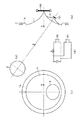
以下、図1を参照して、本発明による圧電型スピーカ装置の第1の実施形態について説明する。図1(a)は第1の実施形態の圧電型スピーカ装置を示す断面図、図1(b)は第1の実施形態の振動板2を示す上面図、図1(c)は第1の実施形態の圧電型スピーカ装置を示す上面図、図1(d)は第1の実施形態の圧電型スピーカ装置を駆動する際に使用するネットワーク回路を示す回路図である。
【0007】
図1(a)に示すように、第1の実施形態の圧電型スピーカ装置は、円板状の第1の圧電素子100と、第1の圧電素子100よりも径の小さい円板状の第2の圧電素子101と、第1の圧電素子100の中央部に取り付けられたコーン状の第1の振動板1と、第2の圧電素子101の中央部に取り付けられたコーン状の第2の振動板2とを備える。第1の振動板1および第2の振動板2は紙あるいは薄い樹脂シート等により構成することができる。また、振動板1と2は一体成形によりあるいは各振動板を別体に成形してこれを接着などにより結合するようにして構成する。
【0008】
第1の圧電素子100および第2の圧電素子101はロシェル塩やチタン酸バリウムなどの圧電物質による圧電効果を利用した容量性のインピーダンスを有する圧電素子である。
【0009】
第2の圧電素子101の中央部にはコーン状の第2の振動板2が取り付けられ、その外周縁の一部分(図1(a)中下部)が第1の振動板1の所定部分(図1(a)中下部)に近接するような位置で第1の振動板1と結合または一体成形されている。第1の振動板1の周辺部は取り付け部材3に取り付けられ固定されている。なお、第1の振動板1は柔軟なエッジ部材1aを介して取り付け部材3に取り付けられているため、とくにエッジ部材1aが容易に弾性変形する。このため第1の振動板1の振動が阻害されることがない。
【0010】
図1(b)は振動板1に結合または一体成形されている第2の振動板2を一点鎖線4の方向から見た振動板2の上面図である。つまり、第2の振動板2の中心部を通り第2の圧電素子101の円板面に垂直な軸方向から見た図であり、第2の振動板2は円形であることがわかる。また、図1(c)は第1の振動板1を一点鎖線5の方向から見た振動板1の上面図である。つまり、第1の振動板1の中心部を通り第1の圧電素子100の円板面に垂直な軸方向から見た図であり、第1の振動板1は円形であることがわかる。
【0011】
一点鎖線5の方向からは、振動板2を斜めに見ることになるため、図1(c)では、振動板2は楕円形に描かれることになる。
【0012】
第1の圧電素子100および第2の圧電素子101は図1(d)に示すネットワーク回路を介して駆動されてもよい。第1の圧電素子100の電極にはインダクタLが直列に接続されたローパスフィルタを介して音声信号が加えられる。このため、第1の圧電素子100には低域の音声信号が、第2の圧電素子101には全域の音声信号がそれぞれ印加される。
【0013】
次に、第1の実施形態の圧電型スピーカ装置の動作について説明する。第1の圧電素子100および第2の圧電素子101に音声信号を供給すると、取り付け部材3により支持された第1の圧電素子100は中央部が図1(a)において左右方向に、すなわち一点鎖線5と平行方向に振動するように変形する。また、第2の圧電素子101は一点鎖線4と平行方向に振動するように変形する。第1の振動板1は第1の圧電素子100の振幅によって駆動され、第1の振動板1から効率的に主に低音域の音声が放出される。
【0014】
また、第2の振動板2は第2の圧電素子101の振幅によって駆動され、第2の振動板2から効率的に主に高音域の音声が一点鎖線4と平行方向に放出される。すなわち、取り付け部材3は自動車の側面ドア内壁そのもの、あるいは自動車の側面ドア内壁に取り付けられることにより、図1(a)における一点鎖線4の左上方向は、車両に乗車している人間の頭部を指す方向となる。したがって、第2の圧電素子101に取り付けられた第2の振動板2から放出される高音域の音声が人間の耳に効率よく到達する。高音域では指向性が狭いため、本実施形態のように車に座っている人間の頭部にスピーカの振動面が向くように構成することにより、高音域を効率よく聞くことができるのでよりよい音声を聞くことができるようになった。
【0015】
また、圧電型スピーカは従来のダイナミック型スピーカより軽いので、軽量化が要求される車載用途には好適である。
【0016】
第1の実施形態では、ネットワーク回路を用いて第1の圧電素子100に低音領域を、受け持たせるようにしている。この回路において、第2の圧電素子101にさらに積極的に高音領域を受け持たせるために、ハイパスフィルター(コンデンサなど)をネットワーク回路に設けてもよい。
【0017】
以上述べたように、本実施形態の圧電型スピーカ装置を車載用のドアマウント用スピーカに適用すれば、スピーカはドアの下部に取り付けても高音領域は乗車している人間の頭部に向かって放射される。
【0018】
しかも、圧電型スピーカは薄型、軽量なので、ドアに取り付けることは容易であり、車載用オーディオ装置に対する軽量化の要請にも応えうるスピーカとなる。
−第2の実施形態−
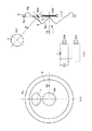
以下、図2を参照して、本発明による圧電型スピーカ装置の第2の実施形態について説明する。図2(a)は第2の実施形態の圧電型スピーカ装置を示す断面図、図2(b)は第2の実施形態の振動板7を示す上面図、図2(c)は第2の実施形態の圧電型スピーカ装置を示す上面図、図2(d)は第2の実施形態の圧電型スピーカ装置を駆動する際に使用するネットワーク回路を示す回路図である。
【0019】
図2(a)に示すように、第2の実施形態の圧電型スピーカ装置は、円板状の第1の圧電素子200と、第1の圧電素子200よりも径の小さい円板状の第2の圧電素子201と、第1の圧電素子200の中央部に取り付けられた第1の振動板6と、第1の振動板6の外周縁側に設けたエッジ部材6aと、を備える。エッジ部材6aの外周の周辺は取り付け部材8に取り付けられる。取り付け部材8は例えば自動車のドアその他のフレームや筐体などにより構成される。
【0020】
第1の振動板6は、第1の圧電素子200の中央部が取り付けられる第1の圧電素子200の面から離間する方向(図2(a)中左方向)に、第1の圧電素子200の中央部から拡大するコーン部6bと、このコーン部6bの外周縁から折り返して形成され、前記第1の圧電素子200の面に接近する方向(図2(a)中右方向)に、コーン部6bの外周縁から拡大する折り返し部11を備える。コーン部6bの中央部すなわち第1の振動板6の基端部に第1の圧電素子200を取り付ける。また、第2の圧電素子201の中央部にはコーン状の第2の振動板7が取り付けられ、その外周縁の一部分(図2(a)中上部)が第1の振動板1の折り返し部11における所定部分(図1(a)中上部)に近接するような位置で第1の振動板6と結合または一体成形されている。
【0021】
第1の圧電素子200、第2の圧電素子201、第1の振動板6、第2の振動板7及びエッジ部材6a全体の重心Gの位置は、一点鎖線10の方向(第1の振動板6の中心部を通り第1の圧電素子200の円板面に垂直な軸方向)において、鎖線12上で示す取り付け部材8の表面8aの面とほぼ一致する位置になるように取り付けられる。なお、第1振動板6および第2の振動板7は紙あるいは薄い樹脂シート等により構成することができる。
【0022】
図2(b)は振動板6に接着または一体成形されている振動板7を一点鎖線9の方向(第2の振動板7の中心部を通り第2の圧電素子201の円板面に垂直な軸方向)から見た第2の振動板7の上面図であり、円形であることがわかる。また、図2(c)は第1の振動板6を一点鎖線10の方向から見た上面図であり、第1の振動板も円形であることがわかる。一点鎖線10の方向からは、振動板7を斜めに見ることになるため、図2(c)では、振動板7は楕円形に描かれることになる。
【0023】
第1の圧電素子200および第2の圧電素子201は図2(d)に示すネットワーク回路を介して駆動されてもよい。第1の圧電素子200の電極にはインダクタLが直列に接続されたローパスフィルタを介して音声信号が加えられる。このため、第1の圧電素子200には低域の音声信号が、第2の圧電素子201には高域の音声信号がそれぞれ主に印加される。
【0024】
次に、第2の実施形態の圧電型スピーカ装置の動作について説明する。第1の圧電素子200および第2の圧電素子201に音声信号を供給すると、取り付け部材8により支持された第1の圧電素子200は中央部が図2(a)において左右方向に、すなわち一点鎖線10と平行方向に振動するように変形する。また、第2の圧電素子201は一点鎖線7と略平行方向に振動するように変形する。第1の振動板6は第1の圧電素子200の振幅によって駆動され、第1の振動板1から効率的に主に低音域の音声が放出される。また、第2の振動板7は第2の圧電素子201の振幅によって駆動され、第2の振動板7から効率的に主に高音域の音声が一点鎖線9と略平行方向に放出される。したがって、取り付け部材8を自動車の側面ドア内壁そのものにしたり、自動車の側面ドア内壁にとりつけることにより、図2(a)における一点鎖線9の左上方向は、車に乗車している人間の頭部を指す方向となる。したがって、第2の圧電素子201に取り付けられた振動板7から放出される高音域の音声が人間の耳に効率よく到達する。
【0025】
第2の実施形態では、第1の振動板6は、コーン部6bとこのコーン部6bから折り返してコーン部6bの広がり方向と逆方向に広がる折り返し部11を備えることにより一点鎖線10の方向に対して厚みを薄くできる。また、重心位置Gを一点鎖線10の方向において取り付け部材8の表面8aの面とほぼ一致する位置になるように取り付けられるので、第1、第2の振動板6、7などにダンパーなどのエッジとは別なサスペンションを設けることを要しない。このため、取り付け部材8を使用せず、圧電スピーカ装置をドアの鉄板に直接貼り付けることができ、第2の実施形態の圧電型スピーカの設置スペースが小さくなり、容易に取り付けることができるようになる。
【0026】
また、圧電型スピーカは従来のダイナミック型スピーカより軽いので、軽量化が要求される車載用途には好適である。さらに前述したように、高音域では指向性が高いため、本実施形態のように車に座っている人間の頭部にスピーカの振動面が向くように構成することにより、高音域を効率よく聞くことができるのでよりよい音声を聞くことができるようになる。
【0027】
第2の実施形態では、ネットワーク回路を用いて第1の圧電素子200に低域を、受け持たせるようにしている。この回路において、第2の圧電素子201にさらに積極的に高音領域を受け持たせるために、ハイパスフィルター(コンデンサなど)をネットワーク回路に設けてもよい。
【0028】
以上のように本実施形態の圧電型スピーカ装置は、第1の振動板6をコーン部とそこから折り返してなる折り返し部より構成し、第1の圧電素子200をコーン部の中央部である基端部に第1の振動板6の内側から取り付けられているため、最小限の部材で第1の振動板6に直接、第1、第2の圧電素子200、201および第2の振動板7を安定して支持できるので、薄型化、軽量化、及びコストダウン化を図れる。
−第3の実施形態−
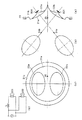
以下、図3を参照して、本発明による圧電型スピーカ装置の第3の実施形態について説明する。図3(a)は第3の実施形態の圧電型スピーカ装置を示す断面図、図3(b)は第3の実施形態の振動板22a、22b示す上面図、図3(c)は第3の実施形態の圧電型スピーカ装置を示す上面図、図3(d)は第3の実施形態の圧電型スピーカ装置を駆動する際に使用するネットワーク回路を示す回路図、である。
【0029】
図3(a)に示すように、第3の実施形態の圧電型スピーカ装置は、円板状の第1の圧電素子300と、円板上の第2の圧電素子301と、第1の振動板22aと、第1の振動板22bと、コーン状の振動板21aと、エッジ部材21bと、取り付け部材23とを備える。第1の振動板22a、第2の振動板22aおよび振動板21aは、紙あるいは薄い樹脂シート等により構成することができる。
【0030】
コーン振動板21aの周辺部は取り付け部材23に取り付けられ固定されている。なお、振動板21aは柔軟なエッジ部材21bを介して取り付け部材23に取り付けられているため、とくにエッジ部材21bが容易に弾性変形する。このため振動板21aの振動が阻害されることがない。
【0031】
図3(b)はコーン振動板21aに接着あるいは一体成形されている第1の振動板22aを一点鎖線24aの方向(第1の振動板22aの中心部を通り第1の圧電素子300の円板面に垂直な軸方向)から見た振動板22aの上面図、および振動板21aに接着されている振動板22bを一点鎖線24bの方向(第2の振動板22bの中心部を通り第2の圧電素子301の円板面に垂直な軸方向)から見た振動板22bの上面図である。この実施形態では振動板22aと22bは楕円形状としてある。また、図3(c)はコーン振動板21aを一点鎖線25の方向(コーン振動板21aの中央部を通る駆動方向)から見た振動板21a、第1、第2の振動板22a、振動板22bの上面図である。同図より、第1、第2の振動板22a、振動板22bはコーン振動板21aの上下対象の位置に取り付けられている。なお、一点鎖線25の方向からは、振動板22aおよび振動板22bを斜めに見ることになるため、図3(c)では、振動板22aおよび22bは、図3(b)に比べより扁平な楕円形に描かれることになる。
【0032】
第1の圧電素子300および第2の圧電素子301は図3(d)に示すネットワーク回路を介して駆動される。第1の圧電素子300の電極にはインダクタLが直列に接続されたローパスフィルタを介して音声信号が加えられる。このため、第1の圧電素子300には低域の音声信号が、第2の圧電素子301には高域の音声信号がそれぞれ主に印加される。
【0033】
次に、第3の実施形態の圧電型スピーカ装置の動作について説明する。第1の圧電素子300および第2の圧電素子301に音声信号を供給すると、第1の振動板22aにより支持された第1の圧電素子300は中央部が図3(a)において、一点鎖線24aと平行方向に振動するように変形する。また、第2の圧電素子301は一点鎖線24bと平行方向に振動するように変形する。第2の振動板22bは第2の圧電素子301の振幅によって駆動され、第2の振動板22bから効率的に主に高音域の音声が一点鎖線24bと平行方向に放出される。すなわち、取り付け部材23が自動車の側面ドア内壁そのもの、あるいは自動車の側面ドア内壁にとりつけられることにより、図3(a)における一点鎖線24bの左上方向は、車に乗車している人間の頭部を指す方向となる。したがって、第2の圧電素子301に取り付けられた振動板22bから放出される高音域の音声が人間の耳に効率よく到達する。高音域では指向性が高いため、本実施形態のように車に座っている人間の頭部にスピーカの振動面が向くように構成することにより、高音域を効率よく聞くことができるのでよりよい音声を聞くことができるようになる。
【0034】
一方、第1の振動板22aは第1の圧電素子300の振幅によって駆動され、第1の振動板22aから効率的に主に低音域の音声が一点鎖線24aと平行方向に放出される。すなわち、取り付け部材23が自動車の側面ドア内壁そのもの、あるいは自動車の側面ドア内壁にとりつけられることにより、図3(a)における一点鎖線24aの左下方向の車に乗車している人間の脚部を指す方向となる。圧電素子300からはもっぱら低音域に対する音声が放出される。低音域の音声は指向性が高くないので、下方に向けても車内では十分に聞きとる事ができる。
【0035】
また、圧電型スピーカは従来のダイナミック型スピーカより軽いので、軽量化が要求される車載用途には好適である。
【0036】
第3の実施形態では、ネットワーク回路を用いて第1の圧電素子300に低域を、受け持たせるようにしている。この回路において、第2の圧電素子301にさらに積極的に高音領域を受け持たせるために、ハイパスフィルター(コンデンサなど)をネットワーク回路に設けてもよい。
【0037】
以上述べたように、本実施形態の圧電型スピーカ装置を車載用のドアマウント用スピーカに適用すれば、スピーカはドアの下部に取り付けても高音領域は乗車している人間の頭部に向かって放射される。
しかも、圧電型スピーカは薄型、軽量なので、ドアに取り付けることは容易であり、車載用オーディオ装置に対する軽量化の要請にも応えうるスピーカとなる。
−第4の実施形態−
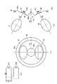
以下、図4を参照して、本発明による圧電型スピーカ装置の第4の実施形態について説明する。図4(a)は第4の実施形態の圧電型スピーカ装置を示す断面図、図4(b)は第4の実施形態の振動板37、38を示す上面図、図4(c)は第4の実施形態の圧電型スピーカ装置を示す上面図、図4(d)は第4の実施形態の圧電型スピーカ装置を駆動する際に使用するネットワーク回路を示す回路図である。
【0038】
図4(a)に示すように、第4の実施形態の圧電型スピーカ装置は、円板状の第1の圧電素子401と、円板状の第2の圧電素子400と、第1の圧電素子401に取り付けられたコーン状の第1の振動板38と、第2の圧電素子400に取り付けられたコーン状の第2の振動板37と、振動板36と、振動板36の外周縁側に設けたエッジ部材36aと、を備える。エッジ部材36aの外周の周辺は取り付け部材39に取り付けられる。取り付け部材39は例えば自動車のドアその他のフレームや筐体などにより構成される。コーン状の振動板36は、図2に示す第2の実施形態と同様に、コーン部36bとこのコーン部36bから折り返してコーン部36bの広がり方向と逆方向に広がる折り返し部43を備え、第1、第2の振動板38、37は振動板36に接着または一体成形されている。
第1、第2の振動板38、37および振動板36は紙あるいは薄い樹脂シート等により構成することができる。
【0039】
図4(b)は第2の振動板37を一点鎖線41の方向(第2の振動板37の中心部を通り第2の圧電素子400の円板面に垂直な軸方向)から見た振動板37の上面図および、第1の振動板38を一点鎖線42の方向(第1の振動板38の中心部を通り第1の圧電素子401の円板面に垂直な軸方向)から見た振動板38の上面図である。この実施例では振動板37および振動板38は楕円形としてある。図4(c)は、振動板36を一点鎖線40の方向(振動板36の中央部を通る駆動方向)から見た振動板36の上面図である。同図より、振動板36は円形であり、第1、第2の振動板38、振動板37はコーン振動板36の上下対象の位置に取り付けられている。なお、振動板36のコーン部36bと折り返し部分43は円形であることがわかる。一点鎖線40の方向からは、振動板37および振動板38を斜めに見ることになるため、図4(c)では、振動板37および38は図4(b)に比べより扁平な楕円形に描かれることになる。
【0040】
第1の圧電素子401および第2の圧電素子400は図4(d)に示すネットワーク回路を介して駆動されてもよい。第1の圧電素子401の電極にはインダクタLが直列に接続されたローパスフィルタを介して音声信号が加えられる。このため、第1の圧電素子401には低域の音声信号が、第2の圧電素子400には低域から高域の音声信号がそれぞれ主に印加される。
【0041】
次に、第4の実施形態の圧電型スピーカ装置の動作について説明する。第1の圧電素子401および第2の圧電素子400に音声信号を供給すると、第1の圧電素子401は中央部が、すなわち一点鎖線42と略平行方向に振動するように変形する。また、第2の圧電素子400は一点鎖線41と略平行方向に振動するように変形する。第1の振動板38は第1の圧電素子401の振幅によって駆動され、第2の振動板38からはローパスフィルタがある場合、効率的に主に低音域の音声が放出される。また、第1の振動板37は第2の圧電素子400の振幅によって駆動され、第1の振動板37からは低音域から高音域までの音声が一点鎖線41と略平行方向に放出される。すなわち、取り付け部材39は自動車の側面ドア内壁そのもの、あるいは自動車の側面ドア内壁にとりつけられることにより、図4(a)における一点鎖線41が向かう左上方向は、車に乗車している人間の頭部を指す方向となる。したがって、第2の圧電素子400に取り付けられた振動板37から放出される高音域の音声が人間の耳に効率よく到達する。低音域では、振動板37と38の振動方向がベクトル合成され、一点鎖線40と平行方向に放出される。
【0042】
第4の実施形態では、第1、第2振動板401、400と結合あるいは一体成形されて取り付け部材39に支持する振動板36は、コーン部36bとそこから折り返してなる折り返し部43より構成することにより一点鎖線40の方向に厚みを薄くできる。このため、取り付け部材39を車のドアの鉄板に直接貼り付けた場合に、第4の実施形態の圧電型スピーカの設置スペースが小さくなり、容易に取り付けることができるようになる。
【0043】
また、圧電型スピーカは従来のダイナミック型スピーカより軽いので、軽量化が要求される車載用途には好適である。さらに前述したように、高音域では指向性が狭いため、本実施形態のように車に座っている人間の頭部にスピーカの振動面が向くように構成することにより、高音域を効率よく聞くことができるのでよりよい音声を聞くことができるようになった。
【0044】
第4の実施形態では、ネットワーク回路を用いて第1の圧電素子400に低域を、受け持たせるようにしている。また、この実施形態では、低音は2つの圧電素子により出力される音がベクトル合成により加算されて放出されるため、2つの圧電素子に対して同じ帯域の低域信号を加えるようにしてもよい。
【0045】
以上のように本実施形態の圧電型スピーカ装置は、コーン部36bとそこから折り返してなる折り返し部43の振動板36を用いて、コーン型振動板36の内側に第1の振動板38に取り付けられる第1の圧電素子401と、第2の振動板37に取り付けられる第2の圧電素子400を備える。これにより、最小限の部材で振動板36に直接、第1の圧電素子401を備えた第1の振動板38と、第2の圧電素子400を備えた第2の振動板37を安定して支持できるので、薄型化、軽量化、及びコストダウン化を図れる。
【0046】
第1の実施形態から第4の実施形態では、2つの圧電型スピーカを取り付けた場合を示したが、圧電型スピーカは3つ以上取り付けることも可能である。また、この場合には3つ以上の周波数帯域をそれぞれの圧電型スピーカに分担して受け持たせることも可能である。
【0047】
以上のように、本発明にかかる実施形態によれば、薄型で軽量のスピーカ装置を構成することができる。また、所望の指向特性を得ることができる。
【図面の簡単な説明】
【図1】本発明による圧電型スピーカ装置の第1の実施形態。
(a)は第1の実施形態の圧電型スピーカ装置を示す断面図、
(b)は第1の実施形態の振動板2を示す上面図、
(c)は第1の実施形態の圧電型スピーカ装置を示す上面図、
(d)は第1の実施形態の圧電型スピーカ装置を駆動する際に使用するネットワーク回路を示す回路図である。
【図2】本発明による圧電型スピーカ装置の第2の実施形態。
(a)は第2の実施形態の圧電型スピーカ装置を示す断面図、
(b)は第2の実施形態の振動板7を示す上面図、
(c)は第2の実施形態の圧電型スピーカ装置を示す上面図、
(d)は第2の実施形態の圧電型スピーカ装置を駆動する際に使用するネットワーク回路を示す回路図である。
【図3】本発明による圧電型スピーカ装置の第3の実施形態。
(a)は第3の実施形態の圧電型スピーカ装置を示す断面図、
(b)は第3の実施形態の振動板22a、22bを示す上面図、
(c)は第3の実施形態の圧電型スピーカ装置を示す上面図、
(d)は第3の実施形態の圧電型スピーカ装置を駆動する際に使用するネットワーク回路を示す回路図である。
【図4】本発明による圧電型スピーカ装置の第4の実施形態。
(a)は第4の実施形態の圧電型スピーカ装置を示す断面図、
(b)は第4の実施形態の振動板37、38を示す上面図、
(c)は第4の実施形態の圧電型スピーカ装置を示す上面図、
(d)は第4の実施形態の圧電型スピーカ装置を駆動する際に使用するネットワーク回路を示す回路図である。
【符号の説明】
100、200、300、401:第1の圧電素子
101、201、301、400:第2の圧電素子
1、6、22a、38:第1の振動板
2、7、22b、37:第2の振動板
3、8、23、39:取り付け部材
1a、6a、21b、36a、:エッジ部材
L:インダクタ
G:重心[0001]
TECHNICAL FIELD OF THE INVENTION
The present invention relates to a piezoelectric speaker device using a piezoelectric element.
[0002]
[Prior art]
Conventionally, dynamic speakers and piezoelectric speakers have been known as speaker devices. In a dynamic speaker, for example, a drive coil fixed to a diaphragm having a cone shape is arranged in a magnetic gap of a magnetic circuit, and the electromagnetic driving force of the coil obtained by a DC magnetic field in the magnetic gap is applied to the diaphragm as mechanical vibration. By transmitting the information, the diaphragm can acoustically convert the mechanical vibration to emit sound.
[0003]
On the other hand, a piezoelectric speaker utilizes the piezoelectric effect of a piezoelectric substance such as Rochelle salt or barium titanate. For example, Japanese Patent Application Laid-Open No. 2000-354297 discloses that a cone diaphragm is fixed to the center of a piezoelectric element. A speaker device is disclosed. Unlike a dynamic speaker device, a piezoelectric speaker does not require a magnetic circuit, so that a lightweight speaker device can be obtained. As disclosed in the above publication, the piezoelectric speaker device has performance particularly suitable as a tweeter (loud speaker).
[0004]
[Problems to be solved by the invention]
By the way, in a dynamic speaker device for a door mount of an in-vehicle audio device, since the dynamic speaker device is attached to a lower portion of a door, high-range sound is not directed to the head of the occupant. There is a problem that the sensitivity to the sound in the high-frequency range is reduced, and it is not possible to enjoy the sound with a sense of reality. It is sufficient if the dynamic speaker device attached to the lower part of the door is directed toward the occupant, but there are problems such as the structure of the door, the space in the vehicle, and the cost. Further, if the dynamic speaker device is mounted on the upper part of the door, the directivity can be improved. However, there is a problem that it is generally difficult to mount the dynamic speaker device on the upper part of the door due to restrictions on the structure of the door and the structure of the vehicle.
[0005]
[Means for Solving the Problems]
The speaker device according to the first aspect of the present invention includes a first diaphragm and a second diaphragm coupled to each other, and a first diaphragm attached to the first diaphragm and the second diaphragm respectively. A piezoelectric element and a second piezoelectric element, wherein the vibration directions of the first diaphragm and the second diaphragm are not parallel to each other.
[0006]
BEST MODE FOR CARRYING OUT THE INVENTION
-1st Embodiment-
Hereinafter, a first embodiment of a piezoelectric speaker device according to the present invention will be described with reference to FIG. FIG. 1A is a cross-sectional view illustrating a piezoelectric speaker device according to the first embodiment, FIG. 1B is a top view illustrating the diaphragm 2 according to the first embodiment, and FIG. FIG. 1D is a top view illustrating the piezoelectric speaker device according to the embodiment, and FIG. 1D is a circuit diagram illustrating a network circuit used when driving the piezoelectric speaker device according to the first embodiment.
[0007]
As shown in FIG. 1A, the piezoelectric speaker device according to the first embodiment includes a first
[0008]
The first
[0009]
A second diaphragm 2 having a cone shape is attached to the center of the second
[0010]
FIG. 1B is a top view of the vibration plate 2 when the second vibration plate 2 combined with or integrally formed with the
[0011]
Since the diaphragm 2 is viewed obliquely from the direction of the alternate long and
[0012]
The first
[0013]
Next, the operation of the piezoelectric speaker device according to the first embodiment will be described. When an audio signal is supplied to the first
[0014]
Further, the second diaphragm 2 is driven by the amplitude of the second
[0015]
Further, since the piezoelectric speaker is lighter than the conventional dynamic speaker, it is suitable for in-vehicle applications where weight reduction is required.
[0016]
In the first embodiment, the bass region is assigned to the first
[0017]
As described above, if the piezoelectric speaker device of the present embodiment is applied to an in-vehicle door mount speaker, even if the speaker is attached to the lower part of the door, the treble region faces the head of the occupant. Radiated.
[0018]
In addition, since the piezoelectric speaker is thin and lightweight, it can be easily attached to a door, and can meet the demand for weight reduction of an in-vehicle audio device.
-2nd Embodiment-
Hereinafter, a second embodiment of the piezoelectric speaker device according to the present invention will be described with reference to FIG. 2A is a cross-sectional view illustrating a piezoelectric speaker device according to the second embodiment, FIG. 2B is a top view illustrating the diaphragm 7 according to the second embodiment, and FIG. FIG. 2D is a top view illustrating the piezoelectric speaker device according to the embodiment, and FIG. 2D is a circuit diagram illustrating a network circuit used when driving the piezoelectric speaker device according to the second embodiment.
[0019]
As shown in FIG. 2A, the piezoelectric speaker device according to the second embodiment includes a first disc-shaped
[0020]
The
[0021]
The position of the center of gravity G of the first
[0022]
FIG. 2B shows a state in which the vibration plate 7 bonded to or integrally formed with the
[0023]
The first
[0024]
Next, the operation of the piezoelectric speaker device according to the second embodiment will be described. When an audio signal is supplied to the first
[0025]
In the second embodiment, the
[0026]
Further, since the piezoelectric speaker is lighter than the conventional dynamic speaker, it is suitable for in-vehicle applications where weight reduction is required. Furthermore, as described above, since the directivity is high in the high-frequency range, the loudspeaker vibrating surface is directed to the head of the person sitting in the car as in the present embodiment, so that the high-frequency range is efficiently heard. So that you can hear better audio.
[0027]
In the second embodiment, a low frequency band is assigned to the first
[0028]
As described above, in the piezoelectric speaker device of the present embodiment, the
-Third embodiment-
Hereinafter, a third embodiment of the piezoelectric speaker device according to the present invention will be described with reference to FIG. FIG. 3A is a cross-sectional view illustrating a piezoelectric speaker device according to the third embodiment, FIG. 3B is a top
[0029]
As shown in FIG. 3A, the piezoelectric speaker device according to the third embodiment includes a first
[0030]
A peripheral portion of the
[0031]
FIG. 3B shows a state in which the
[0032]
The first
[0033]
Next, the operation of the piezoelectric speaker device according to the third embodiment will be described. When an audio signal is supplied to the first
[0034]
On the other hand, the
[0035]
Further, since the piezoelectric speaker is lighter than the conventional dynamic speaker, it is suitable for in-vehicle applications where weight reduction is required.
[0036]
In the third embodiment, a low frequency band is assigned to the first
[0037]
As described above, if the piezoelectric speaker device of the present embodiment is applied to an in-vehicle door mount speaker, even if the speaker is attached to the lower part of the door, the treble region faces the head of the occupant. Radiated.
In addition, since the piezoelectric speaker is thin and lightweight, it can be easily attached to a door, and can meet the demand for weight reduction of an in-vehicle audio device.
-Fourth embodiment-
Hereinafter, a fourth embodiment of the piezoelectric speaker device according to the present invention will be described with reference to FIG. 4A is a cross-sectional view illustrating a piezoelectric speaker device according to a fourth embodiment, FIG. 4B is a top
[0038]
As shown in FIG. 4A, the piezoelectric speaker device according to the fourth embodiment includes a first
The first and
[0039]
FIG. 4B illustrates the vibration when the
[0040]
The first
[0041]
Next, the operation of the piezoelectric speaker device according to the fourth embodiment will be described. When an audio signal is supplied to the first
[0042]
In the fourth embodiment, the
[0043]
Further, since the piezoelectric speaker is lighter than the conventional dynamic speaker, it is suitable for in-vehicle applications where weight reduction is required. Further, as described above, since the directivity is narrow in the high frequency range, by configuring the vibration surface of the speaker to face the head of the person sitting in the car as in the present embodiment, the high frequency range is efficiently heard. Now you can hear better audio.
[0044]
In the fourth embodiment, a low frequency band is assigned to the first
[0045]
As described above, the piezoelectric speaker device according to the present embodiment is attached to the
[0046]
In the first to fourth embodiments, the case where two piezoelectric speakers are attached has been described. However, three or more piezoelectric speakers can be attached. In this case, three or more frequency bands can be shared and assigned to the respective piezoelectric speakers.
[0047]
As described above, according to the embodiment of the present invention, a thin and lightweight speaker device can be configured. Also, desired directional characteristics can be obtained.
[Brief description of the drawings]
FIG. 1 is a first embodiment of a piezoelectric speaker device according to the present invention.
(A) is a sectional view showing the piezoelectric speaker device of the first embodiment,
(B) is a top view showing the diaphragm 2 of the first embodiment,
(C) is a top view showing the piezoelectric speaker device of the first embodiment,
FIG. 2D is a circuit diagram illustrating a network circuit used when driving the piezoelectric speaker device according to the first embodiment.
FIG. 2 is a second embodiment of a piezoelectric speaker device according to the present invention.
(A) is sectional drawing which shows the piezoelectric speaker device of 2nd Embodiment,
(B) is a top view showing the diaphragm 7 of the second embodiment,
(C) is a top view showing the piezoelectric speaker device of the second embodiment,
(D) is a circuit diagram showing a network circuit used when driving the piezoelectric speaker device of the second embodiment.
FIG. 3 is a third embodiment of a piezoelectric speaker device according to the present invention.
(A) is a sectional view showing a piezoelectric speaker device of a third embodiment,
(B) is a top
(C) is a top view showing the piezoelectric speaker device of the third embodiment,
(D) is a circuit diagram showing a network circuit used when driving the piezoelectric speaker device of the third embodiment.
FIG. 4 is a fourth embodiment of the piezoelectric speaker device according to the present invention.
(A) is sectional drawing which shows the piezoelectric speaker device of 4th Embodiment,
(B) is a top
(C) is a top view showing the piezoelectric speaker device of the fourth embodiment,
(D) is a circuit diagram showing a network circuit used when driving the piezoelectric speaker device of the fourth embodiment.
[Explanation of symbols]
100, 200, 300, 401: first piezoelectric element
101, 201, 301, 400: second piezoelectric element
1, 6, 22a, 38: first diaphragm
2, 7, 22b, 37: second diaphragm
3, 8, 23, 39: mounting member
1a, 6a, 21b, 36a: Edge member
L: Inductor
G: Center of gravity
Claims (10)
前記第1の振動板および前記第2の振動板にそれぞれ取り付けられた第1の圧電素子および第2の圧電素子と、を備え、
前記第1の振動板および前記第2の振動板の振動方向は互いに非平行とされていることを特徴とする圧電型スピーカ装置。A first diaphragm and a second diaphragm coupled to each other;
A first piezoelectric element and a second piezoelectric element attached to the first diaphragm and the second diaphragm, respectively.
The vibration direction of the first diaphragm and the second diaphragm is non-parallel to each other.
Priority Applications (2)
| Application Number | Priority Date | Filing Date | Title |
|---|---|---|---|
| JP2002198821A JP2004040728A (en) | 2002-07-08 | 2002-07-08 | Piezoelectric speaker arrangement |
| CNA031471927A CN1472987A (en) | 2002-07-08 | 2003-07-08 | Piezo loudspeaker device |
Applications Claiming Priority (1)
| Application Number | Priority Date | Filing Date | Title |
|---|---|---|---|
| JP2002198821A JP2004040728A (en) | 2002-07-08 | 2002-07-08 | Piezoelectric speaker arrangement |
Publications (1)
| Publication Number | Publication Date |
|---|---|
| JP2004040728A true JP2004040728A (en) | 2004-02-05 |
Family
ID=30437198
Family Applications (1)
| Application Number | Title | Priority Date | Filing Date |
|---|---|---|---|
| JP2002198821A Pending JP2004040728A (en) | 2002-07-08 | 2002-07-08 | Piezoelectric speaker arrangement |
Country Status (2)
| Country | Link |
|---|---|
| JP (1) | JP2004040728A (en) |
| CN (1) | CN1472987A (en) |
Cited By (1)
| Publication number | Priority date | Publication date | Assignee | Title |
|---|---|---|---|---|
| CN102332257A (en) * | 2011-10-26 | 2012-01-25 | 宁波东方电子有限公司 | Piezoelectric squealer |
Families Citing this family (2)
| Publication number | Priority date | Publication date | Assignee | Title |
|---|---|---|---|---|
| CN101998216A (en) * | 2009-08-28 | 2011-03-30 | 友泰讯科(北京)科技有限公司 | Loudspeaker and portable electronic device |
| FR3068742B1 (en) * | 2017-07-07 | 2021-09-10 | Safran Aircraft Engines | TURBOMACHINE VANE INCLUDING AN IMPROVED-MOUNTED ELECTROACOUSTIC SOURCE, ROW OF OUTPUT GUIDELINES AND TURBOMACHINE INCLUDING SUCH A VANE |
-
2002
- 2002-07-08 JP JP2002198821A patent/JP2004040728A/en active Pending
-
2003
- 2003-07-08 CN CNA031471927A patent/CN1472987A/en active Pending
Cited By (1)
| Publication number | Priority date | Publication date | Assignee | Title |
|---|---|---|---|---|
| CN102332257A (en) * | 2011-10-26 | 2012-01-25 | 宁波东方电子有限公司 | Piezoelectric squealer |
Also Published As
| Publication number | Publication date |
|---|---|
| CN1472987A (en) | 2004-02-04 |
Similar Documents
| Publication | Publication Date | Title |
|---|---|---|
| CN110603816B (en) | Speaker unit having electromagnetic speaker and micro speaker | |
| US7324655B2 (en) | Electroacoustic transducer | |
| JPS60158799A (en) | Speaker unit | |
| US7158648B2 (en) | Loudspeaker system with extended bass response | |
| JP2018164243A (en) | Speaker device | |
| US20100092011A1 (en) | Membrane for an electroacoustic transducer and acoustic device | |
| JP2004147077A (en) | Composite speaker | |
| CN107615780A (en) | Piezoelectric type sounding body and electro-acoustic conversion device | |
| US7212648B2 (en) | Loudspeaker system in which a diaphragm panel is driven by an electromechanical acoustic converter | |
| CN109309894B (en) | Electroacoustic transducer | |
| EP1585363A2 (en) | Improved audio frequency speaker | |
| JP2010034988A (en) | Speaker system | |
| JP2004040728A (en) | Piezoelectric speaker arrangement | |
| CN103618979B (en) | Plate speaker | |
| WO2020158173A1 (en) | Electroacoustic transducer | |
| CN109936802A (en) | Diaphragms and Electroacoustic Transducers | |
| JPH11234778A (en) | Speaker device | |
| US20070286439A1 (en) | Loudspeaker driver | |
| JP2001224090A (en) | Passive radiator loudspeaker system | |
| JPH1066193A (en) | Speaker and speaker device using the same | |
| JPH09215089A (en) | Sound wave radiator | |
| JP3788946B2 (en) | Piezoelectric speaker device | |
| JP7338962B2 (en) | Electroacoustic converter | |
| JP2000078691A (en) | Speaker system | |
| JPH07131889A (en) | Speaker device |
Legal Events
| Date | Code | Title | Description |
|---|---|---|---|
| A621 | Written request for application examination |
Free format text: JAPANESE INTERMEDIATE CODE: A621 Effective date: 20050629 |
|
| A977 | Report on retrieval |
Effective date: 20060403 Free format text: JAPANESE INTERMEDIATE CODE: A971007 |
|
| A131 | Notification of reasons for refusal |
Effective date: 20060530 Free format text: JAPANESE INTERMEDIATE CODE: A131 |
|
| A521 | Written amendment |
Free format text: JAPANESE INTERMEDIATE CODE: A523 Effective date: 20060728 |
|
| A02 | Decision of refusal |
Free format text: JAPANESE INTERMEDIATE CODE: A02 Effective date: 20060905 |
|
| A521 | Written amendment |
Effective date: 20061106 Free format text: JAPANESE INTERMEDIATE CODE: A523 |
|
| A911 | Transfer of reconsideration by examiner before appeal (zenchi) |
Effective date: 20061117 Free format text: JAPANESE INTERMEDIATE CODE: A911 |
|
| A912 | Removal of reconsideration by examiner before appeal (zenchi) |
Effective date: 20070518 Free format text: JAPANESE INTERMEDIATE CODE: A912 |