JP2004040725A - Digital video camera - Google Patents
Digital video camera Download PDFInfo
- Publication number
- JP2004040725A JP2004040725A JP2002198785A JP2002198785A JP2004040725A JP 2004040725 A JP2004040725 A JP 2004040725A JP 2002198785 A JP2002198785 A JP 2002198785A JP 2002198785 A JP2002198785 A JP 2002198785A JP 2004040725 A JP2004040725 A JP 2004040725A
- Authority
- JP
- Japan
- Prior art keywords
- digital video
- video camera
- shooting
- button
- photographing
- Prior art date
- Legal status (The legal status is an assumption and is not a legal conclusion. Google has not performed a legal analysis and makes no representation as to the accuracy of the status listed.)
- Withdrawn
Links
- 230000005540 biological transmission Effects 0.000 abstract description 3
- 238000003825 pressing Methods 0.000 description 12
- 239000004065 semiconductor Substances 0.000 description 6
- 230000003287 optical effect Effects 0.000 description 4
- 230000001413 cellular effect Effects 0.000 description 2
- 238000010586 diagram Methods 0.000 description 2
- 238000000034 method Methods 0.000 description 2
- 230000000694 effects Effects 0.000 description 1
- 238000003384 imaging method Methods 0.000 description 1
Images
Classifications
-
- H—ELECTRICITY
- H04—ELECTRIC COMMUNICATION TECHNIQUE
- H04N—PICTORIAL COMMUNICATION, e.g. TELEVISION
- H04N5/00—Details of television systems
- H04N5/76—Television signal recording
- H04N5/765—Interface circuits between an apparatus for recording and another apparatus
- H04N5/77—Interface circuits between an apparatus for recording and another apparatus between a recording apparatus and a television camera
- H04N5/772—Interface circuits between an apparatus for recording and another apparatus between a recording apparatus and a television camera the recording apparatus and the television camera being placed in the same enclosure
-
- H—ELECTRICITY
- H04—ELECTRIC COMMUNICATION TECHNIQUE
- H04N—PICTORIAL COMMUNICATION, e.g. TELEVISION
- H04N23/00—Cameras or camera modules comprising electronic image sensors; Control thereof
- H04N23/50—Constructional details
- H04N23/51—Housings
-
- H—ELECTRICITY
- H04—ELECTRIC COMMUNICATION TECHNIQUE
- H04N—PICTORIAL COMMUNICATION, e.g. TELEVISION
- H04N5/00—Details of television systems
- H04N5/76—Television signal recording
- H04N5/78—Television signal recording using magnetic recording
- H04N5/781—Television signal recording using magnetic recording on disks or drums
Landscapes
- Engineering & Computer Science (AREA)
- Multimedia (AREA)
- Signal Processing (AREA)
- Studio Devices (AREA)
- Television Signal Processing For Recording (AREA)
Abstract
Description
【0001】
【発明の属する技術分野】
本発明は、静止画と動画の両方を記録でき、外部機器に対して撮影した画像のデータを送信可能な通信手段を備えたデジタルビデオカメラに関するものである。
【0002】
【従来の技術】
現在、従来のアナログ方式に代わりデジタル方式で動画を記録可能なデジタルビデオカメラが製品化されている。このデジタルビデオカメラは、MPEG方式により動画をデジタル信号で記録可能なものであるが、中には写真撮影機能を備え、JPEG方式により静止画を記録可能なものもある。
【0003】
さらには、通信機能を備え、携帯電話やパソコンを介して撮影した動画や静止画を送信したり、メールの送受信を行ったり、インターネットへ接続してホームページを閲覧することが可能なものもある。
【0004】
【発明が解決しようとする課題】
ところで、従来から上記のようなデジタルビデオカメラでは、記憶手段にDVC( Digital Video Cassette )等のテープ状のメディアが用いられているが、テープ状のメディアはランダムアクセス性を備えていないため、メディア中に記憶した動画の頭出し等に時間がかかり、使い勝手が悪いという欠点がある。また、ドライブの駆動部の機構が複雑となるため、コストが高くなり、また消費電力も多くなるという問題がある。
【0005】
一方、パソコンとの親和性を高めるために、テープ状メディアと併せて、半導体メモリタイプのメディアを装填可能なものも製品化されているが、半導体メモリタイプのメディアは価格が高いため、記録したデータをコピーして他人に配布したり、自分用に複数枚所有したり等といったことが気軽にできない。
【0006】
本発明は上記問題に鑑みてなされたものであり、記録用メディアに起因する上記不具合を解消し、デジタルビデオカメラの商品性を向上させることを目的とするものである。
【0007】
【課題を解決するための手段】
本発明によるデジタルビデオカメラは、静止画および動画を選択的に撮影可能な撮影手段と、少なくとも外部機器に対して撮影手段により撮影した画像のデータを送信する通信手段と、データを記憶する記憶手段と、画像を表示する表示手段とを備えてなるデジタルビデオカメラにおいて、記憶手段が、カメラに装脱可能なフレキシブルディスクであることを特徴とするものである。
【0008】
上記フレキシブルディスクは、例えばclik!(登録商標)等の、50.8mm(2インチ)以下の小型かつ磁気記録による大容量なものであることが好ましい。
【0009】
【発明の効果】
本発明によるデジタルビデオカメラは、記憶手段にフレキシブルディスクを用いたので、テープ状メディアと比較した場合に、フレキシブルディスクはランダムアクセス性を備えるため、ユーザが所望するデータに対して高速にアクセスさせることができ、またドライブの駆動部の機構が簡素であるためコストを低く抑えることができ、さらに低消費電力であるためバッテリーの駆動時間を長くすることができる。
【0010】
また、半導体メモリタイプのメディアと比較した場合にも、フレキシブルディスクの価格は半導体メモリタイプのメディアの価格よりも低いため、ユーザに気軽に使用させることができる。
【0011】
なお、光ディスクは20年程度の記録保存性しか確認されていないが、磁気型のフレキシブルディスクは100年近くの記録保存性が実証されている。また、記録可能な光ディスクには追記型と書換え型の2種類のタイプがあるが、追記型の光ディスクは安価に製造できるものの本願のようなデジタルビデオカメラに用いることは好適ではなく、一方、書換え型の光ディスクは磁気型のフレキシブルディスクよりも高価となるため、コストの面でも磁気型のフレキシブルディスクを用いることが好ましい。
【0012】
上記のように、記憶手段にフレキシブルディスクを用いることにより、従来用いられていたメディアに起因する不具合を解消することができ、デジタルビデオカメラの商品性を向上させることができる。
【0013】
【発明の実施の形態】
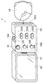
以下、図面を参照して本発明の好ましい実施の形態について詳細に説明する。図1は本発明の一実施の形態によるデジタルビデオカメラの外観図、図2はこのデジタルビデオカメラを構成する主要な要素のブロック図である。
【0014】
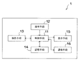
本実施の形態のデジタルビデオカメラ1は、静止画もしくは動画を撮影するためのCCD(撮影手段)13、撮影された静止画もしくは動画のデータを記憶する装脱可能なフレキシブルディスク(記憶手段)14を装填するためのスロット10a、撮影ボタン12aや簡易操作スイッチ群12b等からなる操作手段12、外部機器と通信するための通信手段16と、これらデジタルビデオカメラ1の各部を集中制御するCPU(制御手段)11等が本体部10内に設けられて構成されたものである。
【0015】
本体部10には、モニタ15が連結部材17により回転自在に取り付けられている。また、撮影ボタン12aは本体部10の上面中央に配置されており、CCD13および簡易操作スイッチ群12bは本体部10の前面(主操作面)に配置されている。なお、モニタ15を本体部10に連結する連結部材17の形式は、回転式ではなく、ヒンジ構造を用いて折曲自在、あるいはユニバーサルジョイント構造を用いて3D方向に回転自在としてもよい。
【0016】
上記のように構成することにより、撮影者が、CCD13を手前側もしくは反対側のいずれの方向に向けたときであっても、撮影ボタン12aが本体部10の上面中央に配置されているため、左右で略等しい操作感を得ることができ、また、モニタ15が本体部10に回転自在に取り付けられているため、本体部10の向きに関わらず、モニタ15を撮影者に見やすい方向に向けることができる。なお、モニタ15の表示面が本体部10と直交した時点で、モニタ15に表示する画像の上下を反転させて、モニタ15を回転させても常に表示する画像の上側を本体部10の上側に合わせることにより、撮影者の使用状態に応じて画像を最適に表示させることができる。
【0017】
通信手段16は、携帯電話(もしくはPHS)と同等の機能を有しており、図示しないスピーカーおよびマイクを使用して電話として使用させることも可能であるし、また、パケット通信機能を利用して画像データ等の送受信を行うことも可能である。さらにGPS機能を設けることにより、デジタルビデオカメラ1の現在地、すなわちこのデジタルビデオカメラ1を持つ撮影者の現在地をモニタ15に表示させることも可能である。
【0018】
操作手段12は、撮影ボタン12a、簡易操作スイッチ群12b、および、図示しない携帯電話のプッシュボタンのような多数のボタンを含む詳細操作スイッチ群からなる。
【0019】
詳細操作スイッチ群は、例えば、通信の際の宛先の設定や、撮影した画像のデータの管理等、デジタルビデオカメラ1の操作に必要な種々の機能を備えたボタンにより構成される。この詳細操作スイッチ群は、主操作面以外の場所に配置される。
【0020】
簡易操作スイッチ群12bは、デジタルビデオカメラ1において行われる操作の中で比較的頻度の高い機能の5種のボタンにより構成される。本実施の形態においては、再生スイッチ121、記録スイッチ122、3つの送信先スイッチ123、124、125から構成される。送信先スイッチ123、124、125は、詳細操作スイッチ群により予め設定した3箇所の通信先をボタン毎に呼出し可能にしたものである。このように主操作面に5種類以下のボタンにより構成される簡易操作スイッチ群12bを配置することにより、機械操作に精通しない人に対しても容易に操作をさせることができる。なお、例えば記録スイッチ122を3回断続的に押下することにより消去スイッチとして機能させる等、一つのボタンに複数の機能を備えさせてもよい。
【0021】
記憶手段14には、小径フレキシブルディスクであるclik!(登録商標)を用いる。
【0022】
記憶手段14にclik!(登録商標)のようなフレキシブルディスクを用いることにより、従来用いられていたテープ状メディアと比較した場合に、フレキシブルディスクはランダムアクセス性を備えるため、ユーザが所望するデータに対して高速にアクセスさせることができ、またドライブの駆動部の機構が簡素であるためコストを低く抑えることができ、さらに低消費電力であるためバッテリーの駆動時間を長くすることができる。
【0023】
また、半導体メモリタイプのメディアと比較した場合にも、フレキシブルディスクの価格は半導体メモリタイプのメディアの価格よりも低いため、ユーザに気軽に使用させることができる。
【0024】
上記のように、記憶手段にフレキシブルディスクを用いることにより、従来用いられていたメディアに起因する不具合を解消することができ、デジタルビデオカメラの商品性を向上させることができる。
【0025】
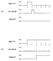
次に、上記構成のデジタルビデオカメラ1の撮影の際の動作について説明する。本実施の形態のデジタルビデオカメラ1は、撮影ボタン12aの押下時間によって動画の撮影と静止画の撮影を切り換える。具体的には、撮影ボタン12aの押下時間が2秒未満の場合は静止画の撮影を行い、撮影ボタン12aの押下時間が2秒以上の場合は動画の撮影を行う。なお、静止画の撮影と動画の撮影を切り換える押下時間の閾値は2秒に限るものではない。図3に撮影ボタンの押下により静止画もしくは動画の記録を行う際のタイミングを示すタイミングチャートを示す。
【0026】
図3(A)に示すように、撮影ボタン12aの押下が2秒未満に解除された場合は、CPU11は、撮影ボタン12aの押下が解除された時点で、CCD13を駆動して静止画の撮影を行い、撮影により得られたデータを記憶手段14に記憶させる。
【0027】
また、図3(B)に示すように、撮影ボタン12aが押下されてから2秒以上経過した場合は、CPU11は、撮影ボタン12aが押下されてから2秒経過した時点で、CCD13を駆動して動画の撮影を開始し、撮影により得られたデータを記憶手段14に記憶させる。なお、動画の記録の停止については、撮影ボタン12aの押下が解除された時点で動画の記録を停止させてもよいし、動画の記録が開始されてから撮影ボタン12aの押下が解除された後に図示しない停止ボタンが押下された時点で動画の記録を停止させてもよい。
【0028】
なお、上記のような態様とした場合、撮影ボタン12aが押下されてから撮影を開始するまでに閾値時間(2秒)のタイムラグを生じるため、以下に示す態様とすることにより、この問題を解消することができる。
【0029】
撮影ボタン12aの押下時間において静止画の記録か動画の記録かを判断する閾値時間以上(本実施の形態では2秒以上)の動画を記憶可能な容量を有するバッファを、CPU11と記憶手段14の間に設け、撮影により得られたデータをこのバッファを介して記憶手段14に記憶させる。
【0030】
CPU11は、撮影ボタン12aが押下された時点からCCD13を駆動して動画の撮影を開始し、撮影により得られたデータをバッファに記憶させる。
【0031】
撮影ボタン12aの押下が2秒未満に解除された場合は、CPU11は、動画の撮影を停止し、バッファに記憶されている一番先頭のフレームのデータを静止画データとして記憶手段14に記憶させる。
【0032】
また、撮影ボタン12aが押下されてから2秒以上経過した場合は、CPU11は、動画の撮影を継続させ、バッファに記憶されている一番先頭のフレームのデータから順に動画データとして記憶手段14に記憶させる。
【0033】
このような態様にすることにより、撮影ボタン12aの押下からデータの記録開始までのタイムラグを無くすことができる。
【0034】
上記のように、1つの撮影ボタン12aにより静止画と動画を選択的に撮影可能とすることにより、撮影の際に静止画の撮影ボタンと動画の撮影ボタン考慮する必要が無くなるため、デジタルビデオカメラ1の使い勝手を向上させることができる。
【図面の簡単な説明】
【図1】本発明の一実施の形態によるデジタルビデオカメラの正面図
【図2】上記デジタルビデオカメラを構成する主要な要素のブロック図
【図3】撮影ボタンの押下により静止画もしくは動画の記録を行う際のタイミングを示すタイミングチャート
【符号の説明】
1 デジタルビデオカメラ
10 本体部
11 制御手段(CPU)
12 操作手段
12a 撮影ボタン
12b 簡易操作スイッチ群
13 撮影手段(CCD)
14 記憶手段
15 表示手段(モニタ)
16 通信手段
17 連結部材[0001]
BACKGROUND OF THE INVENTION
The present invention relates to a digital video camera provided with communication means capable of recording both still images and moving images and capable of transmitting image data taken to an external device.
[0002]
[Prior art]
Currently, digital video cameras capable of recording moving images in digital format instead of the conventional analog format have been commercialized. This digital video camera can record a moving image as a digital signal by the MPEG method, but some of them have a photo shooting function and can record a still image by the JPEG method.
[0003]
Furthermore, some have a communication function, and can transmit moving images and still images taken via a mobile phone or a personal computer, send and receive e-mails, and connect to the Internet to browse homepages.
[0004]
[Problems to be solved by the invention]
Conventionally, in the digital video camera as described above, a tape-shaped medium such as a digital video cassette (DVC) is used as the storage means. However, since the tape-shaped medium does not have random accessibility, There is a disadvantage that it takes time to cue up the moving image stored therein and it is not easy to use. Further, since the mechanism of the drive unit of the drive is complicated, there is a problem that the cost is increased and the power consumption is increased.
[0005]
On the other hand, in order to improve compatibility with personal computers, tape-type media and semiconductor memory type media that can be loaded are also commercialized. However, because semiconductor memory type media is expensive, it was recorded. You can't easily copy data and distribute it to others, or own multiple copies for yourself.
[0006]
The present invention has been made in view of the above problems, and has as its object to eliminate the above-mentioned problems caused by recording media and to improve the merchantability of digital video cameras.
[0007]
[Means for Solving the Problems]
A digital video camera according to the present invention includes a photographing unit capable of selectively photographing still images and moving images, a communication unit that transmits data of an image captured by the photographing unit to at least an external device, and a storage unit that stores data. And a display means for displaying an image, the storage means is a flexible disk that can be attached to and detached from the camera.
[0008]
The flexible disk is, for example, click! (Registered trademark) or the like, preferably 50.8 mm (2 inches) or less in size and large capacity by magnetic recording.
[0009]
【The invention's effect】
Since the digital video camera according to the present invention uses a flexible disk as the storage means, the flexible disk has random accessibility when compared with a tape-like medium, so that data desired by the user can be accessed at high speed. In addition, since the mechanism of the drive unit of the drive is simple, the cost can be kept low, and further, since the power consumption is low, the drive time of the battery can be extended.
[0010]
Also, when compared with semiconductor memory type media, the price of the flexible disk is lower than the price of semiconductor memory type media, so that the user can easily use it.
[0011]
The optical disk has been confirmed to have a record storability of about 20 years, but the magnetic flexible disk has been proven to have a record storability of nearly 100 years. There are two types of recordable optical discs, write-once type and rewritable type. Although write-once type optical discs can be manufactured at a low cost, they are not suitable for use in digital video cameras as in the present application. Since a type optical disk is more expensive than a magnetic type flexible disk, it is preferable to use a magnetic type flexible disk in terms of cost.
[0012]
As described above, by using a flexible disk as the storage means, it is possible to eliminate problems caused by media that have been used conventionally, and to improve the merchantability of digital video cameras.
[0013]
DETAILED DESCRIPTION OF THE INVENTION
Hereinafter, preferred embodiments of the present invention will be described in detail with reference to the drawings. FIG. 1 is an external view of a digital video camera according to an embodiment of the present invention, and FIG. 2 is a block diagram of main elements constituting the digital video camera.
[0014]
The
[0015]
A
[0016]
By configuring as described above, the photographing button 12a is arranged at the center of the upper surface of the
[0017]
The communication means 16 has a function equivalent to that of a cellular phone (or PHS), and can be used as a telephone by using a speaker and a microphone (not shown), and can utilize a packet communication function. It is also possible to send and receive image data and the like. Further, by providing a GPS function, the current location of the
[0018]
The operation means 12 includes a photographing button 12a, a simple
[0019]
The detailed operation switch group includes, for example, buttons having various functions necessary for operation of the
[0020]
The simple
[0021]
The storage means 14 has a click! (Registered trademark) is used.
[0022]
Click on the storage means 14! By using a flexible disk such as (Registered Trademark), the flexible disk has random accessibility when compared with a tape-like medium that has been used in the past, so that data desired by the user can be accessed at high speed. In addition, since the mechanism of the drive unit of the drive is simple, the cost can be kept low. Further, since the power consumption is low, the drive time of the battery can be extended.
[0023]
Also, when compared with semiconductor memory type media, the price of the flexible disk is lower than the price of semiconductor memory type media, so that the user can easily use it.
[0024]
As described above, by using a flexible disk as the storage means, it is possible to eliminate problems caused by media that have been used conventionally, and to improve the merchantability of digital video cameras.
[0025]
Next, an operation at the time of shooting with the
[0026]
As shown in FIG. 3A, when pressing of the shooting button 12a is released in less than 2 seconds, the
[0027]
Also, as shown in FIG. 3B, when two seconds or more have elapsed since the photographing button 12a was pressed, the
[0028]
In the case of the above-described mode, a time lag of a threshold time (2 seconds) is generated from when the shooting button 12a is pressed until shooting starts, so this mode is solved by adopting the mode shown below. can do.
[0029]
A buffer having a capacity capable of storing a moving image that is longer than a threshold time (2 seconds or longer in the present embodiment) for determining whether to record a still image or a moving image when the shooting button 12 a is pressed is stored in the
[0030]
The
[0031]
When the pressing of the shooting button 12a is released in less than 2 seconds, the
[0032]
If two seconds or more have passed after the shooting button 12a is pressed, the
[0033]
By adopting such a mode, it is possible to eliminate a time lag from the pressing of the photographing button 12a to the start of data recording.
[0034]
As described above, since it is possible to selectively shoot still images and moving images with one shooting button 12a, there is no need to consider still image shooting buttons and moving image shooting buttons at the time of shooting. The usability of 1 can be improved.
[Brief description of the drawings]
FIG. 1 is a front view of a digital video camera according to an embodiment of the present invention. FIG. 2 is a block diagram of main elements constituting the digital video camera. FIG. Timing chart showing the timing when performing
DESCRIPTION OF
12 Operating means
14 Storage means 15 Display means (monitor)
16 Communication means 17 Connecting member
Claims (1)
少なくとも外部機器に対して前記撮影手段により撮影した画像のデータを送信する通信手段と、
前記データを記憶する記憶手段と、
前記画像を表示する表示手段とを備えてなるデジタルビデオカメラにおいて、前記記憶手段が、カメラに装脱可能なフレキシブルディスクであることを特徴とするデジタルビデオカメラ。Photographing means capable of selectively photographing still images and moving images;
Communication means for transmitting data of an image photographed by the photographing means to at least an external device;
Storage means for storing the data;
A digital video camera comprising display means for displaying the image, wherein the storage means is a flexible disk that can be attached to and detached from the camera.
Priority Applications (2)
| Application Number | Priority Date | Filing Date | Title |
|---|---|---|---|
| JP2002198785A JP2004040725A (en) | 2002-07-08 | 2002-07-08 | Digital video camera |
| US10/614,044 US20040027467A1 (en) | 2002-07-08 | 2003-07-08 | Digital video camera |
Applications Claiming Priority (1)
| Application Number | Priority Date | Filing Date | Title |
|---|---|---|---|
| JP2002198785A JP2004040725A (en) | 2002-07-08 | 2002-07-08 | Digital video camera |
Publications (1)
| Publication Number | Publication Date |
|---|---|
| JP2004040725A true JP2004040725A (en) | 2004-02-05 |
Family
ID=31492025
Family Applications (1)
| Application Number | Title | Priority Date | Filing Date |
|---|---|---|---|
| JP2002198785A Withdrawn JP2004040725A (en) | 2002-07-08 | 2002-07-08 | Digital video camera |
Country Status (2)
| Country | Link |
|---|---|
| US (1) | US20040027467A1 (en) |
| JP (1) | JP2004040725A (en) |
Families Citing this family (12)
| Publication number | Priority date | Publication date | Assignee | Title |
|---|---|---|---|---|
| US6295088B1 (en) * | 1997-02-17 | 2001-09-25 | Nikon Corporation | Portable display device |
| US7339615B2 (en) * | 1999-12-22 | 2008-03-04 | Fujifilm Corporation | Method and apparatus for capturing images and for recording data that includes image data and audio data separately prepared from the image data |
| US20050093988A1 (en) * | 2003-11-03 | 2005-05-05 | Haas William R. | Digital camera with automatic mode detection |
| ES2367044T3 (en) * | 2005-08-24 | 2011-10-27 | Koninklijke Philips Electronics N.V. | LIGHTING MODULE |
| TW201112745A (en) * | 2009-09-29 | 2011-04-01 | Asia Optical Co Inc | Anti-shake image capturing device and Method |
| KR101720776B1 (en) * | 2010-12-27 | 2017-03-28 | 삼성전자주식회사 | Digital image photographing apparatus and method for controlling the same |
| CN102722321A (en) * | 2012-05-22 | 2012-10-10 | 中兴通讯股份有限公司 | Method and device for switching between double cameras |
| JP5892134B2 (en) * | 2013-09-20 | 2016-03-23 | カシオ計算機株式会社 | Imaging apparatus, imaging method, and program |
| US9258480B2 (en) * | 2014-03-31 | 2016-02-09 | Facebook, Inc. | Techniques to selectively capture visual media using a single interface element |
| US10708488B2 (en) | 2016-09-27 | 2020-07-07 | Snap Inc. | Eyewear device mode indication |
| US11470244B1 (en) * | 2017-07-31 | 2022-10-11 | Snap Inc. | Photo capture indication in eyewear devices |
| US11006043B1 (en) * | 2018-04-03 | 2021-05-11 | Snap Inc. | Image-capture control |
Family Cites Families (10)
| Publication number | Priority date | Publication date | Assignee | Title |
|---|---|---|---|---|
| US5838458A (en) * | 1992-02-25 | 1998-11-17 | Tsai; Irving | Method and apparatus for linking designated portions of a received document image with an electronic address |
| JPH08140026A (en) * | 1994-11-04 | 1996-05-31 | Canon Inc | Compound camera |
| JPH0922581A (en) * | 1995-07-03 | 1997-01-21 | Sony Corp | VTR integrated camera device |
| US6750902B1 (en) * | 1996-02-13 | 2004-06-15 | Fotonation Holdings Llc | Camera network communication device |
| JPH1079910A (en) * | 1996-09-05 | 1998-03-24 | Sony Corp | VTR integrated camera device |
| US6005613A (en) * | 1996-09-12 | 1999-12-21 | Eastman Kodak Company | Multi-mode digital camera with computer interface using data packets combining image and mode data |
| US6295088B1 (en) * | 1997-02-17 | 2001-09-25 | Nikon Corporation | Portable display device |
| JP4123327B2 (en) * | 2000-11-28 | 2008-07-23 | 富士フイルム株式会社 | Camera with audio playback function |
| JP2002182285A (en) * | 2000-12-11 | 2002-06-26 | Fuji Photo Optical Co Ltd | Camera |
| US7092735B2 (en) * | 2002-03-22 | 2006-08-15 | Osann Jr Robert | Video-voicemail solution for wireless communication devices |
-
2002
- 2002-07-08 JP JP2002198785A patent/JP2004040725A/en not_active Withdrawn
-
2003
- 2003-07-08 US US10/614,044 patent/US20040027467A1/en not_active Abandoned
Also Published As
| Publication number | Publication date |
|---|---|
| US20040027467A1 (en) | 2004-02-12 |
Similar Documents
| Publication | Publication Date | Title |
|---|---|---|
| US7209648B2 (en) | Multimedia recording system and method | |
| JP2005260959A (en) | Imaging device | |
| JPH11289484A (en) | Camera with monitor | |
| JP2003008946A (en) | Imaging device | |
| JP2004040725A (en) | Digital video camera | |
| JP2002314916A (en) | Video camera, video camera recording / reproducing method and program | |
| JP2000023012A5 (en) | ||
| TWI260526B (en) | Imaging device | |
| JP4407137B2 (en) | Portable electronic device, operation control method and program for portable electronic device | |
| JPH1164928A (en) | Camera with digital memory | |
| JP2005086476A (en) | Display device | |
| JP2004282605A (en) | Portable electronic device system, portable electronic device, charge control method and program for portable electronic device | |
| JP4150090B2 (en) | Video recording device | |
| JP2000352759A (en) | Electronic camera | |
| JP3829645B2 (en) | Digital camera | |
| JP4003793B2 (en) | Video recording device | |
| JP4211429B2 (en) | Imaging device | |
| JP2002109528A (en) | Data storage device | |
| JP2000165719A (en) | Image pickup device | |
| JP4186618B2 (en) | Imaging device | |
| JP4184166B2 (en) | Audio recording / playback device | |
| CN100380925C (en) | Video camera | |
| JPH02226970A (en) | Electronic image pickup device | |
| JP3248481B2 (en) | Electronic camera | |
| JP2004194102A (en) | Digital camera |
Legal Events
| Date | Code | Title | Description |
|---|---|---|---|
| A621 | Written request for application examination |
Free format text: JAPANESE INTERMEDIATE CODE: A621 Effective date: 20050208 |
|
| A711 | Notification of change in applicant |
Free format text: JAPANESE INTERMEDIATE CODE: A712 Effective date: 20061205 |
|
| A131 | Notification of reasons for refusal |
Free format text: JAPANESE INTERMEDIATE CODE: A131 Effective date: 20070313 |
|
| A761 | Written withdrawal of application |
Free format text: JAPANESE INTERMEDIATE CODE: A761 Effective date: 20070514 |