JP2004040719A - Node device, communication module mounting unit, mounting method of a plurality of subsystems, and information transmission system - Google Patents
Node device, communication module mounting unit, mounting method of a plurality of subsystems, and information transmission system Download PDFInfo
- Publication number
- JP2004040719A JP2004040719A JP2002198749A JP2002198749A JP2004040719A JP 2004040719 A JP2004040719 A JP 2004040719A JP 2002198749 A JP2002198749 A JP 2002198749A JP 2002198749 A JP2002198749 A JP 2002198749A JP 2004040719 A JP2004040719 A JP 2004040719A
- Authority
- JP
- Japan
- Prior art keywords
- communication module
- module
- active
- working
- standby
- Prior art date
- Legal status (The legal status is an assumption and is not a legal conclusion. Google has not performed a legal analysis and makes no representation as to the accuracy of the status listed.)
- Pending
Links
Images
Landscapes
- Time-Division Multiplex Systems (AREA)
- Data Exchanges In Wide-Area Networks (AREA)
Abstract
【課題】各サブシステムの備える機能を犠牲にすること無くインタフェース基板の高密度化を図ったノード装置、通信モジュール実装ユニット、複数のサブシステムの実装方法および情報伝送システムを提供する。
【解決手段】現用系の送受信モジュール10,12,20,22と、この現用系モジュールに障害が生じた場合にその切り替え先となる予備系送受信モジュール11,13,21,23とを、同じ基板に実装することを避けるようにする。すなわち、現用系の送受信モジュールに切り替え要因が生じた場合に切り替え先となる予備系送受信モジュールが必ず他の基板上に有るような実装形態をとる。これにより送受信モジュールの冗長性を確保し、冗長切り替えに係わる機能低下を引き起こさずに基板の高密度実装を可能とする。
【選択図】 図5Provided are a node device, a communication module mounting unit, a mounting method of a plurality of subsystems, and an information transmission system in which the density of an interface board is increased without sacrificing the functions of each subsystem.
An active transmission / reception module (10, 12, 20, 22) and a standby transmission / reception module (11, 13, 21, 23) to be switched to when a failure occurs in the active module are provided on the same board. Avoid implementing it in That is, when a switching factor occurs in the active transmission / reception module, a mounting mode is adopted in which the standby transmission / reception module to be switched to is always on another board. As a result, the redundancy of the transmission / reception module is ensured, and high-density mounting of the board is enabled without causing a reduction in the function related to the redundancy switching.
[Selection diagram] FIG.
Description
【0001】
【発明の属する技術分野】
本発明は、例えばSDH(Synchronous Digital Hierarchy)/SONET(Synchronous Optical Network)に準拠するネットワークで使用されるノード装置、通信モジュール実装ユニット、複数のサブシステムの実装方法および情報伝送システムに関する。
【0002】
【従来の技術】
近年の情報通信システムにおける帯域需要は増加の一途を辿っており、光通信技術を応用して伝送容量の拡大を図ることが盛んに行われている。光通信技術のなかでも、WDM(Wavelength Division Multiplexing)を応用した波長多重光伝送システムが注目されている。
【0003】
この種のシステムでは、複数のノード装置を単波長光回線を介して接続したネットワークを一つのサブシステムとし、複数のサブシステムをWDM技術により多重化することで伝送容量の拡大が図られている。しかしながらこのような構成ではノード装置の数が多くなり易く、ノード装置が設置される局舎のフロアスペースの増大や、消費電力の増加などの不具合を生じることが分かってきている。
【0004】
一方、ノードに実装され通信回線を収容するインタフェース基板(以下、基板と称する)を高密度化し、省サイズ化を図ることが近年の半導体集積技術の進歩により可能となってきている。そこで、基板自体を省サイズ化することよりも、むしろ、一つの基板に複数のサブシステムの通信回線を収容することにより全体的な省サイズ化を図る試みがなされようとしている。すなわち、複数のサブシステムを収容するに足る機能を一つのノード装置に持たせることにより、上記したような不具合を解決しようという試みが有る。
【0005】
ところで、上記サブシステムには、耐障害性能への配慮から、例えばSDH/SONETに代表されるようなセルフヒーリング(Self Healing)機能を備えるアーキテクチャが適用されることが多い。この種のアーキテクチャに準拠するシステムは、サービス系とプロテクション系とを有する。そして、障害の発生時にはサービスラインを流れるサービストラフィックがプロテクションラインに迂回させられ、これによりサービストラフィックが救済される。
【0006】
【発明が解決しようとする課題】
上記したように、一つの基板に複数のサブシステムを実装することにより情報通信システムのトータルでの省サイズ化を図ろうとする試みが有る。しかしながら、同じ基板に同じサブシステムの構成要素を集めて実装すると、基板冗長の保証を取ることができなくなる。このことは、セルフヒーリング機能のような、各サブシステムが備える機能が損なわれてしまうことを意味する。すなわち、各サブシステムの備える機能を犠牲にすること無く基板を高密度化するには、サブシステムの基板への実装の形態に工夫を要する。
【0007】
本発明は上記事情によりなされたもので、その目的は、各サブシステムの備える機能を犠牲にすること無くインタフェース基板の高密度化を図ったノード装置、通信モジュール実装ユニット、複数のサブシステムの実装方法および情報伝送システムを提供することにある。
【0008】
【課題を解決するための手段】
上記目的を達成するために本発明に係わるノード装置は、複数のノード装置と、これらのノード装置を接続する現用系および予備系伝送路と、前記ノード装置と前記現用系および予備系伝送路とに論理的に多重される複数のサブシステムとを具備し、前記複数のサブシステムのそれぞれは、前記現用系伝送路を介して伝送される自システムに係わるサービストラフィックを前記予備系伝送路を用いて障害から救済するトラフィック救済手段を備える情報伝送システムに備えられる前記ノード装置であって、前記サブシステムごとに設けられ、前記現用系伝送路に接続される複数の現用系通信モジュールと、前記サブシステムごとに当該サブシステムの現用系通信モジュールに対応付けて設けられ、前記予備系伝送路に接続され、対応する現用系通信モジュールに障害が発生した場合には前記トラフィック救済手段により当該現用系通信モジュールの代替として切り替えられる複数の予備系通信モジュールとを備える場合に、障害の発生に備えて交換可能に設けられ、前記複数の現用系通信モジュールおよび前記複数の予備系通信モジュールからなる群から複数の通信モジュールを一定の組み合わせ条件のもとで選択して形成される複数のモジュール群を、それぞれ個別に実装してなる複数のモジュール実装部を備え、前記組み合わせ条件は、前記現用系通信モジュールとこの現用系通信モジュールと同じサブシステムに属して当該現用系通信モジュールの切り替え相手先となる予備系通信モジュールとが同じモジュール群に含まれることを避けるという条件であることを特徴とする。
【0009】
このような手段を講じることにより、ある現用系通信モジュールと、この現用系通信モジュールに係わる障害が発生した際にその切り替え相手先となる予備系通信モジュールとは、必ず別のモジュール実装部に実装されることになる。これにより、例えばモジュール実装部を基板として形成した場合、この基板自体に障害が発生した場合の冗長を保証することが可能となる。従って、システムが備えているトラフィック救済機能を犠牲にすること無く、基板の高密度化を図ることが可能となる。
【0010】
【発明の実施の形態】
以下、図面を参照して本発明の実施の形態を詳細に説明する。この実施形態では、世界標準としてのSDH(Synchronous Digital Hierarchy )に即したシステムを想定する。
【0011】
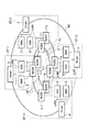
図1は、本発明の実施の形態に係わる情報伝送システムの論理的構造を示すシステム図である。図1において、例えば海洋を隔てて設置される複数の局舎(Station)ST−1〜ST−mのそれぞれに、複数のノード装置(NODE)1−1〜1−nが設置される。ノード装置1−1〜1−nは、図1においては論理的なエンティティとして存在するもので、以下、論理ノードと称する。
【0012】
論理ノード1−1〜1−nは局舎間を跨る高速回線OFによりリング状に接続され、複数の論理ノード1−1間、論理ノード1−2間,…,論理ノード1−n間でリングネットワークが形成される。各リングネットワークは、それぞれ図1のシステムのサブシステムである。すなわちn個のサブシステムが存在し、各サブシステムはそれぞれm個の論理ノード1−1,1−2,…,1−nから形成される。それぞれのサブシステムは、APS(Automatic Protection Switching)と称されるセルフヒーリング機能を備える。
【0013】
論理ノード1−1間,1−2間,…,および1−n間を結ぶ高速回線OFは、各サブシステムに割り当てられた波長の光信号を伝送する。すなわち伝送波長はサブシステムごとに互いに異なり、これらの波長が多重されて波長多重回線FLが形成される。高速回線OFのインタフェースには、SDHに準拠する例えばSTM−64(Synchronous Transfer Module−level 64:10Gbpsに相当)などが採用される。
【0014】
局舎ST−1〜ST−mにおける論理ノード1−1〜1−nは、各局舎内においてそれぞれ局舎内監視制御装置(SSE)2に接続される。SSE2は、網内全域に渡る監視制御を担う監視制御装置(NME)3に、LAN(Local area Network)を介して接続される。LANにはルータ(Router)4が接続され、ルータ4を介して各局舎のNME3同士を結ぶ管理ネットワークMLが形成される。管理ネットワークMLは、論理的には波長多重回線FLを介して伝送されるSDHフレームのSOH(Section Over Head )におけるDCC(Data Communication Channel)などとして実現される。
【0015】
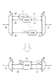
図2に示されるように、論理ノード1−1〜1−nは、共通の筐体を有する実態としてのノード装置(以下ノードと称する)N1に実装される。他の論理ノードも同様に、共通の筐体を有する装置に実装される。図2において、波長多重回線FLを流れる波長多重光は波長多重分離部50において個々の波長光に分離され、高速回線OFを介してノードN1に導入される。ノードN1において、各論理ノード1−1〜1−nによりそれぞれの波長光に対する処理がなされる。なお、高速回線OFはサービスラインSLとプロテクションラインPLとを備えて二重化される。
【0016】
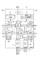
図3は、図2のノードN1における1つのサブシステムに係わる部分の構成を示す図である。図2において、サービスラインSLは、East側において送受信モジュール10に、West側において送受信モジュール12に接続される。プロテクションラインPLは、East側において送受信モジュール11に、West側において送受信モジュール13に接続される。すなわち、送受信モジュール10,12は現用系、送受信モジュール11,14に属する。各送受信モジュール10〜13は、図示しない基板に実装される。
【0017】
送受信モジュール10〜13を介して装置内部に導入されるSTM−64信号は、タイムスロット交換部(TSA:Time Slot Assignment)201と、タイムスロット交換部202とに与えられる。タイムスロット交換部201,202は、STM−64信号に時分割多重されたタイムスロットのうち所定のタイムスロットをドロップする。このドロップされたスロットは、トリビュタリインタフェース(LS I/F)シェルフ31〜3kを介して、低次群信号としてトリビュタリ伝送路LLから送出される。
【0018】
これに対し、トリビュタリ伝送路LLからLS I/Fシェルフ31〜3kを介して装置内部に導入される低次群信号は、タイムスロット交換部201,202に与えられ、STM−64フレームの所定のタイムスロットにアッドされて、高速回線OFを介して他のノードに向け送出される。
【0019】
タイムスロット交換部201と、タイムスロット交換部202とは、対を成して二重化されている。タイムスロット交換部201は、システムの定常時における現用系として動作される。このタイムスロット交換部201に障害が生じた場合には、タイムスロット交換部202がタイムスロット交換部201の代わりに動作される。このようにして、装置内冗長が実現される。
【0020】
なお、システム正常時には、タイムスロット交換部202はパートタイムトラフィック(P/T)の伝送に係わるように動作される。パートタイムトラフィックとは、サービスラインSLを流れるサービストラフィックとは異なる情報を載せた信号である。システム正常時には、無障害のためプロテクションラインPLが空きとなる。パートタイムトラフィックはこの帯域を利用して伝送されるトラフィックであり、サービストラフィックよりも優先度の低いトラフィックとして取り扱われる。
【0021】
また本実施形態においては、プロテクションラインPLにパートタイムトラフィックを収容するため、予備系の送受信モジュール11,13にパートタイムトラフィックインタフェース部(P/Tインタフェース部)100を備える。P/Tインタフェース部100は、サービスラインSLおよび現用系送受信モジュール10,12を介してサービストラフィックが伝送されている状態において、パートタイムトラフィックをプロテクションラインPLに収容する。
【0022】
このほか、図3のノードN1は、制御部5と、各種の制御プログラムなどを記憶する記憶部6と、SSE2とのインタフェースをとる管理網インタフェース(I/F)7とを備える。
【0023】
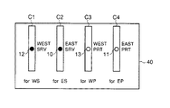
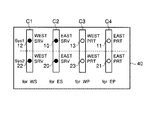
図4は、既存のシステムにおいて送受信モジュールがノードに実装される状態を示す図である。図4において、符号C1〜C4はそれぞれインタフェース基板を示す。各基板C1〜C4は、シェルフ40に挿抜可能に設けられる。符号10は現用系EAST側(EAST SRV)に設けられる送受信モジュールを示す。符号11は予備系EAST側(EAST PRT)に設けられる送受信モジュールを示す。符号12は現用系WEST側(WEST SRV)に設けられる送受信モジュールを示す。符号13は予備系WEST側(WEST PRT)に設けられる送受信モジュールを示す。
【0024】
図4において、送受信モジュール12は基板C1に実装される。送受信モジュール10は基板C2に実装される。送受信モジュール13は基板C3に実装される。送受信モジュール11は基板C4に実装される。このように既存のシステムでは、一つの基板に対し一つの送受信モジュールが実装される。
【0025】
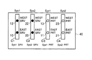
図5は、本実施形態において送受信モジュールがノードに実装される状態の一例を示す図である。本実施形態においては、一つの基板に複数の送受信モジュールを実装する。図5においては、Sys1、またはSys2として区別される2つのサブシステムにそれぞれ4つ備わる送受信モジュールを、4枚の基板C1〜C4に実装する場合を想定する。送受信モジュール10〜13はサブシステムSys1に、送受信モジュール20〜23はサブシステムSys2にそれぞれ属する。
【0026】
図5において、符号20はサブシステムSys2において現用系EAST側(EAST SRV)に設けられる送受信モジュールを示す。符号21は予備系EAST側(EAST PRT)に設けられる送受信モジュールを示す。符号22は現用系WEST側(WEST SRV)に設けられる送受信モジュールを示す。符号23は予備系WEST側(WEST PRT)に設けられる送受信モジュールを示す。
【0027】
図5において、基板C1に、送受信モジュール12と送受信モジュール22とが実装される。基板C2に、送受信モジュール10と送受信モジュール20とが実装される。基板C3に、送受信モジュール13と送受信モジュール23とが実装される。基板C4に、送受信モジュール11と送受信モジュール21とが実装される。
【0028】
このように図5においては、複数のサブシステムの送受信モジュールが、それぞれ現用系同士、あるいは予備系同士にそれぞれまとめられて同じ基板に実装される。すなわち、基板C1〜C4は複数の送受信モジュールを実装するが、それぞれ現用系送受信モジュール、または予備系送受信モジュールのうちいずれか一方のみを含む。しかも、基板C1〜C4に実装される送受信モジュールは、いずれも異なるサブシステムに属する。
【0029】
このようにしたので、現用系の送受信モジュール10,12,20,または,22の切り替え先となる予備系の送受信モジュールは、必ず他の基板上に有る。従っていずれかの基板に障害が発生した場合でも、送受信モジュールを現用系から予備系へと切り替える冗長切替処理を、支障なく実施することができる。例えば基板C1に障害が生じた場合、送受信モジュール12は基板C3の送受信モジュール13に、送受信モジュール22は基板C3の送受信モジュール23に、それぞれ切り替えられる。基板C2についても同様に、基板C4が切り替え先となる。このように図5の実装形態によれば、基板に障害が発生した場合でも冗長切替処理に係わる機能の低下を引き起こさずに、複数の送受信モジュールを、同じ基板に実装することが可能となる。これにより、各サブシステムの備える機能を犠牲にすること無く、基板上に複数の送受信モジュールを高密度実装することが可能になる。
【0030】
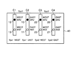
図6は、本実施形態において送受信モジュールがノードに実装される状態の他の例を示す図である。図6においても、サブシステムSys1、Sys2にそれぞれ4つ備わる送受信モジュールを、基板C1〜C4に実装する場合を想定する。
【0031】
図6において、基板C1に、送受信モジュール12と送受信モジュール10とが実装される。基板C2に、送受信モジュール22と送受信モジュール20とが実装される。基板C3に、送受信モジュール13と送受信モジュール11とが実装される。基板C4に、送受信モジュール23と送受信モジュール21とが実装される。
【0032】
このように図6においては、複数のサブシステムの送受信モジュールが、それぞれ現用系同士、あるいは予備系同士にそれぞれまとめられて同じ基板に実装される。すなわち、基板C1〜C4は複数の送受信モジュールを実装するが、それぞれ現用系送受信モジュール、または予備系送受信モジュールのうちいずれか一方のみを含む。但し図6においては、同じ基板に、同じサブシステムに属する送受信モジュールが実装される。すなわち基板C1とC3とは、サブシステムSys1用としての位置付けになる。また基板C2とC4とは、サブシステムSys2用としての位置付けになる。
【0033】
このような実装形態によっても、現用系の送受信モジュール10,12,20,または,22の切り替え先となる予備系の送受信モジュールは、必ず他の基板上に有る。従って図6の実装形態によっても、図5の実装形態と同様に、各サブシステムの備える機能を犠牲にすること無く、基板上に複数の送受信モジュールを高密度実装することが可能になる。
【0034】
以上をまとめると、本実施形態における送受信モジュールの基板への実装方法は、要するに次のごとくである。すなわち本実施形態においては、現用系の送受信モジュールと、この現用系モジュールに障害が生じた場合にその切り替え先となる予備系送受信モジュールとを、同じ基板に実装することを避けるようにする。このようにすることで、現用系の送受信モジュールに切り替え要因が生じた場合には、切り替え先の予備系送受信モジュールは、必ず他の基板上に有る。これにより送受信モジュールの冗長性が確保され、冗長切り替えに係わる機能低下を引き起こさずに、基板の高密度実装が可能となる。
【0035】
なお、図5、図6に示されるいずれの実装形態においても、基板障害だけでなく、送受信モジュールに接続されるサービスラインSLに障害が発生した場合の冗長性をも確保できることは、自明である。
【0036】
図7は、本実施形態においてシステム的に禁止される送受信モジュールの実装の状態を示す図である。図7において、基板C1に、送受信モジュール12と送受信モジュール13とが実装される。基板C2に、送受信モジュール10と送受信モジュール11とが実装される。基板C3に、送受信モジュール22と送受信モジュール23とが実装される。基板C4に、送受信モジュール20と送受信モジュール21とが実装される。
【0037】
このような実装形態では、現用系の送受信モジュール10,12,20,22の切り替え先の予備系送受信モジュールが、いずれも同じ基板に実装されることになる。このため、伝送路障害に対する冗長性は確保できるものの、基板に障害が生じた際の冗長切り替えをサポートすることができなくなる。したがって本実施形態では、図7に示されるような実装形態をシステム的に禁止するようにする。
【0038】
なお、図5〜図7において、基板がシェルフ上に配列される順序は意味を持たない。すなわち、基板をシェルフ上に、どのように配列しても良い。本実施形態においては、同じ基板に、どのような組み合わせで送受信モジュールを実装するかということだけが意味を持つ。
【0039】
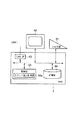
図8を参照して、次に、本実施形態に係わる監視制御装置3の構成につき説明する。図8は、図1に示されるNME3の構成を示すブロック図である。NME3は、ヒューマンマシンインタフェースとしての入出力部61と、表示部62と、LANを介してSSE2およびルータ4との接続インタフェースをとるインタフェース部(LAN I/F)63と、各種動作プログラムなどを記憶する記憶部64と、制御部65とを備える。
【0040】
制御部65は、コマンド投入制御部65aを備える。コマンド投入制御部65aは、図5または図6に示される基板C1〜C4のうち少なくとも一つを任意に指定して、指定された基板に実装される現用系または予備系送受信モジュールに対して一括して同様の指示を与える外部コマンド生成し、この外部コマンドを対象とするノード装置に送信する。
【0041】
一方、図2において、ノード装置N1の制御部5は、コマンド受信制御部5aを備える。コマンド受信制御部5aは、コマンド投入制御部65aから送信された外部コマンドを受信する。そして、この外部コマンドが対象とする基板に実装される現用系または予備系通信モジュールに対してこの外部コマンドに記述される指示を与える。
【0042】
なお、コマンド投入制御部65a、およびコマンド受信制御部5aのいずれも、例えばCPU(Central Processing Unit)のソフトウェア処理を中核として他のハードウェアとの協調動作により実現される機能オブジェクトである。
【0043】
このような構成をとることにより、ノード装置N1の基板に実装される全ての送受信モジュールをターゲットとする一括コマンドを、ノード装置N1に投入するという機能を監視制御装置3の1機能としてサポートすることができるようになる。この機能は、例えば監視制御装置3の表示部62に表示される専用のクリッカブルボタンをクリックすることなどにより、呼び出される。
【0044】
例えば、SDHには、Forced Switchと称される強制的な切り替え機能が備えられている。図5のSys1のWEST SRV送受信モジュール12と、Sys2のWEST SRV送受信モジュール22との両方にForced Switchコマンドを投入する場合には、“WEST SRVの送受信モジュールに、にForced Switchを投入”という形態のオペレーションにより、一度の作業で済ませることが可能になる。これにより、一つの基板に実装される複数の送受信モジュールに対して何度も同じコマンドを投入しなければならないという煩わしさを解消することが可能になる。これは、基板のメンテナンスオペレーションを実施する場合などに有効である。このほか、冗長切り替え機能を一時的に停止するLockout of protectionなどのコマンドも同様に、一括投入のかたちでノード装置に与えることができる。
【0045】
以上述べたように本実施形態では、現用系の送受信モジュール10,12,20,22と、この現用系モジュールに障害が生じた場合にその切り替え先となる予備系送受信モジュール11,13,21,23とを、同じ基板に実装することを避けるようにする。これにより送受信モジュールの冗長性が確保され、冗長切り替えに係わる機能低下を引き起こさずに基板の高密度実装を実現することが可能となる。
【0046】
なお、本発明は上記実施の形態に限定されるものではない。例えば本実施形態では、多重信号を伝送する高速回線OF側に設けられる基板への送受信モジュールの実装形態につき説明した。本発明にかかる技術思想は、トリビュタリ伝送路LLに接続されるLS I/Fシェルフ31〜3kに設けられる基板に対しても、同様に適用できる。
【0047】
また本実施形態では、2つのサブシステムを実装する場合を開示したが、更に多くのサブシステムを実装することも可能である。すなわち本発明にかかる技術思想は、任意の数のサブシステム分に亘る送受信モジュールを共通の基板に実装する場合に、一般に適用することができる。
【0048】
また、現用系の送受信モジュールと、この現用系モジュールに障害が生じた場合にその切り替え先となる予備系送受信モジュールとを、同じ基板に実装することを避けるという条件さえ満たせば、図示した以外の実装形態も可能である。例えば、図7において、予備系送受信モジュール11と13とを入れ換え、また予備系送受信モジュール21と23とを入れ換えるようにすれば、上記の条件を満たすことができる。このほかにも、種々の実装形態がある。
このほか、本発明の要旨を逸脱しない範囲で種々の変形実施を行うことができる。
【0049】
【発明の効果】
以上詳述したように本発明によれば、各サブシステムの備える機能を犠牲にすること無くインタフェース基板の高密度化を図ったノード装置、通信モジュール実装ユニット、複数のサブシステムの実装方法および情報伝送システムを提供することができる。
【図面の簡単な説明】
【図1】本発明の実施の形態に係わる情報伝送システムの論理的構造を示すシステム図。
【図2】図1に示される論理ノード1−1〜1−nと、ノードN1との関係を示す図。
【図3】図2のノードN1における1つのサブシステムに係わる部分の構成を示す図。
【図4】既存のシステムにおいて送受信モジュールがノードに実装される状態を示す図。
【図5】本発明の実施の形態において送受信モジュールがノードに実装される状態の一例を示す図。
【図6】本発明の実施の形態において送受信モジュールがノードに実装される状態の他の例を示す図。
【図7】本発明の実施の形態においてシステム的に禁止される送受信モジュールの実装の状態を示す図。
【図8】図1に示されるNME3の構成を示すブロック図。
【符号の説明】
ST…局舎
OF…高速回線
FL…波長多重回線
ML…管理ネットワーク
N1…ノード装置(Node)
SL…サービスライン
PL…プロテクションライン
LL…トリビュタリ伝送路
C1〜C4…基板
Sys1,Sys2…サブシステム
1…ノード装置
1−1〜1−n…論理ノード
2…局舎内監視制御装置(SSE)
3…監視制御装置(NME)
4…ルータ
5…制御部
5a…コマンド受信制御部
6…記憶部
7…管理網インタフェース
10、12…現用系送受信モジュール
11、13…予備系送受信モジュール
31〜3k…トリビュタリインタフェースシェルフ
40…シェルフ
50…波長多重分離部
61…入出力部
62…表示部
63…インタフェース部
64…記憶部
65…制御部
65a…コマンド投入制御部
100…パートタイムトラフィックインタフェース部
201,202…タイムスロット交換部[0001]
TECHNICAL FIELD OF THE INVENTION
The present invention relates to a node device, a communication module mounting unit, a plurality of subsystem mounting methods, and an information transmission system used in a network conforming to, for example, SDH (Synchronous Digital Hierarchy) / SONET (Synchronous Optical Network).
[0002]
[Prior art]
2. Description of the Related Art In recent years, the demand for bandwidth in information communication systems has been steadily increasing, and it has been actively pursued to expand transmission capacity by applying optical communication technology. Among optical communication technologies, a wavelength division multiplexing optical transmission system to which WDM (Wavelength Division Multiplexing) is applied has attracted attention.
[0003]
In this type of system, a network in which a plurality of node devices are connected via a single-wavelength optical line is regarded as one subsystem, and the transmission capacity is expanded by multiplexing the plurality of subsystems using WDM technology. . However, it has been found that such a configuration tends to increase the number of node devices and causes problems such as an increase in floor space of a station where the node devices are installed and an increase in power consumption.
[0004]
On the other hand, recent advances in semiconductor integrated technology have made it possible to increase the density of interface boards (hereinafter, referred to as boards) that are mounted on nodes and accommodate communication lines, and to reduce the size. Therefore, rather than reducing the size of the substrate itself, attempts are being made to reduce the overall size by accommodating the communication lines of a plurality of subsystems on one substrate. In other words, there is an attempt to solve the above-described problem by providing one node device with a function sufficient to accommodate a plurality of subsystems.
[0005]
By the way, an architecture having a self-healing (Self Healing) function typified by, for example, SDH / SONET is often applied to the above-described subsystem from the viewpoint of fault tolerance performance. Systems conforming to this type of architecture have a service system and a protection system. When a failure occurs, the service traffic flowing through the service line is diverted to the protection line, thereby relieving the service traffic.
[0006]
[Problems to be solved by the invention]
As described above, there are attempts to reduce the total size of an information communication system by mounting a plurality of subsystems on one board. However, if the components of the same subsystem are collectively mounted on the same board, the redundancy of the board cannot be guaranteed. This means that functions provided in each subsystem, such as a self-healing function, are impaired. That is, in order to increase the density of the board without sacrificing the functions of each subsystem, it is necessary to devise a form of mounting the subsystem on the board.
[0007]
SUMMARY OF THE INVENTION The present invention has been made in view of the above circumstances, and has as its object to implement a node device, a communication module mounting unit, and a plurality of sub-systems, which achieve a high-density interface board without sacrificing the functions of each sub-system. A method and an information transmission system are provided.
[0008]
[Means for Solving the Problems]
In order to achieve the above object, a node device according to the present invention includes a plurality of node devices, an active system and a protection system transmission line connecting these node devices, the node device and the working system and the protection system transmission line. A plurality of subsystems that are logically multiplexed with each other, wherein each of the plurality of subsystems uses the protection transmission line to transmit service traffic related to the own system transmitted through the working transmission line. The node device provided in an information transmission system including a traffic rescue means for relieving a failure by providing a plurality of active communication modules provided for each of the subsystems and connected to the active transmission line; Each system is provided in association with the working communication module of the subsystem, connected to the protection transmission line, and In the case where a failure occurs in the communication module, when a plurality of backup communication modules are switched by the traffic rescue means as a substitute for the working communication module, the communication module is provided so as to be exchangeable in preparation for the occurrence of the failure, A plurality of module groups formed by selecting a plurality of communication modules from a group consisting of a plurality of active communication modules and the plurality of standby communication modules under certain combination conditions are individually mounted. A plurality of module mounting units, wherein the combination condition is such that the active communication module and the standby communication module to which the active communication module is to be switched to belong to the same subsystem as the active communication module. It is characterized by the condition of avoiding being included in a group
[0009]
By taking such measures, a certain active communication module and a standby communication module to be switched to when a failure related to the active communication module occurs are always mounted in separate module mounting parts. Will be done. Thus, for example, when the module mounting portion is formed as a substrate, it is possible to guarantee redundancy when a failure occurs in the substrate itself. Therefore, it is possible to increase the density of the substrate without sacrificing the traffic rescue function provided in the system.
[0010]
BEST MODE FOR CARRYING OUT THE INVENTION
Hereinafter, embodiments of the present invention will be described in detail with reference to the drawings. In this embodiment, a system conforming to SDH (Synchronous Digital Hierarchy) as a global standard is assumed.
[0011]
FIG. 1 is a system diagram showing a logical structure of an information transmission system according to an embodiment of the present invention. In FIG. 1, for example, a plurality of node devices (NODEs) 1-1 to 1-n are installed in a plurality of stations (Stations) ST-1 to ST-m installed across the ocean, for example. The node devices 1-1 to 1-n exist as logical entities in FIG. 1 and are hereinafter referred to as logical nodes.
[0012]
The logical nodes 1-1 to 1-n are connected in a ring by a high-speed line OF extending between stations, and are connected between a plurality of logical nodes 1-1, between logical nodes 1-2, ..., and between logical nodes 1-n. A ring network is formed. Each ring network is a subsystem of the system of FIG. That is, there are n subsystems, and each subsystem is formed from m logical nodes 1-1, 1-2,..., 1-n. Each subsystem has a self-healing function called APS (Automatic Protection Switching).
[0013]
The high-speed line OF connecting the logical nodes 1-1, 1-2,..., And 1-n transmits an optical signal of a wavelength assigned to each subsystem. That is, the transmission wavelengths are different for each subsystem, and these wavelengths are multiplexed to form a wavelength division multiplexing line FL. For the interface of the high-speed line OF, for example, STM-64 (Synchronous Transfer Module-level 64: equivalent to 10 Gbps) that conforms to SDH is adopted.
[0014]
The logical nodes 1-1 to 1-n in the stations ST-1 to ST-m are connected to the station monitoring and control device (SSE) 2 in each station. The SSE 2 is connected via a LAN (Local Area Network) to a supervisory control device (NME) 3 that performs supervisory control over the entire area of the network. A router (Router) 4 is connected to the LAN, and a management network ML connecting the
[0015]
As shown in FIG. 2, the logical nodes 1-1 to 1-n are mounted on an actual node device (hereinafter, referred to as a node) N1 having a common housing. Other logical nodes are similarly mounted on devices having a common housing. In FIG. 2, the wavelength division multiplexing light flowing through the wavelength division multiplexing line FL is separated into individual wavelength lights in the wavelength division multiplexing /
[0016]
FIG. 3 is a diagram showing a configuration of a part related to one subsystem in the node N1 of FIG. In FIG. 2, the service line SL is connected to the transmission /
[0017]
An STM-64 signal introduced into the device via the transmission /
[0018]
On the other hand, the low-order group signals introduced from the tributary transmission line LL into the device via the LS I /
[0019]
The time
[0020]
When the system is normal, the time
[0021]
In the present embodiment, the spare transmission /
[0022]
In addition, the node N1 in FIG. 3 includes a
[0023]
FIG. 4 is a diagram illustrating a state in which a transmission / reception module is mounted on a node in an existing system. In FIG. 4, reference numerals C1 to C4 indicate interface boards, respectively. Each of the boards C1 to C4 is provided so as to be able to be inserted into and removed from the
[0024]
In FIG. 4, the transmission /
[0025]
FIG. 5 is a diagram illustrating an example of a state in which a transmission / reception module is mounted on a node in the present embodiment. In the present embodiment, a plurality of transmission / reception modules are mounted on one board. In FIG. 5, it is assumed that four transmission / reception modules provided in two subsystems, each of which is identified as Sys1 or Sys2, are mounted on four boards C1 to C4. The transmission /
[0026]
In FIG. 5,
[0027]
In FIG. 5, a transmitting / receiving
[0028]
In this way, in FIG. 5, the transmission / reception modules of a plurality of subsystems are respectively assembled into the active system or the standby system and mounted on the same board. That is, the boards C1 to C4 mount a plurality of transmission / reception modules, but each includes only one of the active transmission / reception module and the standby transmission / reception module. Moreover, the transmitting and receiving modules mounted on the boards C1 to C4 all belong to different subsystems.
[0029]
Because of this, the standby transmission / reception module to which the active transmission /
[0030]
FIG. 6 is a diagram illustrating another example of a state in which the transmission / reception module is mounted on a node in the present embodiment. Also in FIG. 6, it is assumed that four transmission / reception modules provided in each of the subsystems Sys1 and Sys2 are mounted on the boards C1 to C4.
[0031]
In FIG. 6, the transmission /
[0032]
In this way, in FIG. 6, the transmission / reception modules of the plurality of subsystems are respectively assembled into the active system or the standby system and mounted on the same board. That is, the boards C1 to C4 mount a plurality of transmission / reception modules, but each includes only one of the active transmission / reception module and the standby transmission / reception module. However, in FIG. 6, the transmission / reception modules belonging to the same subsystem are mounted on the same board. That is, the substrates C1 and C3 are positioned for the subsystem Sys1. Further, the substrates C2 and C4 are positioned for the subsystem Sys2.
[0033]
Even in such a mounting mode, the standby transmission / reception module to which the active transmission /
[0034]
To summarize the above, the method of mounting the transmitting / receiving module on the substrate in the present embodiment is basically as follows. That is, in the present embodiment, the active transmission / reception module and the standby transmission / reception module to be switched to when a failure occurs in the active module are prevented from being mounted on the same board. In this way, when a switching factor occurs in the active transmission / reception module, the standby transmission / reception module to be switched always exists on another board. As a result, the redundancy of the transmission / reception module is ensured, and high-density mounting of the board is possible without causing a reduction in the function related to the redundancy switching.
[0035]
It is obvious that in any of the mounting modes shown in FIGS. 5 and 6, not only the board failure but also the redundancy when the failure occurs in the service line SL connected to the transmission / reception module can be ensured. .
[0036]
FIG. 7 is a diagram illustrating a mounting state of a transmission / reception module which is systematically prohibited in the present embodiment. In FIG. 7, a transmitting / receiving
[0037]
In such a mounting mode, the standby transmission / reception modules to which the active transmission /
[0038]
5 to 7, the order in which the substrates are arranged on the shelf has no significance. That is, the substrates may be arranged on the shelf in any manner. In the present embodiment, only the combination in which the transmitting / receiving module is mounted on the same substrate is significant.
[0039]
Next, the configuration of the monitoring and
[0040]
The
[0041]
On the other hand, in FIG. 2, the
[0042]
Each of the command input control unit 65a and the command
[0043]
By adopting such a configuration, the function of inputting a batch command targeting all the transmission / reception modules mounted on the substrate of the node device N1 to the node device N1 is supported as one function of the
[0044]
For example, the SDH has a forced switching function called Forced Switch. When a Forced Switch command is input to both the WEST SRV transmission /
[0045]
As described above, in the present embodiment, the active transmission /
[0046]
Note that the present invention is not limited to the above embodiment. For example, in the present embodiment, the mounting mode of the transmission / reception module on the board provided on the high-speed line OF side for transmitting the multiplexed signal has been described. The technical idea according to the present invention can be similarly applied to substrates provided in the LSI I /
[0047]
In the present embodiment, the case where two subsystems are mounted is disclosed, but it is also possible to mount more subsystems. That is, the technical idea according to the present invention can be generally applied to a case where transmitting / receiving modules for an arbitrary number of subsystems are mounted on a common substrate.
[0048]
Further, as long as the condition of avoiding mounting the active transmission / reception module and the backup transmission / reception module to which the active transmission / reception module is to be switched in the event of a failure on the same board is satisfied, a configuration other than that shown in FIG. Implementation forms are also possible. For example, in FIG. 7, the above conditions can be satisfied by replacing the standby transmission /
In addition, various modifications can be made without departing from the spirit of the present invention.
[0049]
【The invention's effect】
As described above in detail, according to the present invention, a node device, a communication module mounting unit, a mounting method of a plurality of subsystems, and information, in which the density of an interface board is increased without sacrificing the functions of each subsystem A transmission system can be provided.
[Brief description of the drawings]
FIG. 1 is a system diagram showing a logical structure of an information transmission system according to an embodiment of the present invention.
FIG. 2 is a diagram showing a relationship between logical nodes 1-1 to 1-n shown in FIG. 1 and a node N1.
FIG. 3 is a diagram showing a configuration of a part related to one subsystem in a node N1 of FIG. 2;
FIG. 4 is a diagram showing a state in which a transmission / reception module is mounted on a node in an existing system.
FIG. 5 is a diagram showing an example of a state in which a transmission / reception module is mounted on a node in the embodiment of the present invention.
FIG. 6 is a diagram showing another example of a state in which a transmission / reception module is mounted on a node in the embodiment of the present invention.
FIG. 7 is a diagram showing a mounting state of a transmission / reception module which is systematically prohibited according to the embodiment of the present invention;
FIG. 8 is a block diagram showing a configuration of the
[Explanation of symbols]
ST ... station building
OF: High-speed line
FL: wavelength multiplexing line
ML: Management network
N1 ... Node device (Node)
SL… Service line
PL… Protection line
LL: Tributary transmission path
C1 to C4 ... board
Sys1, Sys2 ... subsystem
1. Node device
1-1 to 1-n ... logical nodes
2. Station monitoring and control device (SSE)
3. Monitoring and control device (NME)
4: Router
5 ... Control unit
5a: Command reception control unit
6 ... Storage unit
7. Management network interface
10, 12 ... Active transmission / reception module
11, 13 ... standby transmission / reception module
31 ~ 3k ... Tributary interface shelf
40 ... Shelf
50: wavelength multiplexing / demultiplexing unit
61 ... Input / output unit
62 ... Display unit
63 Interface unit
64 storage unit
65 ... Control unit
65a: Command input control unit
100: Part-time traffic interface unit
201, 202: Time slot exchange unit
Claims (15)
前記現用系伝送路に接続される複数の現用系通信モジュールと、
前記予備系伝送路に接続され、それぞれ前記現用系通信モジュールに対応付けられ、対応する現用系通信モジュールに障害が発生した場合には前記トラフィック救済手段により当該現用系通信モジュールの代替として切り替えられる複数の予備系通信モジュールとを備える場合に、
障害の発生に備えて交換可能に設けられ、前記複数の現用系通信モジュールおよび前記複数の予備系通信モジュールからなる群から複数の通信モジュールを一定の組み合わせ条件のもとで選択して形成される複数のモジュール群を、それぞれ個別に実装してなる複数のモジュール実装部を備え、
前記組み合わせ条件は、前記現用系通信モジュールとこの現用系通信モジュールの切り替え相手先となる予備系通信モジュールとが同じモジュール群に含まれることを避けるという条件であることを特徴とするノード装置。A plurality of node devices, working and protection transmission lines connecting these node devices, and traffic rescue for relieving service traffic transmitted via the working transmission lines from failures using the protection transmission lines. Means in the information transmission system comprising the means,
A plurality of working communication modules connected to the working transmission line,
A plurality of communication modules which are connected to the protection system transmission line, are respectively associated with the working communication modules, and are switched as a substitute for the working communication modules by the traffic rescue means when a failure occurs in the corresponding working communication module; When a standby communication module is provided,
It is provided exchangeably in preparation for the occurrence of a failure, and is formed by selecting a plurality of communication modules from a group consisting of the plurality of active communication modules and the plurality of standby communication modules under certain combination conditions. A plurality of module groups, each comprising a plurality of module mounting unit individually mounted,
The node device according to claim 1, wherein the combination condition is a condition that the active communication module and a standby communication module that is a switching partner of the active communication module are prevented from being included in the same module group.
前記サブシステムごとに設けられ、前記現用系伝送路に接続される複数の現用系通信モジュールと、
前記サブシステムごとに当該サブシステムの現用系通信モジュールに対応付けて設けられ、前記予備系伝送路に接続され、対応する現用系通信モジュールに障害が発生した場合には前記トラフィック救済手段により当該現用系通信モジュールの代替として切り替えられる複数の予備系通信モジュールとを備える場合に、
障害の発生に備えて交換可能に設けられ、前記複数の現用系通信モジュールおよび前記複数の予備系通信モジュールからなる群から複数の通信モジュールを一定の組み合わせ条件のもとで選択して形成される複数のモジュール群を、それぞれ個別に実装してなる複数のモジュール実装部を備え、
前記組み合わせ条件は、前記現用系通信モジュールとこの現用系通信モジュールと同じサブシステムに属して当該現用系通信モジュールの切り替え相手先となる予備系通信モジュールとが同じモジュール群に含まれることを避けるという条件であることを特徴とするノード装置。It comprises a plurality of node devices, working and protection transmission lines connecting these node devices, and a plurality of subsystems logically multiplexed to the node devices and the working and protection transmission lines. Each of the plurality of subsystems is provided in an information transmission system including traffic rescue means for relieving service traffic relating to the own system transmitted via the active transmission line from a failure by using the backup transmission line. The node device,
A plurality of active communication modules provided for each of the subsystems and connected to the active transmission line;
Each of the subsystems is provided in association with an active communication module of the subsystem, is connected to the protection transmission line, and when a failure occurs in the corresponding active communication module, the traffic rescue means performs the active communication. When a plurality of standby communication modules are switched as a substitute for the system communication module,
It is provided exchangeably in preparation for the occurrence of a failure, and is formed by selecting a plurality of communication modules from a group consisting of the plurality of active communication modules and the plurality of standby communication modules under certain combination conditions. A plurality of module groups, each comprising a plurality of module mounting unit individually mounted,
The combination condition is to prevent the active communication module and the standby communication module that belongs to the same subsystem as the active communication module and that is the switching partner of the active communication module from being included in the same module group. A node device characterized by being a condition.
前記ノード装置が、
前記現用系伝送路に接続される複数の現用系通信モジュールと、
前記予備系伝送路に接続され、それぞれ前記現用系通信モジュールに対応付けられ、対応する現用系通信モジュールに障害が発生した場合には前記トラフィック救済手段により当該現用系通信モジュールの代替として切り替えられる複数の予備系通信モジュールとを備える場合に、
前記複数の現用系通信モジュールおよび前記複数の予備系通信モジュールからなる群から複数の通信モジュールを一定の組み合わせ条件のもとで選択して形成される複数のモジュール群のうち、いずれかのモジュール群を実装する通信モジュール実装ユニットであって、
前記組み合わせ条件は、前記現用系通信モジュールとこの現用系通信モジュールの切り替え相手先となる予備系通信モジュールとが、同じモジュール群に含まれることを避けるという条件であることを特徴とする通信モジュール実装ユニット。A plurality of node devices, working and protection transmission lines connecting these node devices, and traffic rescue for relieving service traffic transmitted via the working transmission lines from failures using the protection transmission lines. And a communication module mounting unit that is replaceably provided in preparation for the occurrence of a failure in the node device provided in the information transmission system having the means.
The node device,
A plurality of working communication modules connected to the working transmission line,
A plurality of communication modules which are connected to the protection system transmission line, are respectively associated with the working communication modules, and are switched as a substitute for the working communication modules by the traffic rescue means when a failure occurs in the corresponding working communication module; When a standby communication module is provided,
Any one of a plurality of module groups formed by selecting a plurality of communication modules from a group consisting of the plurality of active communication modules and the plurality of standby communication modules under certain combination conditions A communication module mounting unit for mounting
The communication module mounting, wherein the combination condition is a condition that the active communication module and a standby communication module to which the active communication module is switched are to be prevented from being included in the same module group. unit.
前記ノード装置が、
前記サブシステムごとに設けられ、前記現用系伝送路に接続される複数の現用系通信モジュールと、
前記サブシステムごとに当該サブシステムの現用系通信モジュールに対応付けて設けられ、前記予備系伝送路に接続され、対応する現用系通信モジュールに障害が発生した場合には前記トラフィック救済手段により当該現用系通信モジュールの代替として切り替えられる複数の予備系通信モジュールとを備える場合に、
前記複数の現用系通信モジュールおよび前記複数の予備系通信モジュールからなる群から複数の通信モジュールを一定の組み合わせ条件のもとで選択して形成される複数のモジュール群のうち、いずれかのモジュール群を実装する通信モジュール実装ユニットであって、
前記組み合わせ条件は、前記現用系通信モジュールとこの現用系通信モジュールと同じサブシステムに属して当該現用系通信モジュールの切り替え相手先となる予備系通信モジュールとが同じモジュール群に含まれることを避けるという条件であることを特徴とする通信モジュール実装ユニット。It comprises a plurality of node devices, working and protection transmission lines connecting these node devices, and a plurality of subsystems logically multiplexed to the node devices and the working and protection transmission lines. Each of the plurality of subsystems is provided in an information transmission system including traffic rescue means for relieving service traffic relating to the own system transmitted via the active transmission line from a failure by using the backup transmission line. A communication module mounting unit which is provided in the node device to be exchangeable in preparation for occurrence of a failure,
The node device,
A plurality of active communication modules provided for each of the subsystems and connected to the active transmission line;
Each of the subsystems is provided in association with an active communication module of the subsystem, is connected to the protection transmission line, and when a failure occurs in the corresponding active communication module, the traffic rescue means performs the active communication. When a plurality of standby communication modules are switched as a substitute for the system communication module,
Any one of a plurality of module groups formed by selecting a plurality of communication modules from a group consisting of the plurality of active communication modules and the plurality of standby communication modules under certain combination conditions A communication module mounting unit for mounting
The combination condition is to prevent the active communication module and the standby communication module that belongs to the same subsystem as the active communication module and that is the switching partner of the active communication module from being included in the same module group. A communication module mounting unit, which is a condition.
現用系通信モジュールとこの現用系通信モジュールと同じサブシステムに属して当該現用系通信モジュールの切り替え相手先となる予備系通信モジュールとが同じモジュール実装部に実装されることを避けるという条件のもとで、前記複数の現用系通信モジュールおよび前記複数の予備系通信モジュールから任意の組み合わせで選択された複数の通信モジュールを前記モジュール実装部に実装することを特徴とする複数のサブシステムの実装方法。It comprises a plurality of node devices, working and protection transmission lines connecting these node devices, and a plurality of subsystems logically multiplexed on the node devices and the working and protection transmission lines. The information transmission system, wherein each of the plurality of subsystems includes a traffic rescue unit that rescue service traffic relating to the own system transmitted via the active transmission line from the failure using the backup transmission line. A plurality of active communication modules provided for each of the subsystems and connected to the active transmission line; and provided for each of the subsystems in association with the active communication module of the subsystem. Connected to the protection transmission line, and if a failure occurs in the corresponding active communication module, the traffic The module mounting unit of the node device includes a plurality of standby communication modules that are switched as a substitute for the working communication module by a backup unit and a plurality of module mounting units that are exchangeably provided in preparation for a failure. A method of mounting a plurality of communication modules and mounting a plurality of subsystems on the node device,
Under the condition that the active communication module and the standby communication module belonging to the same subsystem as this active communication module and to which the active communication module is switched are to be prevented from being mounted in the same module mounting section. And mounting a plurality of communication modules selected in an arbitrary combination from the plurality of active communication modules and the plurality of standby communication modules in the module mounting unit.
これらのノード装置を接続する現用系および予備系伝送路と、
前記ノード装置と前記現用系および予備系伝送路とに論理的に多重される複数のサブシステムとを具備し、
前記複数のサブシステムのそれぞれは、前記現用系伝送路を介して伝送される自システムに係わるサービストラフィックを前記予備系伝送路を用いて障害から救済するトラフィック救済手段を備え、
前記複数のノード装置の少なくとも一つは、
前記サブシステムごとに設けられ、前記現用系伝送路に接続される複数の現用系通信モジュールと、
前記サブシステムごとに当該サブシステムの現用系通信モジュールに対応付けて設けられ、前記予備系伝送路に接続され、対応する現用系通信モジュールに障害が発生した場合には前記トラフィック救済手段により当該現用系通信モジュールの代替として切り替えられる複数の予備系通信モジュールと、
障害の発生に備えて交換可能に設けられ、前記複数の現用系通信モジュールおよび前記複数の予備系通信モジュールからなる群から複数の通信モジュールを一定の組み合わせ条件のもとで選択して形成される複数のモジュール群を、それぞれ個別に実装してなる複数のモジュール実装部とを備え、
前記組み合わせ条件は、前記現用系通信モジュールとこの現用系通信モジュールと同じサブシステムに属して当該現用系通信モジュールの切り替え相手先となる予備系通信モジュールとが同じモジュール群に含まれることを避けるという条件であり、
さらに、当該情報伝送システムを監視制御する監視制御装置を備え、
この監視制御装置は、前記モジュール実装部の少なくとも一つを任意に指定して、この指定されたモジュール実装部に実装される現用系または予備系通信モジュールに一括して同一の指示を与える外部コマンドを、前記複数のモジュール実装部を備えるノード装置に向け送出するコマンド送信手段を備え、
前記複数のモジュール実装部を備えるノード装置は、前記コマンド送信手段から送信された外部コマンドを受信し、この外部コマンドが対象とするモジュール実装部に実装される現用系または予備系通信モジュールに、当該外部コマンドに記述される指示を与えるコマンド受信手段を備えることを特徴とする情報伝送システム。A plurality of node devices;
Working and protection transmission lines connecting these node devices;
A plurality of subsystems that are logically multiplexed with the node device and the working and protection transmission lines,
Each of the plurality of subsystems includes a traffic rescue unit that rescue service traffic relating to the own system transmitted via the working transmission line from the failure using the protection transmission line,
At least one of the plurality of node devices,
A plurality of active communication modules provided for each of the subsystems and connected to the active transmission line;
Each of the subsystems is provided in association with an active communication module of the subsystem, is connected to the protection transmission line, and when a failure occurs in the corresponding active communication module, the traffic rescue means performs the active communication. A plurality of standby communication modules that are switched as a substitute for the system communication module,
It is provided exchangeably in preparation for the occurrence of a failure, and is formed by selecting a plurality of communication modules from a group consisting of the plurality of active communication modules and the plurality of standby communication modules under certain combination conditions. Comprising a plurality of module groups, a plurality of module mounting sections each individually mounted,
The combination condition is to prevent the active communication module and the standby communication module that belongs to the same subsystem as the active communication module and that is the switching partner of the active communication module from being included in the same module group. Condition
Further, a monitoring control device for monitoring and controlling the information transmission system is provided,
The monitoring and control device is an external command that arbitrarily designates at least one of the module mounting units and gives the same instruction collectively to an active or standby communication module mounted on the specified module mounting unit. Comprises a command transmission means for transmitting to a node device including the plurality of module mounting units,
The node device including the plurality of module mounting units receives an external command transmitted from the command transmitting unit, and the active or standby communication module mounted on the module mounting unit targeted by the external command includes An information transmission system comprising command receiving means for giving an instruction described in an external command.
Priority Applications (1)
| Application Number | Priority Date | Filing Date | Title |
|---|---|---|---|
| JP2002198749A JP2004040719A (en) | 2002-07-08 | 2002-07-08 | Node device, communication module mounting unit, mounting method of a plurality of subsystems, and information transmission system |
Applications Claiming Priority (1)
| Application Number | Priority Date | Filing Date | Title |
|---|---|---|---|
| JP2002198749A JP2004040719A (en) | 2002-07-08 | 2002-07-08 | Node device, communication module mounting unit, mounting method of a plurality of subsystems, and information transmission system |
Publications (1)
| Publication Number | Publication Date |
|---|---|
| JP2004040719A true JP2004040719A (en) | 2004-02-05 |
Family
ID=31706119
Family Applications (1)
| Application Number | Title | Priority Date | Filing Date |
|---|---|---|---|
| JP2002198749A Pending JP2004040719A (en) | 2002-07-08 | 2002-07-08 | Node device, communication module mounting unit, mounting method of a plurality of subsystems, and information transmission system |
Country Status (1)
| Country | Link |
|---|---|
| JP (1) | JP2004040719A (en) |
-
2002
- 2002-07-08 JP JP2002198749A patent/JP2004040719A/en active Pending
Similar Documents
| Publication | Publication Date | Title |
|---|---|---|
| US6751189B1 (en) | Virtual line switched ring (VLSR) connection state distribution scheme | |
| US7933266B2 (en) | Configurable network router | |
| US7170852B1 (en) | Mesh with projection channel access (MPCA) | |
| US20030200330A1 (en) | System and method for load-sharing computer network switch | |
| NZ245918A (en) | Network cross-connect and multiserver element | |
| JP3692079B2 (en) | Digital signal transmission device | |
| US6904542B2 (en) | System for group-based distributed protection switching | |
| US6512611B1 (en) | Method of deactivating protection fiber resources in optical ring networks | |
| US6967948B2 (en) | Out-of-band signalling apparatus and method for an optical cross connect | |
| JPWO2001047194A1 (en) | Digital signal transmission device | |
| US6801548B1 (en) | Channel ordering for communication signals split for matrix switching | |
| CN101741681B (en) | Node apparatus | |
| JP2004040719A (en) | Node device, communication module mounting unit, mounting method of a plurality of subsystems, and information transmission system | |
| JP5035353B2 (en) | SONET / SDH transmission equipment | |
| US6973041B1 (en) | Path AIS insertion for concatenated payloads across multiple processors | |
| JP2001274751A (en) | Failure recovery method and system for optical path in wavelength division multiplexing network | |
| US6856629B1 (en) | Fixed algorithm for concatenation wiring | |
| JP3950012B2 (en) | Node device and redundant design method thereof | |
| US7123582B2 (en) | Data transmission system, and node equipment and network management equipment used in the same | |
| KR100912819B1 (en) | A protection apparatus and method for a multimedia service system of OHT based ATCA platform. | |
| CA2356643C (en) | Virtual line switched ring | |
| JP3637303B2 (en) | Data transmission system, monitoring control device, and node device | |
| EP1417497A1 (en) | Virtual line switched ring (vlsr) connection state distribution scheme | |
| JP2000041056A (en) | Line relieving method and ring network using the method | |
| JP2004140570A (en) | Transmission system, its node device, and communication path setting method |
Legal Events
| Date | Code | Title | Description |
|---|---|---|---|
| A621 | Written request for application examination |
Free format text: JAPANESE INTERMEDIATE CODE: A621 Effective date: 20050105 |
|
| A977 | Report on retrieval |
Free format text: JAPANESE INTERMEDIATE CODE: A971007 Effective date: 20060929 |
|
| A131 | Notification of reasons for refusal |
Free format text: JAPANESE INTERMEDIATE CODE: A131 Effective date: 20061003 |
|
| A521 | Written amendment |
Free format text: JAPANESE INTERMEDIATE CODE: A523 Effective date: 20061204 |
|
| A131 | Notification of reasons for refusal |
Free format text: JAPANESE INTERMEDIATE CODE: A131 Effective date: 20070424 |
|
| A131 | Notification of reasons for refusal |
Free format text: JAPANESE INTERMEDIATE CODE: A131 Effective date: 20080205 |
|
| A521 | Written amendment |
Free format text: JAPANESE INTERMEDIATE CODE: A523 Effective date: 20080407 |
|
| A02 | Decision of refusal |
Free format text: JAPANESE INTERMEDIATE CODE: A02 Effective date: 20080513 |