JP2004034026A - Plate tower equipped with entrainment prevention packings under tray - Google Patents
Plate tower equipped with entrainment prevention packings under tray Download PDFInfo
- Publication number
- JP2004034026A JP2004034026A JP2003187374A JP2003187374A JP2004034026A JP 2004034026 A JP2004034026 A JP 2004034026A JP 2003187374 A JP2003187374 A JP 2003187374A JP 2003187374 A JP2003187374 A JP 2003187374A JP 2004034026 A JP2004034026 A JP 2004034026A
- Authority
- JP
- Japan
- Prior art keywords
- tray
- column
- tower
- separator
- trays
- Prior art date
- Legal status (The legal status is an assumption and is not a legal conclusion. Google has not performed a legal analysis and makes no representation as to the accuracy of the status listed.)
- Pending
Links
Images
Classifications
-
- B—PERFORMING OPERATIONS; TRANSPORTING
- B01—PHYSICAL OR CHEMICAL PROCESSES OR APPARATUS IN GENERAL
- B01D—SEPARATION
- B01D3/00—Distillation or related exchange processes in which liquids are contacted with gaseous media, e.g. stripping
- B01D3/12—Molecular distillation
-
- B—PERFORMING OPERATIONS; TRANSPORTING
- B01—PHYSICAL OR CHEMICAL PROCESSES OR APPARATUS IN GENERAL
- B01D—SEPARATION
- B01D3/00—Distillation or related exchange processes in which liquids are contacted with gaseous media, e.g. stripping
- B01D3/14—Fractional distillation or use of a fractionation or rectification column
- B01D3/16—Fractionating columns in which vapour bubbles through liquid
- B01D3/18—Fractionating columns in which vapour bubbles through liquid with horizontal bubble plates
- B01D3/20—Bubble caps; Risers for vapour; Discharge pipes for liquid
Landscapes
- Chemical & Material Sciences (AREA)
- Chemical Kinetics & Catalysis (AREA)
- Physical Or Chemical Processes And Apparatus (AREA)
- Vaporization, Distillation, Condensation, Sublimation, And Cold Traps (AREA)
- Separating Particles In Gases By Inertia (AREA)
Abstract
Description
【0001】
【発明の属する技術分野】
本発明は、気体相と液体相間での物質移動あるいは熱交換を行う棚段塔(トレイコラム)に係り、より特別には物質移動および、または熱交換用のトレイおよびその様なトレイ間に配置した飛沫同伴防止(deentrainment)要素すなわち充填物を備えた塔に関する。
【0002】
【従来の技術】
従来、棚段塔は液体と気体間の熱交換や物質移動プロセスに多く用いられている。
【0003】
液体はトレイ上で層を成し、トレイから次のトレイへと溢流する。液体は一般に塔内を下降するのに対し、気体はトレイ上の液体層を通過して塔内を上昇する。気体がトレイに設けられた開孔から液体層を通過する際、気体の運動によりトレイ上の液面の上またはトレイそれ自体の上に気泡や泡沫の泡層が形成される可能性がある。気泡や泡沫の泡層が下段のトレイからその上段のトレイへと達することは好ましくない。米国特許第5,262,094号及び第5,762,668号において、下段トレイと上段トレイの間であってトレイ下に施す飛沫同伴防止要素、即ち充填物を用いた対策が開示されている。飛沫同伴防止要素とは、デミスターないし気液分離器等と称される充填物である。
その様な装置(システム)は有効ではあるが、どのような場合にも充分であるとはいえない。
【0004】
【発明が解決しようとする課題】
そこで、本発明は、棚段塔において泡沫や気泡層をいっそう制限し、棚段塔のトレイ間隔をより近接して配置できるようにすることを基本的課題とする。
【0005】
本発明は、塔内の圧力損失を最小限に留め、尚且つトレイ上の液体層上にできる気泡や泡沫の層がその次のトレイに達することをできるだけ制限可能であって気体相と液体相との間の物質移動および、または熱交換を行う、塔を提供することをこれとは別の課題とする。
【0006】
本発明は、圧力損失を最小限に留め、気液分離効率を改善可能な棚段塔を提供することを更に別の課題とする。
【0007】
【課題を解決するための手段】
これらの課題は、従来どおり飛沫同伴防止要素を充填物として上下のトレイ、つまり2つのトレイの間に配置し、さらに前置式分離器を追加することにより達成される。この前置式分離器は、物質移動用のトレイと間隔をおいて配置されるシート状の金属板や構造用型材(形状)および、または少なくとも一個の格子で構成される。より特別には、気体相と液体相間で物質移動または熱交換を行う塔は、
塔内において気体相を上昇させ且つ液体相を下降させる手段を備えた竪型塔槽と、
前記塔槽内において垂直方向に間隔をもって配置される複数のトレイであって、下部トレイと、前記液体相の層を支持していて前記気体相を前記層を通過して上昇させるために前記下部トレイ上に間隔を持って配置された上部トレイと、を具備する複数のトレイであって、前記液体相はトレイからトレイへと流下する複数のトレイと、
前記下部と上部のトレイの間で前記塔槽内にあって、気液を分離するために且つ前記2つのトレイの内の上部トレイを通る気体の通過の前に配置された飛沫同伴防止要素と、
前記塔槽内において、前記飛沫同伴防止要素の下にあって且つ前記トレイと間隔をもって配置される前置式分離器と、
を具備している。
【0008】
前記前置式分離器は概して平面的で、前記飛沫同伴防止要素の下に間隔をもって配置され、シート状の金属板ないし構造用型材ないし箔ないし少なくとも一個の格子を具備する。
【0009】
前置式分離器は、トレイに平行に配置可能で、波形の金属板ないし帯板を具備する。
【0010】
前記前置式分離器は、一つの層に設置され且つ別の層に設置される層に交差する部材を具備可能である。前記前置式分離器は、上にある飛沫同伴防止要素からまたはトレイから懸架可能であり、さらに前記飛沫同伴防止充填物と前記前置式分離器を共に上にあるトレイから懸架することも可能である。前記充填物は、垂直方向に配置された波形板を有することができ、該波形板はお互いに接する隣接する波形板の山と、逆方向に傾いていて直線状にまたは曲線に沿って伸張する、隣接する板の波形と、を有する。
【0011】
本発明の前置式分離器は、上にある飛沫同伴防止要素と下にあるトレイとの間に配置されているので、前記飛沫同伴防止要素が過負荷になることはなく、そしてそれほど密にまたは堅固に充填物を詰める必要がないので、前記塔内の圧力低下を低くできる。前記飛沫同伴防止充填物と前置式分離器は共同で効果を発揮し、トレイ間の間隔を狭め、熱交換および、または物質交換の効率を増加させることができる。液体の逆混合も確実に防止でき、トレイ上における液体の分布も改善される。しかも、飛沫同伴防止充填物を備えた既存の棚段塔でも容易にそのような前置式分離器を後付けすることができる。
【0012】
上記の及びこれとは別の目的、形態及び利点は、添付図面を参照すると共に、下記の説明により直ちに明確になるであろう。
【0013】
【発明の実施の形態】
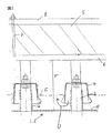
図1はトレイ1とトレイ2の二つのトレイを示す。各トレイは、液体相がその上を越えて流れる堰11を端部に沿って有する板10から構成される。図1より分るように、例えば板10は塔槽(コラムハウジング)13に固定された支承12と、塔槽13の弦(chord)(図3参照)に沿って伸張する板である堰11に取り付けられたブラケット15の上に支持されている。
【0014】
板10は気体相が上昇して流れるための通路として作用する。この通路はトレイ1とトレイ2の板10に設けられた孔3であり、その孔3は、図1には示されていない円筒形の管16により上方に伸張しているが、この孔3は各トレイの板10の全面にわたって設置されているものとする。通路3は、下向きに開いた蓋4により覆われており、これにより気体は図2において矢印Dに示すように各トレイ上の液体の中を通過して上方に向かい気泡となる。蓋4は図2の一点鎖線Eで示される液面の下で開いている。もちろん、液面の高さは板10の上にある堰11の高さにより決定される。液面E上の領域Fの空間には、液体を介しての気体の気泡化により形成されていて分離器6により形成が制限された泡沫が充満する。その空間においては、気泡または泡沫の層はより大きく成長可能となるが、飛沫同伴防止用充填物5によりその成長は抑制される。
【0015】
本装置の最下段トレイから液体を捕集するために捕集装置(コレクタ)16が設けられても良い。
【0016】
図1において液体相を塔に取り入れる手段は矢印Bにより示されており、気体相を取り入れる手段は矢印Cにより示されている。
【0017】
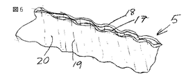
図2に示されるように、飛沫同伴防止充填物5と前置式分離器6はそれぞれトレイ1またはトレイ2の上部に架設するかまたは、上にあるトレイからロッド7及び圧縮パッドまたは押さえ金具8により懸架されており、圧縮パッドまたは押え金具8は飛沫同伴防止要素5の充填物板を保持する。飛沫同伴防止要素5は配列された(ordered)充填構造であっても良く、垂直に配向された多数の波形板17、18(図6参照)を具備可能であり、波形板17、18は例えば、互いに交差する直線の波形19と20を有しており、隣接する波形板は、それらのそれぞれのリブ(助材)又は波形の山でお互いに接触している。波形板の代わりに波形状の帯板を用いても良い。
【0018】
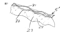
図7においては飛沫同伴防止要素として別のタイプの配列された充填物5’を示す。この例では板21と22は、互いに交差するが曲線となっている波形23と24を有する。
【0019】
前置式分離器6はまた平面的構造物を具備しても良く、図1においてそれぞれの前置式分離器6は塔槽13の内壁に取り付けられた支承25と、堰板11に固定された別の支承26との上に架設されるように示される。各前置式分離器6はトレイ1の上またはトレイ2の上且つ飛沫同伴防止要素5の下の位置に、下にあるトレイとの距離Aを保持して、トレイと飛沫同伴防止要素の両方に平行に配置される。概略図2に示すように、前置式分離器6は飛沫同伴防止充填物5の直下に設置することも可能である。すなわち飛沫同伴防止充填物5と前置式分離器6の間に間隙を設けない方法である。
【0020】
図1から分るように、各前置式分離器6は2つの格子27と28を具備できる。各格子は、間隔をもって配置された上部棒材または上部帯材29と、間隔をもって配置された下部棒材または下部帯材30と、から成る層を具備しており、下部棒材30は上部棒材29に直交、即ち交差している。格子28の上部帯材31と下部帯材32は、上部格子27の上部帯材29と下部帯材30に対して互い違いに配列され(staggered)ても良い。各格子の帯材どうしは溶接可能である。
【0021】
一般的には、いずれの場合でも、前置式分離器は、波形板または波形帯材を具備しても良く、それらの波形板又は帯材は、図4に示すような格子35の上部波形帯材33と下部波形帯材34のように層状態で配置され、お互いに交差する。
【0022】
図5に示すように前置式分離器用格子36は、その様な前置式分離器を形成するために使用される構造用型材の例として、上部溝型材37と、下部溝型材38とを具備する。
【0023】
図1,6,7から分るように、飛沫同伴防止要素すなわち充填物5はどんな場合でも、確実に泡沫層を破壊するので、泡沫層の形成高さを制限でき、気体による無制御の液体飛沫同伴を防ぐことができ、そして前置式分離器は各トレイ上における泡沫層の破壊と気液分離を促進する作用がある。
【0024】
実験によれば、トレイ上の充填物の並べ方及び流路の形状や傾斜にもよるが、処理能力が50%増加する可能性のあることが分かった。
【0025】
本発明は構造が簡単なので既にトレイが所定位置に取り付けられている既存の棚段塔であっても後付の改造が可能である。実際、ほとんどの棚段塔は、飛沫同伴防止充填物および、または前置式分離器を既存の固定用具に容易に取り付けても良い。
【図面の簡単な説明】
【図1】図1は、本発明の第一の実施の形態の部分図式図である。
【図2】図2は、第二の実施の形態の図式拡大図であり、気体相が通過するトレイに設けられた開孔の詳細を示す。
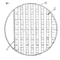
【図3】図3は、図1の線III −III に沿う断面図である。
【図4】図4は、本発明の別の実施の形態における分離器の上部層の一つを成す格子の断面図である。
【図5】図5は、本発明の別の実施の形態に従う分離器の層の一つの格子の断面図である。
【図6】図6は、飛沫同伴防止充填物の部分図式図である。
【図7】図7は、別の飛沫同伴防止充填物の一部分の図6と同様な図である。
【符号の説明】
1…トレイ
2…トレイ
3…孔
4…蓋
5…飛沫同伴防止充填物(要素)
6…分離器
7…ロッド
8…押さえ金具
10…板
11…堰
12…支承
13…塔槽
15…ブラケット
29…上部棒材又は帯材
30…下部棒材又は帯材
31…上部棒材又は帯材
32…下部棒材又は帯材[0001]
TECHNICAL FIELD OF THE INVENTION
The present invention relates to a tray column for performing mass transfer or heat exchange between a gaseous phase and a liquid phase, and more particularly to a tray for mass transfer and / or heat exchange and a tray arranged between such trays. To a column provided with a detent entrainment element or packing.
[0002]
[Prior art]
Conventionally, tray columns are often used for heat exchange between liquid and gas and mass transfer processes.
[0003]
The liquid forms a layer on the tray and overflows from one tray to the next. The liquid generally descends in the column, while the gas passes through the liquid layer on the tray and rises in the column. As the gas passes through the liquid layer through the apertures provided in the tray, the movement of the gas may form a bubble or foam layer on the liquid surface on the tray or on the tray itself. It is not preferable that a bubble layer of bubbles or foam reaches from the lower tray to the upper tray. U.S. Pat. Nos. 5,262,094 and 5,762,668 disclose an anti-entrainment element between the lower tray and the upper tray and below the tray, i.e., a measure using a filler. . The droplet entrainment preventing element is a packing called a demister or a gas-liquid separator.
While such devices (systems) are effective, they are not satisfactory in all cases.
[0004]
[Problems to be solved by the invention]
Therefore, an object of the present invention is to further restrict a foam or a bubble layer in a tray tower, and to make it possible to arrange tray trays of the tray tower closer to each other.
[0005]
The present invention minimizes the pressure drop in the column, and can limit as much as possible the formation of bubbles or bubbles on the liquid layer on a tray to reach the next tray, so that the gas phase and the liquid phase Another object is to provide a column that performs mass transfer and / or heat exchange between the column.
[0006]
Still another object of the present invention is to provide a tray column capable of improving gas-liquid separation efficiency while minimizing pressure loss.
[0007]
[Means for Solving the Problems]
These objects are achieved conventionally by placing the anti-entrainment elements as fillers in the upper and lower trays, i.e. between the two trays, and adding a front separator. The pre-separator is composed of a sheet-like metal plate or a structural mold (shape) arranged at a distance from a mass transfer tray and / or at least one lattice. More particularly, columns that perform mass transfer or heat exchange between the gas and liquid phases are:
A vertical column with means for raising the gas phase and lowering the liquid phase in the column,
A plurality of trays vertically spaced in the tower vessel, wherein the lower tray and a lower tray supporting a layer of the liquid phase and raising the gas phase through the layer. A plurality of trays, comprising: an upper tray disposed at intervals on the tray, wherein the plurality of trays wherein the liquid phase flows down from tray to tray;
An anti-entrainment element located in the tower vessel between the lower and upper trays for separating gas and liquid and prior to the passage of gas through the upper one of the two trays; ,
In the tower tank, a pre-separator under the droplet entrainment preventing element and arranged at an interval from the tray,
Is provided.
[0008]
The preseparator is generally planar and is spaced below the anti-entrainment element and comprises a sheet metal plate or structural profile or foil or at least one grid.
[0009]
The preseparator comprises a corrugated metal plate or strip which can be arranged parallel to the tray.
[0010]
The pre-separator may include a member installed on one layer and intersecting a layer installed on another layer. The pre-separator can be suspended from an overlying anti-entrainment element or from a tray, and the anti-entrainment packing and the pre-separator can both be suspended from an overlying tray. It is. The packing may have vertically arranged corrugated plates, which are adjacent to each other and which are inclined in the opposite direction and extend linearly or along a curve. And the corrugations of adjacent plates.
[0011]
The front separator according to the invention is arranged between the upper anti-entrainment element and the lower tray, so that the anti-entrainment element is not overloaded and is not so dense Alternatively, since it is not necessary to pack the packing firmly, the pressure drop in the column can be reduced. The anti-entrainment packing and the pre-separator can work together to reduce the spacing between trays and increase the efficiency of heat and / or mass exchange. Back mixing of the liquid can be reliably prevented, and the distribution of the liquid on the tray is also improved. Moreover, such a pre-separator can easily be retrofitted to existing tray columns provided with anti-entrainment packing.
[0012]
The above and other objects, forms and advantages will become more readily apparent from the following description taken in conjunction with the accompanying drawings.
[0013]
BEST MODE FOR CARRYING OUT THE INVENTION
FIG. 1 shows two trays, tray 1 and tray 2. Each tray is composed of a
[0014]
The
[0015]
A collecting device (collector) 16 may be provided to collect the liquid from the lowermost tray of the present device.
[0016]
In FIG. 1, the means for introducing the liquid phase into the column is indicated by arrow B, and the means for introducing the gas phase is indicated by arrow C.
[0017]
As shown in FIG. 2, the
[0018]
In FIG. 7 another type of arranged packing 5 'is shown as an anti-entrainment element. In this example,
[0019]
The
[0020]
As can be seen from FIG. 1, each
[0021]
In general, in each case, the pre-separator may comprise corrugated plates or corrugated strips, which corrugated plates or corrugated strips are provided on top of the
[0022]
As shown in FIG. 5, the pre-separator grid 36 comprises an
[0023]
As can be seen from FIGS. 1, 6 and 7, the anti-entrainment element or filling 5 in any case reliably destroys the foam layer, so that the formation height of the foam layer can be limited and the uncontrolled liquid by gas Splash entrainment can be prevented, and the front separator has the effect of promoting the destruction of the foam layer and gas-liquid separation on each tray.
[0024]
Experiments have shown that the processing capacity may increase by 50%, depending on the arrangement of the packing materials on the tray and the shape and inclination of the flow path.
[0025]
Since the present invention has a simple structure, retrofitting can be retrofitted even to an existing tray tower in which a tray is already mounted at a predetermined position. In fact, most tray columns may easily attach anti-entrainment packing and / or pre-separator to existing fixtures.
[Brief description of the drawings]
FIG. 1 is a partial schematic diagram of a first embodiment of the present invention.
FIG. 2 is a schematic enlarged view of the second embodiment, showing details of an opening provided in a tray through which a gas phase passes.
FIG. 3 is a sectional view taken along line III-III in FIG. 1;
FIG. 4 is a cross-sectional view of a grating forming one of the upper layers of a separator according to another embodiment of the present invention.
FIG. 5 is a cross-sectional view of one grid of layers of a separator according to another embodiment of the present invention.
FIG. 6 is a partial schematic diagram of the anti-entrainment packing.
FIG. 7 is a view similar to FIG. 6 of a portion of another anti-entrainment packing;
[Explanation of symbols]
DESCRIPTION OF SYMBOLS 1 ... Tray 2 ...
6 Separator 7
Claims (13)
該塔内において気体相を上昇させ且つ液体相を下降させるための手段を備えた竪型塔槽と、
該塔槽内において垂直方向に間隔をもって配置される複数のトレイであって、下部トレイと、前記液体相の層を保持していて前記気体相を該層を通過して上昇させるための該下部トレイ上に間隔を持って配置される上部トレイと、を具備する複数のトレイであって、前記液体相はトレイからトレイへと流下する複数のトレイと、
該下部と上部のトレイの間で該塔槽内にあって前記下部トレイ上で気体から液体を分離するために且つ該2つのトレイの内の上部トレイを通る気体の通過の前に配置された飛沫同伴防止要素と、更に
該塔槽内において、該飛沫同伴防止要素の下にあって且つ該トレイと間隔をもって配置される前置式分離器と、
を具備する塔。In a column for performing mass transfer or heat exchange between a gas phase and a liquid phase, the column comprises:
A vertical tower tank provided with means for raising the gas phase and lowering the liquid phase in the column;
A plurality of trays vertically spaced in the tower vessel, comprising a lower tray and a lower holding a layer of the liquid phase and raising the gaseous phase through the layer. A plurality of trays, comprising: an upper tray disposed at intervals on the tray, wherein a plurality of trays wherein the liquid phase flows down from tray to tray;
Disposed between the lower and upper trays in the tower vessel to separate liquid from gas on the lower tray and prior to passage of gas through the upper one of the two trays. A splash-prevention element, and further a front-end separator disposed in the tower tank below the splash-prevention element and spaced from the tray;
A tower comprising:
該波形板は、互いに接する隣接する波形板の山と、逆方向に傾く隣接する波形板の波形と、
を有する請求項10記載の塔。Each of the anti-entrainment elements is a filling of a vertically arranged corrugated plate,
The corrugated plate, the peaks of adjacent corrugated plates in contact with each other, the waveform of adjacent corrugated plates inclined in the opposite direction,
11. The tower according to claim 10, comprising:
Applications Claiming Priority (1)
| Application Number | Priority Date | Filing Date | Title |
|---|---|---|---|
| DE10230325A DE10230325A1 (en) | 2002-07-05 | 2002-07-05 | tray column |
Publications (2)
| Publication Number | Publication Date |
|---|---|
| JP2004034026A true JP2004034026A (en) | 2004-02-05 |
| JP2004034026A5 JP2004034026A5 (en) | 2005-11-24 |
Family
ID=29719478
Family Applications (1)
| Application Number | Title | Priority Date | Filing Date |
|---|---|---|---|
| JP2003187374A Pending JP2004034026A (en) | 2002-07-05 | 2003-06-30 | Plate tower equipped with entrainment prevention packings under tray |
Country Status (4)
| Country | Link |
|---|---|
| US (1) | US20040099970A1 (en) |
| EP (1) | EP1378281A1 (en) |
| JP (1) | JP2004034026A (en) |
| DE (1) | DE10230325A1 (en) |
Families Citing this family (12)
| Publication number | Priority date | Publication date | Assignee | Title |
|---|---|---|---|---|
| US8317035B2 (en) * | 2004-12-30 | 2012-11-27 | Global Nuclear Fuel-Americas, Llc. | Debris filter |
| FR2909894B1 (en) | 2006-12-14 | 2010-12-17 | Inst Francais Du Petrole | DEFLECTOR SYSTEM FOR COLUMN TRAYS |
| US8020838B2 (en) * | 2009-03-31 | 2011-09-20 | Uop Llc | Contacting stages for co-current contacting apparatuses |
| FR2943924B1 (en) | 2009-04-03 | 2011-04-01 | Inst Francais Du Petrole | COLUMN AND GAS-LIQUID CONTACT METHOD USING A COMBINATION OF TRAYS AND TRIMS |
| CN105026006B (en) * | 2013-01-16 | 2017-06-06 | 苏舍化学技术有限公司 | Mixing for mass transfer tower contacts pallet |
| CN105026005B (en) * | 2013-01-16 | 2017-05-31 | 苏舍化学技术有限公司 | Mixing for mass transfer tower contacts pallet |
| DE102013107357A1 (en) | 2013-07-11 | 2015-01-15 | L'Air Liquide, Société Anonyme pour l'Etude et l'Exploitation des Procédés Georges Claude | Liquid redistributor |
| RU2602863C9 (en) * | 2015-07-10 | 2017-03-22 | Игорь Анатольевич Мнушкин | Mass exchange tower with cross current of system liquid and gaseous phases |
| US11786855B2 (en) * | 2018-03-29 | 2023-10-17 | Uop Llc | Vapor-liquid contacting apparatus and process with downcomer at shell |
| CN111686539A (en) * | 2019-03-15 | 2020-09-22 | 招远市汇潮新能源科技有限公司 | Gas purification method and system |
| CN110697880B (en) * | 2019-11-14 | 2021-04-06 | 徐书敏 | Tower type biological filter |
| CN114425208B (en) * | 2020-09-17 | 2022-11-11 | 中国石油化工股份有限公司 | Scale pan and dirty gas purification device |
Family Cites Families (17)
| Publication number | Priority date | Publication date | Assignee | Title |
|---|---|---|---|---|
| US1748508A (en) * | 1925-07-24 | 1930-02-25 | Atlantic Refining Co | Method of fractionation |
| US1748704A (en) * | 1925-11-24 | 1930-02-25 | Atlantic Refining Co | Fractionating column |
| US1962153A (en) * | 1931-06-18 | 1934-06-12 | Atlantic Refining Co | Fractional distillation |
| US2476095A (en) * | 1944-06-05 | 1949-07-12 | Kellogg M W Co | Fractionating apparatus |
| US2832578A (en) * | 1953-12-21 | 1958-04-29 | Phillips Petroleum Co | Vapor-liquid contacting apparatus |
| US2862697A (en) * | 1955-11-21 | 1958-12-02 | Shell Dev | Contacting tray with downcomerfeeder |
| US2877099A (en) * | 1956-08-15 | 1959-03-10 | Socony Mobil Oil Co | Multistage concurrent-countercurrent liquid gas contact and apparatus therefor |
| SE325589B (en) * | 1967-02-21 | 1970-07-06 | C G Munters | |
| US3779524A (en) * | 1971-08-10 | 1973-12-18 | Mitsui Shipbuilding Eng | Gas-liquid contacting apparatus |
| US3887665A (en) * | 1973-04-20 | 1975-06-03 | Thomas William Mix | Vapor-liquid contacting |
| US4105723A (en) * | 1976-05-24 | 1978-08-08 | Merix Corporation | Vapor-liquid contacting |
| US4381974A (en) * | 1981-09-08 | 1983-05-03 | Furzer Ian A | Distillation columns |
| US5262094A (en) * | 1990-05-25 | 1993-11-16 | Uop | Fractionation tray having packing immediately below tray deck |
| US5366666A (en) * | 1990-05-25 | 1994-11-22 | Uop | Multiple downcomer fractionation tray having packing between downcomers |
| US5407605A (en) * | 1993-12-16 | 1995-04-18 | Uop | Fractionation tray with side discharging triangular downcomers |
| US5762668A (en) * | 1996-07-24 | 1998-06-09 | Glitsch, Inc. | Apparatus and method for deentrainment in a chemical process tower |
| US20010015136A1 (en) * | 2000-02-16 | 2001-08-23 | Letzel Hugo Martijn | Column for counter-currently contacting gas and liquid |
-
2002
- 2002-07-05 DE DE10230325A patent/DE10230325A1/en not_active Withdrawn
-
2003
- 2003-05-14 EP EP03010749A patent/EP1378281A1/en not_active Withdrawn
- 2003-06-17 US US10/463,838 patent/US20040099970A1/en not_active Abandoned
- 2003-06-30 JP JP2003187374A patent/JP2004034026A/en active Pending
Also Published As
| Publication number | Publication date |
|---|---|
| US20040099970A1 (en) | 2004-05-27 |
| EP1378281A1 (en) | 2004-01-07 |
| DE10230325A1 (en) | 2004-01-15 |
Similar Documents
| Publication | Publication Date | Title |
|---|---|---|
| EP0737498B1 (en) | Gas-liquid contacting tray with side discharging triangular downcomers | |
| US5262094A (en) | Fractionation tray having packing immediately below tray deck | |
| AU718717B2 (en) | Co-current contacting separation tray design and methods for using same | |
| RU2370299C1 (en) | Method and device of direct flow vapour-fluid contact treatment | |
| US7125004B2 (en) | Liquid distributor for use in mass transfer column | |
| KR101044979B1 (en) | Liquid collector and redistributor for packed columns | |
| JP4557490B2 (en) | Efficiency enhanced fractionation tray and process | |
| US9909824B2 (en) | Distributor in mass transfer column and method of use | |
| CN104245074B (en) | For the cross-flow type tower tray and supporting system of mass transfer column | |
| US5366666A (en) | Multiple downcomer fractionation tray having packing between downcomers | |
| JP2004034026A (en) | Plate tower equipped with entrainment prevention packings under tray | |
| WO2002083260A2 (en) | Liquid distributor in mass transfer column and method of installation and use | |
| JP6207031B2 (en) | Liquid dispensing device | |
| TW384235B (en) | The deentrainment assembly and the method a chemical process | |
| JP2005066594A (en) | Apparatus for collecting and redistributing flow of liquid descending in exchanging column | |
| US20030090009A1 (en) | Liquid distributor and method for operating the same | |
| US6131891A (en) | Fractionation column containing stacked fractionation trays | |
| JP4523220B2 (en) | Packing for heat exchange column and mass exchange column | |
| US5387377A (en) | Active liquid distributor containing packed column | |
| KR20110031490A (en) | Downcomer for a gas-liquid contacting device | |
| KR20200133791A (en) | Vapor-liquid contact apparatus and method with offset contact modules | |
| US6095504A (en) | Supports for stacked fractionation tray end pieces | |
| KR20200133780A (en) | Vapor-liquid contact device and method with cross contact | |
| JPH02245202A (en) | Gas-liquid contact tray | |
| CN202122898U (en) | Gas-liquid redistributor |
Legal Events
| Date | Code | Title | Description |
|---|---|---|---|
| A621 | Written request for application examination |
Free format text: JAPANESE INTERMEDIATE CODE: A621 Effective date: 20050707 |
|
| A521 | Written amendment |
Free format text: JAPANESE INTERMEDIATE CODE: A523 Effective date: 20051006 |
|
| A977 | Report on retrieval |
Free format text: JAPANESE INTERMEDIATE CODE: A971007 Effective date: 20070406 |
|
| A131 | Notification of reasons for refusal |
Free format text: JAPANESE INTERMEDIATE CODE: A131 Effective date: 20070724 |
|
| A02 | Decision of refusal |
Free format text: JAPANESE INTERMEDIATE CODE: A02 Effective date: 20071218 |


