JP2004025468A - Tape printer - Google Patents
Tape printer Download PDFInfo
- Publication number
- JP2004025468A JP2004025468A JP2002181191A JP2002181191A JP2004025468A JP 2004025468 A JP2004025468 A JP 2004025468A JP 2002181191 A JP2002181191 A JP 2002181191A JP 2002181191 A JP2002181191 A JP 2002181191A JP 2004025468 A JP2004025468 A JP 2004025468A
- Authority
- JP
- Japan
- Prior art keywords
- imaging
- data
- tape
- unit
- Prior art date
- Legal status (The legal status is an assumption and is not a legal conclusion. Google has not performed a legal analysis and makes no representation as to the accuracy of the status listed.)
- Pending
Links
Images


Abstract
Description
【0001】
【発明の属する技術分野】
本発明は、入力したテキストデータおよび撮像データを含む印刷データに基づいて、装着した印刷テープに印刷を行うテーププリンタ、特に撮像手段を備えたテーププリンタに関するものである。
【0002】
【従来の技術】
従来のテーププリンタにおいて、被写体を撮像することによって得られる撮像データ(写真)の入力は、撮像データを有するパーソナルコンピュータやデジタルカメラ等の外部装置にテーププリンタを接続して、外部装置から所望する撮像データをダウンロードするか、メモリカードのような撮像データを記憶する外部メモリをテーププリンタに装着することにより行われていた。
【0003】
【発明が解決しようとする課題】
すなわち、従来のテーププリンタは、外部装置を介さなければ撮像データを入力することができないため、ユーザがテーププリンタで撮像データを印刷しようとするときには、外部装置とテーププリンタとを接続した上で、テーププリンタおよび外部装置両方の操作を行わなければならず、ユーザは面倒な操作を行わなければならなかった。その上、外部装置を介して入力した撮像データと印刷テープの幅が対応していないために、撮像データを適切に印刷するには、印刷テープの幅に合わせて撮像データの印刷サイズを手動で設定する必要があり、ユーザは煩雑な操作を強いられていた。
【0004】
そこで、本発明は、被写体を撮像して撮像データを直接入力できると共に、入力した撮像データを容易に印刷テープに印刷できるテーププリンタを提供することをその課題としている。
【0005】
【課題を解決するための手段】
本発明は、印刷データを入力するための入力手段と、印刷データを表示する表示手段と、入力した印刷データを編集可能な編集手段と、装着された印刷テープに印刷データに基づいた印刷を行う印刷手段と、印刷テープの幅を検出する検出手段と、を備え、入力手段は、被写体を撮像して被写体の撮像データを印刷データとして入力するための撮像手段と、テキストデータを前記印刷データとして入力するためのテキスト入力手段と、を有していることを特徴とするテーププリンタである。
【0006】
この構成によれば、テキストデータを入力できるだけでなく、撮像手段により撮像データを直接印刷データとして入力することができる。これにより、テキストデータのみならず撮像データも容易に入力可能となり、テキストデータと撮像データを合成することにより、作成できるラベルの表現力を飛躍的に高めることができる。
【0007】
この場合、撮像手段は、入力する撮像データの画質を設定する画質設定手段を備えたことを特徴とする。
【0008】
この構成によれば、画像設定手段で入力する撮像データの画質、すなわち画像データの粗さを設定することができる。したがって、ユーザは、撮像データの印刷サイズや装着されている印刷テープの幅を考慮しながら画質を設定することができ、ユーザの目的に応じた撮像データの画質設定が可能である。なお、画質がよくなるほど、すなわち画像データの粗さが細かくなるほど処理時間が長くなるので、ユーザの目的に応じて撮像データの画質を設定可能とすることで、処理時間を最適化することができる。
【0009】
この場合、画質設定手段は、検出手段により検出した印刷テープの幅に応じて、入力する撮像データの画質を設定することが好ましい。
【0010】
この構成によれば、画質設定手段により、印刷テープの幅に応じて自動的に撮像データの画質を設定できるので、印刷テープ幅に応じた適切な画質に容易に設定することができる。具体的には、印刷した画像データの印刷サイズが大きくなるほど画像データの粗さが目立つので、画質設定手段では印刷テープの幅が大きくなるほど多くの記録画素数を増やすようにする。
【0011】
これら場合、被写体を照明する照明手段を更に備えていることが好ましい。
【0012】
この構成によれば、照明手段によって、撮像のための光量を十分に確保することができ、鮮明な撮像データを得ることができる。したがって、撮像データを後に画像処理する場合等のように、撮像データを利用する際のユーザの自由度を高めることができる。
【0013】
これらの場合、画質は、撮像データの記録画素数および圧縮率によって規定されており、入力した撮像データと共に、当該撮像データの記録画素数および圧縮率を記憶する記憶手段をさらに備えることが好ましい。
【0014】
この構成によれば、撮像データと共に当該撮像データの記録画素数および圧縮率を記憶手段に記憶することができる。これにより、ユーザは、後に撮像データと併せて記録画素数および圧縮率を参照することができるようになり、これらを参考にして後の撮像を行うことができる。また、記録画素数および圧縮率と併せて撮像データを利用することが可能となる。
【0015】
これらの場合、撮像手段は、セルフタイマー機能を有していることが好ましい。
【0016】
この構成によれば、ユーザは、セルフタイマー機能により撮像指令から実際に撮像が行われるまでの時間をコントロールすることができる。
【0017】
この場合、表示手段は、被写体の撮像時にファインダーとして機能することが好ましい。
【0018】
この構成によれば、表示手段が被写体撮像時にファインダーとして機能するので、表示手段に被写体を映し出すことが可能となる。したがって、ユーザは、被写体の位置を確認して被写体の撮像位置を定めることができ、テープ上の画面構成を考慮した適切な撮像データを得ることができる。
【0019】
この場合、ファインダー機能は、撮像手段の撮像可能範囲を表示する撮像範囲表示機能を有していることが好ましい。
【0020】
この構成によれば、ファインダー機能が、撮像可能範囲を表示する撮像範囲表示機能を有しているので、この表示に基づいて被写体の撮像位置を的確に定めることができる。これにより、ユーザは、より的確に画面構成を定めることができるようになり、撮像前に撮像により得られる被写体の撮像データのイメージを把握して、より適切な撮像データを得ることができる。
【0021】
この場合、撮像範囲表示機能は、撮像可能範囲内に検出手段により検出した印刷テープの幅に対応させた枠を合成表示することが好ましい。
【0022】
この構成によれば、撮像可能範囲内に、検出手段により検出した印刷テープの幅に対応させた枠が合成表示されるので、ユーザは装着された印刷テープの幅を考慮しながら撮像することが可能である。すなわち、ユーザは、撮像データを装着した印刷テープに印刷した時のイメージを掴んだ上での撮像が可能となるため、目的にあった撮像データを得ることが可能となる。
【0023】
この場合、撮像手段は、画像情報を処理することにより撮像データを作成しており、撮像手段は、枠内に表示される画像に対応する画像情報のみを処理することが好ましい。
【0024】
この構成によれば、撮像可能範囲の枠内に表示される画像に対応する画像情報のみ、すなわち、印刷される印刷テープ幅に対応して必要な画像情報のみが処理(トリミング処理)されるので、撮像手段によって得られる画像情報を全て処理した場合に比べて、処理時間を短縮することができる。また、装着された印刷テープの幅に対応した撮像データが作成されるので、ユーザは後に行う撮像データの編集を円滑に行うことができる。
【0025】
この場合、印刷テープには、幅の異なる複数種のものが用意されており、編集手段は、撮像データの印刷サイズを、検出手段により検出した印刷テープの幅に対応した印刷サイズに設定可能に構成されていることが好ましい。
【0026】
この構成によれば、撮像データの印刷サイズを、装着している印刷テープに応じて自動的に設定することができる。したがって、ユーザは、撮像データを印刷テープの幅に応じた印刷サイズに設定するために、撮像データの縦および横の縮小率を考慮したうえで、印刷テープの幅を勘案するといった煩雑な操作を行わずにすむ。そして、撮像データの印刷サイズ設定に要する時間を短縮することができ、ユーザの利便性および操作性を向上させることができる。
【0027】
この場合、印刷データを外部装置に送信する通信手段を備えることが好ましい。
【0028】
この構成によれば、通信手段により印刷データを外部装置に送信することができるので、印刷データを外部装置に記憶させた後に再利用したり、印刷データを外部装置で編集することが可能となる。
【0029】
【発明の実施の形態】
以下、添付した図面を参照しながら、本発明の一実施形態となるテーププリンタについて説明する。
【0030】
図1は本実施形態におけるテーププリンタ全体の外観斜視図であり、図2は本実施形態におけるテーププリンタの開閉カバーを開放したときの外観斜視図である。図2に示すように、テーププリンタ1の前部上面部に、開閉カバー11が設けられており、開閉カバー11の内側には入力した印刷データを視認するためのディスプレイ101が備えられている。また、開閉カバー11の内側上部には、撮像手段41が設けられており、被写体を撮像するためのレンズ42が埋め込まれている。そして、テーププリンタ1の前部上面にはキーボード81が設けられており、図1に示すように、開閉カバー11を閉めるとキーボード81がカバーリングされるようになっている。なお、テーププリンタ1の上部手前右側には、電源キー12と、テーププリンタ1と接続した外部装置との通信を指示する通信キー13とが設けられ、上部手前左側には、テーププリンタ1の状況を示す表示ランプ14が複数(5つ)設けられている。
【0031】
また、テーププリンタ1の後部左上面には、開閉ボタン15により開放される開閉蓋16が設けられ、内部に印刷テープTを収容したテープカートリッジCを装着するためのポケット31が形成されている。そして、テーププリンタ1の左側面には、印刷済みの印刷テープTを排出するテープ排出口17が形成されており、テープ排出口17に臨んで印刷テープTを切断するためのテープカッタ113が設けられている。テーププリンタ1の右側面には、電源アダプターを差し込むための電源接続口18、およびテーププリンタ11と外部装置とを接続するための外部装置接続口19とが設けられている。
【0032】
図3に示すように、テーププリンタ1は基本的な構成として、キーボート81やディスプレイ101を備え、ユーザとのインターフェイスを行う操作部4、撮像手段41を有して被写体を撮像し、撮像データを入力する撮像部3、後述する印刷ヘッド34を備えて印刷を行う印刷部2、テープカッタ113により印刷後に印刷テープの切断を行う切断部5、各種センサを有して各種検出を行う検出部6、各種ドライバを介して各部を駆動する駆動部7、およびテーププリンタ1の各部を制御する制御部8を備えている。
【0033】
このテーププリンタ1は、ラベルを作成するためのもので、キーボード81等や撮像部3で被写体を撮像することにより入力された印刷データに基づいて、テープカートリッジCから印刷テープTを繰り出しながら、印刷テープTに印刷ヘッド34で印刷を行うと共に、印刷済みの印刷テープTをテープ排出口17から送り出し、印刷終了後に所定の位置で印刷テープTをテープカッタ113で切断することにより、ラベルを作成する。
【0034】
なお、このテーププリンタ1に用いられるテープカートリッジCは、印刷テープTとインクリボンRとを収容しており、収容する印刷テープTの幅等に合わせて複数種のものが用意されている。そして、テープカートリッジCには、ポケット31に装着したときに印刷ヘッド34が遊挿される貫通開口C1が設けられており、テープカートリッジCの裏面には、収容する印刷テープTの幅や種類を識別するための小孔(図示省略)が複数設けられている。
【0035】
印刷テープTは、裏面に形成された粘着面を剥離紙で覆われており、印刷後にラベルとして貼付できるようになっている。そして、印刷テープTは、幅が異なる複数種のものが用意されているだけではなく、テキストデータを印刷するための印刷テープTと、被写体を撮像することによって得た撮像データを高品位に印刷するための印刷テープTとが用意されている。なお当然のことながら、テキストデータを印刷するための印刷テープTであっても、撮像データを印刷可能である。
【0036】
印刷テープTとインクリボンRは、貫通開口C1の位置で相互に重なり合った状態で走行する。そして、印刷済みの印刷テープTのみがテープ排出口17から外部に排出され、インクリボンRは内部で巻き取られるようになっている(図1参照)。
【0037】
次に、テーププリンタ1の各構成について順に説明する。印刷部2は、印刷テープTを送り出しながら印刷を行うもので、図1に示すように、テープカートリッジCを装着するためのポケット31と、送りモータ32(図示省略)を駆動源としてテープカートリッジCから印刷テープTを繰り出しながら送るテープ送り部33と、ヘッドカバーで覆われると共にサーマルヘッドから構成される印刷ヘッド34とを備えている。印刷ヘッド34を発熱駆動させると文字等のキャラクタが印刷テープTに印刷され、これと同期してテープ送り部33は印刷テープTを適宜送り出している。
【0038】
なお、図示は省略したが、ポケット31には、テープカートリッジCが収容する印刷テープTの幅および種類を検出するテープ識別センサ121が設けられており、テープカートリッジCの裏面に設けられた小孔の配列(ビットパターン)を検出するようになっている。また、このテーププリンタ1にはこの他にも各種センサが設けられており、例えば、印刷ヘッド34の表面温度を検出するヘッド温度検出センサ123や、送りモータ32の回転速度を検出する回転速度センサ122が設けられている。
【0039】
撮像部3は、被写体を撮像して、被写体の撮像データを入力するためのもので、被写体を撮像するための撮像手段41と、被写体の撮像用に十分な光量を確保するためのストロボ71と、撮像手段41による撮像結果に基づいて撮像データを作成すると共に、撮像手段41およびストロボ71の駆動を制御する信号処理手段51と、を備えている。
【0040】
撮像手段41は、被写体撮像用のレンズ42と、レンズ42を覆ってレンズ42に入射する赤外線をカットする光学フィルター43と、撮像素子となるCCDイメージセンサ44(以下、CCD(Charge Coupled Device)とする)とを有している。撮像手段41は、前後左右に傾斜可能に取り付けられており、適切な角度で被写体を容易に撮像できるようになっている。CCD44は、2次元に配置され、レンズ42により結像した被写体像を電気信号に変換する。なお、本実施形態では撮像素子としてCCD44を用いているが、これに限られるものではなく、撮像素子としてCMOSイメージセンサや増幅型イメージセンサ等を用いてもよい。
【0041】
信号処理手段51は、制御部8の負荷を軽減し、撮像部3からの情報処理を高速に行うために設けられた専用ICで、図4に示すように、制御部8に接続されて、制御部8からの制御に基づいて撮像部3の制御を行うと共に、CCD44からの電気信号を処理して撮像データを展開する。そして、信号処理手段51には、撮像部3を制御する制御プログラムを記憶する撮像部用ROM52と、撮像データを展開・処理するすると共に保存するための作業領域および保存領域として用いられる撮像部用RAM53とが設けられている。
【0042】
撮像部用RAM53には、撮像データを保存するための撮像データ保存領域61、撮像した撮像データと対応させて撮像時の記録画素数や、ホワイトバランス、露出時間(シャッタースピード)等を記憶する撮像情報記憶領域62、CCDからの電気信号を処理して撮像データを展開する撮像データ展開領域63、展開した撮像データを画像データファイル形式(例えばJPEG形式)に変換処理を行うための撮像データ処理領域64等が設けられている。
【0043】
操作部4は、各種キーからなるキーボード81と、印刷データを含む印刷情報を表示する表示画面102を有するディスプレイ101とを備えている。キーボード81は、アルファベットキー群、記号キー群等を有する文字キー群82の他、各種動作を指定するための機能キー群83などが配列されている。
【0044】
機能キー群83には、印刷動作を指示するための印刷キー93、テキスト入力時のデータ確定や改行、選択画面における各種モードの選択指示のための選択キー94、各種指示を取り消すための取り消しキー92、各キーの役割変更等に用いられるシフトキー95、およびカーソル移動や表示画面102の表示範囲を移動させるための4個のカーソルキー96(96U、96D、96R、96L)が設けられている。また、キーボード81によるテキスト入力モードから、撮像部3による撮像モードに直接モード切換えをする入力切換キー97、撮像を指示するシャッターキー98、撮像モード時に押されると、表示画面102に撮像部3で撮像可能範囲201を表示させるプレビューキー99等を有している。
【0045】
ディスプレイ101は、入力したテキストデータおよび撮像した撮像データを視認したり、編集する際に用いられる。また、ディスプレイ101は、撮像データ入力モードに切り換わるとファインダーとして機能し、プレビューキー99により撮像可能範囲201の表示を行う。
【0046】
切断部5は、テープカッタ113として、印刷テープTを切断して切り離す(フルカットする)フルカット用カッタ113aと、印刷テープTまたは剥離紙のいずれか一方のみを切断する(ハーフカットする)ハーフカット用カッタ113bとを備えている。そして、切断部5は、フルカット用カッタ113aを有すフルカット手段111と、ハーフカット用カッタ113bを有すハーフカット手段112とを備えており、フルカット手段にはフルカット用カッタ113aを切断動作させるフルカット用カッタモータ114aが、ハーフカット手段112にはハーフカット用カッタ113bを切断動作させるハーフカット用カッタモータ114bが備えられている。そして、印刷テープTは、ハーフカット手段112でハーフカットされた後、フルカット手段111でフルカットされてテープ排出口17から排出される。
【0047】
検出部6は、前述のテープ識別センサ121、回転速度センサ122、ヘッド温度検出センサ123など各種センサを備えている。そして、各種センサからの検出信号を制御部8に送り、これに基づいて制御部8が各部を制御できるようにしている。なお、これらのセンサは実状に合わせて設ければよい。例えば、光量を検出するセンサを設け、検出した光量に基づいて上記したストロボ71を自動点灯させるようにしてもよい。
【0048】
駆動部7は、制御部8から出力される制御信号に基づいて、各部を駆動するもので、ディスプレイ101を駆動するディスプレイドライバ131や、印刷ヘッド34を駆動するヘッドドライバ132、テーププリンタ1内の各モータを駆動するモータドライバ133等を有している。
【0049】
制御部8は、CPU141、ROM142、キャラクタジェネレーションROM(CG−ROM)143、RAM144、周辺制御回路(P−CON)145を備え、互いに内部バス146により接続されている。ROM142は、CPU141で処理する制御プログラムを記憶する制御プログラム領域の他、色変換テーブルや文字修飾テーブルなどを含む制御データを記憶する制御データ領域を有している。CG−ROM143はテーププリンタ1に用意されている文字、記号、図形等のフォントデータを記憶していて、文字等を特定するコードデータが与えられたときに、対応するフォントデータを出力する。
【0050】
RAM144は、電源キー12の操作により電源がオフにされても、記憶したデータを保持しておくようにバックアップ回路(図示省略)によって電源の供給を受けており、各種レジスタ群や、表示画面102の表示画像データを記憶する表示画像データ記憶領域、描画登録画像データを記憶する描画登録画像データ領域の他、印刷履歴データ領域やその他の色変換バッファなどの各種変換バッファ領域などの領域を有し、制御処理のための作業領域として使用される。
【0051】
また、RAM144は、ユーザが設定した記録画素数や露出時間等の撮像条件を記憶する撮像条件記憶領域151や、撮像部RAMの撮像データ保存領域、画像データファイル形式に変換した撮像データを記憶する変換撮像データ保存領域、撮像情報記憶領域、撮像データ展開領域、および撮像データ処理領域等から転送された情報を記憶するための記憶領域を有している。
【0052】
P−CON145には、タイマー146や、CPU141の機能を補うと共に周辺回路とのインターフェイス信号を取り扱うための論理回路、ゲートアレイやカスタムLSIなどが組み込まれている。P−CON145は、各種センサやキーボード81と接続され、各種検出信号およびキーボード81からの各種指令や印刷データなどをそのまま、あるいは加工して内部バス147に取り込むと共に、CPU141と連動して、CPU141等から内部バス147に出力されたデータや制御信号をテーププリンタ1各部に出力する。
【0053】
そして、CPU141は、ROM142内の制御プログラムに従って、P−CON145を介して各種検出信号、各種指令、各種データ等を入力して、CG−ROM143からのフォントデータ、RAM144内の各種データ等を処理し、P−CON145を介して制御信号をテーププリンタ各部に出力する。具体的には、ユーザの設定に基づいて、信号処理手段51を介して撮像部3を制御して撮像を行ったり(図4参照)、印刷の位置制御や表示画面102の表示制御等を行うと共に、印刷ヘッド34を制御して所定の印刷条件で印刷テープTに印刷を行うなど、CPU141は、テーププリンタ1全体を制御している。
【0054】
また、このテーププリンタ1は、外部装置接続口19を介してパーソナルコンピュータなどの外部装置と接続して通信可能に構成されており、RAM144内に記憶したテキストデータや撮像データ等を含む印刷データを外部装置に送信することが可能である。また、外部装置に記憶されているテキストデータ等を印刷データとして受信することも可能である。なお、このテーププリンタ1には、外部装置と通信を行うための通信モードに切替えるための通信キー13が設けられている。
【0055】
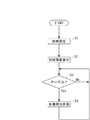
次に、テーププリンタ1の制御全体の処理フローについて図5を参照しながら説明する。まず、電源が入れられるなどして処理が開始すると、要求されている初期状態にテーププリンタ1を戻すための初期設定が行われ(S1)、次に、表示画面に初期画面が表示される(S2)。初期画面表示が終了して、キー入力割込みが許可されると、キー入力割込み待機状態(S3:No)となり、キー入力が可能となる。キー入力によりキー入力割り込みが発生すると(S3:Yes)、割込み処理に移行し(S4)、その割込み処理が終了すると、再度キー入力割り込み待機状態(S3:No)となる。なお、キー入力されたか否かの判断分岐(S3)および各種割込み処理(S4)は、概念的に示した処理である。
【0056】
このようにテーププリンタ1では、主な処理を割込み処理によって行うので、印刷画像作成準備および印刷の準備ができていれば、ユーザが任意の時点で印刷キー93を押すことにより、印刷処理割込みが発生して、印刷処理が起動して印刷がなされるので、ユーザは印刷に至るまでの操作手順を任意に選択できる。
【0057】
ところで、このテーププリンタ1では、キーボード81によるテキストデータと、撮像部3によって被写体を撮像することによって得た撮像データとを印刷データとすることができるようになっている。そして、入力切換キー97を押すことにより、テキスト入力モードと撮像モードとのモード切替えが直接なされると共に、表示画面102の切換えがなされる。なお、テキスト入力モードでは、表示画面102はテキスト入力画面を表示してキーボード81から入力されたテキストデータを視認できるようになっており、撮像モードにおいてはファインダーとして機能して、表示画面102に被写体を映し出し、撮像する被写体の位置を確認できるようになっている。
【0058】
そこで、本願発明と関連する撮像部3による被写体の撮像手順、および撮像した撮像データの編集方法について説明する。
【0059】
まず、撮像部3による被写体の撮像手順について説明する。最初に入力切換キー97を押して、撮像モードに切替えると共に、表示画面102をファインダーとして機能させる。次に、被写体にレンズ42を向け、前後左右に傾斜させながら表示画面上に被写体を映し出させ、表示画面102上に表示される被写体の位置を確認した後、シャッターキー98を押す。これにより、被写体の撮像が行われて、被写体の撮像データを得ることができる。なお、撮像部3は制御部8によって制御されており、制御部8(P−CON145)のタイマー146に基づいて撮像を行うことが可能となっている(図3参照)。
【0060】
なお、このテーププリンタ1では、撮像モード(図6(a)参照)でシャッターキー98を押す前にプレビューキー99を押す(S11)ことにより、表示画面102に撮像可能範囲201、すなわち、撮像手段41に実際に撮像されて撮像データを得ることができる範囲、を表示することができるようになっており(図6(b)参照)、ユーザは、撮像によって得ることができる撮像データのイメージを掴むことができると共に、これに基づいて画面構成を考え、被写体を撮像する際の位置決めをすることができる。そして、表示画面102に撮像可能範囲201が表示されている状態でもう一度プレビューキー99を押す(S12)と、撮像可能範囲201と共に、装着されている印刷テープTの幅と対応させた枠202が合成表示される(図6(c)参照)。これにより、ユーザは、印刷テープTの幅と関連付けて撮像データをイメージすることができ、ユーザの目的にあった撮像データを撮像可能となる。なお、撮像可能範囲201と共に表示される枠202の位置は、カーソルキー96によって上下移動させて表示させることが可能である。
【0061】
次に、撮像条件の設定、および撮像データの設定について説明する。このテーププリンタ1では、撮像前に、撮像条件設定メニューにより撮像条件を設定して、好みの条件で撮像ができるようになっている。撮像条件設定メニューでは、メニュー項目として、自動的に撮像条件を設定する「自動」の他、撮像時の光源に応じてホワイトバランスを設定する「ホワイトバランス」や、シャッタースピード(露出時間)を設定する「シャッタースピード」、ストロボ71を用いて撮像することを設定する「ストロボ」を有している。
【0062】
撮像によって得られる撮像データの画質は、記録画素数および画像データファイル形式に変換する際の圧縮率に規定されており、記録画素数が大きく、圧縮率が小さいほど鮮明は撮像データを得ることができるようになっている。そこで、本実施形態のテーププリンタ1には、ユーザの好みや必要性に応じて、記録画素数および圧縮率を設定するための画質設定メニューを設けられている。画質設定メニューには、記録画素数を設定するためのメニュー項目「記録画素数」、および圧縮率を設定するためのメニュー項目「圧縮率」が設けられている。そして、設定を容易に行うことができるように、「記録画素数」および「圧縮率」のそれぞれに対応した複数の選択肢が設けられている。
【0063】
また、撮像データの印刷サイズが大きいほど鮮明な撮像データが必要となるので、装着された印刷テープTの幅が大きいほど大きな印刷サイズが必要であるとみなして、装着された印刷テープTの幅に応じて、「記録画素数」および「圧縮率」を自動的に設定するメニュー項目「自動」が設けられている。すなわち、「自動」では、幅の大きな印刷テープTほど記録画素数を多く設定し、圧縮率を小さめに設定する。
【0064】
また、このテーププリンタ1では、被写体の撮像前に、撮像データのサイズを選択して、CCD44からの電気信号の処理方法を選択できるようになっており、選択肢として、CCD44からの電気信号を全て処理して、撮像データを作成する「全処理」と、CCD44からの電気信号の一部分を処理して、装着した印刷テープTの幅と対応したサイズの撮像データを作成する「テープ幅対応処理」とを有している。「テープ幅対応処理」では、上述した撮像可能範囲201と共に表示される枠202内に表示される部分の画像を撮像データとして展開するようにしており、枠202内に表示される部分に対応するCCD44からの電気信号のみを取り出して処理し、撮像データを作成している。
【0065】
「テープ幅対応処理」では、CCD44から得られる電気信号の一部分、すなわち装着した印刷テープTの幅に対応する部分の電気信号のみを処理して撮像データを展開するので、処理時間を短縮することが可能である。特に、全てのCCD44の電気信号を処理することで得られる撮像データの一部分のみを使用したい場合に有効である。また、印刷テープTの幅に対応した撮像データを得ることができるので、後の編集作業を円滑に行うことができる。
【0066】
なお、「テープ幅対応処理」では、撮像可能範囲201と共に表示された枠202の位置に基づいて処理を行っているので、カーソルキー96によって枠202を上下に移動表示させ、移動させた枠202の位置に基づいて処理を行うことができる。すなわち、カーソルキー96によって、容易に「テープ幅対応処理」が行われる位置を調整して、ユーザの目的にあった撮像データを作成することができる。また、本実施形態では、印刷テープTの幅に対応する部分の電気信号のみを処理するようにしているが、例えば、撮像可能範囲201の画像から必要な部分を選択して、選択した部分に対応するCCD44からの信号のみを処理するようにしても同様の効果を得ることができる。
【0067】
続いて、撮像データの編集方法について説明する。このテーププリンタ1では、撮像データを印刷テープTに印刷するまでのユーザの一連の操作を円滑にするために、撮像データを編集するための撮像データ編集メニューが設けられている。
【0068】
撮像データ編集メニューには、撮像データの印刷サイズ、すなわち撮像データを印刷テープTに印刷したときのサイズを設定するためのサイズ設定メニューが設けられている。そして、サイズ設定メニューには、装着された印刷テープTの幅に収まるよう自動的に撮像データの印刷サイズを設定するための選択肢として、装着された印刷テープTの幅に対応して撮像データの印刷サイズを設定する相対サイズが設けられており、撮像データの印刷サイズを装着された印刷テープTの幅に合わせて容易に設定可能となっている。なお、当然のことながら、サイズ設定メニューには、装着された印刷テープTをはみ出す印刷サイズに撮像データを設定することできるようになっており、例えば、撮像データを装着された印刷テープTの幅よりも大きく設定した上で、所望の部分を切り取り、その部分のみを印刷させることも可能である。また、撮像データに、修飾枠を付すためのメニューも用意されている。
【0069】
また、このテーププリンタ1では、撮像データの一部を選択して切り取ったり、選択した一部分を編集・加工することができるようになっている。
【0070】
最後に、具体例を挙げながら、テーププリンタ1における撮像データの利用方法について説明する。例えば、持ち物のラベルを作成する場合、持ち物の所有者を撮像して撮像データを得(図7(a)参照)、「私の持ち物」というテキストデータと所有者の撮像データとを合成して、ラベルに印刷することにより、所有者を容易に特定可能なラベルを作成可能となる(図7(b)参照)。また、収納物を示すラベルを作成する場合、収納物の撮像データをラベルに印刷すれば、よりわかりやすいラベルを作成することができる。例えば、図7(c)に示すように、六角フランジボルトを収納するためのラベルを作成する場合、「六角フランジボルト」と印刷することに加え、六角フランジボルトの撮像データを印刷すれば、六角フランジボルトの名称と形状が一致しない場合であっても、六角フランジボルトの撮像データにより六角フランジボルトの判断が可能となる。
【0071】
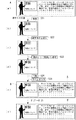
また、図8(a)に示すように、図形と文字が混在する文書中に誤字がある場合、文書の誤字の部分にだけ修正した文字のラベルを貼ると、図形とラベルの端とが重なって文書の見栄えが悪くなることがある。しかし、本実施形態のテーププリンタ1を用いれば、図形入りの修正用のラベルを作成して文書の修正部分に貼付することができるため、係るような問題は生じない。具体的には、図8(a)に示すように、まずAの部分、すなわち誤字の部分と図形とを併せて撮像し(S21)、撮像データを得る(図8(b)参照)。次に、撮像データの誤字部分の画像を選択して(S22、図8(c)参照)、誤字の修正を行う(S23、図8(d)参照)。これを印刷してラベルBを作成し(S24)、これを図8(a)の文書に添付して文書の修正を行う(S25、図8(e)参照)。
【0072】
当然のことながら、同様の方法を用いて文章のみを修正することも可能である。この場合、図8に示すように、修正部分となるA´の部分を撮像して(S´21)、誤字部分を修正したラベルB´を作成し(S´22〜S´24)、これを文書に貼付すればよい(S´25)。撮像データを用いれば、修正部分が複数行に亘る場合でもデータを一行ずつ入力していく必要がなく、誤字部分の編集を行うだけで修正部分全体を対象とするラベルを容易に作成することができる。また、修正部分全体を対象としたラベルは、誤字部分のみを対象としたラベルに比べて粘着面が大きいため、貼付後に剥れにくい。
【0073】
この他、このテーププリンタ1では、複雑な図形や登録されていない漢字等を入力する場合でも、雛形となる図形や漢字を撮像部3で撮像して、撮像データとしてテーププリンタ1に取り込むことができるため、その後に編集操作を行うことによって、これらを容易にテーププリンタ1に入力することが可能である。
【0074】
【発明の効果】
以上に述べたように、本発明のテーププリンタによれば、入力手段として撮像手段とテキスト入力手段とを備えているので、被写体を撮像することによって得られる撮像データを印刷データとして直接入力することができる。さらに、本発明のテーププリンタは、撮像手段により撮像データを直接入力することが可能であるため、撮像データとテキストデータと合成したラベルを容易に作成することが可能となり、ユーザが作成可能となるラベルのバリエーションを飛躍的に高め、ユーザの目的や好みに応じた表現力豊かなラベル作成を可能とする。
【図面の簡単な説明】
【図1】本発明の一実施形態を示すテーププリンタの外観斜視図である。
【図2】本発明の一実施形態を示すテーププリンタの開閉カバー開放時の外観斜視図である。
【図3】本発明の一実施形態に係るテーププリンタの制御系のブロック図である。
【図4】本発明の一実施形態に係るテーププリンタにおける、撮像部と制御部の関係を示した図である。
【図5】本発明の一実施形態に係るテーププリンタの制御全体を概念的処理で示すフローチャートである。
【図6】本発明の一実施形態に係るテーププリンタにおいて、撮像モード時にプレビューキーを押したときの表示画面を示した図である。
【図7】本発明の一実施形態に係るテーププリンタを利用して作成したラベルを示した図である。
【図8】本発明の一実施形態にかかるテーププリンタの利用例を示した図である。
【符号の説明】
1 テーププリンタ 2 印刷部
3 撮像部 4 操作部
5 切断部 6 検出部
7 駆動部 8 制御部
19 外部装置接続口 41 撮像手段
42 レンズ 44 CCDイメージセンサ
51 信号処理手段 53 撮像部用RAM
61 撮像データ保存領域 62 撮像情報記憶領域
63 撮像データ展開領域 64 撮像データ処理領域
71 ストロボ 81 キーボード
101 ディスプレイ 102 表示画面
121 テープ識別センサ 146 タイマー
151 撮像条件記憶領域 201 撮像可能範囲
202 枠
C テープカートリッジ T 印刷テープ
R インクリボン[0001]
TECHNICAL FIELD OF THE INVENTION
The present invention relates to a tape printer that prints on a mounted print tape based on print data including input text data and imaging data, and more particularly to a tape printer including an imaging unit.
[0002]
[Prior art]
In a conventional tape printer, input of image data (photograph) obtained by imaging an object is performed by connecting the tape printer to an external device having the image data, such as a personal computer or a digital camera, and outputting the desired image from the external device. This has been done by downloading data or attaching an external memory such as a memory card for storing imaging data to a tape printer.
[0003]
[Problems to be solved by the invention]
That is, since a conventional tape printer cannot input image data without passing through an external device, when a user wants to print image data with a tape printer, after connecting the external device and the tape printer, The user had to perform operations on both the tape printer and the external device, and the user had to perform cumbersome operations. In addition, since the image data input via an external device does not correspond to the width of the print tape, to properly print the image data, the print size of the image data must be manually adjusted according to the width of the print tape. This requires setting, and the user has to perform complicated operations.
[0004]
SUMMARY OF THE INVENTION It is an object of the present invention to provide a tape printer that can directly capture image data of a subject and directly print the input image data on a print tape.
[0005]
[Means for Solving the Problems]
The present invention provides an input unit for inputting print data, a display unit for displaying the print data, an editing unit capable of editing the input print data, and performing printing based on the print data on an attached print tape. Printing means, detecting means for detecting the width of the printing tape, the input means, imaging means for imaging the subject and inputting the imaging data of the subject as print data, and text data as the print data And a text input means for inputting.
[0006]
According to this configuration, not only can text data be input, but also imaging data can be directly input as print data by the imaging means. As a result, not only text data but also imaging data can be easily input, and by combining text data and imaging data, the expressive power of a label that can be created can be dramatically increased.
[0007]
In this case, the imaging means includes image quality setting means for setting the image quality of the input imaging data.
[0008]
According to this configuration, the image quality of the imaging data input by the image setting means, that is, the roughness of the image data can be set. Therefore, the user can set the image quality while considering the print size of the image data and the width of the attached print tape, and can set the image quality of the image data according to the purpose of the user. Note that the processing time increases as the image quality improves, that is, as the roughness of the image data decreases, so that the processing time can be optimized by setting the image quality of the imaging data according to the user's purpose. .
[0009]
In this case, it is preferable that the image quality setting unit sets the image quality of the input image data according to the width of the printing tape detected by the detecting unit.
[0010]
According to this configuration, the image quality of the imaging data can be automatically set by the image quality setting unit according to the width of the print tape, so that an appropriate image quality can be easily set according to the width of the print tape. Specifically, as the print size of the printed image data increases, the roughness of the image data becomes more conspicuous. Therefore, the image quality setting means increases the number of recording pixels as the width of the print tape increases.
[0011]
In these cases, it is preferable to further include an illumination unit that illuminates the subject.
[0012]
According to this configuration, it is possible to secure a sufficient amount of light for imaging by the illumination unit, and to obtain clear imaging data. Therefore, it is possible to increase the degree of freedom of the user when using the image data, such as when the image data is processed later.
[0013]
In these cases, the image quality is defined by the number of recording pixels and the compression ratio of the imaging data, and it is preferable to further include a storage unit that stores the number of recording pixels and the compression ratio of the imaging data together with the input imaging data.
[0014]
According to this configuration, the number of recording pixels and the compression ratio of the image data can be stored in the storage unit together with the image data. Thus, the user can later refer to the number of recording pixels and the compression ratio together with the imaging data, and can perform later imaging with reference to these. In addition, it becomes possible to use the image data together with the number of recording pixels and the compression ratio.
[0015]
In these cases, the imaging unit preferably has a self-timer function.
[0016]
According to this configuration, the user can control the time from the imaging command to the actual imaging by the self-timer function.
[0017]
In this case, it is preferable that the display function as a finder when capturing an image of the subject.
[0018]
According to this configuration, the display means functions as a finder at the time of imaging the subject, so that the display means can project the subject. Therefore, the user can determine the imaging position of the subject by confirming the position of the subject, and obtain appropriate imaging data in consideration of the screen configuration on the tape.
[0019]
In this case, it is preferable that the finder function has an imaging range display function of displaying an imaging range of the imaging unit.
[0020]
According to this configuration, since the finder function has the imaging range display function of displaying the imaging range, the imaging position of the subject can be accurately determined based on this display. Thereby, the user can more accurately determine the screen configuration, and can grasp the image of the imaging data of the subject obtained by imaging before imaging, and obtain more appropriate imaging data.
[0021]
In this case, it is preferable that the imaging range display function synthesizes and displays a frame corresponding to the width of the printing tape detected by the detection unit within the imaging range.
[0022]
According to this configuration, a frame corresponding to the width of the print tape detected by the detection unit is displayed in a composite manner within the imageable range, so that the user can take an image while considering the width of the attached print tape. It is possible. That is, the user can take an image while grasping the image when the image is printed on the print tape to which the image data is attached, and thus can obtain the desired image data.
[0023]
In this case, the imaging unit creates the imaging data by processing the image information, and the imaging unit preferably processes only the image information corresponding to the image displayed in the frame.
[0024]
According to this configuration, only image information corresponding to an image displayed in the frame of the imageable range, that is, only necessary image information corresponding to the print tape width to be printed is processed (trimming processing). The processing time can be reduced as compared with the case where all the image information obtained by the imaging unit is processed. In addition, since the imaging data corresponding to the width of the attached printing tape is created, the user can smoothly edit the imaging data to be performed later.
[0025]
In this case, a plurality of types of print tapes having different widths are prepared, and the editing unit can set the print size of the imaging data to a print size corresponding to the width of the print tape detected by the detection unit. Preferably, it is configured.
[0026]
According to this configuration, the print size of the imaging data can be automatically set according to the attached print tape. Therefore, in order to set the imaging data to a print size corresponding to the width of the printing tape, the user has to perform a complicated operation such as considering the width of the printing tape in consideration of the vertical and horizontal reduction rates of the imaging data. No need to do it. Then, the time required for setting the print size of the imaging data can be reduced, and the convenience and operability of the user can be improved.
[0027]
In this case, it is preferable to include a communication unit that transmits the print data to the external device.
[0028]
According to this configuration, since the print data can be transmitted to the external device by the communication unit, the print data can be reused after being stored in the external device, or the print data can be edited by the external device. .
[0029]
BEST MODE FOR CARRYING OUT THE INVENTION
Hereinafter, a tape printer according to an embodiment of the present invention will be described with reference to the accompanying drawings.
[0030]
FIG. 1 is an external perspective view of the entire tape printer of the present embodiment, and FIG. 2 is an external perspective view of the tape printer of the present embodiment when the open / close cover is opened. As shown in FIG. 2, an opening /
[0031]
An opening / closing
[0032]
As shown in FIG. 3, the
[0033]
The
[0034]
The tape cartridge C used in the
[0035]
The adhesive surface formed on the back surface of the printing tape T is covered with release paper, so that it can be attached as a label after printing. As the printing tape T, not only a plurality of printing tapes having different widths are prepared, but also a printing tape T for printing text data and a high quality printing of image data obtained by imaging an object. And a printing tape T for performing the operation. Needless to say, even with the printing tape T for printing text data, the imaging data can be printed.
[0036]
The printing tape T and the ink ribbon R run in a state where they overlap each other at the position of the through opening C1. Then, only the printed printing tape T is discharged from the
[0037]
Next, each configuration of the
[0038]
Although not shown, the
[0039]
The
[0040]
The
[0041]
The
[0042]
The
[0043]
The
[0044]
A
[0045]
The
[0046]
The
[0047]
The
[0048]
The
[0049]
The control unit 8 includes a
[0050]
The
[0051]
The
[0052]
The P-
[0053]
The
[0054]
The
[0055]
Next, a processing flow of the entire control of the
[0056]
As described above, in the
[0057]
In the
[0058]
Therefore, an imaging procedure of the subject by the
[0059]
First, a procedure of imaging a subject by the
[0060]
In the
[0061]
Next, setting of imaging conditions and setting of imaging data will be described. In the
[0062]
The image quality of the image data obtained by imaging is defined by the number of recording pixels and the compression ratio when converting to the image data file format. The larger the number of recording pixels and the lower the compression ratio, the sharper the image data can be obtained. I can do it. Therefore, the
[0063]
Also, since the larger the print size of the image data, the clearer the image data is, the larger the width of the attached print tape T is, the larger the print size is. , A menu item “automatic” for automatically setting the “number of recording pixels” and the “compression ratio” is provided. That is, in the “automatic” mode, the number of recording pixels is set to be larger for a printing tape T having a larger width, and the compression ratio is set to be smaller.
[0064]
Further, in the
[0065]
In the “tape width corresponding processing”, only a part of the electric signal obtained from the
[0066]
In the “tape width corresponding processing”, since the processing is performed based on the position of the
[0067]
Subsequently, a method of editing the imaging data will be described. The
[0068]
The imaging data editing menu includes a size setting menu for setting the print size of the imaging data, that is, the size when the imaging data is printed on the print tape T. The size setting menu includes options for automatically setting the print size of the imaging data so as to fit within the width of the attached printing tape T. A relative size for setting the print size is provided, and the print size of the image data can be easily set according to the width of the attached print tape T. Naturally, in the size setting menu, the imaging data can be set to a print size that protrudes from the attached printing tape T. For example, the width of the printing tape T to which the imaging data is attached is set. It is also possible to cut out a desired portion and print only that portion after setting it larger. Further, a menu for attaching a decoration frame to the image data is also prepared.
[0069]
Further, in the
[0070]
Finally, a method of using the imaging data in the
[0071]
Further, as shown in FIG. 8A, when there is an erroneous character in a document in which a figure and a character are mixed, if a corrected character label is attached only to the erroneous part of the document, the figure and the edge of the label overlap. The document may look bad. However, if the
[0072]
Of course, it is also possible to correct only the text using a similar method. In this case, as shown in FIG. 8, an image of the portion A 'serving as a corrected portion is imaged (S'21), and a label B' corrected for the erroneous portion is created (S'22 to S'24). May be attached to the document (S'25). By using imaging data, it is not necessary to input data line by line even when the corrected portion extends over a plurality of lines, and a label for the entire corrected portion can be easily created simply by editing the erroneous portion. it can. Further, since the label for the entire corrected portion has a larger adhesive surface than the label for only the erroneous portion, the label is less likely to be peeled off after pasting.
[0073]
In addition, in the
[0074]
【The invention's effect】
As described above, according to the tape printer of the present invention, since the imaging device and the text input device are provided as the input device, the imaging data obtained by imaging the subject can be directly input as the print data. Can be. Furthermore, since the tape printer of the present invention can directly input imaging data by the imaging means, it is possible to easily create a label combining the imaging data and text data, and the user can create the label. The number of label variations is dramatically improved, and expressive labels can be created according to the user's purpose and preference.
[Brief description of the drawings]
FIG. 1 is an external perspective view of a tape printer showing one embodiment of the present invention.
FIG. 2 is an external perspective view of the tape printer according to the embodiment of the present invention when an opening / closing cover is opened.
FIG. 3 is a block diagram of a control system of the tape printer according to one embodiment of the present invention.
FIG. 4 is a diagram illustrating a relationship between an imaging unit and a control unit in the tape printer according to one embodiment of the present invention.
FIG. 5 is a flowchart showing the overall control of the tape printer according to an embodiment of the present invention by conceptual processing.
FIG. 6 is a diagram showing a display screen when a preview key is pressed in an imaging mode in the tape printer according to the embodiment of the present invention.
FIG. 7 is a diagram showing a label created by using the tape printer according to one embodiment of the present invention.
FIG. 8 is a diagram showing an example of using a tape printer according to an embodiment of the present invention.
[Explanation of symbols]
1
3
5 Cutting
7 drive unit 8 control unit
19 External
42
51 signal processing means 53 RAM for imaging unit
61 imaging
63 imaging
71
101
121
151 Imaging
202 frame
C Tape cartridge T Printing tape
R ink ribbon
Claims (12)
前記印刷データを表示する表示手段と、
入力した前記印刷データを編集可能な編集手段と、
装着された印刷テープに前記印刷データに基づいた印刷を行う印刷手段と、
前記印刷テープの幅を検出する検出手段と、を備え、
前記入力手段は、被写体を撮像して前記被写体の撮像データを前記印刷データとして入力するための撮像手段と、
テキストデータを前記印刷データとして入力するためのテキスト入力手段と、を有していることを特徴とするテーププリンタ。Input means for inputting print data;
Display means for displaying the print data;
Editing means capable of editing the input print data;
Printing means for performing printing based on the print data on the attached print tape,
Detecting means for detecting the width of the printing tape,
The input unit is an imaging unit for imaging a subject and inputting imaging data of the subject as the print data,
And a text input unit for inputting text data as the print data.
入力した前記撮像データと共に、当該撮像データの記録画素数および圧縮率を記憶する記憶手段をさらに備えたことを特徴とする請求項1ないし4のいずれかに記載のテーププリンタ。The image quality is defined by the number of recording pixels and the compression ratio of the image data,
The tape printer according to any one of claims 1 to 4, further comprising storage means for storing the number of recording pixels and the compression ratio of the input imaging data together with the input imaging data.
前記撮像手段は、前記枠内に表示される画像に対応する前記画像情報のみを処理することを特徴とする請求項9に記載のテーププリンタ。The imaging means creates the imaging data by processing image information,
10. The tape printer according to claim 9, wherein the imaging unit processes only the image information corresponding to an image displayed in the frame.
前記編集手段は、前記撮像データの印刷サイズを、前記検出手段により検出した前記印刷テープの幅に対応した印刷サイズに設定可能に構成されていることを特徴とする請求項1ないし10のいずれかに記載のテーププリンタ。In the printing tape, a plurality of types having different widths are prepared,
11. The apparatus according to claim 1, wherein the editing unit is configured to set a print size of the image data to a print size corresponding to a width of the print tape detected by the detection unit. A tape printer as described in.
Priority Applications (1)
| Application Number | Priority Date | Filing Date | Title |
|---|---|---|---|
| JP2002181191A JP2004025468A (en) | 2002-06-21 | 2002-06-21 | Tape printer |
Applications Claiming Priority (1)
| Application Number | Priority Date | Filing Date | Title |
|---|---|---|---|
| JP2002181191A JP2004025468A (en) | 2002-06-21 | 2002-06-21 | Tape printer |
Publications (2)
| Publication Number | Publication Date |
|---|---|
| JP2004025468A true JP2004025468A (en) | 2004-01-29 |
| JP2004025468A5 JP2004025468A5 (en) | 2005-10-20 |
Family
ID=31178085
Family Applications (1)
| Application Number | Title | Priority Date | Filing Date |
|---|---|---|---|
| JP2002181191A Pending JP2004025468A (en) | 2002-06-21 | 2002-06-21 | Tape printer |
Country Status (1)
| Country | Link |
|---|---|
| JP (1) | JP2004025468A (en) |
Cited By (6)
| Publication number | Priority date | Publication date | Assignee | Title |
|---|---|---|---|---|
| JP2006027239A (en) * | 2004-07-21 | 2006-02-02 | Max Co Ltd | Tape/tube printer |
| JP2012152924A (en) * | 2011-01-24 | 2012-08-16 | Casio Computer Co Ltd | Printer, printing method, and printing control program |
| JP2016060143A (en) * | 2014-09-19 | 2016-04-25 | カシオ計算機株式会社 | Printer, printing method, and printing program |
| EP3208705A1 (en) * | 2016-02-18 | 2017-08-23 | Seiko Epson Corporation | Printing apparatus and control method for printing apparatus |
| US10185905B2 (en) | 2016-02-18 | 2019-01-22 | Seiko Epson Corporation | Printing apparatus and control method for printing apparatus |
| JP2019177626A (en) * | 2018-03-30 | 2019-10-17 | ブラザー工業株式会社 | Printer |
-
2002
- 2002-06-21 JP JP2002181191A patent/JP2004025468A/en active Pending
Cited By (11)
| Publication number | Priority date | Publication date | Assignee | Title |
|---|---|---|---|---|
| JP2006027239A (en) * | 2004-07-21 | 2006-02-02 | Max Co Ltd | Tape/tube printer |
| JP2012152924A (en) * | 2011-01-24 | 2012-08-16 | Casio Computer Co Ltd | Printer, printing method, and printing control program |
| JP2016060143A (en) * | 2014-09-19 | 2016-04-25 | カシオ計算機株式会社 | Printer, printing method, and printing program |
| EP3208705A1 (en) * | 2016-02-18 | 2017-08-23 | Seiko Epson Corporation | Printing apparatus and control method for printing apparatus |
| JP2017144669A (en) * | 2016-02-18 | 2017-08-24 | セイコーエプソン株式会社 | Printing device and method for controlling printing device |
| CN107092938A (en) * | 2016-02-18 | 2017-08-25 | 精工爱普生株式会社 | The control method of printing equipment, printing equipment |
| US10185905B2 (en) | 2016-02-18 | 2019-01-22 | Seiko Epson Corporation | Printing apparatus and control method for printing apparatus |
| US10268935B2 (en) | 2016-02-18 | 2019-04-23 | Seiko Epson Corporation | Tape printing apparatus and control method for tape printing apparatus |
| CN107092938B (en) * | 2016-02-18 | 2021-01-01 | 精工爱普生株式会社 | Printing apparatus, control method of printing apparatus, and storage medium |
| JP2019177626A (en) * | 2018-03-30 | 2019-10-17 | ブラザー工業株式会社 | Printer |
| US11052675B2 (en) * | 2018-03-30 | 2021-07-06 | Brother Kogyo Kabushiki Kaisha | Printer |
Similar Documents
| Publication | Publication Date | Title |
|---|---|---|
| US20050088694A1 (en) | Methods and apparatus for print control of moving a position of a non-print area | |
| JP2002016859A (en) | Digital photographic system, printer for use therein and printing method | |
| US7532245B2 (en) | Digital printer and digital camera | |
| KR100841657B1 (en) | Image processing apparatus, and control method and program of the same | |
| JP3591385B2 (en) | Tape printing apparatus and tape printing method | |
| JP2004025468A (en) | Tape printer | |
| JPH114339A (en) | Image processing unit and photograph synthesis system | |
| JP2018056894A (en) | Image editing program and image editing device | |
| JP6756602B2 (en) | Digital camera with printer | |
| JP2004207926A (en) | Photograph recording system | |
| JP2003200632A (en) | Printing system, and printer and digital camera for constituting printing system | |
| JP4770109B2 (en) | Supply apparatus, printing system, and data supply method | |
| JPH11232006A (en) | Output device, output method and storage medium | |
| JP2000296652A (en) | Method and system for image printing | |
| JP2004023304A (en) | Print system, digital camera and printer fit to this system | |
| JP4367035B2 (en) | Tape printer, label producing method and program | |
| JP5093337B2 (en) | Supply apparatus, printing system, and data supply method | |
| JPH11308434A (en) | Image printer | |
| JP2000296654A (en) | Image data printer | |
| JP2004207813A (en) | Image pickup apparatus and image pickup control program | |
| JP2002165085A (en) | Image processor, image processing method, image information printing system, storage medium and program | |
| JP2003237170A (en) | Imaging apparatus, imaging method, control program, storage medium, and imaging system | |
| JP4693218B2 (en) | Image recording apparatus and image recording method | |
| JPH1132285A (en) | Digital camera and album-generating system for construction work using the same | |
| JP4449358B2 (en) | Tape printing device, label producing method and program for tape printing device |
Legal Events
| Date | Code | Title | Description |
|---|---|---|---|
| A521 | Written amendment |
Free format text: JAPANESE INTERMEDIATE CODE: A523 Effective date: 20050620 |
|
| A621 | Written request for application examination |
Free format text: JAPANESE INTERMEDIATE CODE: A621 Effective date: 20050620 |
|
| A977 | Report on retrieval |
Free format text: JAPANESE INTERMEDIATE CODE: A971007 Effective date: 20060628 |
|
| A131 | Notification of reasons for refusal |
Free format text: JAPANESE INTERMEDIATE CODE: A131 Effective date: 20060704 |
|
| A521 | Written amendment |
Free format text: JAPANESE INTERMEDIATE CODE: A523 Effective date: 20060824 |
|
| A02 | Decision of refusal |
Free format text: JAPANESE INTERMEDIATE CODE: A02 Effective date: 20070605 |