JP2004023549A - Multichannel reproducing device and loudspeaker device for multichannel reproduction - Google Patents
Multichannel reproducing device and loudspeaker device for multichannel reproduction Download PDFInfo
- Publication number
- JP2004023549A JP2004023549A JP2002177370A JP2002177370A JP2004023549A JP 2004023549 A JP2004023549 A JP 2004023549A JP 2002177370 A JP2002177370 A JP 2002177370A JP 2002177370 A JP2002177370 A JP 2002177370A JP 2004023549 A JP2004023549 A JP 2004023549A
- Authority
- JP
- Japan
- Prior art keywords
- channel
- data
- signal
- speaker
- speaker device
- Prior art date
- Legal status (The legal status is an assumption and is not a legal conclusion. Google has not performed a legal analysis and makes no representation as to the accuracy of the status listed.)
- Pending
Links
Images


Classifications
-
- H—ELECTRICITY
- H04—ELECTRIC COMMUNICATION TECHNIQUE
- H04R—LOUDSPEAKERS, MICROPHONES, GRAMOPHONE PICK-UPS OR LIKE ACOUSTIC ELECTROMECHANICAL TRANSDUCERS; DEAF-AID SETS; PUBLIC ADDRESS SYSTEMS
- H04R5/00—Stereophonic arrangements
- H04R5/04—Circuit arrangements, e.g. for selective connection of amplifier inputs/outputs to loudspeakers, for loudspeaker detection, or for adaptation of settings to personal preferences or hearing impairments
-
- H—ELECTRICITY
- H04—ELECTRIC COMMUNICATION TECHNIQUE
- H04S—STEREOPHONIC SYSTEMS
- H04S3/00—Systems employing more than two channels, e.g. quadraphonic
-
- H—ELECTRICITY
- H04—ELECTRIC COMMUNICATION TECHNIQUE
- H04R—LOUDSPEAKERS, MICROPHONES, GRAMOPHONE PICK-UPS OR LIKE ACOUSTIC ELECTROMECHANICAL TRANSDUCERS; DEAF-AID SETS; PUBLIC ADDRESS SYSTEMS
- H04R2420/00—Details of connection covered by H04R, not provided for in its groups
- H04R2420/01—Input selection or mixing for amplifiers or loudspeakers
-
- H—ELECTRICITY
- H04—ELECTRIC COMMUNICATION TECHNIQUE
- H04R—LOUDSPEAKERS, MICROPHONES, GRAMOPHONE PICK-UPS OR LIKE ACOUSTIC ELECTROMECHANICAL TRANSDUCERS; DEAF-AID SETS; PUBLIC ADDRESS SYSTEMS
- H04R27/00—Public address systems
Abstract
Description
【0001】
【発明の属する技術分野】
本発明はマルチチャンネル再生装置及びマルチチャンネル再生用スピーカ装置にかかり、特に相互間を配線接続するマルチチャンネル再生装置及びマルチチャンネル再生用スピーカ装置に関する。
【0002】
【従来の技術】
図6は、従来のマルチチャンネル再生装置を説明する図である。マルチチャンネル再生装置は、LD(Laser Vision Disc)プレーヤ、DVD(Digital Versatile Disc)プレーヤ等の再生装置101、及び該再生装置101からオーディオ信号を入力し、該入力信号に対しデコード処理、再生セパレーションの調整、残響音の付加及び増幅等の各種処理を施す増幅器102からなる。また、前記増幅器102の出力端子には各チャンネル毎のスピーカを接続する。例えば、5チャンネルのオーディオ信号を出力する場合には5つのスピーカ103ないし107を接続し、各スピーカはそれぞれリスニングポイントの周囲に配置する。5チャンネルのオーディオ信号を出力するスピーカは、例えば、前方左用(Lch)スピーカ103、前方中央用(Cch)スピーカ104、前方右用(Rch)スピーカ105、後方左用サラウンド(SLch)スピーカ106、後方右用サラウンド(SRch)スピーカ107である。また、5.1チャンネルのオーディオ信号を再生する場合は、前記5つのスピーカの外に0.1チャンネル分のオーディオ信号に相当する低音専用(SWch)スピーカ108が追加される。
【0003】
【発明が解決しようとする課題】
前記従来のマルチチャンネル再生装置を用いて、マルチチャンネルオーディオ信号を再生する場合、前記全てのスピーカ(103〜108)はそれぞれ接続線を介して前記増幅器102に接続しなければならない。前述のようなサラウンドオーディオを再生するシステムでは、各スピーカはそれぞれある程度の間隔を置いてリスニングポイントの周囲に配置することになる。このため、スピーカ(103〜108)と増幅器102を接続する接続線の配線長は長くなり、該接続線の取扱は煩雑なものとなる。
【0004】
本発明は、これらの問題点に鑑みてなされたもので、相互間を簡易に接続することができるマルチチャンネル再生装置あるいはマルチチャンネル再生用スピーカ装置を提供する。
【0005】
【課題を解決するための手段】
本発明は、上記の課題を解決するために次のような手段を採用した。
【0006】
オーディオデータを入力し、入力した音声データを信号処理回路により処理すると共に処理した信号を分散配置した複数のスピーカ装置に供給して音声出力するマルチチャンネル再生装置であって、前記信号処理回路は、入力したオーディオデータを複数のチャンネルデータに変換する変換手段と、該変換手段により変換した前記複数のチャンネルデータを各チャンネルデータ毎に圧縮し、圧縮したチャンネルデータにそれぞれチャンネル識別子を付与してマルチチャンネル出力信号を生成する信号処理手段を備えた。
【0007】
【発明の実施の形態】
以下、本発明の実施形態を添付図面を参照しながら説明する。図1は、本発明の実施形態にかかるマルチチャンネル再生装置及びマルチチャンネル再生用スピーカ装置を説明する図である。図において、1はマルチチャンネル再生装置、2はLDプレーヤ、DVDプレーヤ等の再生装置、3は再生装置2の再生出力、A/D(Analog/Digital)変換装置4の変換出力あるいは外部デジタル入力信号を何れかを選択する入力選択手段、4は外部アナログ入力信号をA/D変換するA/D変換装置、5はマルチチャンネル再生装置1が出力するチャンネル数を設定するチャンネル数設定手段、6はDSP(Digital Signal Processor)であり、入力選択手段3からオーディオ信号を入力し、この入力信号に対してデコード処理、再生セパレーション調整、残響音の付加、チャンネル数の変換、圧縮、増幅、同期信号の付加等の各種処理を施し、マルチチャンネル出力信号として出力する。7は再生装置1の各部あるいはスピーカに電力を供給する電源装置である。また、1aはデジタル信号入力端子、1bはアナログ信号入力端子、1cはマルチチャンネル出力信号出力端子である。
【0008】
20はマルチチャンネル再生用スピーカ装置、11は前記マルチチャンネル出力信号から後述するチャンネル識別子設定手段により設定したチャンネル信号を抽出しデコード処理するデコーダ、12はデコーダ11の出力を一時記憶するメモリ、13はスピーカ11が再生すべきチャンネルを特定するチャンネル番号等のチャンネル識別子を設定するチャンネル識別子設定手段、14はD/A(Digital/Analog)変換器、15はアンプ、16はスピーカである。また、20aはマルチチャンネル出力信号の入力端子、20bは出力端子である。
【0009】
21、22・・2nはそれぞれスピーカ装置20と略同様の構成のスピーカ装置であり、それぞれが、例えば、前方左用(Lch)スピーカ装置、前方中央用(Cch)スピーカ装置、前方右用(Rch)スピーカ装置、後方左用サラウンド(SLch)スピーカ装置、後方右用サラウンド(SRch)スピーカ装置、低音専用(SWch)スピーカ装置として機能する。
【0010】
マルチチャンネル再生装置1は、マルチチャンネル再生装置1内に内蔵した再生装置2からの再生オーディオ信号を入力し、あるいは外部から供給されるオーディオ信号を入力し、入力したオーディオ信号を入力選択手段3を介してDSP6に供給する。DSP6は入力オーディオ信号をチャンネル数設定手段5により設定したチャンネル数に変換し、変換した各チャンネル毎にチャンネル識別番号を付して、マルチチャンネル出力信号として出力する。
【0011】
前述のように、マルチチャンネル再生装置1が5チャンネルのオーディオ信号を再生する場合、マルチチャンネル再生装置1は、5チャンネルの各信号を1/5以上の圧縮率で圧縮し、圧縮した各信号を多重化して出力する。このとき、マルチチャンネル再生装置1と各スピーカ装置20,21,22・・・2nを接続する信号線を介して、前記圧縮したオーディオ信号と共に電源装置7からスピーカ駆動用電力を供給することができる。
【0012】
スピーカ装置20は、マルチチャンネル識別子を含むマルチチャンネル出力信号を入力し、デコーダ11を介して前記入力した信号の中からチャンネル識別子設定手段13により設定されたチャンネルのオーディオ信号を抽出してメモリ12に格納する。更にデコーダ11は、前記同期信号を入力し、前記メモリ12に格納したオーディオ信号を前記同期信号に同期して伸張されたオーディオ信号としてスピーカ16から出力する。
【0013】
また、スピーカ装置20,21,22・・・2nは、それぞれチャンネル識別子設定手段13を備え、それぞれのチャンネル識別子設定手段13が設定したチャンネルのオーディオ信号を抽出してメモリ12に格納する。更にメモリ12に格納したオーディオ信号はデコーダ11を介して前記同期信号に同期して伸張されたオーディオ信号として出力する。これにより、各スピーカ装置はマルチチャンネル再生装置1から入力した各チャンネル毎のオーディオ信号をそれぞれ他のスピーカ装置と同期して出力することができる。
【0014】
図2は、マルチチャンネル出力信号の構成を説明する図である。図において、ch1、ch2・・・chnはチャンネル識別子、ch1DATA、ch2DATA、・・・chnDATAは各チャンネル識別子ch1、ch2・・・chnが付された各チャンネル毎のオーディオ信号を示す。Time DATAはch1DATA〜chnDATAのオーディオ信号を同期させて出力するための同期信号を示す。また、Tはデータの転送周期を示す。
【0015】
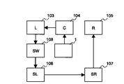
図3は、スピーカ装置の接続配置を説明する図である。図に示すように、前方中央用(Cch)スピーカ装置104、前方左用(Lch)スピーカ装置103、低音専用(SWch)スピーカ装置108、後方左用サラウンド(SLch)スピーカ装置106、後方右用サラウンド(SRch)スピーカ装置107及び前方右用(Rch)スピーカ装置105をマルチチャンネル再生装置1に対してチェーン(鎖)状に接続する。
【0016】
図4は、スピーカ装置の接続配置の他の例を説明する図である。図に示すように、前方中央用(Cch)スピーカ装置104及び低音専用(SWch)スピーカ装置108をマルチチャンネル再生装置1に対して放射状に接続し、前方中央用(Cch)スピーカ装置104及び低音専用(SWch)スピーカ装置108に対してそれぞれ前方左用(Lch)スピーカ装置103及び前方右用(Rch)スピーカ装置105、並びに後方左用サラウンド(SLch)スピーカ装置106及び後方右用サラウンド(SRch)スピーカ装置107を放射状に接続する。
【0017】
このように、マルチチャンネル識別子及び同期信号を含むマルチチャンネル出力信号を複数のスピーカ装置に出力し、一方、スピーカ装置は前記出力信号のうちの所定チャンネルのオーディオ信号のみを前記チャンネル識別子設定手段により設定した情報に基づき抽出し前記同期信号に同期して再生することにより、各スピーカ装置の接続順序にとらわれない自由な接続配置が可能となる。
【0018】
図5は、スピーカ装置に駆動用電源及びマルチチャンネル出力信号を供給する接続ケーブルを説明する図である。図に示すように接続ケーブルは2本の同軸ケーブルを例えば束ねた構成であり、一方の同軸ケーブルの芯線及び外導体で駆動用電源を供給し、他方の同軸ケーブルの芯線及び外導体でマルチチャンネル出力信号を伝送する。この電源供給方式では、接続線を従来のスピーカケーブルに近似した形状に構成できる。また、電源及び信号を一組のケーブルで伝送することができる。
【0019】
なお、各スピーカ装置が個別に電源を得ることができる場合には、光ケーブルあるいはピンケーブルを用いて前記マルチチャンネル出力信号を供給することができる。
【0020】
また、以上の説明では、本実施形態のマルチチャンネル再生装置は、スピーカ装置に同期信号を伝送することを前提に説明したが、図2に示す転送周期Tを例えば0.1秒以下に設定することにより、前記同期信号の伝送を省略することができる。すなわち、この場合は、1番目のチャンネルが割り当てられたスピーカ装置の出力タイミングと第n番目(最後)のチャンネルが割り当てられたスピーカ装置の出力タイミングには略0.1秒のずれが生じるが、この程度のずれではマルチチャンネルのオーディオ信号を聴取する者に違和感を与えることはない。
【0021】
なお、前記各スピーカ装置は、他のスピーカ装置と同期してオーディオ信号を出力するサラウンドオーディオ信号とする必要のない場合、すなわち複数のスピーカ装置にそれぞれに割り当てられたチャンネルのオーディオ信号を同時に出力させる必要がない場合(複数のスピーカがそれぞれ別々の部屋に割り当てられる場合等)は、同期信号によらず予め割り当てられたチャンネルのオーディオ信号を出力する構成とすることができる。この場合はスピーカ装置を簡易化することができ製作コストを低減することができる。
【0022】
以上説明したように、本実施形態によれば、複数のスピーカ装置を用いてマルチチャンネル再生行う際、各スピーカ装置間をチェーン状、あるいは放射状に順次接続するので、接続線の設定が煩雑化することはない。また、マルチチャンネル識別子を含むマルチチャンネル出力信号を複数のスピーカ装置に出力し、一方、スピーカ装置は前記出力信号のうちの所定チャンネルのオーディオ信号を前記チャンネル識別子設定手段により設定した情報に基づき抽出して再生するので、複数のスピーカ装置からサラウンドオーディオ信号を忠実に再生出力することができる。
【0023】
【発明の効果】
以上説明したように本発明によれば、相互間を簡易に接続することができるマルチチャンネル再生装置あるいはマルチチャンネル再生用スピーカ装置を提供することができる。
【図面の簡単な説明】
【図1】本発明の実施形態にかかるマルチチャンネル再生装置及びマルチチャンネル再生用スピーカ装置を説明する図である。
【図2】マルチチャンネル出力信号の構成を説明する図である。
【図3】スピーカ装置の接続配置を説明する図である。
【図4】スピーカ装置の接続配置の他の例を説明する図である。
【図5】スピーカ装置に駆動用電源及びマルチチャンネル出力信号を供給する接続ケーブルを説明する図である。
【図6】従来のマルチチャンネル再生装置を説明する図である。
【符号の説明】
1 マルチチャンネル再生装置
1a デジタル信号入力端子
1b アナログ信号入力端子
1c マルチチャンネル出力信号出力端子
2 再生装置
3 入力選択手段
4 A/D変換装置
5 チャンネル数設定手段
6 DSP
7 電源装置
11 デコーダ
12 メモリ
13 チャンネル識別子設定手段
14 D/A変換器
15 アンプ
16 スピーカ
20 21,22,2n マルチチャンネル再生用スピーカ装置
20a マルチチャンネル出力信号の入力端子
20b マルチチャンネル出力信号の出力端子
103 前方左用(Lch)スピーカ装置
104 前方中央用(Cch)スピーカ装置
105 前方右用(Rch)スピーカ装置
106 後方左用サラウンド(SLch)スピーカ装置
107 後方右用サラウンド(SRch)スピーカ装置[0001]
TECHNICAL FIELD OF THE INVENTION
The present invention relates to a multi-channel playback device and a multi-channel playback speaker device, and more particularly to a multi-channel playback device and a multi-channel playback speaker device that are interconnected.
[0002]
[Prior art]
FIG. 6 is a diagram illustrating a conventional multi-channel playback device. The multi-channel playback device is a
[0003]
[Problems to be solved by the invention]
When a multi-channel audio signal is reproduced using the conventional multi-channel reproduction device, all the speakers (103 to 108) must be connected to the
[0004]
The present invention has been made in view of these problems, and provides a multi-channel reproduction device or a multi-channel reproduction speaker device that can easily connect each other.
[0005]
[Means for Solving the Problems]
The present invention employs the following means in order to solve the above problems.
[0006]
A multi-channel playback device that inputs audio data, processes the input audio data by a signal processing circuit, and supplies the processed signal to a plurality of distributed speaker devices to output audio, wherein the signal processing circuit includes: Converting means for converting input audio data into a plurality of channel data; compressing the plurality of channel data converted by the converting means for each channel data; assigning a channel identifier to each of the compressed channel data; Signal processing means for generating an output signal;
[0007]
BEST MODE FOR CARRYING OUT THE INVENTION
Hereinafter, embodiments of the present invention will be described with reference to the accompanying drawings. FIG. 1 is a diagram illustrating a multi-channel playback device and a multi-channel playback speaker device according to an embodiment of the present invention. In the figure, 1 is a multi-channel playback device, 2 is a playback device such as an LD player or a DVD player, 3 is a playback output of the playback device 2, a conversion output of an A / D (Analog / Digital) converter 4, or an external digital input signal. 4 is an A / D converter for A / D converting an external analog input signal, 5 is a channel number setting means for setting the number of channels output from the multi-channel playback device 1, and 6 is A DSP (Digital Signal Processor), which receives an audio signal from the input selection means 3 and decodes the input signal, adjusts the reproduction separation, adds reverberation sound, converts the number of channels, compresses, amplifies, and outputs the synchronization signal. Various processes such as addition are performed and output as a multi-channel output signal. Reference numeral 7 denotes a power supply device that supplies power to each unit of the playback device 1 or a speaker. 1a is a digital signal input terminal, 1b is an analog signal input terminal, and 1c is a multi-channel output signal output terminal.
[0008]
20 is a speaker device for multi-channel reproduction, 11 is a decoder for extracting a channel signal set by a channel identifier setting means described later from the multi-channel output signal and decoding it, 12 is a memory for temporarily storing the output of the
[0009]
[0010]
The multi-channel playback device 1 inputs a playback audio signal from a playback device 2 built in the multi-channel playback device 1 or inputs an audio signal supplied from the outside, and inputs the input audio signal to the
[0011]
As described above, when the multi-channel reproduction device 1 reproduces a 5-channel audio signal, the multi-channel reproduction device 1 compresses each of the 5-channel signals at a compression ratio of 1/5 or more, and compresses each of the compressed signals. Multiplex and output. At this time, power for driving the speaker can be supplied from the power supply device 7 together with the compressed audio signal via a signal line connecting the multi-channel reproducing device 1 and each of the
[0012]
The speaker device 20 receives a multi-channel output signal including a multi-channel identifier, extracts an audio signal of the channel set by the channel
[0013]
The
[0014]
FIG. 2 is a diagram illustrating the configuration of a multi-channel output signal. In the figure, ch1, ch2,... Chn indicate channel identifiers, and ch1DATA, ch2DATA,... ChnDATA indicate audio signals for each channel to which channel identifiers ch1, ch2. Time DATA indicates a synchronization signal for synchronizing and outputting the audio signals of ch1DATA to chnDATA. T indicates a data transfer cycle.
[0015]
FIG. 3 is a diagram illustrating the connection arrangement of the speaker devices. As shown in the figure, the front center (Cch)
[0016]
FIG. 4 is a diagram illustrating another example of the connection arrangement of the speaker devices. As shown in the figure, a front center (Cch)
[0017]
As described above, the multi-channel output signal including the multi-channel identifier and the synchronization signal is output to the plurality of speaker devices, and the speaker device sets only the audio signal of the predetermined channel among the output signals by the channel identifier setting means. By extracting the information based on the extracted information and reproducing the information in synchronization with the synchronization signal, a free connection arrangement can be made regardless of the connection order of the speaker devices.
[0018]
FIG. 5 is a diagram illustrating a connection cable for supplying a driving power supply and a multi-channel output signal to the speaker device. As shown in the figure, the connection cable has a configuration in which two coaxial cables are bundled, for example, and a driving power is supplied by a core wire and an outer conductor of one coaxial cable, and a multi-channel is supplied by a core wire and an outer conductor of the other coaxial cable. Transmit the output signal. In this power supply system, the connection line can be configured in a shape similar to a conventional speaker cable. Also, power and signals can be transmitted over a set of cables.
[0019]
If each speaker device can individually obtain power, the multi-channel output signal can be supplied using an optical cable or a pin cable.
[0020]
In the above description, the multi-channel playback device of the present embodiment has been described on the assumption that a synchronization signal is transmitted to the speaker device. However, the transfer cycle T shown in FIG. 2 is set to, for example, 0.1 second or less. Thus, transmission of the synchronization signal can be omitted. That is, in this case, the output timing of the speaker device to which the first channel is assigned and the output timing of the speaker device to which the n-th (last) channel is assigned are shifted by about 0.1 second. With such a deviation, a person listening to the multi-channel audio signal does not feel uncomfortable.
[0021]
Each of the speaker devices does not need to be a surround audio signal that outputs an audio signal in synchronization with another speaker device, that is, simultaneously outputs audio signals of channels respectively assigned to a plurality of speaker devices. When there is no need (for example, when a plurality of speakers are assigned to different rooms), an audio signal of a channel assigned in advance can be output without depending on a synchronization signal. In this case, the speaker device can be simplified and the production cost can be reduced.
[0022]
As described above, according to the present embodiment, when performing multi-channel playback using a plurality of speaker devices, the connection between the speaker devices is sequentially performed in a chain or radial manner, so that setting of connection lines is complicated. Never. Also, a multi-channel output signal including a multi-channel identifier is output to a plurality of speaker devices, and the speaker device extracts an audio signal of a predetermined channel from the output signals based on information set by the channel identifier setting means. Therefore, surround audio signals can be faithfully reproduced and output from a plurality of speaker devices.
[0023]
【The invention's effect】
As described above, according to the present invention, it is possible to provide a multi-channel playback device or a multi-channel playback speaker device that can easily connect the devices.
[Brief description of the drawings]
FIG. 1 is a diagram illustrating a multi-channel playback device and a multi-channel playback speaker device according to an embodiment of the present invention.
FIG. 2 is a diagram illustrating a configuration of a multi-channel output signal.
FIG. 3 is a diagram illustrating a connection arrangement of a speaker device.
FIG. 4 is a diagram illustrating another example of the connection arrangement of the speaker device.
FIG. 5 is a diagram illustrating a connection cable for supplying a driving power supply and a multi-channel output signal to a speaker device.
FIG. 6 is a diagram illustrating a conventional multi-channel playback device.
[Explanation of symbols]
REFERENCE SIGNS LIST 1 multi-channel reproducing
Reference Signs List 7
Claims (7)
前記信号処理回路は、入力したオーディオデータを複数のチャンネルデータに変換する変換手段と、該変換手段により変換した前記複数のチャンネルデータを各チャンネルデータ毎に圧縮し、圧縮したチャンネルデータにそれぞれチャンネル識別子を付与してマルチチャンネル出力信号を生成する信号処理手段を備えたことを特徴とするマルチチャンネル再生装置。A multi-channel playback device that inputs audio data, processes the input audio data by a signal processing circuit, and supplies and outputs the processed signal to a plurality of speaker devices arranged in a distributed manner.
The signal processing circuit includes a conversion unit that converts input audio data into a plurality of channel data, compresses the plurality of channel data converted by the conversion unit for each channel data, and assigns a channel identifier to each of the compressed channel data. And a signal processing means for generating a multi-channel output signal by adding a signal.
前記信号処理回路は、外部または内蔵する再生手段から入力したオーディオデータを複数のチャンネルデータに変換する変換手段と、該変換手段により変換した前記複数のチャンネルデータを各チャンネルデータ毎に圧縮し、圧縮したチャンネルデータにそれぞれチャンネル識別子を付与してマルチチャンネル出力信号を生成する信号処理手段を備えたことを特徴とするマルチチャンネル再生装置。A multi-channel playback device that inputs audio data, processes the input audio data by a signal processing circuit, and supplies and outputs the processed signal to a plurality of speaker devices arranged in a distributed manner.
The signal processing circuit includes a conversion unit that converts audio data input from an external or built-in playback unit into a plurality of channel data, and compresses the plurality of channel data converted by the conversion unit for each channel data. A multi-channel reproducing apparatus comprising: a signal processing unit that generates a multi-channel output signal by assigning a channel identifier to each of the generated channel data.
前記信号処理手段は、前記圧縮したチャンネルデータ及び該データに付与するチャンネル識別子に更に同期信号を付与すると共に、これらチャンネルデータ、チャンネル識別子及び同期信号をシリアル変換してマルチチャンネル出力信号を生成することを特徴とするマルチチャンネル再生装置。In any one of claims 1 and 2,
The signal processing means further adds a synchronization signal to the compressed channel data and a channel identifier to be given to the data, and generates a multi-channel output signal by serially converting the channel data, the channel identifier and the synchronization signal. A multi-channel playback device characterized by the following.
該スピーカ装置は、前記再生するチャンネルに対応するチャンネル識別子を設定する識別子設定手段と、前記マルチチャンネル出力信号から前記識別子設定手段により設定されたチャンネル識別子に対応するチャンネルデータを抽出して再生するスピーカ駆動手段を備えたことを特徴とするマルチチャンネル再生用スピーカ装置。A multi-channel reproduction speaker device for inputting a multi-channel output signal including a plurality of channel data and a channel identifier attached to each of the channel data and outputting audio,
The speaker device includes: an identifier setting unit that sets a channel identifier corresponding to the channel to be reproduced; and a speaker that extracts and reproduces channel data corresponding to the channel identifier set by the identifier setting unit from the multi-channel output signal. A speaker device for multi-channel reproduction, comprising a driving means.
前記スピーカ装置は、前記マルチチャンネル出力信号を入力する入力端子及び入力した前記マルチチャンネル出力信号を出力する出力端子を備えたことを特徴とするマルチチャンネル再生用スピーカ装置。In the description of claim 4,
The speaker device for multi-channel reproduction, comprising: an input terminal for inputting the multi-channel output signal; and an output terminal for outputting the input multi-channel output signal.
前記マルチチャンネル再生用スピーカ装置は前記入力端子及び出力端子を介して鎖状に接続することを特徴とするマルチチャンネル再生用スピーカ装置。In the description of claim 5,
The speaker device for multi-channel reproduction is connected in a chain via the input terminal and the output terminal.
前記スピーカ装置は、前記識別子設定手段により設定されたチャンネル識別子に対応するチャンネルデータを蓄積するメモリを備え、メモリに蓄積したデータを前記マルチチャンネル出力信号に同期して出力することを特徴とするマルチチャンネル再生用スピーカ装置。In any one of claims 4 to 6,
The speaker device includes a memory for storing channel data corresponding to a channel identifier set by the identifier setting means, and outputs the data stored in the memory in synchronization with the multi-channel output signal. Channel playback speaker device.
Priority Applications (3)
| Application Number | Priority Date | Filing Date | Title |
|---|---|---|---|
| JP2002177370A JP2004023549A (en) | 2002-06-18 | 2002-06-18 | Multichannel reproducing device and loudspeaker device for multichannel reproduction |
| EP03251923A EP1377114A3 (en) | 2002-06-18 | 2003-03-26 | Multi-channel reproducing apparatus and multi-channel reproducing loudspeaker apparatus |
| US10/396,384 US20040071059A1 (en) | 2002-06-18 | 2003-03-26 | Multi-channel reproducing apparatus and multi-channel reproducing loudspeaker apparatus |
Applications Claiming Priority (1)
| Application Number | Priority Date | Filing Date | Title |
|---|---|---|---|
| JP2002177370A JP2004023549A (en) | 2002-06-18 | 2002-06-18 | Multichannel reproducing device and loudspeaker device for multichannel reproduction |
Publications (2)
| Publication Number | Publication Date |
|---|---|
| JP2004023549A true JP2004023549A (en) | 2004-01-22 |
| JP2004023549A5 JP2004023549A5 (en) | 2005-09-15 |
Family
ID=29717469
Family Applications (1)
| Application Number | Title | Priority Date | Filing Date |
|---|---|---|---|
| JP2002177370A Pending JP2004023549A (en) | 2002-06-18 | 2002-06-18 | Multichannel reproducing device and loudspeaker device for multichannel reproduction |
Country Status (3)
| Country | Link |
|---|---|
| US (1) | US20040071059A1 (en) |
| EP (1) | EP1377114A3 (en) |
| JP (1) | JP2004023549A (en) |
Cited By (1)
| Publication number | Priority date | Publication date | Assignee | Title |
|---|---|---|---|---|
| JP2008304782A (en) * | 2007-06-08 | 2008-12-18 | Yamaha Corp | Content output device and content data distribution system |
Families Citing this family (4)
| Publication number | Priority date | Publication date | Assignee | Title |
|---|---|---|---|---|
| KR100754210B1 (en) * | 2006-03-08 | 2007-09-03 | 삼성전자주식회사 | Method and apparatus for reproducing multi channel sound using cable/wireless device |
| SE531023C2 (en) * | 2007-02-08 | 2008-11-18 | Paer Gunnars Risberg | Listening System |
| FR2958106B1 (en) * | 2010-03-26 | 2012-08-31 | Finsecur | METHOD AND DEVICE FOR LOCAL SPEAKER CONTROL |
| US10621994B2 (en) * | 2014-06-06 | 2020-04-14 | Sony Corporaiton | Audio signal processing device and method, encoding device and method, and program |
Family Cites Families (9)
| Publication number | Priority date | Publication date | Assignee | Title |
|---|---|---|---|---|
| US4922536A (en) * | 1988-11-14 | 1990-05-01 | Massachusetts Institute Of Technology | Digital audio transmission for use in studio, stage or field applications |
| US5121409A (en) * | 1990-04-04 | 1992-06-09 | Artran, Inc. | Multichannel satellite communication and control system |
| US5406634A (en) * | 1993-03-16 | 1995-04-11 | Peak Audio, Inc. | Intelligent speaker unit for speaker system network |
| US5483528A (en) * | 1994-10-11 | 1996-01-09 | Telex Communications, Inc. | TDM digital matrix intercom system |
| FI97576C (en) * | 1995-03-17 | 1997-01-10 | Farm Film Oy | Listening System |
| JP3491401B2 (en) * | 1995-08-02 | 2004-01-26 | ソニー株式会社 | Data encoding device and method, and data decoding device and method |
| DE19726176C1 (en) * | 1997-06-20 | 1999-01-21 | D & B Audiotechnik Ag | Method and device for operating a sound system |
| JP2000295186A (en) * | 1999-04-02 | 2000-10-20 | Smk Corp | Method and system for voice multiplex broadcast |
| DE10052896B4 (en) * | 2000-10-25 | 2005-04-21 | D&B Audiotechnik Ag | Method for configuring a public address system and configurable public address system |
-
2002
- 2002-06-18 JP JP2002177370A patent/JP2004023549A/en active Pending
-
2003
- 2003-03-26 US US10/396,384 patent/US20040071059A1/en not_active Abandoned
- 2003-03-26 EP EP03251923A patent/EP1377114A3/en not_active Withdrawn
Cited By (1)
| Publication number | Priority date | Publication date | Assignee | Title |
|---|---|---|---|---|
| JP2008304782A (en) * | 2007-06-08 | 2008-12-18 | Yamaha Corp | Content output device and content data distribution system |
Also Published As
| Publication number | Publication date |
|---|---|
| US20040071059A1 (en) | 2004-04-15 |
| EP1377114A3 (en) | 2006-11-02 |
| EP1377114A2 (en) | 2004-01-02 |
Similar Documents
| Publication | Publication Date | Title |
|---|---|---|
| JP5316189B2 (en) | AV system | |
| KR100739723B1 (en) | Method and apparatus for audio reproduction supporting audio thumbnail function | |
| US20040037433A1 (en) | Multi-channel wireless professional audio system | |
| US8315724B2 (en) | Wireless audio streaming transport system | |
| KR102081336B1 (en) | Audio System, Audio Device and Method for Channel Mapping Thereof | |
| WO2020182020A1 (en) | Audio signal playback method and display device | |
| JP2001025085A (en) | Channel arranging device | |
| WO2021008134A1 (en) | Display device | |
| JP2001275194A (en) | Speaker system, information transmitter and speaker unit | |
| JP2009260458A (en) | Sound reproducing device and video image sound viewing/listening system containing the same | |
| KR20150115309A (en) | Potable auido apparatus for saving power and method saving power thereof | |
| JP5338053B2 (en) | Wavefront synthesis signal conversion apparatus and wavefront synthesis signal conversion method | |
| JP2004023549A (en) | Multichannel reproducing device and loudspeaker device for multichannel reproduction | |
| JP5590186B2 (en) | AV system | |
| US10028058B2 (en) | VSR surround sound tube headphone | |
| US20040213411A1 (en) | Audio data processing device, audio data processing method, its program and recording medium storing the program | |
| JP2004120407A (en) | Multichannel reproducing apparatus and multichannel reproduction speaker device | |
| KR200247762Y1 (en) | Multiple channel multimedia speaker system | |
| JP2004023549A5 (en) | ||
| KR101634387B1 (en) | Apparatus and system for reproducing multi channel audio signal | |
| JP7359896B1 (en) | Sound processing equipment and karaoke system | |
| EP4114041A1 (en) | Av amplifier | |
| EP1905035B1 (en) | Audio reproduction method and apparatus supporting audio thumbnail function | |
| CN213880236U (en) | Sound effect conversion device | |
| KR200357331Y1 (en) | Multichannel Headphone |
Legal Events
| Date | Code | Title | Description |
|---|---|---|---|
| A521 | Request for written amendment filed |
Free format text: JAPANESE INTERMEDIATE CODE: A523 Effective date: 20050323 |
|
| A621 | Written request for application examination |
Free format text: JAPANESE INTERMEDIATE CODE: A621 Effective date: 20050323 |
|
| A131 | Notification of reasons for refusal |
Free format text: JAPANESE INTERMEDIATE CODE: A131 Effective date: 20071002 |
|
| A711 | Notification of change in applicant |
Free format text: JAPANESE INTERMEDIATE CODE: A712 Effective date: 20071116 |
|
| A521 | Request for written amendment filed |
Free format text: JAPANESE INTERMEDIATE CODE: A523 Effective date: 20071128 |
|
| A131 | Notification of reasons for refusal |
Free format text: JAPANESE INTERMEDIATE CODE: A131 Effective date: 20080108 |
|
| A521 | Request for written amendment filed |
Free format text: JAPANESE INTERMEDIATE CODE: A523 Effective date: 20080304 |
|
| A131 | Notification of reasons for refusal |
Free format text: JAPANESE INTERMEDIATE CODE: A131 Effective date: 20080729 |
|
| A02 | Decision of refusal |
Free format text: JAPANESE INTERMEDIATE CODE: A02 Effective date: 20081125 |