JP2004019746A - Float type drain trap - Google Patents
Float type drain trap Download PDFInfo
- Publication number
- JP2004019746A JP2004019746A JP2002173942A JP2002173942A JP2004019746A JP 2004019746 A JP2004019746 A JP 2004019746A JP 2002173942 A JP2002173942 A JP 2002173942A JP 2002173942 A JP2002173942 A JP 2002173942A JP 2004019746 A JP2004019746 A JP 2004019746A
- Authority
- JP
- Japan
- Prior art keywords
- valve
- float
- valve port
- port
- outlet
- Prior art date
- Legal status (The legal status is an assumption and is not a legal conclusion. Google has not performed a legal analysis and makes no representation as to the accuracy of the status listed.)
- Granted
Links
Images
Abstract
Description
【0001】
【発明の属する技術分野】
本発明は、弁室内に収容したフロートの浮上降下によって弁室と出口を連通する弁口を開閉し、蒸気や圧縮空気及びガス配管系に発生する復水や凝縮水等のドレンを自動的に排出するフロート式ドレントラップに関し、特に、開口面積の大きな弁口を開閉できるフロート式ドレントラップに関する。
【0002】
【従来の技術】
開口面積の大きな弁口を開閉できる従来のフロート式ドレントラップは、例えば特開平11−82885号公報に示されている。当該公報から理解されるように、ケーシングで入口と弁室と出口を形成し、弁室と出口を連通する上下同一軸上の上弁口及び下弁口を設け、上弁口を開閉するフロートを上弁口の上方の弁室内に配置し、下弁口を開閉する弁体を下弁口の上方の出口側に配置し、フロートと弁体をねじ結合したものであり、フロートと弁体に弁室と出口の流体圧力を逆向きに作用させることによって、上弁口及び下弁口からなる開口面積の大きな弁口を開閉できるものである。
【0003】
【発明が解決しようとする課題】
上記従来のフロート式ドレントラップにおいては、フロートと弁体の結合部を高精度に加工しても、フロートと弁体を結合するときのねじ込み量やねじ込み角度のずれによって、フロートと弁体が同時に上弁口と下弁口に着座できなくなる問題点があった。
【0004】
従って、本発明の技術的課題は、フロートと弁体が同時に上弁口と下弁口に着座できるフロート式ドレントラップを提供することである。
【0005】
【課題を解決するための手段】
上記の技術的課題を解決するために講じた本発明の技術的手段は、ケーシングで入口と弁室と出口を形成し、弁室と出口を連通する上下同一軸上の上弁口及び下弁口を設け、上弁口を開閉するフロートを上弁口の上方の弁室内に配置し、下弁口を開閉する弁体を下弁口の上方の出口側に配置し、フロートの下端面と弁体の上端面を当接させたことを特徴とするフロート式ドレントラップにある。
【0006】
【発明の実施の形態】
本発明のフロート式ドレントラップは、フロートと弁体をねじ結合せず、フロートの下端面と弁体の上端面を当接させたものであるので、フロートと弁体が同時に上弁口と下弁口に着座できる。
【0007】
【実施例】
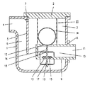
上記の技術的手段の具体例を示す実施例を説明する(図1参照)。本体1に蓋体2をボルト等の締結手段(図示せず)で固着し、内部に弁室3を有するケーシングを形成する。本体1の上部に入口4を形成し、隔壁5で仕切られた流入通路6を通して弁室3に連通せしめる。隔壁5の上端には通気孔7を開ける。
【0008】
本体1に弁座部材口8を開け、弁室3に突出する弁座部材9をボルト等の締結手段(図示せず)で固着する。弁座部材9にその内部に形成した流出通路10を通して連通する出口11を形成する。弁座部材9の上壁に上弁口12を開け、下壁に下弁口13を開ける。弁室3は上弁口12と下弁口13から流出通路10を通して出口11に連通する。下弁口13は上弁口12の下方で上弁口12と同一軸上に形成する。また、下弁口13の開口面積は上弁口12の開口面積と同一あるいは僅かに小さく形成する。
【0009】
上弁口12の上方の弁室3側に上弁口12を開閉するフロート14を配置し、下弁口13の上方の出口11側に下弁口13を開閉する弁体15を配置する。弁体15の上面に一体に上案内棒16を形成し、下面に一体に上案内棒16と同一軸上に下案内棒17を形成する。フロート14が上弁口12に着座し弁体15が下弁口13に着座した位置において、上案内棒16と下案内棒17の軸心はフロート14の球心を通り、上案内棒16の上端面はフロート14の下端面に当接する。上案内棒16は弁座部材9に固着した上支持部材18で上下方向に摺動案内し、下案内棒17は弁座部材9に固着した下支持部材19で上下方向に摺動案内する。フロート14は蓋体2と弁座部材9の間に固着した多数の連通孔を有する支持筒20で上下方向に摺動案内する。
【0010】
上記実施例の作用は下記の通りである。
図示の状態は、入口4から流入通路6を通して弁室3に流入するドレンが少なく、フロート14が降下して上弁口12に着座すると共に、フロート14の降下に伴って弁体15が押し下げられて下弁口13に着座した閉弁状態を示している。入口4から流入通路6を通して弁室3に流入するドレンにより弁室3の液面が上昇すると、液面上昇に伴ってフロート14が浮上して上弁口12から離座すると共に、フロート14の浮上に伴って弁体15が弁室3の流体圧力により持ち上げられて下弁口13から離座し、上弁口12と下弁口13を開けて弁室3のドレンを流出通路10から出口11に排出する。フロート14と弁体15に弁室3と出口11の流体圧力を逆向きに作用させることによって、上弁口12及び下弁口13からなる開口面積の大きな弁口を開閉できる。
【0011】
ドレンの排出により弁室3の液面が低下すると、液面低下に伴ってフロート14が降下して上弁口12に着座すると共に、フロート14の降下に伴って弁体15が押し下げられて下弁口13に着座した閉弁状態に戻る。
【0012】
【発明の効果】
本発明は下記の特有の効果を生じる。
上記のように本発明によるフロート式ドレントラップは、フロートと弁体をねじ結合せず、フロートの下端面と弁体の上端面を当接させたものであるので、フロートと弁体が同時に上弁口と下弁口に着座でき、蒸気や圧縮空気やガスを漏洩することがないという優れた効果を生じる。
【図面の簡単な説明】
【図1】本発明の実施例のフロート式ドレントラップの断面図である。
【符号の説明】
1 本体
2 蓋体
3 弁室
4 入口
9 弁座部材
11 出口
12 上弁口
13 下弁口
14 フロート
15 弁体[0001]
TECHNICAL FIELD OF THE INVENTION
The present invention opens and closes a valve port that connects a valve chamber and an outlet by the rising and falling of a float accommodated in a valve chamber, and automatically drains steam, compressed air, and condensed water generated in a gas piping system. More particularly, the present invention relates to a float drain trap capable of opening and closing a valve port having a large opening area.
[0002]
[Prior art]
A conventional float type drain trap capable of opening and closing a valve port having a large opening area is disclosed in, for example, Japanese Patent Application Laid-Open No. H11-82885. As understood from this publication, an inlet, a valve chamber, and an outlet are formed in a casing, and an upper valve port and a lower valve port are provided on the same axis in the upper and lower directions communicating the valve chamber and the outlet, and a float that opens and closes the upper valve port. Is disposed in the valve chamber above the upper valve port, the valve element for opening and closing the lower valve port is disposed on the outlet side above the lower valve port, and the float and the valve element are screw-connected. By causing the fluid pressures of the valve chamber and the outlet to act in opposite directions, a valve port having a large opening area including an upper valve port and a lower valve port can be opened and closed.
[0003]
[Problems to be solved by the invention]
In the above-mentioned conventional float type drain trap, even if the joint between the float and the valve body is machined with high precision, the float and the valve body are simultaneously operated due to the difference in the screwing amount and the screwing angle when connecting the float and the valve body. There was a problem that the upper and lower valve openings could not be seated.
[0004]
Therefore, a technical problem of the present invention is to provide a float type drain trap in which a float and a valve element can be simultaneously seated on an upper valve port and a lower valve port.
[0005]
[Means for Solving the Problems]
The technical means of the present invention taken in order to solve the above technical problem is to form an inlet, a valve chamber, and an outlet in a casing, and to connect the valve chamber and the outlet with an upper valve port and a lower valve on the same upper and lower axes. A port is provided, a float that opens and closes the upper valve port is disposed in the valve chamber above the upper valve port, a valve body that opens and closes the lower valve port is disposed on the outlet side above the lower valve port, and a lower end face of the float is provided. In a float type drain trap, an upper end surface of a valve body is abutted.
[0006]
BEST MODE FOR CARRYING OUT THE INVENTION
In the float type drain trap of the present invention, the float and the valve element are not screwed together, but the lower end face of the float and the upper end face of the valve element are in contact with each other. Can sit at the valve.
[0007]
【Example】
An embodiment showing a specific example of the above technical means will be described (see FIG. 1). A
[0008]
A valve
[0009]
A
[0010]
The operation of the above embodiment is as follows.
In the state shown in the figure, the drain flowing from the inlet 4 into the
[0011]
When the liquid level in the
[0012]
【The invention's effect】
The present invention has the following specific effects.
As described above, the float type drain trap according to the present invention has a structure in which the lower end surface of the float is in contact with the upper end surface of the valve body without screw-connecting the float and the valve body. The seat can be seated at the valve port and the lower valve port, and an excellent effect of preventing leakage of steam, compressed air or gas is produced.
[Brief description of the drawings]
FIG. 1 is a sectional view of a float type drain trap according to an embodiment of the present invention.
[Explanation of symbols]
DESCRIPTION OF
Claims (1)
Priority Applications (1)
| Application Number | Priority Date | Filing Date | Title |
|---|---|---|---|
| JP2002173942A JP4166513B2 (en) | 2002-06-14 | 2002-06-14 | Float type drain trap |
Applications Claiming Priority (1)
| Application Number | Priority Date | Filing Date | Title |
|---|---|---|---|
| JP2002173942A JP4166513B2 (en) | 2002-06-14 | 2002-06-14 | Float type drain trap |
Publications (2)
| Publication Number | Publication Date |
|---|---|
| JP2004019746A true JP2004019746A (en) | 2004-01-22 |
| JP4166513B2 JP4166513B2 (en) | 2008-10-15 |
Family
ID=31173036
Family Applications (1)
| Application Number | Title | Priority Date | Filing Date |
|---|---|---|---|
| JP2002173942A Expired - Fee Related JP4166513B2 (en) | 2002-06-14 | 2002-06-14 | Float type drain trap |
Country Status (1)
| Country | Link |
|---|---|
| JP (1) | JP4166513B2 (en) |
Cited By (1)
| Publication number | Priority date | Publication date | Assignee | Title |
|---|---|---|---|---|
| JP5687797B1 (en) * | 2014-09-24 | 2015-03-18 | 新倉工業株式会社 | Auto drain valve |
Families Citing this family (2)
| Publication number | Priority date | Publication date | Assignee | Title |
|---|---|---|---|---|
| KR101315034B1 (en) * | 2011-07-05 | 2013-10-04 | (주)오선텍 | Liquid separation and Auto-drain devices improving valve closing |
| KR20130056932A (en) | 2011-11-23 | 2013-05-31 | 에스케이이노베이션 주식회사 | Battery pack |
-
2002
- 2002-06-14 JP JP2002173942A patent/JP4166513B2/en not_active Expired - Fee Related
Cited By (1)
| Publication number | Priority date | Publication date | Assignee | Title |
|---|---|---|---|---|
| JP5687797B1 (en) * | 2014-09-24 | 2015-03-18 | 新倉工業株式会社 | Auto drain valve |
Also Published As
| Publication number | Publication date |
|---|---|
| JP4166513B2 (en) | 2008-10-15 |
Similar Documents
| Publication | Publication Date | Title |
|---|---|---|
| JP2004019746A (en) | Float type drain trap | |
| JP4648079B2 (en) | Exhaust valve | |
| JP2007138987A (en) | Exhaust valve | |
| JP2006316940A (en) | Exhaust valve | |
| JP2004019747A (en) | Float type drain trap | |
| JP2006316939A (en) | Exhaust valve | |
| JPH1182885A (en) | Float type drain trap | |
| JP2714889B2 (en) | Float valve | |
| JPH0637274Y2 (en) | Pilot steam trap | |
| JP2005147250A (en) | Steam trap with piping joint | |
| JP2005121085A (en) | Exhaust valve | |
| JPH082559Y2 (en) | Free float type drain trap | |
| JP2562905Y2 (en) | Pilot type steam trap | |
| JP3444566B2 (en) | Float valve | |
| JP2001050490A (en) | Float type drain trap | |
| JPS6123733Y2 (en) | ||
| JPH0663599B2 (en) | Pilot steam trap | |
| JP2000266287A (en) | Free float type drain trap | |
| JP2884293B2 (en) | Pilot type steam trap | |
| JP2714890B2 (en) | Float valve | |
| JP2802467B2 (en) | Float valve | |
| JP2005121084A (en) | Exhaust valve | |
| JPH0637273Y2 (en) | Pilot steam trap | |
| JP2745276B2 (en) | Float valve | |
| JPH10227397A (en) | Float type drain trap |
Legal Events
| Date | Code | Title | Description |
|---|---|---|---|
| A621 | Written request for application examination |
Free format text: JAPANESE INTERMEDIATE CODE: A621 Effective date: 20050519 |
|
| A977 | Report on retrieval |
Free format text: JAPANESE INTERMEDIATE CODE: A971007 Effective date: 20080326 |
|
| A131 | Notification of reasons for refusal |
Free format text: JAPANESE INTERMEDIATE CODE: A131 Effective date: 20080401 |
|
| A521 | Written amendment |
Free format text: JAPANESE INTERMEDIATE CODE: A523 Effective date: 20080523 |
|
| TRDD | Decision of grant or rejection written | ||
| A01 | Written decision to grant a patent or to grant a registration (utility model) |
Free format text: JAPANESE INTERMEDIATE CODE: A01 Effective date: 20080729 |
|
| A01 | Written decision to grant a patent or to grant a registration (utility model) |
Free format text: JAPANESE INTERMEDIATE CODE: A01 |
|
| A61 | First payment of annual fees (during grant procedure) |
Free format text: JAPANESE INTERMEDIATE CODE: A61 Effective date: 20080730 |
|
| R150 | Certificate of patent or registration of utility model |
Free format text: JAPANESE INTERMEDIATE CODE: R150 |
|
| FPAY | Renewal fee payment (event date is renewal date of database) |
Free format text: PAYMENT UNTIL: 20110808 Year of fee payment: 3 |
|
| FPAY | Renewal fee payment (event date is renewal date of database) |
Free format text: PAYMENT UNTIL: 20120808 Year of fee payment: 4 |
|
| FPAY | Renewal fee payment (event date is renewal date of database) |
Free format text: PAYMENT UNTIL: 20130808 Year of fee payment: 5 |
|
| R250 | Receipt of annual fees |
Free format text: JAPANESE INTERMEDIATE CODE: R250 |
|
| R250 | Receipt of annual fees |
Free format text: JAPANESE INTERMEDIATE CODE: R250 |
|
| LAPS | Cancellation because of no payment of annual fees |