JP2004018131A - Paste applying cutter - Google Patents
Paste applying cutter Download PDFInfo
- Publication number
- JP2004018131A JP2004018131A JP2002171494A JP2002171494A JP2004018131A JP 2004018131 A JP2004018131 A JP 2004018131A JP 2002171494 A JP2002171494 A JP 2002171494A JP 2002171494 A JP2002171494 A JP 2002171494A JP 2004018131 A JP2004018131 A JP 2004018131A
- Authority
- JP
- Japan
- Prior art keywords
- glue
- cutter
- body case
- tape
- main body
- Prior art date
- Legal status (The legal status is an assumption and is not a legal conclusion. Google has not performed a legal analysis and makes no representation as to the accuracy of the status listed.)
- Granted
Links
Images


Abstract
Description
【0001】
【発明の属する技術分野】
本発明は、紙等のカットと、カットした紙等への糊の塗布とを行う糊塗布付きカッターに関する。
【0002】
【従来の技術】
紙を所定の形状にカットし、このカットした紙の縁に糊を塗布して紙を糊付けする作業は、良く行われる。そして、従来では、紙のカットは折刃式ナイフ(カッターナイフ)やハサミなどを用い、糊の塗布はスティック糊やテープ式糊などを用いて行っている。
【0003】
【発明が解決しようとする課題】
従って、紙をカットし、カットした紙に糊付けするのに2種類の道具を用いなければならなず、一連の作業が煩雑であるという問題がある。
【0004】
そこで、本発明は、前記した課題を解決すべくなされたものであり、紙等のカットとカットした紙などへの糊付けとを同時に行うことができる糊塗布付きカッターを提供することを目的とする。
【0005】
【課題を解決するための手段】
請求項1の発明は、本体ケースと、この本体ケースより突出された刃部と、前記本体ケースより先端が突設され、前記刃部の切断方向に沿って糊を連続的に塗布できる糊塗布部とが設けられたことを特徴とする。
【0006】
この糊塗布付きカッターでは、紙等の所定位置に刃部を当て、刃部で紙等をカットしつつ、糊塗布部が刃部の切断方向に沿って糊を連続的に塗布することができる。
【0007】
請求項2の発明は、請求項1記載の糊塗布付きカッターであって、前記糊塗布部が、前記本体ケース内に収納可能に設けられていることを特徴とする。
【0008】
この糊塗布付きカッターでは、請求項1の発明の作用に加え、糊塗布部を本体ケース内に収納すれば、紙等のカットのみを行うことができる。
【0009】
請求項3の発明は、請求項1又は請求項2記載の糊塗布付きカッターであって、前記刃部が、前記本体ケース内に収納可能に設けられていることを特徴とする。
【0010】
この糊塗布付きカッターでは、請求項1又は請求項2の発明の作用に加え、刃部を本体ケース内に収納すれば、紙等への糊付けのみを行うことができる。
【0011】
請求項4の発明は、請求項1〜請求項3記載の糊塗布付きカッターであって、前記糊塗布部は、糊が塗布されたテープが連続的に供給されるテープ供給経路の一部によって構成され、このテープ供給経路の上流に糊が塗布されたテープを巻き付けた供給ローラと、テープ供給経路の下流にテープを巻き取る巻取ローラとがそれぞれ配設されていることを特徴とする。
【0012】
この糊塗布付きカッターでは、請求項1〜請求項3の発明の作用に加え、刃部の移動と共に糊付きテープが糊塗布部に順次供給され、テープに付着された糊が紙等に転移することにより、所定の位置に、且つ均一に糊を塗布することができる。
【0013】
【発明の実施の形態】
以下、本発明の一実施形態を図面に基づいて説明する。
【0014】
図1〜図4は本発明の一実施形態を示し、図1は刃部及び糊塗布部が共に収納状態である糊塗布付きカッターの構成図、図2(a)は刃部及び糊塗布部が共に突出状態である糊塗布付きカッターの構成図、図2(b)はその要部正面図、図3(a)は刃部のみが突出状態である糊塗布付きカッターの構成図、図3(b)はその要部正面図、図4(a)は糊塗布部のみが突出状態である糊塗布付きカッターの構成図、図4(b)はその要部正面図である。
【0015】
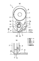
図1及び図2(a)に示すように、糊塗布付きカッター1は、ユーザが片手で握持できる本体ケース2を有し、この本体ケース2内に刃部3が配置されている。刃部3は、その先端部分をも含めて本体ケース2内に収納される収納位置(図1の位置)と、その先端部分が本体ケース2外に突出される突出位置(図2の位置)との間でスライド自在に設けられ、本体ケース2の外部に配置された第1スライドレバー4によってスライド操作できるようになっている。
【0016】
又、本体ケース2内にはスライド部材(図示せず)が配置され、このスライド部材には供給ローラ6が固定された第1ギア7と、巻取ローラ8が固定された第2ギア9と、第1ギア7と第2ギア9に共に噛み合う中間ギア10とが回転自在に支持されている。供給ローラ6には一方の面に糊が塗布されたテープ11が巻き付けられており、このテープ11はスライド部材に支持されたガイドピン12a,12bにガイドされることによって所定のテープ供給経路を通った後に巻取ローラ8に巻き取られている。このように構成されたテープ供給経路で、且つ、ガイドピン12bによって本体ケース2より突出された部分が糊塗布部13として構成されている。この糊塗布部13は、テープ供給経路の上流に糊付きテープ11を巻き付けた供給ローラ6を、テープ供給経路の下流にテープ11を巻き取る巻取ローラ8をそれぞれ有することから、糊付きテープ11が刃部3から所定距離の位置に連続的に糊を供給するようになっている。つまり、突出状態の糊塗布部13が紙等に接触された状態にあって、本体ケース2が移動されると、糊塗布部13のテープ11が紙等に糊を転写しつつ移動し、この移動力によって供給ローラ6が回転してテープ11が送り出されると共に、この第1ギア7の回転によって中間ギア10、第2ギア9が順に回転し、第2ギア9の回転で巻取ローラ8がテープ11を巻き取ることによって糊塗布部13には糊付きテープ11が連続的に供給される。
【0017】
又、スライド部材(図示せず)は本体ケース2の外部に配置された第2スライドレバー14によってスライド操作できるようになっており、このスライド操作によって糊塗布部13が本体ケース2内に収納される収納位置(図1の位置)と、本体ケース2外に突出される突出位置(図2の位置)との間で変移される。
【0018】
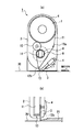
次に、糊塗布付きカッター1の作用を説明する。図1に示すように、刃部3及び糊塗布部13が共に収納位置にある場合には、図2(a)に示すように、第1及び第2スライドレバー4,14を矢印方向に操作して刃部3及び糊塗布部13を共に突出位置に位置させる。そして、図2(b)に示すように、紙20のカットしたい位置に沿って定規21を載置し、この定規21に刃部3を当てて定規21に沿って刃部3を進行方向に移動させる。すると、刃部3で紙20がカットされると共に、テープ11がa矢印方向に移動することによって糊塗布部13が刃部3の切断方向に沿って糊を連続的に塗布する。従って、紙20のカットとカットした紙20への糊付けとを同時に行うことができる。
【0019】
又、紙20のカットのみを行う場合には、図3(a)に示すように、糊塗布部13を収納位置に、刃部3を突出位置に位置させる。そして、図3(b)に示すように、紙20のカットしたい位置に沿って定規21を載置し、この定規21に刃部3を当てて定規21に沿って刃部3を移動させる。すると、刃部3で紙20がカットされる。
【0020】
次に、紙20に糊付けのみを行う場合には、図4(a)に示すように、刃部3を収納位置に、糊塗布部13を突出位置に位置させる。そして、図4(b)に示すように、糊を塗布したい紙20の位置に沿って糊塗布部13を移動させる。すると、糊塗布部13が糊を連続的に塗布する。
【0021】
以上、この糊塗布付きカッター1では、紙20等の所定位置に刃部3を当て、刃部3で紙20等をカットすると、糊塗布部13が刃部3の切断方向に沿って糊を連続的に塗布するため、紙20等のカットとカットした紙20などへの糊付けとを同時に行うことができる。
【0022】
又、この実施形態の糊塗布付きカッター1では、糊塗布部13を本体ケース2内に収納し、刃部3を突出位置とすれば、紙20等のカットのみを行うことができる。つまり、糊塗布付きカッター1をカッターとして使用できる。
【0023】
又、この実施形態の糊塗布付きカッター1では、刃部3を本体ケース2内に収納し、糊塗布部13を突出位置とすれば、紙20等への糊付けのみを行うことができる。つまり、糊塗布付けカッター1を糊塗布文具として使用できる。
【0024】
更に、この実施形態の糊塗布付きカッター1では、刃部3の移動と共に糊付きテープ11が糊塗布部13に順次供給され、テープ11に付着された糊が紙20等に転移することによって塗布されるため、カットした紙20等の所定位置に、糊がはみ出すことなく、且つ、均一に塗布できる。
【0025】
【発明の効果】
以上説明したように、請求項1の発明によれば、本体ケースと、この本体ケースより突出された刃部と、前記本体ケースより先端が突設された糊塗布部とが設けられているので、紙等の所定位置に刃部を当て、刃部で紙等をカットすると、糊塗布部が刃部の切断方向に沿って糊を連続的に塗布するため、紙等のカットとカットした紙などへの糊付けとを同時に行うことができる。
【0026】
請求項2の発明によれば、請求項1記載の糊塗布付きカッターであって、糊塗布部が、本体ケース内に収納可能に設けられているので、請求項1の発明の効果に加え、糊塗布部を本体ケース内に収納すれば、紙等のカットのみを行うことができる。つまり、糊塗布付きカッターをカッターとして使用できる。
【0027】
請求項3の発明によれば、請求項1又は請求項2記載の糊塗布付きカッターであって、刃部が、本体ケース内に収納可能に設けられているので、請求項1又は請求項2の発明の効果に加え、刃部を本体ケース内に収納すれば、紙等への糊付けのみを行うことができる。つまり、糊塗布付けカッターを糊塗布文具として使用できる。
【0028】
請求項4の発明によれば、請求項1〜請求項3記載の糊塗布付きカッターであって、糊塗布部は、糊が塗布されたテープが連続的に供給されるテープ供給経路の一部によって構成され、このテープ供給経路の上流に糊が塗布されたテープを巻き付けた供給ローラと、テープ供給経路の下流にテープを巻き取る巻取ローラとがそれぞれ配設されているので、請求項1〜請求項3の発明の効果に加え、刃部の移動と共に糊付きテープが糊塗布部に順次供給され、テープに付着された糊が紙等に転移することによって塗布されるため、カットした紙等の所定位置に、糊がはみ出すことなく、且つ、均一に塗布できる。
【図面の簡単な説明】
【図1】本発明の一実施形態を示し、刃部及び糊塗布部が共に収納状態である糊塗布付きカッターの構成図である。
【図2】本発明の一実施形態を示し、(a)は刃部及び糊塗布部が共に突出状態である糊塗布付きカッターの構成図、(b)はその要部正面図である。
【図3】本発明の一実施形態を示し、(a)は刃部のみが突出状態である糊塗布付きカッターの構成図、(b)はその要部正面図である。
【図4】本発明の一実施形態を示し、(a)は糊塗布部のみが突出状態である糊塗布付きカッターの構成図、(b)はその要部正面図である。
【符号の説明】
1 糊塗布付きカッター
2 本体ケース
3 刃部
6 供給ローラ
8 巻取ローラ
11 テープ
13 糊塗布部[0001]
TECHNICAL FIELD OF THE INVENTION
The present invention relates to a cutter with glue application for cutting paper or the like and applying glue to the cut paper or the like.
[0002]
[Prior art]
2. Description of the Related Art An operation of cutting paper into a predetermined shape, applying glue to the edge of the cut paper, and gluing the paper is often performed. Conventionally, paper is cut using a folding blade knife (cutter knife) or scissors, and glue is applied using stick glue or tape glue.
[0003]
[Problems to be solved by the invention]
Therefore, two types of tools must be used to cut the paper and glue the cut paper, and there is a problem that a series of operations is complicated.
[0004]
Therefore, the present invention has been made to solve the above-described problem, and an object of the present invention is to provide a cutter with glue application that can simultaneously cut paper and the like and glue the cut paper and the like. .
[0005]
[Means for Solving the Problems]
According to the first aspect of the present invention, there is provided a main body case, a blade portion protruding from the main body case, and a glue coating that has a tip end protruding from the main body case and can continuously apply glue along a cutting direction of the blade portion. And a section are provided.
[0006]
In the cutter with the glue application, the glue application unit can continuously apply the glue along the cutting direction of the blade unit while the blade unit is applied to a predetermined position of the paper or the like and the paper unit or the like is cut by the blade unit. .
[0007]
According to a second aspect of the present invention, there is provided the cutter with glue application according to the first aspect, wherein the glue application section is provided so as to be housed in the main body case.
[0008]
In this cutter with glue application, in addition to the operation of the invention of claim 1, if the glue application section is stored in the main body case, only cutting of paper or the like can be performed.
[0009]
According to a third aspect of the present invention, there is provided the glue-coated cutter according to the first or second aspect, wherein the blade portion is provided so as to be housed in the main body case.
[0010]
In this cutter with glue application, in addition to the function of the first or second aspect of the present invention, if the blade portion is stored in the main body case, only gluing to paper or the like can be performed.
[0011]
According to a fourth aspect of the present invention, there is provided the cutter with glue application according to any one of the first to third aspects, wherein the glue application unit is provided by a part of a tape supply path to which the tape on which the glue is applied is continuously supplied. A supply roller configured to wind a tape coated with glue upstream of the tape supply path and a take-up roller configured to wind the tape downstream of the tape supply path are provided.
[0012]
In this cutter with glue application, in addition to the effects of the invention of claims 1 to 3, tape with glue is sequentially supplied to the glue application unit with the movement of the blade portion, and the glue attached to the tape is transferred to paper or the like. Thereby, the paste can be uniformly applied to a predetermined position.
[0013]
BEST MODE FOR CARRYING OUT THE INVENTION
Hereinafter, an embodiment of the present invention will be described with reference to the drawings.
[0014]
1 to 4 show an embodiment of the present invention. FIG. 1 is a configuration diagram of a cutter with glue application in which both a blade portion and a glue application portion are housed, and FIG. 2A is a blade portion and a glue application portion. 2B is a front view of a main part of the cutter with glue coating, and FIG. 3A is a configuration diagram of a cutter with glue coating with only the blade portion protruding. 4B is a front view of a main part of the cutter, FIG. 4A is a configuration diagram of a glue-applied cutter in which only the glue application part is in a protruding state, and FIG. 4B is a front view of the main part thereof.
[0015]
As shown in FIGS. 1 and 2A, the glue-applied cutter 1 has a
[0016]
A slide member (not shown) is disposed in the
[0017]
Further, a slide member (not shown) can be slid by a
[0018]
Next, the operation of the cutter 1 with glue application will be described. As shown in FIG. 1, when both the
[0019]
When only the
[0020]
Next, when only gluing is performed on the
[0021]
As described above, in the glue-coated cutter 1, when the
[0022]
Further, in the cutter 1 with glue application of this embodiment, if the
[0023]
Further, in the cutter 1 with glue application of this embodiment, if the
[0024]
Further, in the cutter 1 with glue application of this embodiment, the glued
[0025]
【The invention's effect】
As described above, according to the first aspect of the present invention, the main body case, the blade portion protruding from the main body case, and the glue application portion having the tip protruding from the main body case are provided. When the blade portion is applied to a predetermined position of paper or the like and the paper is cut by the blade portion, the glue application portion continuously applies the glue along the cutting direction of the blade portion. Can be performed simultaneously.
[0026]
According to the invention of
[0027]
According to the third aspect of the present invention, in the glue-coated cutter according to the first or second aspect, the blade portion is provided so as to be housed in the main body case. In addition to the effects of the invention described above, if the blade portion is housed in the main body case, only gluing to paper or the like can be performed. That is, the glue application cutter can be used as a glue application stationery.
[0028]
According to a fourth aspect of the present invention, in the glue-coated cutter according to any one of the first to third aspects, the glue applying unit is a part of a tape supply path to which the tape on which the glue is applied is continuously supplied. And a winding roller for winding the tape downstream of the tape supply path and a winding roller for winding the tape downstream of the tape supply path. In addition to the effects of the invention of
[Brief description of the drawings]
FIG. 1 shows an embodiment of the present invention and is a configuration diagram of a cutter with glue application in which a blade portion and a glue application portion are both housed.
2A and 2B show an embodiment of the present invention, wherein FIG. 2A is a configuration diagram of a cutter with glue application in which both a blade portion and a glue application portion are in a protruding state, and FIG. 2B is a front view of a main part thereof.
3A and 3B show an embodiment of the present invention, wherein FIG. 3A is a configuration diagram of a glue-coated cutter in which only a blade portion is in a protruding state, and FIG.
4A and 4B show an embodiment of the present invention, wherein FIG. 4A is a configuration diagram of a glue-applied cutter in which only a glue application portion is in a protruding state, and FIG.
[Explanation of symbols]
DESCRIPTION OF SYMBOLS 1 Cutter with
Claims (4)
前記糊塗布部が、前記本体ケース内に収納可能に配設されたことを特徴とする糊塗布付きカッター。The glue-coated cutter according to claim 1,
The cutter with glue application, wherein the glue application unit is disposed so as to be housed in the main body case.
前記刃部が、前記本体ケース内に収納可能に配設されていることを特徴とする糊塗布付きカッター。The glue-coated cutter according to claim 1 or 2,
The cutter with glue coating, wherein the blade portion is disposed so as to be housed in the main body case.
前記糊塗布部は、糊が塗布されたテープが連続的に供給されるテープ供給経路の一部によって構成され、このテープ供給経路の上流に糊が塗布されたテープを巻き付けた供給ローラと、テープ供給経路の下流にテープを巻き取る巻取ローラとがそれぞれ配設されていることを特徴とする糊塗布付きカッター。A glue-coated cutter according to claim 1, wherein
The glue application unit is constituted by a part of a tape supply path to which a tape to which the adhesive is applied is continuously supplied, and a supply roller having a tape coated with the adhesive wound upstream of the tape supply path; A cutter with a glue coating, wherein a winding roller for winding the tape is disposed downstream of the supply path.
Priority Applications (1)
| Application Number | Priority Date | Filing Date | Title |
|---|---|---|---|
| JP2002171494A JP3977691B2 (en) | 2002-06-12 | 2002-06-12 | Cutter with glue application |
Applications Claiming Priority (1)
| Application Number | Priority Date | Filing Date | Title |
|---|---|---|---|
| JP2002171494A JP3977691B2 (en) | 2002-06-12 | 2002-06-12 | Cutter with glue application |
Publications (2)
| Publication Number | Publication Date |
|---|---|
| JP2004018131A true JP2004018131A (en) | 2004-01-22 |
| JP3977691B2 JP3977691B2 (en) | 2007-09-19 |
Family
ID=31171344
Family Applications (1)
| Application Number | Title | Priority Date | Filing Date |
|---|---|---|---|
| JP2002171494A Expired - Lifetime JP3977691B2 (en) | 2002-06-12 | 2002-06-12 | Cutter with glue application |
Country Status (1)
| Country | Link |
|---|---|
| JP (1) | JP3977691B2 (en) |
Cited By (1)
| Publication number | Priority date | Publication date | Assignee | Title |
|---|---|---|---|---|
| JP2017202566A (en) * | 2016-05-09 | 2017-11-16 | プラス株式会社 | Paint film transfer tool |
-
2002
- 2002-06-12 JP JP2002171494A patent/JP3977691B2/en not_active Expired - Lifetime
Cited By (3)
| Publication number | Priority date | Publication date | Assignee | Title |
|---|---|---|---|---|
| JP2017202566A (en) * | 2016-05-09 | 2017-11-16 | プラス株式会社 | Paint film transfer tool |
| KR20170126396A (en) * | 2016-05-09 | 2017-11-17 | 프러스 가부시키가이샤 | Coating film transferrer |
| KR102330518B1 (en) * | 2016-05-09 | 2021-11-24 | 프러스 가부시키가이샤 | Coating film transferrer |
Also Published As
| Publication number | Publication date |
|---|---|
| JP3977691B2 (en) | 2007-09-19 |
Similar Documents
| Publication | Publication Date | Title |
|---|---|---|
| TWI629229B (en) | Applicators for adhesive tape, such as double-sided adhesive tape | |
| JP2009535532A (en) | Applicator and method for attaching sheet material to a substrate | |
| WO2011080977A1 (en) | Tape delivery device and tape applicator | |
| JP2017522863A (en) | Chipping paper supply device used for manufacturing smoking products | |
| JP2010535678A (en) | Tape dispenser, taping method, and injection mechanism | |
| JP5210240B2 (en) | Double-sided adhesive tape application device | |
| JP4885414B2 (en) | Gripping tools for attaching films to substrates, such as adhesives, coating materials, and coloring materials | |
| JPH07252010A (en) | Tape cutter | |
| US20060113043A1 (en) | Adhesive binding tape cutter | |
| JP2007037956A (en) | Cutter knife | |
| JP2004018131A (en) | Paste applying cutter | |
| US6712113B1 (en) | Automatic device for dispensing and applying adhesive tape in rolls | |
| JP2003523859A (en) | Hand-held device with movably mounted applicator for transferring film from base tape to substrate | |
| JP2004504996A (en) | Dispenser with cutting blade / feed roll separation assembly | |
| JP2006347075A (en) | Coating film transfer implement | |
| JP2003523857A (en) | Applying the entire tape | |
| US20090272497A1 (en) | Taping Apparatus | |
| JPH06305628A (en) | Tape sticking machine | |
| JP2009132132A (en) | Paint film transfer with half-floating head | |
| JP3080598B2 (en) | Holder with cutter for masking film roll | |
| JP5963714B2 (en) | Web cutting equipment | |
| JP2007276952A (en) | Tape cutter device | |
| JP2006062777A (en) | Method and device for sticking tape on corrugated paper | |
| JP5963713B2 (en) | Web cutting equipment | |
| KR101434467B1 (en) | Apparatus For Attaching Tape |
Legal Events
| Date | Code | Title | Description |
|---|---|---|---|
| A621 | Written request for application examination |
Effective date: 20050425 Free format text: JAPANESE INTERMEDIATE CODE: A621 |
|
| A977 | Report on retrieval |
Effective date: 20070228 Free format text: JAPANESE INTERMEDIATE CODE: A971007 |
|
| A131 | Notification of reasons for refusal |
Free format text: JAPANESE INTERMEDIATE CODE: A131 Effective date: 20070313 |
|
| A521 | Written amendment |
Free format text: JAPANESE INTERMEDIATE CODE: A523 Effective date: 20070508 |
|
| TRDD | Decision of grant or rejection written | ||
| A01 | Written decision to grant a patent or to grant a registration (utility model) |
Free format text: JAPANESE INTERMEDIATE CODE: A01 Effective date: 20070605 |
|
| A61 | First payment of annual fees (during grant procedure) |
Free format text: JAPANESE INTERMEDIATE CODE: A61 Effective date: 20070621 |
|
| FPAY | Renewal fee payment (prs date is renewal date of database) |
Year of fee payment: 3 Free format text: PAYMENT UNTIL: 20100629 |
|
| R150 | Certificate of patent (=grant) or registration of utility model |
Free format text: JAPANESE INTERMEDIATE CODE: R150 |