JP2004018004A - Lidded folding container - Google Patents
Lidded folding container Download PDFInfo
- Publication number
- JP2004018004A JP2004018004A JP2002173948A JP2002173948A JP2004018004A JP 2004018004 A JP2004018004 A JP 2004018004A JP 2002173948 A JP2002173948 A JP 2002173948A JP 2002173948 A JP2002173948 A JP 2002173948A JP 2004018004 A JP2004018004 A JP 2004018004A
- Authority
- JP
- Japan
- Prior art keywords
- lid
- side wall
- long side
- folding container
- frame
- Prior art date
- Legal status (The legal status is an assumption and is not a legal conclusion. Google has not performed a legal analysis and makes no representation as to the accuracy of the status listed.)
- Granted
Links
Images


Landscapes
- Stackable Containers (AREA)
- Rigid Containers With Two Or More Constituent Elements (AREA)
Abstract
Description
【0001】
【発明の属する技術分野】
本発明は、底部にヒンジ連結された側壁が、底部に重なるようにように折り畳むことができるとともに、一方の相対する側壁に、蓋が配設されている蓋付き折り畳みコンテナーに関するものである。
【0002】
【従来の技術】
従来、折り畳みコンテナー本体を構成する相対する側壁の上端部に、蓋部材を構成する半蓋をヒンジ連結した蓋付き折り畳みコンテナーが知られている(例えば、特表平8−510981号公報)が知られている。
【0003】
【発明が解決しようとする課題】
上述した従来の蓋付き折り畳みコンテナーを、箱型に組み立てられた状態或いは折り畳まれた状態において段積みした際に、下に位置する折り畳みコンテナーの蓋部材に載置された上に位置する折り畳みコンテナーが、水平方向に移動した場合には、下に位置する折り畳みコンテナーの蓋部材には、上に位置する折り畳みコンテナーの水平方向移動を制限する阻止部材は配設されていないので、上に位置する折り畳みコンテナーが、下に位置する折り畳みコンテナーからずれて、安定した状態に段積みすることができないという問題があった。しかも、上に位置する折り畳みコンテナーが、下に位置する折り畳みコンテナーから落下するという問題もあった。
【0004】
本発明の目的は、上述した従来の蓋付き折り畳みコンテナーが有する課題を解決することにある。
【0005】
【課題を解決するための手段】
本発明は、上述した目的を達成するために、底部と底部にヒンジ連結された側壁と相対する側壁の上端部にヒンジ連結された蓋部材とを有する蓋付き折り畳みコンテナーにおいて、箱型に組み立てられ、且つ、蓋部材により被蓋された折り畳みコンテナーが、段積みされた状態において、上に位置する折り畳みコンテナーの水平移動が、下に位置する蓋部材に配設された移動阻止部材により、その水平移動が制限されるとともに、折り畳まれ、且つ、蓋部材が載置された折り畳みコンテナーを、段積みした状態においても、上に位置する折り畳まれた折り畳みコンテナーの水平移動が、下に位置する蓋部材に配設された移動阻止部材により、その水平移動が制限されるように構成したものである。
【0006】
【実施例】
以下に、本発明の実施例について説明するが、本発明の趣旨を越えない限り何ら、本実施例に限定されるものではない。
【0007】
先ず最初に、図1〜図5を用いて、蓋付き折り畳みコンテナーの全体構成、折り畳み順序及び組み立て順序について説明する。
【0008】
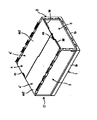
蓋付き折り畳みコンテナー(以下、単に、折り畳みコンテナーともいう。)は、底部1と底部1の相対する長辺側土手部1aにヒンジ連結された長側壁2と底部1の相対する短辺側土手部1bにヒンジ連結された短側壁3とからなる折り畳みコンテナー本体C1と、折り畳みコンテナー本体C1を構成する長側壁2の上端部にヒンジ連結された2つの半蓋4’からなる蓋部材4とから構成されている。
【0009】
図1に示されているように、蓋部材4により被蓋され、箱型に組み立てられている折り畳みコンテナーを折り畳むには、先ず最初に、蓋部材4を構成する半蓋4’を、水平状態から、略270度回転させて、図2に示されているように、長側壁2に重ねる。次いで、短側壁3を、底部1方向に倒して、図3に示されているように、底部1に重ねる。その後、半蓋4’が重ねられている長側壁2を、底部1方向に倒して、底部1に重ねられている短側壁3の上に重ねることにより、図4に示されているように、箱型に組み立てられていた折り畳みコンテナーを、高さの低いコンパクトな状態に折り畳むが、この状態においては、長側壁2に重ねられている半蓋4’の底部1の長辺側土手部1a側の縁部が、図4に示されているように、底部1の長辺側土手部1aから、外側にはみ出しているので、後述する構成により、長側壁2に重ねられ、底部1の長辺側土手部1aからはみ出している半蓋4’を、互いに接近する方向に移動させて、図5に示されているように、半蓋4’の長辺側土手部1a側の縁部が、底部1の長辺側土手部1aからはみ出さないようにすることにより、よりコンパクトに折り畳むことができるように構成されている。
【0010】
図5に示されている折り畳まれた状態から、図1に示されているように、箱型に組み立てるには、上述した折り畳み順序と反対の順序で、組み立て作業を行えばよい。即ち、図5に示されている状態から、長側壁2に重ねられている半蓋4’を、互いに離反する方向に移動させて、図4に示されているように、半蓋4’同士が離反した状態にする。次いで、略水平状態の長側壁2を、垂直方向に回動させて、図3に示されているように、略垂直に立てる。次いで、底部1に重ねられている短側壁3を、垂直方向に回動させて、図2に示されているように、折り畳まれていた折り畳みコンテナー本体C1を、箱型に組み立てる。その後、図1に示されているように、長側壁2に重ねられている半蓋4’を回動させて、図1に示されているように、折り畳みコンテナー本体C1の開口部を、蓋部材4を構成する半蓋4’で被蓋する。
【0011】
次に、図6及び図7を用いて、底部1について説明する。
【0012】
上述したように、底部1の相対する長辺には、長辺側土手部1aが形成されており、また、底部1の相対する短辺には、上記の長辺側土手部1aより高さの低い短辺側土手部1bが形成されている。そして、長辺側土手部1a及び短辺側土手部1bには、底部側雌ヒンジ部材H1が形成されている。実施例には、一例として、短辺側土手部1bに、それぞれ、4個の底部側雌ヒンジ部材H1が形成され、長辺側土手部1aに、それぞれ、6個の底部側雌ヒンジ部材H1が形成されている例が示されている。また、底部1の裏面には、長辺側土手部1aの下端1a1及び短辺側土手部1bの下端1b1を越えて下方に位置する裏面形状が方形状の嵌合膨出部1cが形成されている。
【0013】
次に、図8及び図9を用いて、長側壁2について説明する。
【0014】
長側壁2は、横長の長方形状の板部2aと、板部2aの周縁から、板部2aを囲むように、板部2aに対して略垂直に延在する周縁枠部2bを有している。周縁枠部2bの下端水平枠2b1の下面には、底部1の長辺側土手部1aに配設された底部側雌ヒンジ部材H1に対応して、長側壁側下部雄ヒンジ部材H2が配設されている。
【0015】
2cは、周縁枠部2bが配設されていない板部2aの垂直縁付近に配設された雌ブロックであり、雌ブロック2cには、板部2aに沿って、その開口が板部2aの中央側に位置する凹部2c1が形成されている。なお、本実施例には、一例として、このような雌ブロック2cが、板部2aの両側の垂直縁付近に、それぞれ、上下方向に2個ずつ配設されている例が示されている。
【0016】
長側壁2の周縁枠部2bを構成する上端水平枠2b2の上面には、長側壁側上部雄ヒンジ部材H3が配設されている。長側壁側上部雄ヒンジ部材H3は、上端水平枠2b2に略垂直に立設された相対する一対の支持片h1と、一対の支持片h1に架橋された水平ピンh2とから構成されている。なお、本実施例には、一例として、5個の長側壁側上部雄ヒンジ部材H3が配設されている例が示されている。
【0017】
次に、図10及び図11を用いて、短側壁3について説明する。
【0018】
短側壁3は、横長の長方形状の板部3aを有している。板部3aの下端には、板部3aに対して略垂直な下端水平枠3bが形成されており、また、板部3aの両垂直縁の若干内側には、その下端が、下端水平枠3bの両端に連結された、相対する端部垂直枠3cが形成されている。更に、板部3aの上端から若干下がった位置で、且つ、板部3aの上端部の両側領域には、その端部が、端部垂直枠3cの上端に連結された上部水平枠3dが形成されているとともに、板部3aの上端の中央領域には、略中央位置に凹部3e1を有する上端水平枠3eが形成されており、上端水平枠3eの両端と上部水平枠3dの端部とは、垂直枠3fで連結されている。なお、3gは、上端水平枠3eに穿設された、後述するロック部材が挿入可能な長方形状の透孔である。
【0019】
また、短側壁3に形成された下端水平枠3bの下面には、底部1の短辺側土手部1bに配設された底部側雌ヒンジ部材H1に対応して、上述した長側壁側下部雄ヒンジ部材H2と同じ構成を有する短側壁側下部雄ヒンジ部材H2が配設されている。
【0020】
更に、短側壁3に形成された端部垂直枠3cの外側に位置する板部3aの帯状領域3a1には、端部垂直枠3cに沿って、板部3aに略垂直に延在する雄ブロック3hが突設されている。なお、本実施例には、一例として、このような雄ブロック3hが、帯状領域3a1の上下方向に、それぞれ、2個ずつ配設されている例が示されている。この雄ブロック3hは、折り畳みコンテナー本体C1を箱型に組みたてた際に、上述した長側壁2に配設された雌ブロック2cの凹部2c1に挿入されるように構成されている。更にまた、下端水平枠3bや端部垂直枠3cや上部水平枠3d等が形成されている板部3aの面とは、反対側に位置するとともに、帯状領域3a1と反対側に位置する板部3aの面には、上下方向に延在する凸条部3iが形成されている。
【0021】
次に、図12〜図14を用いて、2枚の半蓋4’からなる蓋部材4について説明する。なお、一方の半蓋4’は、これを180度水平回転させた際には、もう一方の半蓋4’と同一構成となるので、一方の半蓋4’についてのみ、その詳細を説明する。
【0022】
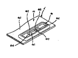
半蓋4’は、箱型に組み立てられた折り畳みコンテナー本体C1の開口部の長側壁2に沿った略半分の大きさを有する略長方形状の板部4aを有している。半蓋4’の相対する長辺部4b、4cの一方の長辺縁4bの全長に亘たって、板部4aに対して略垂直な内側垂直帯状リブ4d1が形成されており、内側垂直帯状リブ4d1の外側には、所定の間隔を置いて、外側垂直帯状リブ4d2が配置されている。相対する内側垂直帯状リブ4d1の先端と外側垂直帯状リブ4d2の先端の半分は、水平帯状リブ4eにより連結されており、相対する内側垂直帯状リブ4d1と外側垂直帯状リブ4d2の上記水平帯状リブ4eが配設されていない半分は、板部4aを延長することにより形成された水平帯状リブ4fにより連結されている。そして、上記の内側垂直帯状リブ4d1と外側垂直帯状リブ4d2と水平帯状リブ4eとにより、長辺縁4bの略半分の長さを有する、長手方向に垂直な断面が略U字状の樋状凸条部4g1が形成されており、また、内側垂直帯状リブ4d1と外側垂直帯状リブ4d2と板部4aを延長することにより形成された水平帯状リブ4fとにより、長辺縁4bの残りの半分には、内側垂直帯状リブ4d1と外側垂直帯状リブ4d2とらなる突出リブ部4g2が形成されている。なお、樋状凸条部4g1と突出リブ部4g2との境界部には、必要に応じて、内側垂直帯状リブ4dや外側垂直帯状リブ4e等とを連結する隔壁を形成することもできる。
【0023】
半蓋4’の相対する長辺部4b、4cのもう一方の長辺縁4cに沿って、上述した長側壁2の長側壁側上部雄ヒンジ部材H3に対応して、蓋側雌ヒンジ部材H4が配設されている。蓋側雌ヒンジ部材H4は、上述した樋状凸条部4g1及び突出リブ部4g2が突設されている板部4aの面4a1と反対側の面4a2に、もう一方の長辺縁4cに沿って形成されている。図14に示されているように、蓋側雌ヒンジ部材H4は、面4a2上に連接された基部h3と、基部h3の内側端に垂設された、長辺縁4cに平行な内側垂直部h4と、内側垂直部h4の上端から長辺縁4c方向に延在する水平部h5と、基部h3の外側端に垂設された、長辺縁4cに平行な外側垂直部h6と、外側垂直部h6の上部内壁に突設された、長辺縁4cに沿って下方に開口された略半円柱状の係合凹溝h7aを有するとともに、外側垂直部h6より幅の狭い柱状ブロック部h7と、基部h3と外側垂直部h6とにより形成される隅部に形成された係止突起h8とにより構成されている。なお、柱状ブロック部h7の上面h7bは、水平部h5の上面h5aより高く形成されており、また、水平部h5の先端垂直面h5bと柱状ブロック部h7の先端垂直面h7cとの間には、上述した長側壁2に配設された長側壁側上部雄ヒンジ部材H3の水平ピンh2が通過可能な間隙が形成されている。
【0024】
蓋側雌ヒンジ部材H4を構成する基部h3の両端には、長辺縁4cに対して略垂直で、且つ、長辺縁4c側が開放されたスリット4hが形成されている。また、蓋側雌ヒンジ部材H4間に位置する板部4a領域及び両端に位置する蓋側雌ヒンジ部材H4の外側に位置する板部4a領域には、該領域を、その上面4i1が、蓋側雌ヒンジ部材H4を構成する基部h3の裏面と略同じか、若干、下方に位置するように、凹ますことにより、下がった段差領域4iが形成されている。この下がった段差領域4iは、蓋側雌ヒンジ部材H4が配設されている板部4aの一方の面4a2から、一段下がって形成されているが、板部4aのもう一方の面4a1から見れば、一段上がった段差領域4jが形成されていることになる。
【0025】
半蓋4’の板部4aの相対する短辺部4k付近で、且つ、樋状凸条部4g1及び突出リブ部4g2が突出している側の板部4aの面4a1には、所定の長さで、且つ、樋状凸条部4g1や突出リブ部4g2と略同じ高さの係止凸条4mが形成されている。なお、4m1は、必要に応じて、係止凸条4mの垂直面に形成された補強リブである。また、相対する短辺部4kの一方の短辺部4k付近で、且つ、蓋側雌ヒンジ部材H4が配設されている板部4aの面4a2には、額縁状凸条枠4nが形成されており、この額縁状凸条枠4nにより囲まれた板部4aには、長方形状の透孔4n1が穿設されており、透孔4n1を形成する相対する長辺側垂直壁4n2からは、互いに接近する方向に、係合突起4n3が突設されている。なお、透孔4n1等については、再度、後述する。
【0026】
次に、図15〜図18を用いて、一例として、底部1の短辺側土手部1bに形成された底部側雌ヒンジ部材H1と短側壁3に形成された短側壁側下部雄ヒンジ部材H2及び底部側雌ヒンジ部材H1と短側壁側下部雄ヒンジ部材H2とのヒンジ連結構造について説明する。なお、底部1の長辺側土手部1aに形成された底部側雌ヒンジ部材H1と長側壁2に形成された長側壁側下部雄ヒンジ部材H2の構成及びヒンジ連結構造は、実質的に同一であるので、その詳細な説明は省略する。
【0027】
先ず最初に、底部1の短辺側土手部1bに形成された底部側雌ヒンジ部材H1について説明する。
【0028】
底部1の短辺側土手部1bの水平部1b1には、平面形状が長方形の水平孔1dが形成されており、また、短辺側土手部1bの内壁部1b2には、水平孔1dに連通するとともに、底板1e付近まで延在する方形状の縦孔1fが形成されている。縦孔1fの横幅(短辺側土手部1bの長手方向に沿った長さ)は、水平孔1dの長辺長さ(短辺側土手部1bの長手方向に沿った長さ)より短く、且つ、水平孔1dの長辺の略中央部に位置している。縦孔1fの両側に位置する内壁部1b2の内面の上端部には、内壁部1b2に対して略垂直方向に延在するフック1gが形成されており、フック1gの下面は略水平な水平面1g1として形成されており、また、上面は、外壁部1b3方向に向かって下方に傾斜した傾斜面1g2として形成されている。1hは、外壁部1b3の内面(内壁部1b2側に位置する面)に形成された垂直方向に延在する突条であり、平面的に見て、水平孔1dの中央に位置するように配置されている。
【0029】
次に、短側壁3に形成された短側壁側下部雄ヒンジ部材H2について説明する。
【0030】
短側壁3の下端水平枠3bの下面に形成された支持部10は、所定の間隔をおいて配置された一対の略方形状の支持片10aと、支持片10aを架橋する連結片10bとを有している。連結片10bは、下端水平枠3bから支持片10aの下端中央部付近まで、支持片10aに沿って延在しており、連結片10bの板部3a側の壁面10b1は、板部3aの壁面3a2と略面一になるように構成されている。また、一対の支持片10aの外側面には、外側面に垂直方向にヒンジブロック10cが形成されている。
【0031】
上述した構成を有する底部1の短辺側土手部1bに形成された底部側雌ヒンジ部材H1と短側壁3に形成された短側壁側下部雄ヒンジ部材H2とを用いて、底部1と短側壁3とをヒンジ連結するには、図15に示されているように、短側壁3が略水平状態となるように短側壁3を配置し、その後、短側壁3を、底部1に向かって下降させ、短側壁3に形成されたヒンジブロック10cを有する支持部10を、短辺側土手部1bの水平部1b1に形成された水平孔1dに挿入すると、ヒンジブロック10cを、短辺側土手部1bの外壁部1b3とフック1gとの間に配置する。
【0032】
また、上述した短側壁3の下降途中において、連結片10bが、外壁部1b3の内面に形成された突条1hに当接することになるが、突条1hの上面には傾斜面1h1が形成されているので、連結片10bは、無理なく、容易に、図17に示されているように、突条1hを越えて、突条1hの水平面1h2より下方に位置することができる。図17に示されているように、連結片10bの先端10b2は、突条1hの水平面1h2の下方に位置しているので、水平状態の短側壁3を上方に持ち上げても、連結片10cの先端10b2が、突条1hの水平面1h2に当接し、従って、短側壁3が、底部1から外れるようなことがない。
【0033】
底部1と短側壁3とがヒンジ連結された後、略水平状態の短側壁3を、略垂直に立てると、図18に示されているように、ヒンジブロック10cの一部は、フック1gの水平面1g1の下に入り込むとともに、短側壁3の下端水平枠3bが、底部1の短辺側土手部1bの水平部1b1に載置されることになる。
【0034】
上述したようにして、底部1の短辺側土手部1bに形成された底部側雌ヒンジ部材H1と短側壁3に形成された短側壁側下部雄ヒンジ部材H2とを用いて、底部1と短側壁3とをヒンジ連結する。また、同様に、底部1の長辺側土手部1aに形成された底部側雌ヒンジ部材H1と長側壁2に形成された長側壁側下部雄ヒンジ部材H2とを用いて、底部1と長側壁2とをヒンジ連結する。
【0035】
次に、図9、図12、図14、図19及び図20を用いて、上述した長側壁2に配設された長側壁側上部雄ヒンジ部材H3と半蓋4’に配設された蓋側雌ヒンジ部材H4とによる長側壁2と半蓋4’とのヒンジ連結について説明する。
【0036】
長側壁2に配設された長側壁側上部雄ヒンジ部材H3を構成する一対の支持片h1を、半蓋4’に配設された蓋側雌ヒンジ部材H4の基部h3の両端に形成されたスリット4hに挿入するように配置するとともに、長側壁側上部雄ヒンジ部材H3を構成する一対の支持片h1に架橋された水平ピンh2を、蓋側雌ヒンジ部材H4を構成する水平部h5の先端垂直面h5bと柱状ブロック部h7の先端垂直面h7cとの間に形成された間隙に挿通し、その後、長側壁側上部雄ヒンジ部材H3を構成する水平ピンh2を、蓋側雌ヒンジ部材H4を構成する柱状ブロック部h7の係合凹溝h7aに挿入する。水平ピンh2の柱状ブロック部h7の係合凹溝h7aへの挿入の際に、水平ピンh2は、基部h3と外側垂直部h6とにより形成される隅部に形成された係止突起h8を強制的に越えて、柱状ブロック部h7の係合凹溝h7aに挿入されるように構成されているので、柱状ブロック部h7の係合凹溝h7aに挿入された水平ピンh2は、係止突起h8に当接し、簡単には、柱状ブロック部h7の係合凹溝h7aから抜け出ないように構成されている。このようにして、長側壁2に配設された長側壁側上部雄ヒンジ部材H3と半蓋4’に配設された蓋側雌ヒンジ部材H4とにより、長側壁2と半蓋4’とがヒンジ連結されるように構成されている。
【0037】
なお、図1及び図21に示されているように、半蓋4’により、箱型に組み立てられた折り畳みコンテナーC1の開口部を被蓋した際に、半蓋4’の板部4aの面4a1に突設されている樋状凸条部4g1及び突出リブ部4g2が、下方に位置し、即ち、面4a1が、箱型に組み立てられた折り畳みコンテナーC1の内側に位置し、また、半蓋4’の板部4aの面4a2の突設されている額縁状凸条枠4nが、上方に位置し、即ち、面4a2が、箱型に組み立てられた折り畳みコンテナーC1の外側に位置するように、半蓋4’が、長側壁2にヒンジ連結されるように構成されている。そして、折り畳みコンテナー本体C1が、箱型に組み立てられ、半蓋4’により被蓋された際には、半蓋4’の板部4aの面4a1の突設されている樋状凸条部4g1の端部及び突出リブ部4g2の端部が、短側壁3の上端水平枠3eの中央領域に形成された凹部3e1に挿入されるとともに、半蓋4’の板部4aの面4a1に形成された係止凸条4mが、板部3aの上端から若干下がった位置に形成された上部水平枠3dの上方に配置されるように構成されている。
【0038】
図2に示されているように、折り畳みコンテナー本体C1が、箱型に組み立てられた後に、長側壁側上部雄ヒンジ部材H3と半蓋4’に配設された蓋側雌ヒンジ部材H4とにより構成されたヒンジ部により、長側壁2に重なるように垂下されている半蓋4’を、折り畳みコンテナー本体C1の開口部方向に、略270度回動させて、図1に示されているように、折り畳みコンテナー本体C1の開口部を、蓋部材4を構成する2枚の半蓋4’により被蓋する。折り畳みコンテナー本体C1を、半蓋4’により被蓋した際には、半蓋4’の板部4aの面4a1(折り畳みコンテナー本体C1の開口部を被蓋した半蓋4’の裏面側)に突設されている樋状凸条部4g1の端部及び突出リブ部4g2の端部は、短側壁3の上端水平枠3eの中央領域に形成された凹部3e1に挿入されるとともに、同じく、半蓋4’の板部4aの面4a1(折り畳みコンテナー本体C1の開口部を被蓋した半蓋4’の裏面側)に形成された係止凸条4mが、板部3aの上端から若干下がった位置に形成された上部水平枠3dの上方に配置されるように構成されている。更に、半蓋4’の板部4aの面4a2に突設された額縁状凸条枠4nが、折り畳みコンテナー本体C1の開口部を被蓋した半蓋4’の上面側に位置するように構成されている。
【0039】
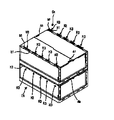
図22に示されているように、箱型に組み立てられ、蓋部材4を構成する2枚の半蓋4’で被蓋された折り畳みコンテナーCを、段積みした際には、上に位置する折り畳みコンテナーCaの底部1の裏面に形成されている嵌合膨出部1cが、下に位置する折り畳みコンテナーCbの相対する長側壁2に配設され、半蓋4’の上面を越えて上方に延在している長側壁側上部雄ヒンジ部材H3の支持片h1の内側に位置するとともに、2枚の半蓋4’の上面側に、点対象の位置にある2個の額縁状凸条枠4nの内側に位置するように構成されているので、上に位置する折り畳みコンテナーCaが水平方向に移動しようとしても、上に位置する折り畳みコンテナーCaの底部1の嵌合膨出部1cが、下に位置する折り畳みコンテナーCbの長側壁側上部雄ヒンジ部材H3を構成する支持片h1及び額縁状凸条枠4nに当接し、上に位置する折り畳みコンテナーCaの水平方向の移動が制限されるので、安定した状態で、多数の折り畳みコンテナーCを段積みすることができる。なお、額縁状凸条枠4nに代えて、或いは、額縁状凸条枠4nに加えて、半蓋4’の面4a2には、上に位置する折り畳みコンテナーCaの短側壁3方向への移動を制限する、上述した係止凸条4mと同様の凸条を形成することもできる。
【0040】
ところで、箱型に組み立てられた折り畳みコンテナーの折り畳み作業の過程においては、図3に示されているように、短側壁3が底部1に重なるように倒された後に、略垂直に立てられ、且つ、半蓋4’が重なるように垂下されている状態の長側壁2を、底部1方向に倒すことになるが、長側壁2が、略垂直に立てられ、且つ、半蓋4’が重なるように垂下されている状態においては、上述したように、長側壁2に配設された長側壁側上部雄ヒンジ部材H3の一対の支持片h1に架橋された水平ピンh2が、半蓋4’に配設された蓋側雌ヒンジ部材H4を構成する柱状ブロック部h7の係合凹溝h7aに挿入されている。このようなヒンジ連結状態でヒンジ連結されている長側壁2と半蓋4’を、半蓋4’が重なるように垂下されている長側壁2を、底部1に重ねられている短側壁3に重なるように倒すと、一方の長側壁2と半蓋4’のヒンジ部を構成する長側壁側上部雄ヒンジ部材H3と蓋側雌ヒンジ部材H4と、もう一方の長側壁2と半蓋4’のヒンジ部を構成する長側壁側上部雄ヒンジ部材H3と蓋側雌ヒンジ部材H4とは、略中央部において、対向するように位置するとともに、図23に示されているように、長側壁2に配設された長側壁側上部雄ヒンジ部材H3の一対の支持片h1に架橋された水平ピンh2が、半蓋4’に配設された蓋側雌ヒンジ部材H4を構成する柱状ブロック部h7の係合凹溝h7aに挿入されているので、図4に示されているように、長側壁2に重ねられている半蓋4’の底部1の長辺側土手部1a側の縁部が、底部1の長辺側土手部1aから、外側にはみ出しており、且つ、水平状態の半蓋4’間に間隙Dが生じている。また、この状態においては、図4に示されているように、相対する半蓋4’のスリット4h間に形成されている、板部4a一方の面4a1から見て、一段上がった状態の段差領域4jは、互い違いに配置されるように構成されている。
【0041】
図23に示されているような、長側壁2に配設された長側壁側上部雄ヒンジ部材H3の一対の支持片h1に架橋された水平ピンh2が、半蓋4’に配設された蓋側雌ヒンジ部材H4を構成する柱状ブロック部h7の係合凹溝h7aに挿入されている状態から、相対している半蓋4’の蓋側雌ヒンジ部材H4付近を下方に押すと、図24に示されているように、長側壁側上部雄ヒンジ部材H3の水平ピンh2が、蓋側雌ヒンジ部材H4を構成する柱状ブロック部h7の係合凹溝h7aから抜け出ることになる。このように、長側壁側上部雄ヒンジ部材H3の水平ピンh2が、蓋側雌ヒンジ部材H4を構成する柱状ブロック部h7の係合凹溝h7aから抜け出た状態において、相対している半蓋4’を、互いに接近する方向に押すと、図25に示されているように、長側壁側上部雄ヒンジ部材H3の水平ピンh2は、蓋側雌ヒンジ部材H4を構成する基部h3と内側垂直部h4と水平部h5とにより形成される水平凹部h9に入り込むことになる。このように、蓋側雌ヒンジ部材H4を構成する基部h3と内側垂直部h4と水平部h5とにより形成される水平凹部h9が形成されており、この水平凹部h9には、蓋側雌ヒンジ部材H4を構成する柱状ブロック部h7の係合凹溝h7aから抜け出た長側壁側上部雄ヒンジ部材H3の水平ピンh2が挿入可能なように構成されており、従って、倒された水平状態の長側壁2に重ねられている半蓋4’が、互いに接近する方向に移動可能なように構成されているので、図4に示されているように、底部1の長辺側土手部1aから外側にはみ出している半蓋4’の底部1の長辺側土手部1a側の縁部が、引っ込んで、図5に示されているように、半蓋4’が、底部1からはみ出すようなことがなくなり、従って、よりコンパクトな状態に折り畳みコンテナーを折り畳むことができることになる。
【0042】
上述したように、図4に示されている状態から、相対する半蓋4’を、互いに接近する方向に移動させた際には、一方の半蓋4’に形成された段差領域4jは、もう一方の半蓋4’の板部4aの上に重ねられるように移動し、また、もう一方の半蓋4’に形成された段差領域4jは、一方の半蓋4’の板部4aの上に重ねられるように移動することになり、図4に示されているように、半蓋4’間に存在する間隙Dが、段差領域4jにより閉ざされることになる。なお、折り畳みコンテナーを、箱型に組み立てる際には、上述したと逆の工程により、長側壁側上部雄ヒンジ部材H3の水平ピンh2を、蓋側雌ヒンジ部材H4を構成する基部h3と内側垂直部h4と水平部h5とにより形成される水平凹部h9から抜き出すとともに、蓋側雌ヒンジ部材H4を構成する柱状ブロック部h7の係合凹溝h7aに挿入して、長側壁側上部雄ヒンジ部材H3と蓋側雌ヒンジ部材H4とによる通常のヒンジ状態に戻す。
【0043】
また、図5に示されているように、折り畳みコンテナー本体C1が折り畳まれ、且つ、蓋部材4を構成する半蓋4’が、長側壁2に載置された状態においては、蓋部材4の上面の底部1の長辺側土手部1a側には、樋状凸条部4g1及び突出リブ部4g2が位置し、また、蓋部材4を構成する半蓋4’の上面の底部1の短側壁土手部1b側には、係止凸条4mが位置するように構成されている。そして、折り畳まれた状態の折り畳みコンテナーを、段積みした際には、上に位置する折り畳まれた状態の折り畳みコンテナーの底部1の裏面に形成された嵌合膨出部1cは、下に位置する折り畳まれた状態の折り畳みコンテナーの蓋部材4を構成する半蓋4’の樋状凸条部4g1と突出リブ部4g2及び係止凸条4mにより囲まれた領域に載置されるように構成されているので、上に位置する折り畳まれた状態の折り畳みコンテナーが水平方向に移動しようとしても、その移動が、下に位置する折り畳まれた状態の折り畳みコンテナーの蓋部材4を構成する半蓋4’の樋状凸条部4g1と突出リブ部4g2及び係止凸条4mにより阻止されることになり、従って、安定した状態で、多数の折り畳まれた状態の折り畳みコンテナーを段積みすることができるとともに、上に位置する折り畳まれた状態の折り畳みコンテナーが、下に位置する折り畳まれた状態の折り畳みコンテナーから落下するようなことが防止できる。
【0044】
なお、図3に示されているように、短側壁3が、底部1に重ねられた状態においては、短側壁3に形成されている凸条部3iが、底部1の上面に載置されるように構成されている。このように、短側壁3に形成されている凸条部3iが、底部1の上面に載置されるように構成されているので、倒された短側壁3を、略水平状態に維持することができ、従って、短側壁3に重ねられる長側壁2を、同様に、略水平状態に維持することができるので、折り畳まれた状態の折り畳みコンテナーを、安定した状態で段積みすることができる。また、短側壁3と長側壁2とを略水平状態に維持することができるので、折り畳まれた状態の折り畳みコンテナーの圧縮強度が増加し、折り畳まれた状態の折り畳みコンテナーを、更に安定した状態で段積みすることができる。
【0045】
なお、図3に示されているように、短側壁3が底部1に重ねられ、長側壁2が略垂直に立てられている状態から、短側壁3を垂直方向に回動させると、短側壁3の回動途中において、短側壁3の端部垂直枠3cの外側に位置する板部3aの帯状領域3a1に形成された雄ブロック3hが、長側壁2の板部2aの垂直縁付近に配設された雌ブロック2cの凹部2c1に挿入されるように構成されている。
【0046】
次に、図26〜図33を用いて、ロック部材Kについて説明する。
【0047】
ロック部材Kは、上下方向に対向するように位置する一対の長方形状のロック板k1と、2枚のロック板k1の中央部を連結する、略角柱状の連結支柱k2とを有しており、ロック板k1の長辺k1a側に位置する連結支柱k2の相対する側面の中央部には、縦方向に延在する凹部k3が形成されている。この凹部k3には、上述した半蓋4’に形成された額縁状凸条枠4n内に穿設された長方形状の透孔4n1の相対する長辺側垂直壁4n2に突設された係合突起4n3が嵌入可能なように構成されている。また、連結支柱k2の略中間部には、凹部k3が形成されている連結支柱k2の相対する側面から突出した板状の張出部k4が形成されており、張出部k4のロック板k1の短辺k1bに沿った幅は、額縁状凸条枠4n内に穿設された長方形状の透孔4n1の長辺側垂直壁4n2間の幅より狭く形成されており、従って、張出部k4が、透孔4n1を通過できるように構成されている。
【0048】
なお、ロック部材Kは、連結支柱k2が、額縁状凸条枠4n内に穿設された長方形状の透孔4n1に挿入されるように、半蓋4’に配設されることになるが、ロック部材Kを、一方のロック板k1と、一方のロック板k1が無い状態の部材とにより、合成樹脂等により分割して成形し、一方のロック板k1が無い状態の部材の連結支柱k2を、額縁状凸条枠4n内に穿設された長方形状の透孔4n1に挿入した後、連結支柱k2の端部に、一方のロック板k1を接着することにより、ロック部材Kを、半蓋4’の額縁状凸条枠4n内に穿設された長方形状の透孔4n1に挿入することができる。また、図29に示されているように、一方のロック板k1に2本のフックk5a付き脚部k5を形成するとともに、もう一方のロック板k1の連結支柱k2付近に嵌合孔k6を穿設し、連結支柱k2を、額縁状凸条枠4n内に穿設された長方形状の透孔4n1に挿入した後、一方のロック板k1に形成された脚部k5を、もう一方のロック板k1に穿設された嵌合孔k6に挿入するとともに、脚部k5のフックk5aを、もう一方のロック板k1に引っ掛け係止させることにより、ロック部材Kを、半蓋4’の額縁状凸条枠4n内に穿設された長方形状の透孔4n1に挿入するように構成することもできる。
【0049】
次に、図1に示されているように、箱型に組み立てられた折り畳みコンテナー本体C1の開口部に、半蓋4’が被蓋された状態におけるロック部材Kの施錠状態及び施錠解除状態について説明する。
【0050】
折り畳みコンテナー本体C1が、半蓋4’により被蓋された状態で、且つ、図30に示されているように、ロック部材Kの連結支柱k2が、半蓋4’の額縁状凸条枠4n内に穿設された透孔4n1の長側壁2側の短辺垂直壁4n4に当接或いは接近して位置している場合には、ロック部材Kの下方に位置するロック板k1が、短側壁3の上端水平枠3eに穿設された長方形状の透孔3g内に挿通されているとともに、下方に位置するロック板k1の上面k1cが、短側壁3の上端水平枠3eの下面3e2より下方に位置している。この状態が、図30に示されているロック部材Kの施錠解除状態である。この施錠解除状態においては、この状態から、半蓋4’を、長側壁2に配設された長側壁側上部雄ヒンジ部材H3と半蓋4’に配設された蓋側雌ヒンジ部材H4によるヒンジ部を中心に、上方に回動させると、半蓋4’に配設されたロック部材Kの下方に位置するロック板k1が、短側壁3の上端水平枠3eに穿設された透孔3gから抜け出るように構成されている。なお、ロック部材Kの上方に位置するロック板k1は、半蓋4’に配設された額縁状凸条枠4n内に、透孔4n1の長辺側垂直壁4n2に沿って移動できるように挿入されている。
【0051】
上述したロック部材Kの施錠解除状態から、ロック部材Kを、半蓋4’の樋状凸条部4g1及び突出リブ部4g2方向、換言すれば、長側壁2から遠ざかる方向に移動させると、ロック部材Kの下方に位置するロック板k1の移動方向前方の先端部分k1’が、図31に示されているように、短側壁3の上端水平枠3eの下面3e2の下方に入り込むとともに、半蓋4’の額縁状凸条枠4n内に穿設された透孔4n1の長辺側垂直壁4n2に突設された係合突起4n3が、ロック部材Kの連結支柱k2に形成された凹部k3に嵌合されて、簡単には、ロック部材Kが移動しないように構成されている。この状態が、半蓋4’が、ロック部材Kを介して、短側壁3に施錠された施錠状態である。なお、施錠状態を解除するには、ロック部材Kを、長側壁2側に移動させて、ロック部材Kの下方に位置するロック板k1の上記移動方向前方の先端部分k1’を、短側壁3の上端水平枠3eの下面3e2から排除し、その後、半蓋4’を、長側壁2に配設された長側壁側上部雄ヒンジ部材H3と半蓋4’に配設された蓋側雌ヒンジ部材H4とによるヒンジ部を中心に、上方に回動させると、ロック部材Kの下方に位置するロック板k1が、短側壁3の上端水平枠3eに穿設された長方形状の透孔3gから抜け出て、半蓋4’を、長側壁2に重なるまで回動させことができる。なお、上記の施錠状態において、ロック部材Kの連結支柱k2に形成された凹部k3に、額縁状凸条枠4n内に穿設された長方形状の透孔4n1の相対する長辺側垂直壁4n2に突設された係合突起4n3が嵌入された状態では、係合突起4n3の直ぐ下に、連結支柱k2の略中間部に突設された張出部k4が位置しているので、ロック部材Kが上下方向へ移動しようとしても、係合突起4n3が張出部k4に当接し、その移動が制限されるので、ロック部材Kの上下方向の移動も少なく、ロック部材Kの施錠解除が、不用意に行われることを防止することができる。
【0052】
次に、図5に示されているように、折り畳みコンテナーが折り畳まれた状態における、半蓋4’に配設されたロック部材Kの下に位置する長側壁2に対する施錠状態及び施錠解除状態について説明する。
【0053】
ところで、図8及び図32に示されているように、長側壁2の周縁枠部2bを構成する垂直枠2b3の下端部には、上枠2d1と、下枠2d2と、上枠2d1と下枠2d2とを連結する垂直枠2d3と、長側壁2の周縁枠部2bを構成する垂直枠2b3とにより囲まれた長方形状の角筒2dが形成されている。また、上記の角筒2dの周縁枠部2bの先端側に位置する下端水平枠2b1側部分は、閉鎖壁2d4により閉鎖されている。
【0054】
折り畳みコンテナーが折り畳まれた状態においては、図33に示されているように、半蓋4’は、長側壁2の上に載置されているとともに、半蓋4’に形成された額縁状凸条枠4nは、半蓋4’の裏面に位置しており、且つ、ロック部材Kの上方に位置するロック板k1は、半蓋4’の額縁状凸条枠4nが配設されていない板部4aの面4a1に載置されている。そして、ロック部材Kの施錠解除状態においては、ロック部材Kの下方に位置するロック板k1は、長側壁2に形成された長方形状の角筒2dに挿通されているとともに、ロック部材Kの下方に位置するロック板k1の上面k1dは、長側壁2に形成された角筒2dの一部を閉鎖する閉鎖壁2d4の裏面2d4’から外れた位置にある。この状態から、ロック部材Kを、半蓋4’の樋状凸条部4g1及び突出リブ部4g2方向、換言すれば、底部1の長辺側土手部1a方向に移動させると、ロック部材Kの下方に位置するロック板k1の移動方向前方の先端部分k1”が、図34に示されているように、長側壁2に形成された角筒2dの一部を閉鎖する閉鎖壁2d4の裏面2d4’の下方に入り込むとともに、半蓋4’の額縁状凸条枠4n内に穿設された透孔4n1の長辺側垂直壁4n2に突設された係合突起4n3が、ロック部材Kの連結支柱k2に形成された凹部k3に嵌合されて、簡単には、ロック部材Kが移動しないように構成されている。この状態が、半蓋4’が、ロック部材Kを介して、長側壁2に施錠された施錠状態である。
【0055】
上述した半蓋4’と長側壁2とのロック部材Kによる施錠状態から、長側壁2と半蓋4’のロック部材Kにより施錠状態を解除するには、ロック部材Kを、長側壁2に配設された長側壁側上部雄ヒンジ部材H3と半蓋4’に配設された蓋側雌ヒンジ部材H4とによるヒンジ部方向に移動させて、ロック部材Kの下方に位置するロック板k1の上述した先端部分k1”を、図33に示されているように、長側壁2に形成された角筒2dの一部を閉鎖する閉鎖壁2d4の裏面2d4’から排除する。このようにして、長側壁2と半蓋4’のロック部材Kにより施錠状態を解除することができる。
【0056】
上述したように、箱型に組み立てられ、且つ、蓋部材4を構成する半蓋4’により被蓋された折り畳みコンテナーの短側壁3が、半蓋4’に配設されたロック部材Kにより、施錠されるとともに、折り畳まれた状態においても、半蓋4’の下方に位置する長側壁2が、半蓋4’に配設されたロック部材Kにより、施錠されるように構成されているので、箱型に組み立てられ状態においても、折り畳まれた状態においても、半蓋4’の回動を阻止することができる。
【0057】
【発明の効果】
本発明は、以上説明した構成を有しているので、以下に記載する効果を奏するものである。
【0058】
箱型に組み立てられ、且つ、蓋部材により被蓋された折り畳みコンテナーが、段積みされた状態において、上に位置する折り畳みコンテナーの水平移動が、下に位置する蓋部材に配設された移動阻止部材により、その水平移動が制限されるとともに、折り畳まれ、且つ、蓋部材が載置された折り畳みコンテナーを、段積みした状態においても、上に位置する折り畳まれた折り畳みコンテナーの水平移動が、下に位置する蓋部材に配設された移動阻止部材により、その水平移動が制限されるように構成されているので、箱型に組み立てられ状態においても、折り畳まれた状態においても、蓋付き折り畳みコンテナーを、安定した状態で段積みすることができる。
【図面の簡単な説明】
【図1】図1は本発明の蓋付き折り畳みコンテナーが箱型に組み立てられた状態の斜視図である。
【図2】図2は本発明の蓋付き折り畳みコンテナーが箱型に組み立てられ、且つ、蓋部材により被蓋が解除された状態の斜視図である。
【図3】図3は本発明の蓋付き折り畳みコンテナーの折り畳み途中或いは組み立て途中の斜視図である。
【図4】図4は本発明の蓋付き折り畳みコンテナーの折り畳み途中或いは組み立て途中の斜視図である。
【図5】図5は本発明の蓋付き折り畳みコンテナーが折り畳まれた状態の斜視図である。
【図6】図6は本発明の蓋付き折り畳みコンテナーを構成する底部の斜視図である。
【図7】図7は本発明の蓋付き折り畳みコンテナーを構成する底部の裏面斜視図である。
【図8】図8は本発明の蓋付き折り畳みコンテナーを構成する長側壁の外側からの斜視図である。
【図9】図9は本発明の蓋付き折り畳みコンテナーを構成する長側壁の内側からの斜視図である。
【図10】図10は本発明の蓋付き折り畳みコンテナーを構成する短側壁の外側からの斜視図である。
【図11】図11は本発明の蓋付き折り畳みコンテナーを構成する短側壁の内側からの斜視図である。
【図12】図12は本発明の蓋付き折り畳みコンテナーを構成する蓋部材の一方の半蓋の斜視図である。
【図13】図13は本発明の蓋付き折り畳みコンテナーを構成する蓋部材の一方の半蓋の裏面斜視図である。
【図14】図14は本発明の蓋付き折り畳みコンテナーを構成する蓋部材の蓋側雌ヒンジ部材の拡大斜視図である。
【図15】図15は本発明の蓋付き折り畳みコンテナーの側壁と底部をヒンジ連結する一例としてのヒンジ部材の分解斜視図である。
【図16】図16は本発明の蓋付き折り畳みコンテナーの側壁と底部をヒンジ連結する一例としてのヒンジ部の部分垂直断面図である。
【図17】図17は同じく本発明の蓋付き折り畳みコンテナーの側壁と底部をヒンジ連結する一例としてのヒンジ部の部分垂直断面図である。
【図18】図18は同じく本発明の蓋付き折り畳みコンテナーの側壁と底部をヒンジ連結する一例としてのヒンジ部の部分垂直断面図である。
【図19】図19は本発明の蓋付き折り畳みコンテナーを構成する長側壁と半蓋との部分分解斜視図である。
【図20】図20は本発明の蓋付き折り畳みコンテナーを構成する長側壁と半蓋との部分斜視図である。
【図21】図21は本発明の蓋付き折り畳みコンテナーが箱型に組み立てられ、且つ、蓋部材により被蓋された状態の部分斜視図である。
【図22】図22は本発明の蓋付き折り畳みコンテナーが箱型に組み立てられ、且つ、蓋部材により被蓋された状態の段積み状態を示す斜視図である。
【図23】図23は本発明の蓋付き折り畳みコンテナーの半蓋が長側壁に重ねられた状態の部分斜視図である。
【図24】図24は同じく本発明の蓋付き折り畳みコンテナーの半蓋が長側壁に重ねられた状態の部分斜視図である。
【図25】図25は同じく本発明の蓋付き折り畳みコンテナーの半蓋が長側壁に重ねられた状態の部分斜視図である。
【図26】図26は本発明の蓋付き折り畳みコンテナーを構成する半蓋の額縁状凸条枠付近の部分拡大斜視図である。
【図27】図27は本発明の蓋付き折り畳みコンテナーを構成する半蓋に配設された額縁状凸条枠の平面図である。
【図28】図28は本発明の蓋付き折り畳みコンテナーを構成するロック部材の斜視図である。
【図29】図29は本発明の蓋付き折り畳みコンテナーを構成する一例としてのロック部材の分解斜視図である。
【図30】図30は本発明の蓋付き折り畳みコンテナーを構成する半蓋と短側壁のロック部材を含む部分垂直断面図である。
【図31】図31は同じく本発明の蓋付き折り畳みコンテナーを構成する半蓋と短側壁のロック部材を含む部分垂直断面図である。
【図32】図32は本発明の蓋付き折り畳みコンテナーを構成する半蓋と長側壁と底部の部分分解斜視図である。
【図33】図33は本発明の蓋付き折り畳みコンテナーを構成する半蓋と長側壁のロック部材を含む部分垂直断面図である。
【図34】図34は同じく本発明の蓋付き折り畳みコンテナーを構成する半蓋と長側壁のロック部材を含む部分垂直断面図である。
【符号の説明】
H1・・・・・・・・・・・・・底部側雌ヒンジ部材
H2・・・・・・・・・・・・・長側壁側下部雄ヒンジ部材
H3・・・・・・・・・・・・・長側壁側上部雄ヒンジ部材
H4・・・・・・・・・・・・・蓋側雌ヒンジ部材
K・・・・・・・・・・・・・・ロック部材
1・・・・・・・・・・・・・・底部
2・・・・・・・・・・・・・・長側壁
3・・・・・・・・・・・・・・短側壁
4・・・・・・・・・・・・・・蓋部材
4’・・・・・・・・・・・・・半蓋[0001]
BACKGROUND OF THE INVENTION
The present invention relates to a folding container with a lid in which a side wall hinged to the bottom can be folded so as to overlap the bottom, and a lid is disposed on one opposite side wall.
[0002]
[Prior art]
2. Description of the Related Art Conventionally, a folding container with a lid in which a half lid constituting a lid member is hinge-connected to the upper ends of opposing side walls constituting the folding container main body is known (for example, Japanese Patent Publication No. 8-510981). It has been.
[0003]
[Problems to be solved by the invention]
When the above-described conventional folding container with a lid is stacked in a box-shaped assembled state or a folded state, the folding container located above is placed on the lid member of the folding container located below. In the case of moving in the horizontal direction, the lid member of the folding container located below is not provided with a blocking member for restricting the horizontal movement of the folding container located above, so the folding member located above There was a problem that the container could not be stacked in a stable state by shifting from the folding container located below. In addition, there is also a problem that the folding container located on the upper side falls from the folding container located on the lower side.
[0004]
The objective of this invention is solving the subject which the conventional folding container with a lid | cover mentioned above has.
[0005]
[Means for Solving the Problems]
To achieve the above-mentioned object, the present invention is a box-shaped folding container having a bottom part, a side wall hinged to the bottom part, and a lid member hinged to the upper end part of the opposite side wall. In addition, when the folding containers covered by the lid member are stacked, the horizontal movement of the folding container located on the upper side is prevented by the movement blocking member disposed on the lid member located below. The lid member is located under the horizontal movement of the folded folding container located on the upper side even when the folded folding containers on which the movement is restricted and the lid member is placed are stacked. The horizontal movement is limited by the movement preventing member disposed in the.
[0006]
【Example】
Examples of the present invention will be described below. However, the present invention is not limited to these examples as long as the gist of the present invention is not exceeded.
[0007]
First, the overall configuration, folding order, and assembly order of the lidded folding container will be described with reference to FIGS.
[0008]
A folding container with a lid (hereinafter, also simply referred to as a folding container) includes a
[0009]
As shown in FIG. 1, in order to fold a folding container covered with a
[0010]
In order to assemble from the folded state shown in FIG. 5 into a box shape as shown in FIG. 1, the assembling work may be performed in the order opposite to the folding order described above. That is, from the state shown in FIG. 5, the
[0011]
Next, the
[0012]
As described above, the long side bank portion 1a is formed on the long side opposite to the
[0013]
Next, the
[0014]
The
[0015]
2c is a female block disposed in the vicinity of the vertical edge of the plate portion 2a where the
[0016]
On the upper surface of the upper end horizontal frame 2b2 constituting the
[0017]
Next, the
[0018]
The
[0019]
Further, the lower side
[0020]
Further, a male block extending substantially perpendicular to the plate portion 3a along the end vertical frame 3c is provided in the band-like region 3a1 of the plate portion 3a located outside the end vertical frame 3c formed on the
[0021]
Next, the
[0022]
Half lid 4 'has the substantially rectangular-shaped board part 4a which has a half size along the
[0023]
The lid-side female hinge member H4 corresponds to the long-side-side upper male hinge member H3 of the
[0024]
At both ends of the base h3 constituting the lid-side female hinge member H4, slits 4h that are substantially perpendicular to the long side edge 4c and open on the long side edge 4c side are formed. In addition, the plate portion 4a region located between the lid-side female hinge members H4 and the plate portion 4a region located outside the lid-side female hinge members H4 located at both ends are divided into the region, the upper surface 4i1 of which is the lid side. A stepped region 4i that is lowered is formed by being recessed so as to be substantially the same as or slightly below the back surface of the base h3 that constitutes the female hinge member H4. The lowered step region 4i is formed one step down from one surface 4a2 of the plate portion 4a on which the lid-side female hinge member H4 is disposed, but can be seen from the other surface 4a1 of the plate portion 4a. In this case, the step region 4j raised by one step is formed.
[0025]
The surface 4a1 of the plate portion 4a on the side where the plate-like protruding portion 4g1 and the protruding rib portion 4g2 protrude in the vicinity of the opposing short side portion 4k of the plate portion 4a of the half lid 4 'has a predetermined length. And the latching protrusion 4m of the height substantially the same as the collar-shaped protrusion 4g1 and the protrusion rib part 4g2 is formed. In addition, 4m1 is a reinforcing rib formed on the vertical surface of the locking projection 4m as necessary. Further, a frame-like protruding frame 4n is formed in the vicinity of one short side 4k of the opposing short side 4k and on the surface 4a2 of the plate 4a on which the lid-side female hinge member H4 is disposed. The plate portion 4a surrounded by the frame-like protruding frame 4n is provided with a rectangular through hole 4n1, and from the opposing long side vertical walls 4n2 forming the through hole 4n1, Engagement protrusions 4n3 are provided so as to protrude toward each other. The through holes 4n1 and the like will be described later again.
[0026]
Next, using FIG. 15 to FIG. 18, as an example, a bottom side female hinge member H <b> 1 formed on the short side bank portion 1 b of the
[0027]
First, the bottom side female hinge member H1 formed on the short side bank 1b of the bottom 1 will be described.
[0028]
The horizontal portion 1b1 of the short side bank portion 1b of the
[0029]
Next, the short side wall lower male hinge member H2 formed on the
[0030]
The
[0031]
The
[0032]
Further, while the
[0033]
After the
[0034]
As described above, the
[0035]
Next, with reference to FIGS. 9, 12, 14, 19 and 20, the long side wall-side upper male hinge member H3 disposed on the
[0036]
A pair of support pieces h1 constituting the long-side-wall-side upper male hinge member H3 disposed on the long-
[0037]
As shown in FIGS. 1 and 21, when the opening of the folding container C1 assembled in a box shape is covered with the
[0038]
As shown in FIG. 2, after the folding container body C1 is assembled into a box shape, the long side wall side upper male hinge member H3 and the lid side female hinge member H4 disposed on the
[0039]
As shown in FIG. 22, the folded containers C that are assembled in a box shape and covered with two half-
[0040]
By the way, in the process of folding the folding container assembled in a box shape, as shown in FIG. 3, after the
[0041]
As shown in FIG. 23, a horizontal pin h2 bridged with a pair of support pieces h1 of the long side wall-side upper male hinge member H3 disposed on the
[0042]
As described above, when the opposing
[0043]
Further, as shown in FIG. 5, when the folding container main body C <b> 1 is folded and the
[0044]
As shown in FIG. 3, in a state where the
[0045]
As shown in FIG. 3, when the
[0046]
Next, the lock member K will be described with reference to FIGS.
[0047]
The lock member K includes a pair of rectangular lock plates k1 positioned so as to face each other in the vertical direction, and a substantially prismatic connection column k2 that connects the central portions of the two lock plates k1. A concave portion k3 extending in the vertical direction is formed at the central portion of the opposing side surface of the connecting column k2 located on the long side k1a side of the lock plate k1. In this recess k3, there is an engagement projecting on the opposing long side vertical wall 4n2 of the rectangular through hole 4n1 formed in the frame-like protruding frame 4n formed in the half lid 4 'described above. The protrusion 4n3 is configured to be fitted. Further, a plate-like overhanging portion k4 protruding from the opposite side surface of the connecting column k2 in which the concave portion k3 is formed is formed at a substantially middle portion of the connecting column k2, and the lock plate k1 of the overhanging portion k4 is formed. The width along the short side k1b is formed narrower than the width between the long side vertical walls 4n2 of the rectangular through holes 4n1 drilled in the frame-like protruding frame 4n. k4 is configured to be able to pass through the through hole 4n1.
[0048]
The lock member K is disposed on the
[0049]
Next, as shown in FIG. 1, the locking state and the unlocking state of the locking member K in a state where the
[0050]
In a state where the folding container body C1 is covered with the
[0051]
When the lock member K is moved from the unlocked state of the lock member K described above in the direction of the flange-shaped convex portion 4g1 and the protruding rib portion 4g2 of the half lid 4 ', in other words, in the direction away from the
[0052]
Next, as shown in FIG. 5, the locked state and the unlocked state with respect to the
[0053]
8 and 32, the upper frame 2d1, the lower frame 2d2, the upper frame 2d1, and the lower frame are provided at the lower end of the vertical frame 2b3 constituting the
[0054]
In the state in which the folding container is folded, as shown in FIG. 33, the
[0055]
In order to release the locked state by the locking member K of the
[0056]
As described above, the
[0057]
【The invention's effect】
Since the present invention has the above-described configuration, the following effects can be achieved.
[0058]
When folding containers assembled in a box shape and covered by a lid member are stacked, horizontal movement of the folding container located on the upper side is prevented from moving on the lid member located below. The horizontal movement is limited by the member, and even when the folded folding container with the lid member placed thereon is stacked, the horizontal movement of the folded folding container positioned above is Since the horizontal movement is restricted by the movement preventing member disposed on the lid member located in the lid member, the folded container with the lid can be assembled in a box shape or in a folded state. Can be stacked in a stable state.
[Brief description of the drawings]
FIG. 1 is a perspective view of a folding container with a lid according to the present invention assembled in a box shape.
FIG. 2 is a perspective view showing a state in which a folding container with a lid according to the present invention is assembled into a box shape, and the lid is released by a lid member.
FIG. 3 is a perspective view of a folding container with a lid according to the present invention during folding or assembling.
FIG. 4 is a perspective view of the folding container with a lid according to the present invention during folding or assembling.
FIG. 5 is a perspective view of the folded container with a lid according to the present invention in a folded state.
FIG. 6 is a perspective view of the bottom part of the folding container with a lid according to the present invention.
FIG. 7 is a rear perspective view of the bottom part of the folding container with a lid according to the present invention.
FIG. 8 is a perspective view from the outside of the long side wall constituting the folding container with a lid of the present invention.
FIG. 9 is a perspective view from the inside of a long side wall constituting the folding container with a lid of the present invention.
FIG. 10 is a perspective view from the outside of a short side wall constituting the lidded folding container of the present invention.
FIG. 11 is a perspective view from the inside of a short side wall constituting the folding container with a lid of the present invention.
FIG. 12 is a perspective view of one half lid of the lid member constituting the folding container with lid of the present invention.
FIG. 13 is a rear perspective view of one half lid of the lid member constituting the folding container with lid of the present invention.
FIG. 14 is an enlarged perspective view of a lid-side female hinge member of a lid member constituting the folding container with lid of the present invention.
FIG. 15 is an exploded perspective view of a hinge member as an example for hinge-connecting a side wall and a bottom of a folding container with a lid according to the present invention.
FIG. 16 is a partial vertical cross-sectional view of a hinge part as an example for hinge-connecting a side wall and a bottom part of a folding container with a lid according to the present invention.
FIG. 17 is a partial vertical cross-sectional view of a hinge portion as an example in which the side wall and the bottom portion of the folding container with a lid according to the present invention are hinge-connected.
FIG. 18 is a partial vertical sectional view of a hinge portion as an example in which the side wall and the bottom portion of the folding container with a lid according to the present invention are hinge-connected.
FIG. 19 is a partially exploded perspective view of a long side wall and a half lid constituting the folding container with a lid of the present invention.
FIG. 20 is a partial perspective view of a long side wall and a half lid constituting a folding container with a lid according to the present invention.
FIG. 21 is a partial perspective view of a folding container with a lid according to the present invention assembled into a box shape and covered with a lid member.
FIG. 22 is a perspective view showing a stacked state in which folding containers with a lid according to the present invention are assembled in a box shape and covered with a lid member.
FIG. 23 is a partial perspective view showing a state in which the half lid of the folding container with a lid according to the present invention is overlaid on the long side wall.
FIG. 24 is a partial perspective view showing a state in which the half lid of the folding container with a lid according to the present invention is overlaid on the long side wall.
FIG. 25 is a partial perspective view showing a state in which the half lid of the folding container with a lid according to the present invention is overlaid on the long side wall.
FIG. 26 is a partially enlarged perspective view of the vicinity of a frame-like convex frame of a half lid constituting the folding container with a lid of the present invention.
FIG. 27 is a plan view of a frame-like convex frame disposed on a half-cover constituting the folding container with a lid of the present invention.
FIG. 28 is a perspective view of a lock member constituting the lidded folding container of the present invention.
FIG. 29 is an exploded perspective view of a lock member as an example constituting the folding container with a lid of the present invention.
FIG. 30 is a partial vertical sectional view including a half lid and a short side wall lock member constituting the folding container with a lid of the present invention.
FIG. 31 is a partial vertical cross-sectional view including a half lid and a short side wall lock member that also constitute a folding container with a lid according to the present invention.
FIG. 32 is a partially exploded perspective view of a half lid, a long side wall, and a bottom constituting a folding container with a lid according to the present invention.
FIG. 33 is a partial vertical cross-sectional view including a half lid and a long side wall lock member constituting the folding container with a lid of the present invention.
FIG. 34 is a partial vertical sectional view including a half lid and a long side wall lock member that also constitute a folding container with a lid according to the present invention.
[Explanation of symbols]
H1 ..... Bottom side female hinge member
H2 ......... Lower male hinge member on long side wall
H3 ・ ・ ・ ・ ・ ・ ・ ・ ・ ・ ・ ・ ・ Male hinge member on the long side wall
H4 ··········.
K ......... Lock member
1 ......... Bottom
2 ......... long side wall
3 ......... Short side wall
4 ..... Lid member
4 '... half lid
Claims (1)
Priority Applications (1)
| Application Number | Priority Date | Filing Date | Title |
|---|---|---|---|
| JP2002173948A JP3923376B2 (en) | 2002-06-14 | 2002-06-14 | Folding container with lid |
Applications Claiming Priority (1)
| Application Number | Priority Date | Filing Date | Title |
|---|---|---|---|
| JP2002173948A JP3923376B2 (en) | 2002-06-14 | 2002-06-14 | Folding container with lid |
Publications (2)
| Publication Number | Publication Date |
|---|---|
| JP2004018004A true JP2004018004A (en) | 2004-01-22 |
| JP3923376B2 JP3923376B2 (en) | 2007-05-30 |
Family
ID=31173042
Family Applications (1)
| Application Number | Title | Priority Date | Filing Date |
|---|---|---|---|
| JP2002173948A Expired - Fee Related JP3923376B2 (en) | 2002-06-14 | 2002-06-14 | Folding container with lid |
Country Status (1)
| Country | Link |
|---|---|
| JP (1) | JP3923376B2 (en) |
Cited By (8)
| Publication number | Priority date | Publication date | Assignee | Title |
|---|---|---|---|---|
| JP2006160316A (en) * | 2004-12-08 | 2006-06-22 | Sanko Co Ltd | Folding container with lid |
| JP2006160315A (en) * | 2004-12-08 | 2006-06-22 | Sanko Co Ltd | Folding container with lid |
| JP2010132295A (en) * | 2008-12-02 | 2010-06-17 | Kankyo Keiei Sogo Kenkyusho:Kk | Assembly type shock-absorbing heat insulating material |
| JP2012523993A (en) * | 2009-04-15 | 2012-10-11 | イフコ・システムズ・ゲゼルシャフト・ミット・ベシュレンクテル・ハフツング | Container with folding side walls |
| US8640912B2 (en) | 2009-04-15 | 2014-02-04 | Ifco Systems Gmbh | Box with foldable sidewalls and locking mechanisms with overload protection |
| US8651310B2 (en) | 2009-04-15 | 2014-02-18 | Ifco Systems Gmbh | Box having foldable and dismantlable exterior walls |
| US8662333B2 (en) | 2009-04-15 | 2014-03-04 | Ifco Systems Gmbh | Box having foldable sidewalls with a stable sidewall structure |
| CN108502303A (en) * | 2018-06-06 | 2018-09-07 | 东莞市准工自动化机械有限公司 | One kind being recycled collapsible package |
-
2002
- 2002-06-14 JP JP2002173948A patent/JP3923376B2/en not_active Expired - Fee Related
Cited By (13)
| Publication number | Priority date | Publication date | Assignee | Title |
|---|---|---|---|---|
| JP2006160316A (en) * | 2004-12-08 | 2006-06-22 | Sanko Co Ltd | Folding container with lid |
| JP2006160315A (en) * | 2004-12-08 | 2006-06-22 | Sanko Co Ltd | Folding container with lid |
| JP4652037B2 (en) * | 2004-12-08 | 2011-03-16 | 三甲株式会社 | Folding container with lid |
| JP4652036B2 (en) * | 2004-12-08 | 2011-03-16 | 三甲株式会社 | Folding container with lid |
| JP2010132295A (en) * | 2008-12-02 | 2010-06-17 | Kankyo Keiei Sogo Kenkyusho:Kk | Assembly type shock-absorbing heat insulating material |
| US8627973B2 (en) | 2009-04-15 | 2014-01-14 | Ifco Systems Gmbh | Container comprising a collapsible sidewall |
| JP2012523993A (en) * | 2009-04-15 | 2012-10-11 | イフコ・システムズ・ゲゼルシャフト・ミット・ベシュレンクテル・ハフツング | Container with folding side walls |
| US8640912B2 (en) | 2009-04-15 | 2014-02-04 | Ifco Systems Gmbh | Box with foldable sidewalls and locking mechanisms with overload protection |
| US8651310B2 (en) | 2009-04-15 | 2014-02-18 | Ifco Systems Gmbh | Box having foldable and dismantlable exterior walls |
| US8662333B2 (en) | 2009-04-15 | 2014-03-04 | Ifco Systems Gmbh | Box having foldable sidewalls with a stable sidewall structure |
| US8875924B2 (en) | 2009-04-15 | 2014-11-04 | Ifco Systems Gmbh | Box with foldable sidewalls and locking mechanisms with overload protection |
| CN108502303A (en) * | 2018-06-06 | 2018-09-07 | 东莞市准工自动化机械有限公司 | One kind being recycled collapsible package |
| CN108502303B (en) * | 2018-06-06 | 2023-12-26 | 东莞市准工自动化机械有限公司 | Circulated folding encapsulation case |
Also Published As
| Publication number | Publication date |
|---|---|
| JP3923376B2 (en) | 2007-05-30 |
Similar Documents
| Publication | Publication Date | Title |
|---|---|---|
| JP2004331198A (en) | Combination module of collapsible container | |
| JP3923376B2 (en) | Folding container with lid | |
| JP3864113B2 (en) | Folding container with lid | |
| JP3953894B2 (en) | Folding container with lid | |
| JP4565588B2 (en) | Folding container | |
| JP4287023B2 (en) | Folding container | |
| JP4652036B2 (en) | Folding container with lid | |
| JP4351115B2 (en) | Folding container | |
| JP3944412B2 (en) | Folding container | |
| JP4324306B2 (en) | Folding container | |
| JP4652037B2 (en) | Folding container with lid | |
| JPH08318939A (en) | Foldable container | |
| JP4309032B2 (en) | Folding container | |
| JP3796112B2 (en) | Folding container | |
| JP4125207B2 (en) | Folding container | |
| JP3958186B2 (en) | Folding container | |
| JP4287024B2 (en) | Folding container | |
| JP4350882B2 (en) | Folding container | |
| JP3761407B2 (en) | Folding container | |
| JP3811390B2 (en) | Folding container | |
| JP2004099085A (en) | Folding container | |
| JP2004161309A (en) | Folding container | |
| JP4328258B2 (en) | Folding container | |
| JPH062902Y2 (en) | Locking device for lids in folding containers | |
| JP3127619U (en) | Locking structure of the top and bottom of the assembly paper box |
Legal Events
| Date | Code | Title | Description |
|---|---|---|---|
| A621 | Written request for application examination |
Free format text: JAPANESE INTERMEDIATE CODE: A621 Effective date: 20041207 |
|
| A977 | Report on retrieval |
Free format text: JAPANESE INTERMEDIATE CODE: A971007 Effective date: 20060810 |
|
| A131 | Notification of reasons for refusal |
Free format text: JAPANESE INTERMEDIATE CODE: A131 Effective date: 20060905 |
|
| A521 | Written amendment |
Free format text: JAPANESE INTERMEDIATE CODE: A523 Effective date: 20060921 |
|
| TRDD | Decision of grant or rejection written | ||
| A01 | Written decision to grant a patent or to grant a registration (utility model) |
Free format text: JAPANESE INTERMEDIATE CODE: A01 Effective date: 20070206 |
|
| A61 | First payment of annual fees (during grant procedure) |
Free format text: JAPANESE INTERMEDIATE CODE: A61 Effective date: 20070221 |
|
| R150 | Certificate of patent or registration of utility model |
Ref document number: 3923376 Country of ref document: JP Free format text: JAPANESE INTERMEDIATE CODE: R150 Free format text: JAPANESE INTERMEDIATE CODE: R150 |
|
| FPAY | Renewal fee payment (event date is renewal date of database) |
Free format text: PAYMENT UNTIL: 20130302 Year of fee payment: 6 |
|
| R250 | Receipt of annual fees |
Free format text: JAPANESE INTERMEDIATE CODE: R250 |
|
| FPAY | Renewal fee payment (event date is renewal date of database) |
Free format text: PAYMENT UNTIL: 20160302 Year of fee payment: 9 |
|
| R250 | Receipt of annual fees |
Free format text: JAPANESE INTERMEDIATE CODE: R250 |
|
| R250 | Receipt of annual fees |
Free format text: JAPANESE INTERMEDIATE CODE: R250 |
|
| LAPS | Cancellation because of no payment of annual fees |